


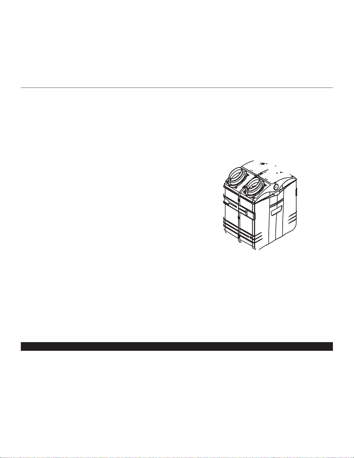
HRV 2600
INSTALLATION INSTRUCTIONS
AND USER MANUAL
RESIDENTIAL USE ONLY
INSTALLER: LEAVE THIS MANUAL WITH THE HOMEOWNER.
HOMEOWNER: USE AND CARE INFORMATION ON PAGES 18 TO 21.
READ AND SAVE THESE INSTRUCTIONS
04313 rev. G
MODELS
ABOUT THIS MANUAL
First, we want to congratulate you on your purchase of this excellent unit which will allow you and your family to enjoy clean and healthy
air throughout your home for years to come!
Because of the large amount of models covered by this publication, the illustrations are typical ones. Some details of your unit may be
slightly different than the ones shown.
Please take note that this manual uses the following symbols to emphasize particular information:
NOTE: Indicates supplementary information needed to fully complete an instruction.
We welcome any suggestions you may have concerning this manual and/or the unit, and we would appreciate hearing your comments
on ways to better serve you. Please contact us by phone at one of the following numbers:
Exclusively for HR and HF Models: Exclusively for HRV and HEPA Models:
Broan-NuTone Canada Inc. Venmar Ventilation inc.
1-866-737-7770 1-800-567-3855
WARNING
Identifies an instruction which, if not followed, might cause serious personal injuries including possibility of death.
!
CAUTION
Denotes an instruction which, if not followed, may severely damage the unit and/or its components.
- 2 -
!
TO REDUCE THE RISK OF FIRE, ELECTRIC SHOCK, OR INJURY TO PERSON(S) OBSERVE THE FOLLOWING:
1. This unit is intended for residential installation only.
2. Use this unit only in the manner intended by the manufacturer. If you have questions, contact the manufacturer at the address or
telephone number listed in the warranty.
3. Before replacing filters, servicing or cleaning unit, disconnect power cord from electrical outlet.
4. Installation must be done in accordance with all applicable codes and standards, including fire-rated construction codes and standards.
5. This unit is not designed to provide combustion and/or dilution air for fuel-burning appliances.
6. When cutting or drilling into wall or ceiling, do not damage electrical wiring and other hidden utilities.
7. Do not use this unit with any solid-state speed control device other than optional wall controls 40415 and 40425.
8. This unit must be grounded. The power supply cord has a 3-prong grounding plug for your personal safety. It must be plugged into a
mating 3-prong grounding receptacle, grounded in accordance with the national electrical code and local codes and ordinances. Do
not remove the ground prong. Do not use an extension cord.
9. Do not install in a cooking area or connect directly to any appliances.
10. Do not use to exhaust hazardous or explosive materials and vapors.
CAUTION
1. To avoid prematurate clogged filters, turn OFF the unit during constr uction or renovation.
2. Please read specification label on product for further information and requirements.
3. Be sure to duct air outside – Do not intake / exhaust air into spaces within walls or ceiling or into attics, crawl spaces, or garage.
4. Intended for residential installation only in accordance with the requirements of NFPA 90B.
5. Do not run any air ducts directly above or closer than 2 ft (0.61 m) to any furnace or its supply plenum, boiler, or other heat producing
appliance. If a duct has to be connected to the furnace retur n plenum, it must be connected not closer than 9’ 10” (3 m) from this
plenum connection to the furnace.
6. The ductwork is intended to be installed in compliance with all local and national codes that are applicable.
WARNING
ABOUT THESE UNITS

1. TYPICAL INSTALLATIONS . . . . . . . . . . . . . . . . . . . . . . . . . . . . . . . . . . . . . . . . . . . . . . . . . . . . . . . . . .4-6
1.1 HRV 2600, HR 2.6, HEPA 3100, HF 3.1 AND HEPA 4100 UNIT INSTALLATIONS . . . . . . . . . . . . . . . . . . . . . . . . . . 4
1.1.1 S
TA ND ALONE . . . . . . . . . . . . . . . . . . . . . . . . . . . . . . . . . . . . . . . . . . . . . . . . . . . . . . . . . . . . . . . . . . . . . . . .4
1.1.2 CENTRAL DRAW POINT . . . . . . . . . . . . . . . . . . . . . . . . . . . . . . . . . . . . . . . . . . . . . . . . . . . . . . . . . . . . . . . . .4
1.1.3 R
ETURN-TO-RETURN INSTALLATION . . . . . . . . . . . . . . . . . . . . . . . . . . . . . . . . . . . . . . . . . . . . . . . . . . . . . . . . .5
1.2 I
NSTALLATIONS FOR HEPA 4100 ONLY . . . . . . . . . . . . . . . . . . . . . . . . . . . . . . . . . . . . . . . . . . . . . . . . . . . . . . . . . . .5
1.2.1 GEOGRAPHICAL LOCATION . . . . . . . . . . . . . . . . . . . . . . . . . . . . . . . . . . . . . . . . . . . . . . . . . . . . . . . . . . . . . . .5
1.2.2 HEPA 4100 ATTIC INSTALLATION . . . . . . . . . . . . . . . . . . . . . . . . . . . . . . . . . . . . . . . . . . . . . . . . . . . . . . . . . .6
2. DIMENSIONS . . . . . . . . . . . . . . . . . . . . . . . . . . . . . . . . . . . . . . . . . . . . . . . . . . . . . . . . . . . . . . . . . . . .7
2.1 HRV 2600 AND HR 2.6 UNITS . . . . . . . . . . . . . . . . . . . . . . . . . . . . . . . . . . . . . . . . . . . . . . . . . . . . . . . . . . . . . . . .7
2.2 HEPA 3100, HF 3.1
AND HEPA 4100 UNITS . . . . . . . . . . . . . . . . . . . . . . . . . . . . . . . . . . . . . . . . . . . . . . . . . . . . . .7
2.3 MOUNTING AND SERVICING CONSIDERATIONS . . . . . . . . . . . . . . . . . . . . . . . . . . . . . . . . . . . . . . . . . . . . . . . . . . . . . .7
3. BEFORE STARTING . . . . . . . . . . . . . . . . . . . . . . . . . . . . . . . . . . . . . . . . . . . . . . . . . . . . . . . . . . . . . . . .8
3.1 INSPECT THE CONTENT OF THE BOX . . . . . . . . . . . . . . . . . . . . . . . . . . . . . . . . . . . . . . . . . . . . . . . . . . . . . . . . . . . . .8
3.2 TOOLS, MATERIALS AND INSTALLATION KITS . . . . . . . . . . . . . . . . . . . . . . . . . . . . . . . . . . . . . . . . . . . . . . . . . . . . . . .8
3.3 L
OCATING THE UNIT . . . . . . . . . . . . . . . . . . . . . . . . . . . . . . . . . . . . . . . . . . . . . . . . . . . . . . . . . . . . . . . . . . . . . . . .8
4WALL CONTROL INSTALLATION . . . . . . . . . . . . . . . . . . . . . . . . . . . . . . . . . . . . . . . . . . . . . . . . . . .9-10
5I
NSTALL THE UNIT . . . . . . . . . . . . . . . . . . . . . . . . . . . . . . . . . . . . . . . . . . . . . . . . . . . . . . . . . . . .11-17
5.1 MOUNT THE PORTS ON THE UNIT . . . . . . . . . . . . . . . . . . . . . . . . . . . . . . . . . . . . . . . . . . . . . . . . . . . . . . . . . . . . .11
5.2 H
OW TO HANG THE UNIT . . . . . . . . . . . . . . . . . . . . . . . . . . . . . . . . . . . . . . . . . . . . . . . . . . . . . . . . . . . . . . . . . . .11
5.3 PLANNING OF THE DUCTWORK . . . . . . . . . . . . . . . . . . . . . . . . . . . . . . . . . . . . . . . . . . . . . . . . . . . . . . . . . . . . . . .12
5.4 INSTALLING NON-INSULATED DUCTS AND REGISTERS . . . . . . . . . . . . . . . . . . . . . . . . . . . . . . . . . . . . . . . . . . . . .12-14
5.4.1 STA ND ALONE SYSTEM . . . . . . . . . . . . . . . . . . . . . . . . . . . . . . . . . . . . . . . . . . . . . . . . . . . . . . . . . . . . . .12-13
5.4.2 C
ENTRAL DRAW POINT . . . . . . . . . . . . . . . . . . . . . . . . . . . . . . . . . . . . . . . . . . . . . . . . . . . . . . . . . . . . .13-14
5.4.3 RETURN-TO-RETURN . . . . . . . . . . . . . . . . . . . . . . . . . . . . . . . . . . . . . . . . . . . . . . . . . . . . . . . . . . . . . . . . . .14
5.5 INSTALLING INSULATED FLEXIBLE DUCTS . . . . . . . . . . . . . . . . . . . . . . . . . . . . . . . . . . . . . . . . . . . . . . . . . . . . . . .15-16
5.5.1 C
ONNECTION TO TANDEM® TRANSITION . . . . . . . . . . . . . . . . . . . . . . . . . . . . . . . . . . . . . . . . . . . . . . . . . . .15
5.5.2 CONNECTION TO THE 5” TO 6” OVAL PORTS OF THE UNIT . . . . . . . . . . . . . . . . . . . . . . . . . . . . . . . . . . .15-16
5.6 INSTALLING DUAL EXTERIOR HOOD . . . . . . . . . . . . . . . . . . . . . . . . . . . . . . . . . . . . . . . . . . . . . . . . . . . . . . . . .16-17
5.6.1 A
SSEMBLING DUAL EXTERIOR HOOD . . . . . . . . . . . . . . . . . . . . . . . . . . . . . . . . . . . . . . . . . . . . . . . . . . . . . .16
5.6.2 LOCATING THE DUAL EXTERIOR HOOD . . . . . . . . . . . . . . . . . . . . . . . . . . . . . . . . . . . . . . . . . . . . . . . . . . . .16
5.6.3 C
ONNECTING TANDEM® TRANSITION TO THE DUAL EXTERIOR HOOD . . . . . . . . . . . . . . . . . . . . . . . . . . .16-17
5.7 CONNECTING THE DRAIN . . . . . . . . . . . . . . . . . . . . . . . . . . . . . . . . . . . . . . . . . . . . . . . . . . . . . . . . . . . . . . . . . . .17
6CONTROLS . . . . . . . . . . . . . . . . . . . . . . . . . . . . . . . . . . . . . . . . . . . . . . . . . . . . . . . . . . . . . . . . .18-19
6.1 MAIN SWITCH . . . . . . . . . . . . . . . . . . . . . . . . . . . . . . . . . . . . . . . . . . . . . . . . . . . . . . . . . . . . . . . . . . . . . . . . . . . .18
6.2 40415 AND 40425 WALL CONTROLS DESCRIPTION . . . . . . . . . . . . . . . . . . . . . . . . . . . . . . . . . . . . . . . . . . . . . . . . .18
6.3 OPERATING 40415 / 40425 CONTROLS . . . . . . . . . . . . . . . . . . . . . . . . . . . . . . . . . . . . . . . . . . . . . . . . . . . . . . . . .18
6.4 W
ALL CONTROLS CONFIGURATION . . . . . . . . . . . . . . . . . . . . . . . . . . . . . . . . . . . . . . . . . . . . . . . . . . . . . . . . . . . . .19
7MAINTENANCE . . . . . . . . . . . . . . . . . . . . . . . . . . . . . . . . . . . . . . . . . . . . . . . . . . . . . . . . . . . . . . .20-21
7.1 BIANNUAL MAINTENANCE . . . . . . . . . . . . . . . . . . . . . . . . . . . . . . . . . . . . . . . . . . . . . . . . . . . . . . . . . . . . . . . . .20-21
7.2 A
NNUAL MAINTENANCE . . . . . . . . . . . . . . . . . . . . . . . . . . . . . . . . . . . . . . . . . . . . . . . . . . . . . . . . . . . . . . . . . . . . .21
8PARTS ORDERING CHART . . . . . . . . . . . . . . . . . . . . . . . . . . . . . . . . . . . . . . . . . . . . . . . . . . . . . . . . .22
9T
ROUBLESHOOTING . . . . . . . . . . . . . . . . . . . . . . . . . . . . . . . . . . . . . . . . . . . . . . . . . . . . . . . . . . . . . .22
TABLE OF CONTENTS
- 3 -
1. TYPICAL INSTALLATIONS
Installations may vary according to the model number and the position in which the unit is installed. Use the following illustrations as
guidelines to help you decide on how your unit will be installed.
All the units should be hung from the joists, and installed either vertically or horizontally.
NOTE: For more details, see Point 5.2 in Section 5 INSTALL THE UNIT.
In every case, bathroom fans and a range hood should be used to exhaust stale air. Also, for homes with more than one level, we
recommend one exhaust register at the highest level.
There are 3 installation methods: Stand Alone, Central Draw Point and Return-to-Return Installation.
NOTE: An electrical outlet has to be available within 3 feet of the unit.
- 4 -
1.1 HRV 2600, HR 2.6, HEPA 3100, HF 3.1 AND HEPA 4100 UNIT INSTALLATIONS
1.1.1 STAND ALONE (PRIMARILY FOR HOMES WITH RADIANT HOT WATER OR ELECTRIC BASEBOARD HEATING.)
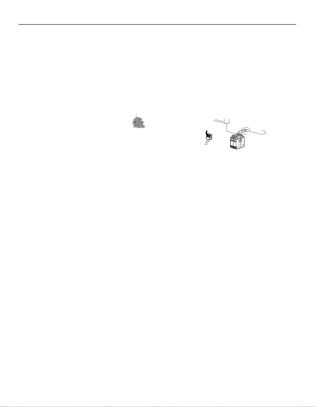
1. TYPICAL INSTALLATIONS (CONT’D)
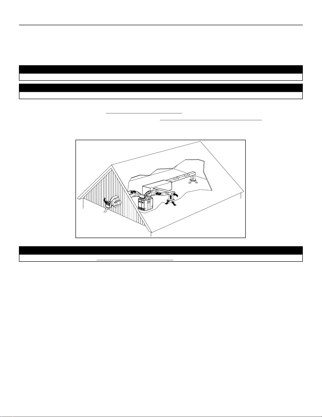
All 3 types of installations can be used in the attic (Stand Alone, Central Draw Point or Return-Return). The example shown below is a
Return-Return installation (connection to a forced air system).
VH0051
- 6 -
A portion of stale air is exhausted to the outside and the rest is drawn to the unit. Outside fresh air is blended with interior air and then
filtered. This filtered air is supplied to the return (plenum) of the forced air unit.
To avoid cross-contamination and achieve the highest efficiencies, the forced air system blower must always be ON. See figure below.
NOTE: Home with multiple forced air systems should have 1 unit on each system.
Do not connect the HEPA 4100 to any forced air system supply duct.
CAUTION
Due to the potential temperature difference between the attic and the rest of the house, all unit ducts must be insulated.
CAUTION
The attic temperature must always be above 0°C (32°F).
CAUTION
1. TYPICAL INSTALLATIONS (CONT’D)
1.2 INSTALLATION FOR HEPA 4100 ONLY (CONT’D)
1.2.2 HEPA 4100 ATTIC INSTALLATION
- 7 -
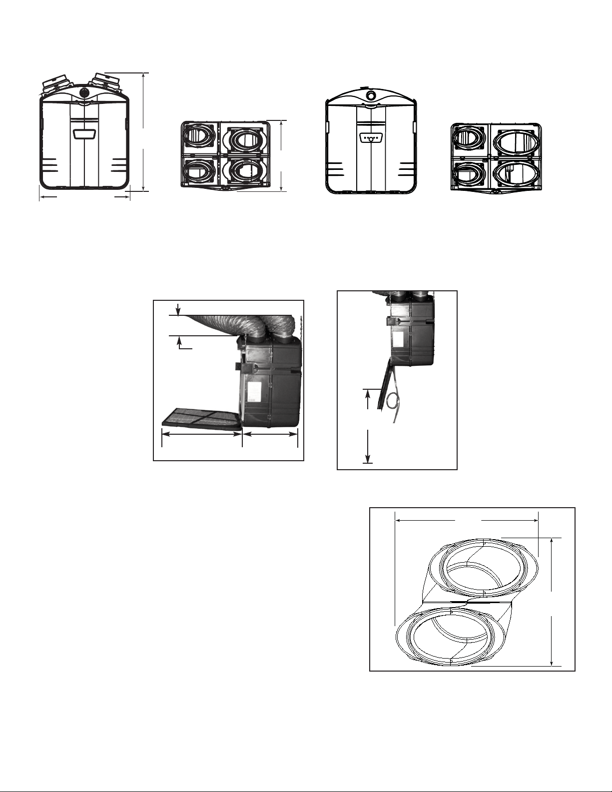
2.3 MOUNTING AND SERVICING CONSIDERATIONS
• The two following pictures are showing the minimum clearance needed to open the door completely.
22.5” 15.75”
(572 mm) (400 mm)
VD0117
VD0116
22”
(559 mm)
NOTE: A minimum of 8” (203 mm) clearance from any obstruction on top of the unit is required for the ductwork radius turn.
8”
(203 mm)
VD0118A
8 ¾”
222 mm
9 ¾”
248 mm
• The joist opening needed to install the Tandem
®
tansition (included in
both installation kits) must be 9 ¾” (248 mm) minimum. Also, the maximum
height of the Tandem transition is 8 ¾” (222 mm). See Tandem transition
end view beside.
2.2 HEPA 3100, HF 3.1 AND HEPA 4100 UNITS
FRONT VIEW TOP VIEW
2.1 HRV 2600
AND HR 2.6 UNITS
FRONT VIEW TOP VIEW
17.8''
(452 mm)
30.2''
(767 mm)
22.9'' (581 mm)
VK0049A
 Loading...