

Page 1
Installation and User Manual
PRO225 & PRO250
HEAT RECOVERY VENTILATORS
READ AND SAVE THESE INSTRUCTIONS
Venmar Ventilation inc., 550 Lemire Blvd., Drummondville, QC, Canada J2C 7W9
www.venmar.ca
VB0121
These products earned the
ENERGY STAR®by meeting strict
energy efficiency guidelines set by
Natural Resources Canada and the
US EPA. They meet ENERGY STAR
requirements only when used
in Canada.
08305 rev. C
Page 2

2
!
TO REDUCE THE RISK OF FIRE, ELECTRIC SHOCK, OR INJURY TO PERSON(S)
OBSERVE THE FOLLOWING:
1. These units are intented for residential installation only.
2. Use these units only in the manner intended by the manufacturer. If you have questions,
contact the manufacturer at the address or telephone number listed in the warranty.
3. Before servicing or cleaning the units, disconnect power cord from electrical outlet.
4. Installation must be done in accordance with all applicable codes and standards, including
fire-rated construction codes and standards.
5. These units are not designed to provide combustion and/or dilution air for fuel-burning
appliances.
6. When cutting or drilling into wall or ceiling, do not damage electrical wiring and other
hidden utilities.
7. Do not use these units with any solid-state speed control devices other than the Breeze
main control for the PRO250 unit exclusively or the 11136 main control for PRO225 unit.
The optional auxiliary control 20-minute lighted push button can be used with both
PRO250 and PRO225 units.
8. These units must be grounded. The power supply cord has a 3-prong grounding plug for
your personal safety. It must be plugged into a mating 3-prong grounding receptacle,
grounded in accordance with the national electr ical code and local codes and
ordinances. Do not remove the ground prong. Do not use an extension cord.
9. Do not install in a cooking area or connect directly to any appliances.
10. Do not use to exhaust hazardous or explosive materials and vapors.
11. Do not run any air ducts directly above or closer than 2 ft (0.61 m) to any furnace or
its supply plenum, boiler, or other heat producing appliance.
12. When performing installation, servicing or cleaning of these units, it is recommended to
wear safety glasses and gloves.
13. When applicable local regulations comprises more restrictive installation and/or
certification requirements, the aforementioned requirements prevail on those of this
document and the installer agrees to conform to these at his own expenses.
CAUTION
1. To avoid premature clogged filters, turn OFF the unit during construction or renovation.
2. Please read specification label on product for further information and requirements.
3. Be sure to duct air outside – Do not intake or exhaust air into spaces within walls or
ceiling or into attics, crawl spaces, or garage.
4. Intended for residential installation only in accordance with the requirements of NFPA 90B.
5. The ductwork is intended to be installed in compliance with all applicable codes.
6. Do not use the PRO250 or PRO225 unit when varnishing. The varnish vapors may
damage these units.
7. At least once in a year, the unit mechanical and electronic parts should be inspected
by qualified service personnel.
8. During snow/rain storm, operate the PRO250 unit in recirculation mode to prevent water
build up in the heat recovery ventilator. Tur n OFF the PRO225 unit.
WARNING
Page 3

1. FUNCTIONS OF YOUR HEAT RECOVERY VENTILATOR..........................4
1.1 Air Exchange...............................................................................................4
1.2 Heat Recovery ............................................................................................4
1.3 Recirculation (PRO250 only).......................................................................4
2. DIAGRAMS OF AIRFLOWS...............................................................5
3. DESCRIPTION OF THE UNIT .............................................................6
4. UNITS INSTALLATION ................................................................7-13
4.1 Installation Types with Required Installation Kit..........................................7
4.2 Locating and Mounting the Unit ..................................................................8
4.3 Tools and Materials .....................................................................................8
4.4How to Hang the Unit..................................................................................8
4.5 Planning of the Ductwork ............................................................................9
4.6Installing Non-Insulated Flexible Ducts and Registers ..........................9-10
4.7 Connecting Insulated Flexible Ducts to the Unit Ports..............................11
4.8 Locating Exterior Ports..............................................................................12
4.9 Connecting Insulated Ducts to EXterior Ports ...........................................12
4.10 Connecting the Drain ................................................................................13
5. CONTROLS ............................................................................13-16
5.1 Integrated Control .....................................................................................13
5.2 Controls Connection to the Unit...........................................................14-15
5.3 Main Control Installation............................................................................16
6. OPERATING CONTROLS ..........................................................17-18
6.1 Breeze Main Control (PRO250 only) ........................................................17
6.2 11136 Main Control (PRO225 only)..........................................................18
6.3 20-minute Lighted Push Button Optional Auxiliary Control
(PRO250 & PRO225)..........................................................................................18
7. MAINTENANCE ............................................................................19
7.1 Regular Maintenance ................................................................................19
7.2 Annual Maintenance .................................................................................19
8. TROUBLESHOOTING .....................................................................20
TABLE OF CONTENTS
Congratulations!
You have made an excellent choice!
The operating principle of your Heat Recovery Ventilator will protect your house and give
you personal comfort you have never known before.
We have prepared this Manual especially for you. Please read it carefully to ensure you
obtain full benefit from your Heat Recovery Ventilator unit.
Please take note this manual uses the follo wing symbols to emphasize particular information:
NOTE: Indicates supplementary information needed to fully complete an instruction.
We welcome any suggestions you may have concerning this manual and/or the unit, and we
would appreciate hearing your comments on ways to better serve you. Please forward all
correspondence to us at the address indicated on the product registration card included with
this manual.
WARNING
Identifies an instruction which, if not followed, might cause serious
personal injuries including possibility of death.
!
CAUTION
Denotes an instruction which, if not followed, may severely damage the
unit and/or its components.
3
Page 4

1.1 AIR EXCHANGE (PRO250 & PRO225)
4
1. FUNCTIONS OF YOUR HEAT RECOVERY VENTILATOR
Your PRO250 or PRO225 Heat Recovery Ventilator eliminates the excessive humidity
problems by exhausting stale and humid air to the outside and by drawing in fresh air. Either
unit offers superior air quality and fresh air sensation, an important factor to overall comfort,
by eliminating the accumulation of
pollutants and humidity.
These units also come equipped with a heat recovery core which reduces ventilating costs
in winter.
The PRO250 and PRO225 Heat Recovery Ventilators are ventilation systems which carry
out the following operations:
During winter, these units recover the heat contained in the stale air before it is exhausted,
and transfer it to the fresh air drawn from the outside (reverse process in summer).
These units exhaust stale and humid air from the house and replace it with fresh air from
the outside.
1.2 HEAT RECOVERY (PRO250 & PRO225)
Example (in winter):
VF0015
STALE AIR TO OUTSIDE
4°C/39°F
FRESH AIR FROM OUTSIDE
0°C/32°F
FRESH AIR TO BUILDING
18°C/64°F
STALE AIR FROM BUILDING
22°C/72°F
1.3 RECIRCULATION (PRO250 ONLY)
During the recirculation mode, this unit stops to exchange air with the exterior. Continuous
recirculation is thus undertaken inside the home and insures the purification of the ambient
air. Tw o mechanical filters trap the large dust particles (those visible to the eye).
Page 5
5
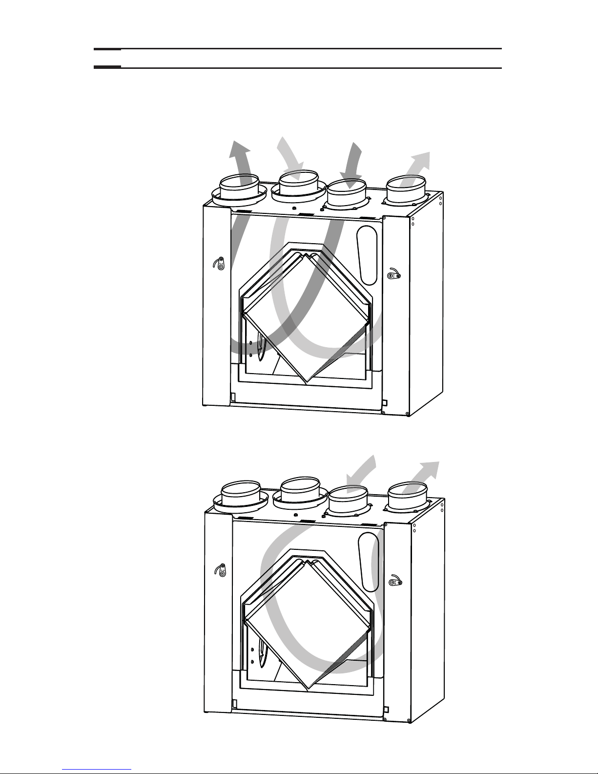
2. DIAGRAMS OF AIRFLOWS
The direction of the airflows is indicated in each of the following diagrams. Please note that
the stale air never mixes with the fresh air.
DURING
AIR EXCHANGE
VF0045
FRESH AIR
FROM OUTSIDE
FRESH AIR
TO BUILDING
STALE AIR
FROM BUILDING
STALE AIR
TO OUTSIDE
DURING
DEFROST MODE
OR
RECIRCULATION
(PRO250 ONLY)
VF0046
FILTERED AIR
TO BUILDING
STALE AIR
FROM BUILDING
Page 6
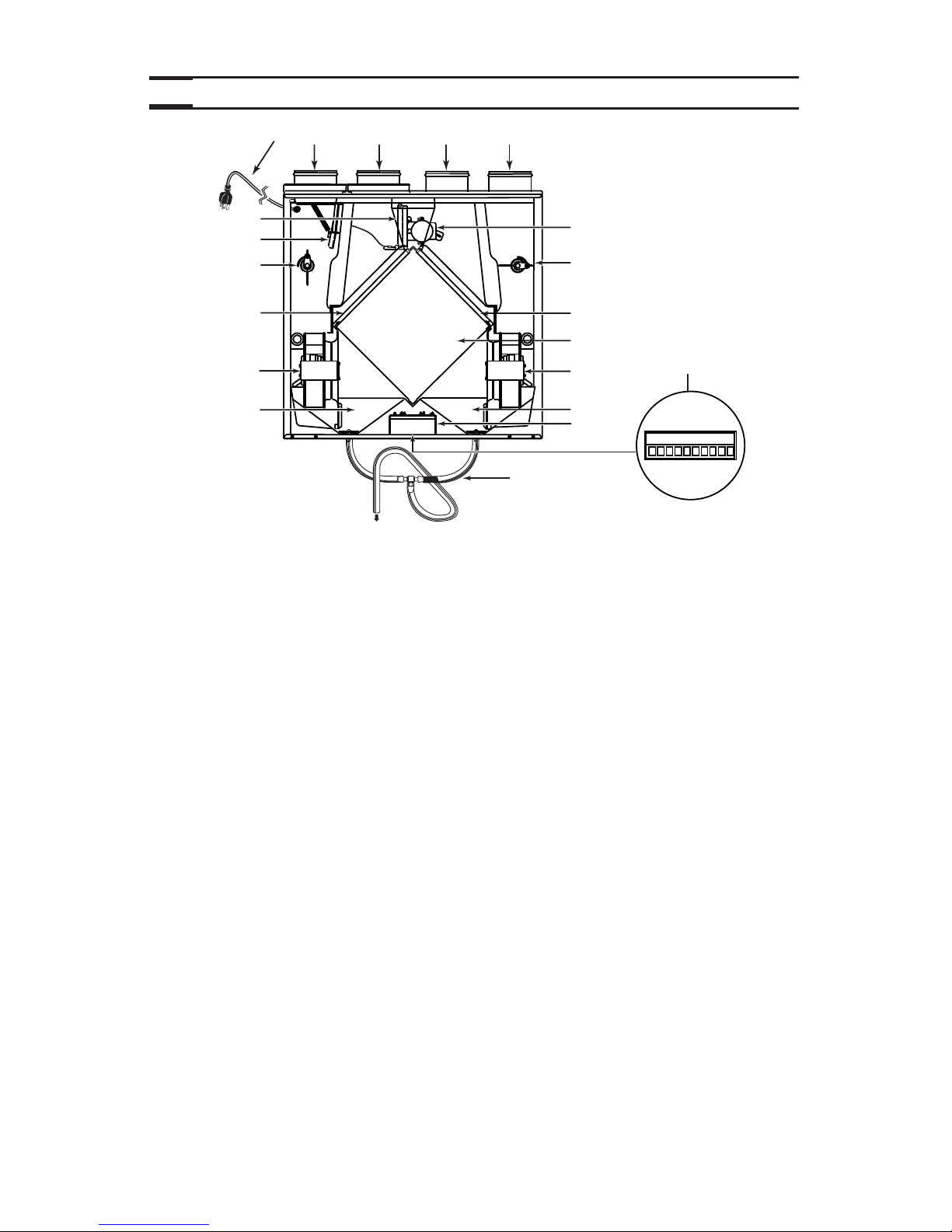
3. DESCRIPTION OF THE UNIT
6
VL0035
16
14
8
11
9
3 214
10
9
11
8
13
12
6
5
7
12
15
1 Exhaust port: exhausts stale air to the outside, after the air has transferred its
heat inside the heat recovery core.
2 Fresh air port: brings fresh air from the outside into the unit.
3 Stale air intake port: is connected to the registers located in the larger rooms of the
house.
4 Distribution port: distributes fresh air into the house, after it has absorbed the
heat of the stale air in the heat recovery core.
5 Main damper: allows fresh air intake when open and defrost when closed.
6 Secondary damper: allows stale air to exhaust when open and prevents negative
pressure when closed, in defrost mode.
7 Automatic defrost
unit :
consists of one damper actuator, dampers and related controls.
The defrost cycle is electronically controlled in response to the
outside temperature (-5°C [23°F] to -27°C [-17°F] or coldest)
and will increase in frequency as the temperature decreases.
Its duration is of 7 or 10 minutes.
8 Adjusting tools (2): adjust the dampers (one on each side) in balancing process.
Lock them in place once the unit is balanced.
9 Mechanical filters (2): trap the dust contained in the air and prevents the heat
recovery core from becoming obstructed.
10 Heat recovery core: is a crossflow type. It transfers the heat between the two air
streams.
11 Blowers (2): draw fresh air from the outside and exhaust stale air to the outside.
12 Condensation tray: is used to capture the water produced during heat transfer and
defrost (in cold climate).
13 Electrical cord: for 120 V electrical supply.
14 Electrical box: contains capacitors (indispensable to proper motors operation)
and electronic control circuit (insures proper operation of the
unit).
15 Terminal connector: located under the unit, allows to connect the controls.
16 Drainage tube: is connected to the condensation tray and serves to drain the
water accumulation.
Page 7
7
4. UNIT INSTALLATION
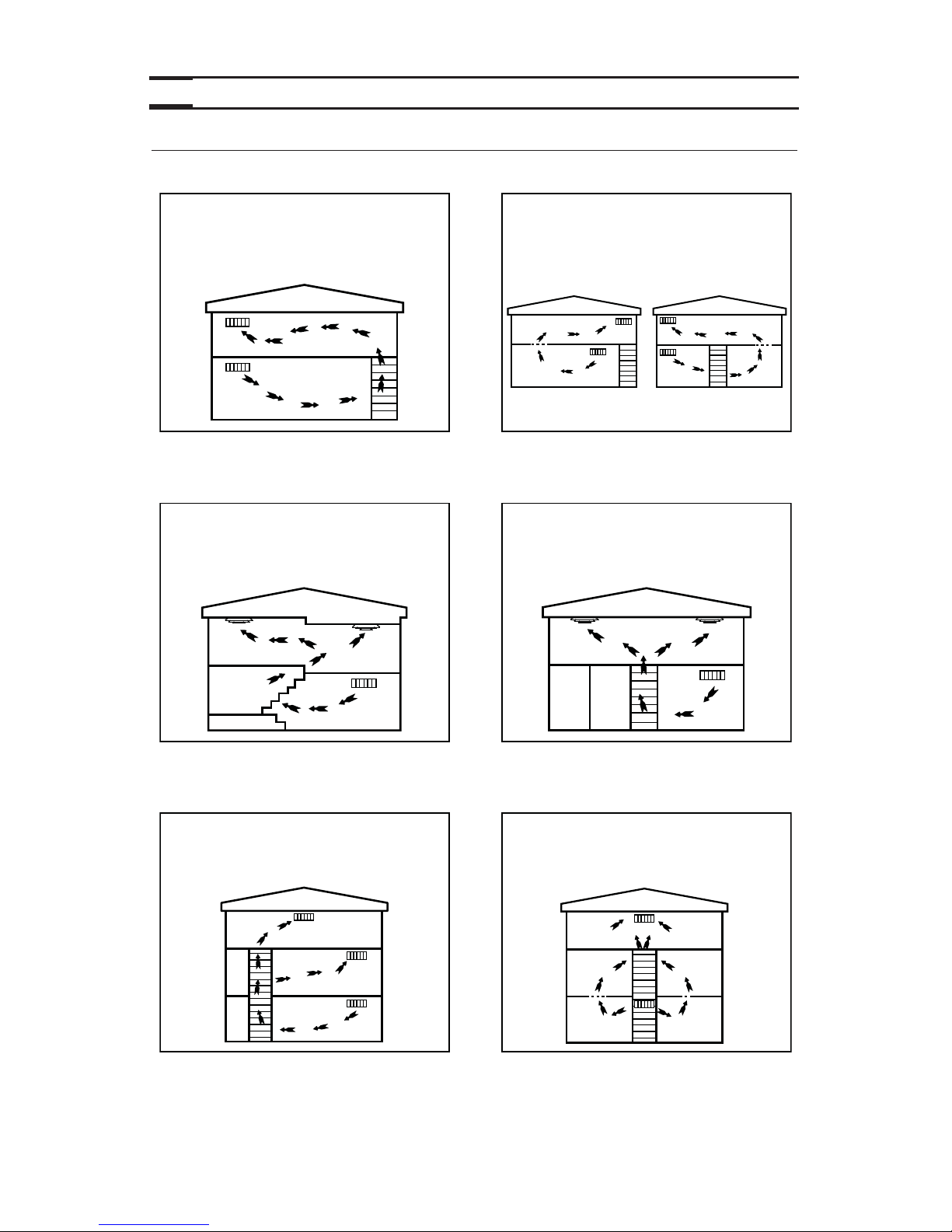
4.1 INSTALLATION TYPES WITH REQUIRED INSTALLATION KIT
Here are the types of installation and installation kit needed depending on your house.
BUNGALOW
• LATERAL STAIRWAY
• OPEN BASEMENT STAIRWELL
BUNGALOW
• CENTRAL STAIRWAY
• OPEN BASEMENT STAIRWELL
2-STORIED HOUSE
• OPEN BASEMENT STAIRWELL
MULTI-LEVEL HOUSE
• 4 LEVELS
BUNGALOW
• LATERAL OR CENTRAL STAIRWAY
• CLOSED-IN BASEMENT STAIRWELL
2-STORIED HOUSE
• CENTRAL STAIRWAY
• CLOSED-IN BASEMENT STAIRWELL
Basement installation kit no. CH30115.
Basement installation kit no. CH30115
with one additional register (not included).
Basement installation kit no. CH30115
with additional multi-level kit
no. UT 2004.
Basement installation kit no. CH30115
with 3 or 4 floor registers (4” x 10”, not
included).
Basement installation kit no. CH30115
with 3
or 4 floor registers (4” x 10”, not
included).
Basement installation kit no CH30115
with additional multi-level kit
no. UT 2004.
Page 8
4. UNIT INSTALLATION (CONT’D)
4.2 LOCATING AND MOUNTING THE UNIT
Choose an appropriate location for the unit:
• Within a heated area of the house (10 °C/50 °F or more)
• Away from living areas (dining room, living room, bedrooms), if possible
• So as to provide easy access for filter maintenance
• Close to an exterior wall, so as to limit the length of the insulated flexible ducts to
and from the unit
• Close to a drain. (If no drain is close by, use a pail to collect run-off)
• Away from hot chimneys, electrical panel and other fire hazards
• Allow for a power source (standard 3-prong grounding outlet)
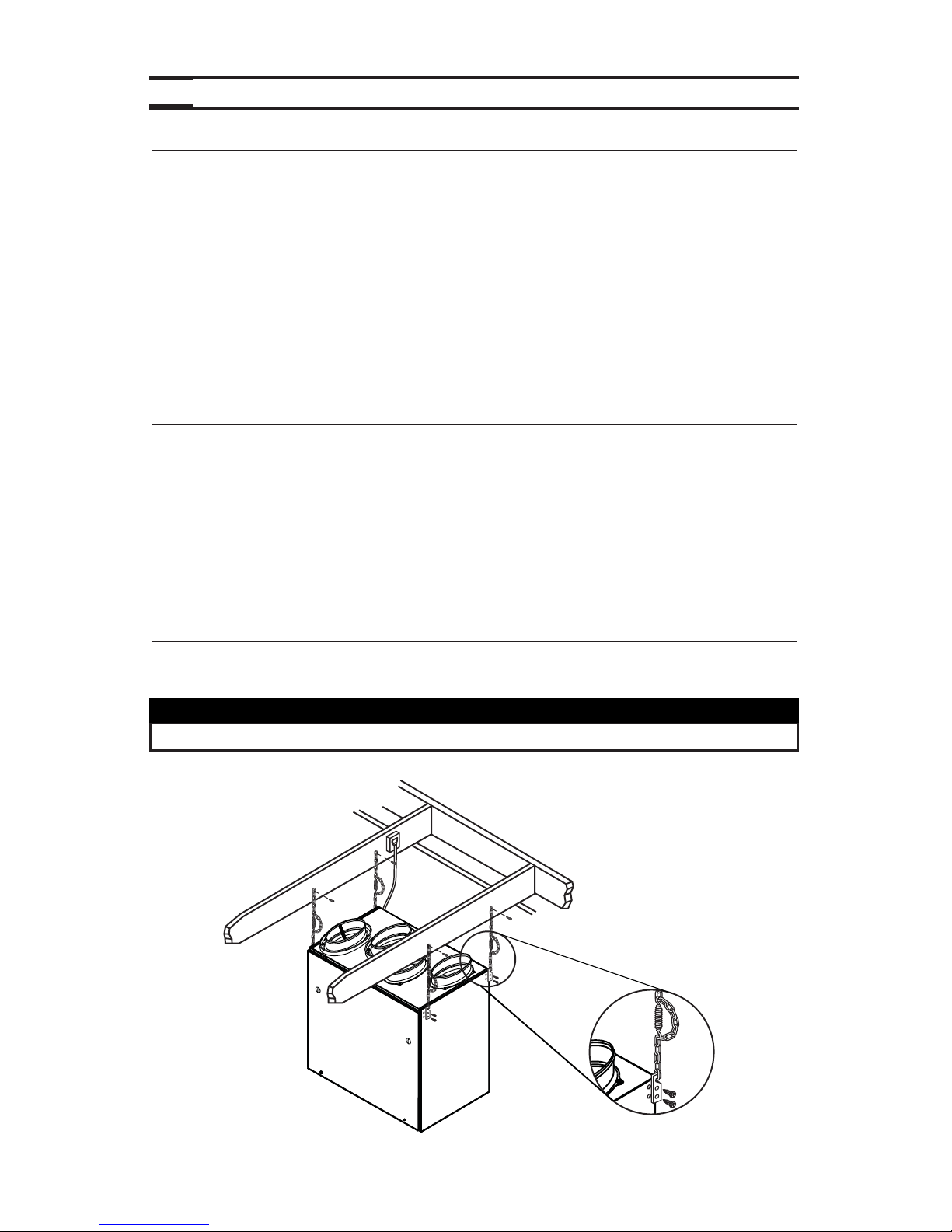
Use the 4 chains and springs (from the hardware pack included with the unit) to hang the
unit to ceiling joists.
• Robertson no. 2 or
Phillips no. 2 screwdriver
• Cutter pliers
• Drill
• Jig saw
• Duct tape
• Caulking gun with a tube of silicone
sealant
•Metal shears (if the exterior covering is
aluminum or vinyl)
• Chisel and hammer (if the exterior covering
is brick)
4.3 TOOLS AND MATERIALS
4.4 HOW TO HANG THE UNIT
CAUTION
Make sure the unit is level.
VD0204
8
Page 9

4. UNIT INSTALLATION (CONT’D)
4.5 PLANNING OF THE DUCTWORK
•Keep it simple. Plan for a minimum of bends and joints. Keep the length of the
insulated ducts to a minimum.
• Do not use wall cavities as ducts. Do not use branch line smaller than 4” (102 mm)
diameter.
• Do not ventilate crawl spaces or cold room. Do not attempt to recover the exhaust
air from a dryer or a range hood; this will cause the clogging of the unit.
• Be sure to plan at least one exhaust register on the highest lived-in level of the
house, if it has 2 floors or more.
4.6 INSTALLING NON-INSULATED FLEXIBLE DUCTS AND REGISTERS
4.6.1 STALE AIR EXHAUST DUCTWORK
4.6.2 FRESH AIR DISTRIBUTION DUCTWORK
CAUTION
If ducts have to go through an unconditioned space, always use insulated
ducts (purchase separately).
WARNING
Never install a stale air exhaust register in a room where a combustion
device operates, such as a gas water heater, a gas furnace or a fireplace.
!
•Install the stale air exhaust register(s) in the main area where the contaminants
are produced: kitchen, living room, etc. Position the register(s) as far from the
stairway as possible and in such a way that the air circulates in all the lived-in
spaces in the house.
•If a register is installed in the kitchen, it must be located at least 4 feet (1.2 m)
from the range.
•Install the register(s) 6 to 12 inches (152 to 305 mm) from the ceiling on an
interior wall OR install it in the ceiling.
•Install the fresh air distribution register(s) in
a large, open area in the lowest
level to ensure the greatest possible air circulation. Keep in mind that the fresh
air register(s) must be located as far as possible from the stale air register(s).
•Install the register(s) in the ceiling OR 6 to 12 inches (152 to 305 mm) from the
ceiling on an interior wall. The duct length should be at least 15 feet (4.6 m).
(The cooler air will then cross the upper part of the room and mix with room air
before descending to occupant level.)
4.6.3 HOW TO CONNECT NON-INSULATED FLEXIBLE DUCTS TO THE REGISTERS
•Once the register location is determined,
cut out a 3¾” x 9¾” rectangular hole.
•Fix one end of the flexible duct to the register
transition (1), using a tie wrap and duct tape.
•From inside the wall (or ceiling), place the
transition opening flush to the finished w all.
• Assemble the register (2) to its transition
using its 2 no. 8 x 1½” screws.
See illustration beside.
VD0202
1
2
9
Page 10

A. FRESH AIR TO BUILDING DUCT ONLY
• Cut an opening into the return duct not less
than 10 feet (3.1 m) from the furnace (A+B).
• Use a metal transition (not provided,
available in hardware stores) to connect the
fresh air to building duct to the furnace
return duct.
NOTE:For this type of installation, it is not
essential that the furnace blower runs
when the unit is in operation, but we
recommend it.
4.6 INSTALLING NON-INSULATED FLEXIBLE DUCTS AND REGISTERS (CONT’D)
VJ0065
B
A
4.6.4 CONNECTION TO A FORCED AIR SYSTEM
10
4. UNIT INSTALLATION (CONT’D)
WARNING
When performing duct connections, always use approved tools and
materials. Respect all corresponding laws and safety regulations. Please
refer to your local building code.
!
METAL
TRANSITION
B. FRESH AIR TO BUILDING DUCT AND EXHAUST AIR FROM BUILDING DUCTS
Fresh air to building duct
• See point A above “Fresh air to building duct only”.
Exhaust air from building duct
• Cut an opening into
the retur n duct at
least at 3 feet (0.9 m)
from the fresh air
to building duct
connection to the
return plenum.
• Use a metal transition
(not provided, a vailab le
in hardware stores)
to connect the stale
air intake duct to the furnace return duct.
B
A
VJ0068
WARNING
When performing duct connections, always use approved tools and
materials. Respect all corresponding laws and safety regulations. Please
refer to your local building code.
!
CAUTION
For this type of installation, the furnace blower must be in operation when
the HRV is in operation.
A+B = NOT LESS
THAN 10’ (3.1 M)
A+B =
NOT LESS
THAN
10’ (3.1 M)
MINIMUM 3’
(0.9 M)
M
ETAL
TRANSITION
Page 11

4. UNIT INSTALLATION (CONT’D)
11
4.7 CONNECTING INSULATED FLEXIBLE DUCTS TO THE UNIT PORTS
CAUTION
Make sure the vapor barrier on the insulated ducts does not tear during
installation to avoid condensation within the ducts.
VJ0060
Fresh air from outside
Aspiration d’air frais
Exhaust air to outside
Évacuation d’air vicié
a) b)
c) d)
VO0148
Exhaust air from building
Aspiration d’air vicié
• Each port is identified on top of the unit (see illustrations below). Attach the
fresh air to building duct and the exhaust air from building duct to their
corresponding port, using tie wraps (1).
4.6.5 HOW TO CONNECT NON-INSULATED FLEXIBLE DUCTS TO THE UNIT PORTS
VO0147
Fresh air to building
Distribution d’air frais
1
Use the following procedure for connecting the insulated flexible ducts to the unit ports
(exhaust to outside and fresh air from outside).
a) Pull back the insulation to expose the flexible duct.
b) Connect the interior flexible duct to the port using a tie wrap.
c) Pull the insulation over the joint and tuck it between the inner and outer ring
of the double collar.
d) Pull down the vapor barrier (shaded part in illustrations below) over the
outer ring to cover it completely. Fasten in place the vapor barrier using the
port strap (included in unit parts bag). To do so, insert one collar pin
through vapor barrier and first strap hole, then insert the other collar pin
through vapor barrier and center strap hole and close the loop by inserting
the first collar pin in the last strap hole.
COLLAR PIN
COLLAR PIN
Page 12
4. UNIT INSTALLATION (CONT’D)
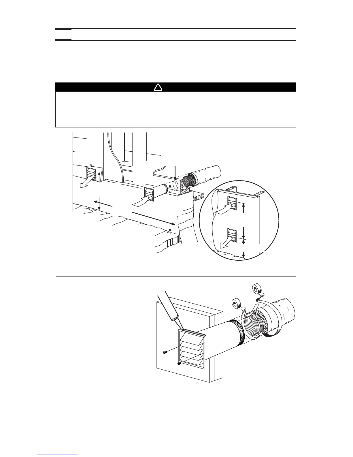
4.8 LOCATING EXTERIOR PORTS
Choose an appropriate location for installing the exterior ports:
• At a distance of at least 6 feet (1.8 m) one from the other
• At a minimum distance of 18 inches (457 mm) from the ground
12
WARNING
Make sure the fresh air intake port is at least 6 feet (1.8 m) away (or more, as per
applicable building codes or standards) from sources of contamination such as:
• High efficiency furnace vent • Any exhaust from a combustion source
• Gas meter exhaust, gas barbecue-grill • Garbage bin
!
VD0203
STALE
AIR
EXHAUST
PORT
FRESH
AIR
INTAKE
PORT
6’
(1.8 M)
6’
(1.8 M)
18’’
(457 MM)
18’’
(457 MM)
6” Ø
(152 MM)
18’’ (457 MM)
OPTIONAL
LOCATION
4.9 CONNECTING INSULATED DUCTS TO EXTERIOR PORTS
•For each exterior por t,
using a jig saw, cut a 6’’
diameter hole in the
exterior wall.
•From the outside, slide the
exterior port in place and
attach it to the exterior
wall, using 2 no. 8 x 1½”
provided screws. Seal the
outline with silicone.
•From the inside, pull back
the insulation to expose
the flexible duct and, using
a tie wrap, attach it to the
exterior por t rigid duct.
Carefully seal with duct
tape. Pull the insulation over the joint. Pull the vapor barrier over the insulation and
over the joint. Apply gently duct tape to the joint making an airtight seal. See above.
VR0028
Page 13

4. UNIT INSTALLATION (CONT’D)
13
5.1 INTEGRATED CONTROL
Those units are equipped with an integrated control, located under the unit, on the recessed
side of electrical compartment. Plug the unit. Use the push button (1) to control the unit. The
LED (2) will then show on which mode the unit is in.
VD0207
1
2
Refer to table below to see how to operate the unit using its integrated control.
PRESS ON PUSH BUTTON LED COLOR RESULTS
ONCE AMBER UNIT IS ON LOW SPEED
TWICE GREEN UNIT IS ON HIGH SPEED
THREE TIMES NO LIGHT UNIT IS OFF
4.10 CONNECTING THE DRAIN
Make a water trap loop in the tube to prevent the
unit from drawing unpleasant odors from the drain
source. Make sure this loop is located OVER the
“T” as shown. Run the tube to the floor drain or to
an alternative drain pipe or pail.
IMPORTANT
If using a pail to collect water, locate the tube end
approximately 1” from top of th epail in order to
prevent watter from being drawn back up into the
unit.
Cut 2 sections of the plastic tube, at least
16” (406 mm) long, and attach them to each inner
drain fitting, located under the unit. Join both
short sections to the “T” junction and main tube
as shown.
VO0154A
16"
(406 mm)
16"
(406 mm)
VD0232A
± 1”
TIE WRAP
5. CONTROLS
SEE PAGES 17 & 18
FORUNIT OPERATION.
BOTTOM OF THE UNIT
Page 14

5. CONTROLS (CONT’D)
14
5.2 CONTROLS CONNECTION TO THE UNIT
Use the terminal connector included in the
installation kit to perform the electr ical
connection for control. Check if all wires are
correctly inserted in their corresponding holes
in the terminal block. (A wire is correctly
inserted when its orange receptacle is lower
than another one without wire. On picture
beside, wire A is correctly inserted, but not
wire B.)
5.2.1 BREEZE MAIN CONTROL (PRO250 ONLY)
NO C NC I OC OL Y R G B
VE0180
C
O
M
F
O
R
T
Z
O
N
E
V
I
T
E
S
S
E
M
A
X
.
P
E
E
D
4
0
2
6
0
V
-
1
0
3
/
2
0
0
7
MIN.
AUTO
ÉCHANGE
AIR
EXCHANGE
RE-CIRC
EXCÈS D’HUMIDITÉ
EXCESS HUMIDITY
É
T
É
/
S
U
M
M
E
R
WARNING
Always disconnect the unit before making any connections. Failure in
disconnecting power could result in electrical shock or damage of the
control or electronic module inside the unit.
!
BOOT SEQUENCE
The unit boot sequence is similar to a personal computer boot sequence. Each times the unit
is plugged after being unplugged, or after a power failure, the unit will perform a30-second
booting sequence before star ting to operate. During the booting sequence, the integrated
control LED will light GREEN or AMBER for 5 seconds, and then will shut off for 2 seconds.
After that, the LED will light RED for the rest of the booting sequence. During this RED light
phase, the unit is checking and resetting the motorized damper position. Once the motorized
damper position completely set, the RED light turns off and the booting sequence is done.
NOTE: No command will be taken until the unit is fully booted.
5.1 INTEGRATED CONTROL (CONT’D)
If a problem occurs during the unit operation, its integrated control LED (2) will blink. The
color of the blinking light depends on the type of error detected. Refer to Section 8
Troubleshooting
on page 20 for further details.
A B
Page 15

5. CONTROLS (CONT’D)
15
Once the control(s) connection has been made, insert the terminal connector under the unit,
on the recessed side of the electrical compartment.
VD0207
TERMINAL
CONNECTOR
5.2.3 20-MINUTE LIGHTED PUSH BUTTON OPTIONAL AUXILIARY CONTROL
(PRO250 & PRO 225)
NO C NC I OC OL Y R G B
VE0185
ON
5.2 CONTROLS CONNECTION TO THE UNIT (CONT’D)
5.2.2 11136 MAIN CONTROL (PRO225 ONLY)
NO C NC I OC OL Y R G B
VE0190
% RELATIVE HUMIDITY
% HUMIDITÉ RELATIVE
0FF
55% 10°
45% 0°
35% -10 °
30% -20 °
%HUM. RELATIVE HUM EXT. TEMPS.°C EXT.
20
30
40
50
60
70
80
25
-30˚C
-20˚C
5˚C+
-5˚C
Page 16

5. CONTROLS (CONT’D)
16
1. Route the cable from the unit to a convenient location for the control.
2. Remove the button and the cover plate of the control (see figure
beside). If necessary, bore the mounting holes and insert anchors.
3. Pass the cable (4 wires) through the opening of the mounting plate and mount the plate
to the wall using the provided screws.
4. Splice back the end of the cable to access to the 4 wires.
Strip the end of each wire. Connect each wire to its
corresponding terminal: YELLOW wire to “Y’’, RED wire
to “R’’, GREEN to “G’’ and BLACK to “B’’. See illustration
beside.
5. Reinstall cover plate and button.
6. Plug the unit.
VC0110
YRGB
VE0124
5.3 MAIN CONTROLS INSTALLATION
For more convenience, the PRO250 and PRO225 units can also be controlled using the
included main controls: the Breeze main control for the PRO250 unit and the 11136 main
control for the PRO225 unit.
WARNING
Always disconnect the unit before making any connections. Failure in
disconnecting power could result in electrical shock or damage of the
control or electronic module inside the unit.
!
CAUTION
Failure to comply with the following can cause erratic operation of the unit:
• Never install more than one control per unit.
• Keep control low voltage wiring at least 1 foot (305 mm) away from
motors, lightning ballast, light dimming circuit and power distribution
panel. Do not route control wiring alongside electrical wires.
• Ensure the wires are securely connected.
• Disconnect power from the unit before removing the control faceplate
from its mounting plate.
The Breeze main control must be installed with the PRO250 unit only and
the 11136 main control with PRO225 unit.
CAUTION
Page 17

17
6. OPERATING CONTROLS
VC0109
C
O
M
F
O
R
T
Z
O
N
E
V
I
T
E
S
S
E
M
A
X
.
S
P
E
E
D
4
0
2
6
0
V
-
1
0
3
/
2
0
0
7
MIN.
AUTO
ÉCHANGE
AIR
EXCHANGE
RE-CIRC
EXCÈS D’HUMIDITÉ
EXCESS HUMIDITY
É
T
É
/
S
U
M
M
E
R
AUTOMATIC
MODE INDICATOR
MINIMUM SPEED
INDICATOR
RECIRCULATION
INDICATOR
PUSH BUTTON
NOTE: The integrated control must be turned OFF to use this control.
ADJUSTING AIR SUPPLY CONTROL
1) Select “RE-CIRC”, “MIN.” or “AUTO” using the push button.
• When “RE-CIRC” is selected, the recirculation indicator lights up. If the humidity control
knob is set to the left of the “click”, the unit will recirculate air on high speed and if it is
set to the right of the “click”, the unit will exchange air, on high speed, with the outside
until the desired humidity level has been reached. During this time, the excess humidity
and air exchange indicators will be lit.
• When “MIN.” is selected, the minimum speed and air exchange indicators light-up. If the
humidity control knob is set to the left of the “click”, the unit will exchange in low speed
with the outside and if it is set to the r ight of the “click”, the unit will exchange air, on
high speed, with the outside until the desired humidity level has been reached. During
this time, the excess humidity indicator will be lit.
• When “AUTO” is selected, the automatic indicator lights-up. If the humidity control knob
is set to the left of the “click”, the unit will turn OFF for the first 40 minutes and operate
on air exchange mode with the outside, in low speed, during the last 20 minutes of the
hour. The air exchange indicator will be lit. If the humidity control knob is set to the right
of the “click”, the unit will exchange air, on high speed, with the outside until the desired
humidity level has been reached. During this time, the excess humidity indicator will be lit.
2) To turn off the unit, press on the push button once again.
ADJUSTING HUMIDITY CONTROL
SETTING DURING THE SUMMER MONTHS:
During this period, unless being afflicted with breathing problems, using the humidity control
is unnecessary; set the unit in recirculation mode. (Do not exchange in day time; exchange
at night time if cool outside or if it’s not raining.)
SETTING DURING THE FALL, WINTER AND SPRING MONTHS (CONDENSATION APPEARS ON WINDOWS):
1) Determine the humidity level in your house (bring the knob counterclockwise to its
maximum position, then bring it back clockwise slowly until you hear a “click”).
2) Set the knob to one line under this temperature level or “click”.
6.1 BREEZE MAIN CONTROL (PRO250 ONLY)
CAUTION
Do not set a temperature below -20°C (-4°F). This could lead to excessive
dryness in the air causing discomfort for the occupants.
It is possible (and normal) to experience condensation on your windows when drastic
changes in temperature happen (for example: -5°C [23°F] to -20°C [-4°F]). In that case,
we suggest waiting a few days to allow the situation to stabilize.
HUMIDITY
CONTROL KNOB
EXCESS HUMIDITY
INDICATOR
AIR EXCHANGE
INDICATOR
Page 18

NOTE: The integrated control can be turned OFF (no light) or at Minimum speed (amber led)
to use this control.
USING THE HUMIDITY LEVEL SELECTOR:
Winter: (outside temperature between 5°C and -30°C)
– Position the selector between 50% and 25%,
pointing approximately to the corresponding
outside temperature.
–If there is condensation or frost on the windows,
then lower the humidity level by 1% to 2% every
24 hours until the condensation has evaporated.
– Do not go lower than 25%: the air will become too
dry for human comfort.
Spring and Fall:
– Position the selector anywhere between 75% and
50% (higher on warm days, lower on cold days).
–If certain periods during the spring and fall seem
more like winter, follow the instructions given for humidity control during the winter.
Summer:
– Position the selector at 80% during the day.
– Lower the selector to 20% to introduce cool fresh air into the house during certain
summer nights.
IMPORTANT EXPLANATIONS ABOUT HUMIDITY LEVELS:
The comfort level for human beings is between 30% and 45% relative humidity. To measure
the present humidity level in your house, proceed as follows:
– Tur n the dial to 80%.
– Tur n the dial slowly clockwise until you hear a “click”. The dial will then be pointing to
the value for the present humidity level (precision of 5%).
Tur n the selector to the right of the “click” to lower the humidity level in the house. This will
initiate the «air exchange» mode on your ventilation system and replace the stale humid air
from inside with dryer air from outside. Avoid to try to lower the humidity with «air exchange»
on rainy or foggy days.
Tur n the selector to the left of the “click” to cancel «air exchange» mode.
NOTE: The above instructions are guidelines. According to home insulation, type of windows
or to meet specific needs, different values can be selected to achieve comfort.
6. OPERATING CONTROLS (CONT’D)
Location: Located in the bathroom or in other locations where there
is temporary humidity excess or pollutants.
Purpose: To eliminate excess humidity produced by showers or other
periodic activities producing pollutants.
NOTE: This control is sold separately.
Press once to activate the push-button.
The unit will operate on high speed for 20 minutes and the indicator will
light up. To stop activation before the end of the 20-minute cycle, push
one more time.
The unit will get back to its previous setting.
VC0082
ON
6.3 20-MINUTE LIGHTED PUSH BUTTON OPTIONAL AUXILIARY CONTROL
(PRO250 & PRO225)
18
% RELATIVE HUMIDITY
% HUMIDITÉ RELATIVE
0FF
55% 10 °
45% 0°
35% -10 °
30% -20 °
%HUM. RELATIVE HUM EXT. TEMPS.°C EXT.
VC0022
20
30
40
50
60
70
80
25
-30˚C
-20˚C
5˚C+
-5˚C
HUMIDITY LEVEL SELECTOR
6.2 11136 MAIN CONTROL (PRO225 ONLY)
Page 19

19
7.1 REGULAR MAINTENANCE
1. The motors are factory lubricated for life. Lubricating the bearings is not recommended.
2. The heat recovery core must be handled with care. We recommend that it be washed
once a year, following the season of most intense use, in order to insure maximum
efficiency of the plastic partitions. Allow the heat recovery core to soak for 3 hours in
a solution of warm water and mild soap. Rinse under a stream of water.
3. The air filters are washable. Under normal conditions, we recommend that they be
washed every 3 months.
Use vacuum cleaner to remove the heaviest por tion of accumulated dust, then wash
in hot water.
4. Regularly check the exterior fresh air intake port and clean when necessary. Also
check dur ing very cold weather because ice may grow on the screen located at the
exterior intake hood.
WARNING
Dangerous voltage may be present. During maintenance and repairs, the
unit must always be turned off, then unplugged. We take great care to
minimize sharp edges; however, please proceed with caution when handling
all components. When cleaning the unit, it is recommended to wear safety
glasses and gloves.
CAUTION
Hot water and a strong detergent will damage the heat recovery core.
!
7. MAINTENANCE
7.2 ANNUAL MAINTENANCE
NOTE: Ask your installer for an annual service contract.
Annual service should include:
1) Cleaning filters, heat recovery core and the exterior air intake/exhaust por ts.
2) Cleaning the wheels and the blowers blades.
3) Cleaning the condensation tray with soapy water (make sure that the drain is not
clogged).
4) Running the system and checking the different operating modes.
Page 20

If you think your unit is malfunctioning, check some of the followings:
8. TROUBLESHOOTING
1.
PROBLEMS TRY THIS...
The LED of the
integrated control is
blinking red.
• There is a problem with the exhaust motor. The unit is
OFF. Contact your installer.
2. The LED of the
integrated control is
blinking green.
• There is a problem with the thermistor. The unit is still
working, but will defrost frequently. Contact your installer.
3. The LED of the
integrated control
is blinking amber.
• There is a problem with the motorized damper. The unit is
OFF. For a 2½-hour period, the unit will try to reset the
damper at every 30 minutes. After 2½ hours, if the
problem is not solved, the unit stops trying to reset
damper.
• Contact your installer.
• Check control wiring.
4. The integrated control
push button does not
work.
• The 30-second boot sequence is not completed. See
Booting Sequence on page 14.
5. Nothing works. • See if the unit is plugged in.
• See if the unit is receiving power from the house circuit
breaker or fuse.
6. Condensation
on windows.
(Air too humid.)
• Adjust the humidity control knob as per instructions (see
Section 6).
• Leave curtains half-open to allow air circulation.
• Store all firewood in a close room with a dehumidifier or
in a well ventilated room, or store the wood outside.
•Keep the temperature in your house above 18°C (64°F).
• Set the unit at high speed during activities generating
excess humidity (family gatherings, extra cooking, etc.).
7. Air too dry. • Temporarily use a humidifier.
• Using integrated control, set the unit at low speed.
• PRO250 unit only (with Breeze control)
- Do not adjust your humidity control below -20°C (-4°F).
- Set the unit at minimum speed (MIN.).
- Temporarily switch to the AUTOMATIC mode.
• PRO225 unit only (with 11136 control)
- Set the Humidity level selector below 30% (see 6.2 on
page 18).
8. Air too cold at the air
supply grille.
•Make sure the outside ports are not blocked.
•Have the unit defrost system checked.
•Install a duct heater.
• Using integrated control, set the unit at low speed.
• PRO250 unit only (with Breeze control)
- Set the unit at minimum speed (MIN.).
20
Page 21

21
This Venmar ventilation unit is a high quality product, built and packaged with care. Venmar
Ventilation ULC warrants to the original purchaser of its products, that such products will be free
from defects for the period stated below, from date of original purchase. For this Venmar unit, the
warranty covers parts only against any operational defect. This is a a 2-year warranty. Subject to
perform the core maintenance according to user guide recommendations, the heat recovery core
(HRV) has a limited lifetime warranty. If any defect should occur, we urge you to read the user guide
carefully. If the problem persists, observe the following rules:
RULES TO FOLLOW
If the unit is defective, contact your ventilation contractor (see address on your user manual cover
page). The contractor will determine with you the reason for the defect, and if needed, do the
replacement or repair.
If ever it is impossible to reach your ventilation contractor, call 1-800-567-3855 (in North America);
the personnel will be pleased to give you the phone number of a distributor or a service center
near you.
REPLACEMENT PARTS AND REPAIR
In order to ensure your ventilation unit remains in good working condition, you must use Venmar
Ventilation ULC genuine replacement parts only. Venmar Ventilation ULC genuine replacement
parts are specially designed for each unit and are manufactured to comply with all the applicable
certification standards and maintain a high standard of safety. Any third party replacement part
used may cause serious damage and drastically reduce the performance level of your unit, which
will result in premature failing. Venmar Ventilation ULC also recommends to contact a Venmar
Ventilation ULC certified service depot for all replacement parts and repair.
BILL OF PURCHASE
No replacement or repair covered by the warranty will be carried out unless the unit is accompanied
by a copy of the original bill of purchase. Please retain your original.
MISCELLANEOUS COSTS
In each case, the labor costs for the removal of a defective part and/or installation of a compliant
part will not be covered by Venmar Ventilation ULC.
CONDITIONS AND LIMITATIONS
These units are created for residential use only and must be used in a building as defined below:
Building: All structures zoned and/or erected for the act, process or art of human or animal
habitation and/or the storage or warehousing of goods.
Residential use: Dwelling, lodging, suite: Building, or part of a building, intended to act as either the
domicile to one or several people which can include general sanitary, food consumption and rest
facilities. Buildings of only one room or a group of rooms including those occupied by a tenant or
owner; comprise the lodgings, the individual rooms of the motels, hotels, rooming/lodging houses,
boarding/half-way/foster homes, dormitories, and suites, as well as the stores and the business
establishments constituted by only one room in a dwelling.
Commercial use: Agricultural establishment, commercial establishment for assembly, care, or
detention: Building or part of a building that does not contain a dwelling, situated on land dedicated
to agriculture or farming and used primarily to shelter animals, or for the production, the storage or
the treatment of agricultural or horticultural products or animal food. Building or part of a building,
used for the display or retail of goods, professional or personal services, or commodities. Building,
or part of a building used by persons gathering for civic activities, religious or political assembly,
tourism, educational/vocational training, recreation or the consumption of food or drink. Building,
or part of a building used to shelter persons of impaired physical or psychological states, persons
requiring palliative care or medical treatments, or persons for reasons out of their control, cannot
escape harm or threat of danger autonomously.
Industrial use: Building, or part of a building, used for the assembly, the manufacture, the creation,
the treatment, the repair or the storage of products and combustible materials and that contain fuels
that when ignited or exploded in sufficient quantity may constitute a risk of fire.
The above warranty applies to all cases where the damage is not a result of poor installation,
improper use, mistreatment or negligence, acts of God, or any other circumstances beyond the
control of Venmar Ventilation ULC.
Furthermore, Venmar Ventilation ULC will not be held responsible for any bodily injury or damage
to personal property or real estate, whether caused directly or indirectly by the Venmar unit.This
warranty supersedes all prior warranties.
Page 22

22
This page is left empty.
Page 23

23
PRODUCT REGISTRATION CARD - FICHE D’ENREGISTREMENT DU PRODUIT
Country – Pays E-mail address – Courriel Language preferred – Langue de correspondance
Address – Adresse Apt. no. – App. City – Ville Province Postal code – Code postal
First name - Prénom Last name – Nom de famille
Model no. – N
o
de modèle Serial – N
o
de série
BACK / VERSO
Centre d’enregistrement de produit - Product registration center, 550 boulevard Lemire, Drummondville, Québec Canada J2C 7W9
IMPORTANT:
Please complete and return this questionnaire within 10 days of your purchase to the address below. Note that only the questions on this side of the page are
mandatory. Your answers will be used for market research studies and reports, and will help us to better serve you in the future. IMPORTANT:
Veuillez remplir ce questionnaire
et nous
le retourner dans les 10 jours suivant votre achat à l’adresse inscrite en bas de la page. Veuillez noter que seules les questions de ce côté-ci de la page sont obligatoires.
V
os réponses serviront à des études de marché et nous aideront à mieux vous servir dans l’avenir.
Date of purchase – Date d’achat
//
Telephone (day) – N
o
de téléphone (jour)
--
Telephone (evening) – N
o
de téléphone (soir)
--
no.
no.
no.
Page 24

What problem were you trying to solve with
your purchase? (Check each one that applies
to you.)
Bad odors
Respiratory
problems
Excess of humidity
Temperature
standardization
Lack of fresh air
Dust
Mildew
Allergies
No specifi c
problems
Others
Who installed your unit?
Home builder
Recommended
installer
Friend / family
Contractor
Yourself
Please read the following list of criteria
carefully. Indicate the importance of your
purchase decision on a scale of 1 (less
important) to 5 (most important).
Price
Warranty
Product design
Ventilation
capacity
Filter maintenance
indicator
Filtration quality
Recirculation
Heat recovery
Controls
Ease of cleaning
Manufacturer’s
reputation
Ease of use
Noise level
Other
Quels problèmes essayez-vous de résoudre
par cet achat? (Cochez toutes les cases
pertinentes)
Mauvaises odeurs
Problèmes
respiratoires
Excès d’humidité
Uniformisation
de la température
Manque d’air frais
Poussières
Moisissures
Allergies
Pas de problèmes
spécifi ques
Autres (Précisez SVP)
Qui a installé l’appareil?
Constructeur
de la maison
Installateur
recommandé
Ami/membre
de la famille
Entrepreneur
Vous-même
Veuillez lire la liste des critères de sélection
ci-dessous. Sur une échelle de 1 (étant le moins
important) à 5 (étant le plus important), veuil-
lez indiquer l’importance de chacun d’entre
eux dans votre décision d’achat.
Prix
Garantie
Design du produit
Débit de
ventilation
Indicateur
d’entretien du fi ltre
Qualité de fi ltration
Recirculation
Récupération
de chaleur
Récupération
d’énergie
Fonctions
Facilité de
nettoyage
Réputation
du fabricant
Simplicité
d’utilisation
Niveau de bruit
Autres
(Précisez SVP)
Would you like to receive occasional informational e-mail off ers including
product updates and special promotions from us
?
Yes/No
Aimeriez-vous recevoir plus de détails sur nos promotions, off res de rabais et mises à jour
de nos produits?
Oui/Non
Are you connected? Please do not hesitate to complete the product registration
card via our Web site at www.bnv.ca
Enregistrez-vous en ligne! N’hésitez pas à remplir la fi che d’enregistrement
du produit sur notre site Internet au www.bnv.ca
24
 Loading...