


Digital Drive®
U S E R ’ S
M A N U A L
F e a t u r i n g S o f t w a r e Ve r s i o n 2 . 2 . 0
Caution!
.w w w . v e l o d y n e . c o m |
Digital Drive User’s Manual |
i |
Attention!
.w w w . v e l o d y n e . c o m |
Digital Drive User’s Manual |
ii |

Vorsicht!
.w w w . v e l o d y n e . c o m |
Digital Drive User’s Manual |
iii |

Attenzione!
.w w w . v e l o d y n e . c o m |
Digital Drive User’s Manual |
iv |

Table of Contents |
|
Congratulations . . . . . . . . . . . . . . . . . . . . . . . . . . . . . . . . . . . . . . . . . . . . . . . . . . |
. .1 |
Before you Begin . . . . . . . . . . . . . . . . . . . . . . . . . . . . . . . . . . . . . . . . . . . . . . . . . |
. .1 |
Package Contents . . . . . . . . . . . . . . . . . . . . . . . . . . . . . . . . . . . . . . . . . . . . . . . . . |
.2 |
Product Features and Controls . . . . . . . . . . . . . . . . . . . . . . . . . . . . . . . . . . . . . . . . |
.2 |
– Subwoofer . . . . . . . . . . . . . . . . . . . . . . . . . . . . . . . . . . . . . . . . . . . . . . . . . . . . |
.2 |
– Remote Control . . . . . . . . . . . . . . . . . . . . . . . . . . . . . . . . . . . . . . . . . . . . . . . . . |
.3 |
– Digital Drive Accessory Kit . . . . . . . . . . . . . . . . . . . . . . . . . . . . . . . . . . . . . . . . . |
.5 |
Installation Overview . . . . . . . . . . . . . . . . . . . . . . . . . . . . . . . . . . . . . . . . . . . . . . . . |
.5 |
– Subwoofer Controls and Ports . . . . . . . . . . . . . . . . . . . . . . . . . . . . . . . . . . . . . . . |
.5 |
Installation Quick Start . . . . . . . . . . . . . . . . . . . . . . . . . . . . . . . . . . . . . . . . . . . . . . |
.8 |
Installation Step-by-Step . . . . . . . . . . . . . . . . . . . . . . . . . . . . . . . . . . . . . . . . . . . . . |
.9 |
– Subwoofer Cable Connections . . . . . . . . . . . . . . . . . . . . . . . . . . . . . . . . . . . . . . . |
.9 |
– A Word About Subwoofer Outputs . . . . . . . . . . . . . . . . . . . . . . . . . . . . . . . . . . . . |
.9 |
– A Word About Interconnect Cables . . . . . . . . . . . . . . . . . . . . . . . . . . . . . . . . . . . |
10 |
– A Word About Connecting More Than One Subwoofer . . . . . . . . . . . . . . . . . . . . . . |
10 |
– A Word About Setting Up Your Receiver/Processor For Optimal |
|
Subwoofer Performance . . . . . . . . . . . . . . . . . . . . . . . . . . . . . . . . . . . . . . . . . . . |
11 |
Subwoofer Setup - OVERVIEW . . . . . . . . . . . . . . . . . . . . . . . . . . . . . . . . . . . . . . . . . |
12 |
– ON-SCREEN Setup . . . . . . . . . . . . . . . . . . . . . . . . . . . . . . . . . . . . . . . . . . . . . . . |
12 |
Onscreen Programming and Setup – Step by Step . . . . . . . . . . . . . . . . . . . . . . . . . . . |
17 |
Restoring Defaults . . . . . . . . . . . . . . . . . . . . . . . . . . . . . . . . . . . . . . . . . . . . . . . . . |
36 |
Runtime Mode . . . . . . . . . . . . . . . . . . . . . . . . . . . . . . . . . . . . . . . . . . . . . . . . . . . . |
37 |
About Room Equalization . . . . . . . . . . . . . . . . . . . . . . . . . . . . . . . . . . . . . . . . . . . . . |
41 |
Protection Circuitry . . . . . . . . . . . . . . . . . . . . . . . . . . . . . . . . . . . . . . . . . . . . . . . . |
41 |
Care of Your Digital Drive Subwoofer . . . . . . . . . . . . . . . . . . . . . . . . . . . . . . . . . . . . |
41 |
Troubleshooting and Service . . . . . . . . . . . . . . . . . . . . . . . . . . . . . . . . . . . . . . . . . . |
42 |
Appendix A: RS-232 Serial Overview and Commands . . . . . . . . . . . . . . . . . . . . . . . . . |
43 |
Appendix B: Summary of Special Remote Codes . . . . . . . . . . . . . . . . . . . . . . . . . . . . . |
45 |
Appendix C: Important Subwoofer Information. . . . . . . . . . . . . . . . . . . . . . . . . . . . . . .46 |
|
.w w w . v e l o d y n e . c o m |
Digital Drive User’s Manual |
v |

Congr atulations!
Congratulations on your purchase of a Velodyne Digital Drive subwoofer system! Digital Drive technology, universally acknowledged as the state-of-the-art in bass reproduction, is the result of years of research and development, combining advanced Digital Signal Processing (DSP), software, equalizer, audio filter, digital amplifier, digital servo control, and high-pressure loudspeaker technologies. The result is a new subwoofer design that takes our traditionally accurate low-frequency sound reproduction to new levels of precision, eliminates room anomalies, and resolves many tradeoffs that encumber lesser subwoofer products.
This exceptional subwoofer will provide you with years of unparalleled listening pleasure. Enjoy!
Before you begin
Please observe the following instructions to insure safe and proper system operation.
Warning!
To prevent fire or shock hazard, do not expose this equipment to rain or moisture. To avoid electrical shock, do not open speaker enclosure or amp chassis cover. Please observe all warnings on the equipment itself. There are no user serviceable parts inside. Please refer all service questions to your authorized Velodyne dealer.
Prior to Installation
Please unpack the system carefully! This unit is heavy. Use caution when lifting or moving to avoid injury. Remove all staples if used to seal the carton as they can scratch the cabinet. Please save the carton and all packaging materials for future use. Packing this unit in any other carton may result in severe damage when shipping. Please take a moment to record the serial number and date/location of purchase in the space provided on the warranty card for future reference or register on-line at www.velodyne.com.
Caution!
This subwoofer has electronics built into the cabinet. Do not place the cabinet next to sources of heat such as furnace registers, radiators, etc. Do not place the unit near sources of excessive moisture, such as evaporative coolers, humidifiers, etc. The power cord should be routed in such a way that it will not be walked on, pinched, or compressed in any way that could result in damaging the insulation or wire.
Regardless of where you install your Velodyne subwoofer, it must remain in an upright position (woofer facing forward). Using, shipping, or otherwise storing the subwoofer in any other position for an extended period of time may result in damage to the unit not covered by warranty.
Certain types of televisions are particularly sensitive to stray magnetic fields. If your television produces distorted colors after installing your subwoofer, simply increase the distance between your television and the subwoofer, until normal color and operation is returned.
Important Note: Turn your subwoofer off before moving it!
.w w w . v e l o d y n e . c o m |
Digital Drive User’s Manual |
1 |

Pack age Contents
Your Velodyne Digital Drive Subwoofer consists of the following components:
•Digital Drive Subwoofer
•Power Cord
•Remote Control
•Digital Drive Accessory Kit, consisting of:
-Calibrated precision microphone
-Microphone windscreen cover
-Tabletop microphone stand
-Microphone stand adapter
-25-foot video cable
-25-foot audio cable
-20-foot XLR microphone cable
Product Features and Controls
S U B W O O F E R
Prominent features of your new Digital Drive Subwoofer include:
•Cone and Motor sizes:
-10” (8” Piston Diameter) or 12” (9.7” Piston Diameter) cone with 310 oz. magnet or,
-15” (12.7” piston diameter) or 18” (15.2” piston diameter) cone with 380 oz. magnet
•Built-in 1250 watt (RMS), 3,000 watt peak power high-efficiency Class-D amplifier
•Tandem 3” voice coil
•Multi-layer resin laminate cone
•High-excursion rubber surround
•Gain compression, anti-clipping circuit to prevent over excursion and amp clipping
•Fixed 80Hz high-pass crossover (RCA output)
•Balanced (XLR) input
•Line-level (RCA) inputs and thruputs
•Speaker-level inputs
•Variable volume control
•Frequency response of 20Hz - 120Hz +/-3dB
•Detachable 6-foot AC power cord
•Four rubber 1/4 --20 threaded support feet (aluminum with rubber inserts on 15” and 18” models)
•On-screen controls:
-Auto-EQ/Self-EQ
-Graphic or Parametric Equalizer controls for room EQ
-Adjustable (15Hz - 199Hz) low-pass crossover (defeatable)
-Multiple staggered low pass crossovers (6dB/octave, initial to 36dB/octave, ultimate)
-Adjustable (15Hz - 35Hz) subsonic filter (defeatable)
-Multiple staggered subsonic filters (12dB/octave, initial to 24dB/octave, ultimate)
-Variable volume control
-Adjustable phase control (0° - 180° in 15° increments)
. - Selectable polarity (+/-)
w w w . v e l o d y n e . c o m
Digital Drive User’s Manual |
2 |

-Theater/Music selection indicator (servo gain control)
-Signal sensing auto turn on/off/12 Volt trigger (defeatable)
-6 presets for customized listening modes and EQ defeat
-Selectable default preset
-Switchable Velodyne logo indicator
-Night Mode maximum volume setting
-Save settings indicator
-Daisy chain feature
REMOTE CONTROL
The Velodyne Digital Drive infrared remote control allows you to set up, adjust, and reset your subwoofer when connected to a television or a video monitor. You will also use your remote to activate preset listening values, set the subwoofer’s volume up or down, mute the subwoofer, or set a night operational mode.
Take care not to lose or misplace your remote control as adjustments to the subwoofer (with the exception of volume control) can only be done using the remote.
NOTE: Two 1.5V AA batteries are required and included for operation of the remote control.
External IR receivers may be ordered from either Velodyne or your local Velodyne audio equipment dealer.
.w w w . v e l o d y n e . c o m |
Digital Drive User’s Manual |
3 |
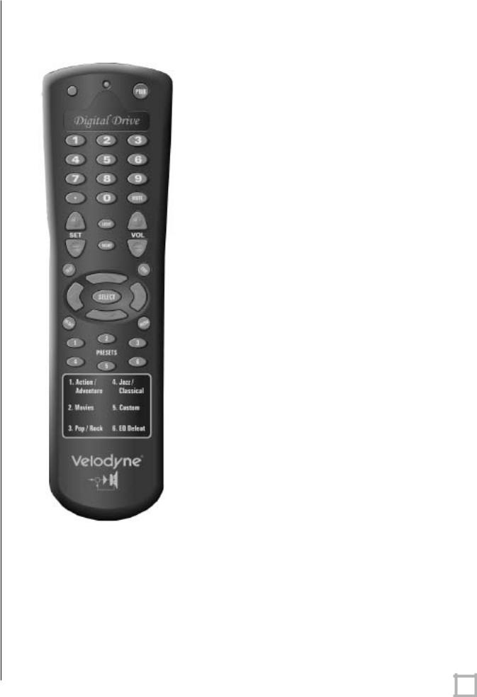
REMOTE CONTROL BUTTONS
A brief description of each button on the remote control follows:
•PWR – Causes woofer to stand by if in “Active” standby mode.
•NUMERIC KEYPAD – Used to enter SETUP mode and for other functions.
•SET (+/-) – Increases or decreases the Q value for a parametric EQ, or sets values on the settings page.
•LIGHT – Turns the subwoofer’s front panel Velodyne logo indicator on or off.
•NIGHT – Limits the peak output of the subwoofer, and illuminates the logo’s amber underlining to signify that the subwoofer is in night mode.
•VOL (+/-) – Raises or lowers the volume of your subwoofer. The blue (Velodyne) light flashes more quickly as the volume increases, and the light blinks out the volume level after you stop adjusting it. For example, for a volume of 34, you would see three long blinks followed by four shorter ones.
•MUTE – Mutes and unmutes the subwoofer.
•TEST – Used to toggle between the settings screen and the system response screen during setup.
•EXIT – To exit SETUP mode. The unit will ask if you want to save settings before exiting.
•SELECT – To toggle field values.
•RESET – Used to reset volume to the last saved setting on the main screen, and to defeat crossovers on the settings screen.
•MENU – Enters SETUP mode from the introductory screen.
•PRESETS – To access the five preset and one EQ defeat listening modes. Initially set at the factory, they are fully user adjustable. The blue (Velodyne) light flashes the appropriate number of times to indicate which preset you have selected (e.g. twice for preset 2).
NOTE: The button in the upper left is not used.
Figure 1: Velodyne Digital Drive remote control
.w w w . v e l o d y n e . c o m |
Digital Drive User’s Manual |
4 |
DIGITAL DRIVE ACCESSORY KIT
The Velodyne Digital Drive Accessory Kit contains the following six components:
•Calibrated precision microphone
•Microphone windscreen cover
•Tabletop microphone stand
•Microphone stand adapter
•25-foot video cable
•25-foot audio cable
•20-foot XLR microphone cable
Installation Overview
Your new Velodyne servo subwoofer provides for a number of installation options. Read all the installation information below in order to determine which installation option is best for your system. Remember to perform all installation procedures with subwoofer unplugged until instructed to activate it!
SUBWOOFER CONTROLS AND POR TS
The Velodyne Digital Drive subwoofer is set up, configured, and adjusted by the controls, inputs, and connections located on the rear panel of the unit. Figure 2 shows the location of each of these important operational interfaces. Brief descriptions of each interface follow.
.w w w . v e l o d y n e . c o m |
Digital Drive User’s Manual |
5 |
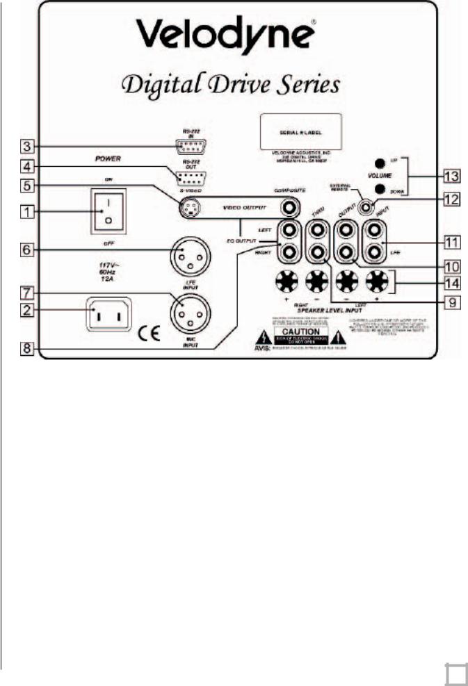
Figure 2: Digital Drive Rear Panel Connections
(1)POWER – Press the POWER switch to the ON position to activate the subwoofer. If the unit is to be left unused for an extended period of time, move this switch to the OFF position to prolong the life of the subwoofer.
(2)POWER RECEPTACLE – Connect your detachable AC power plug to this male interface connection. The detachable cord allows for easy replacement should the original be damaged.
(3)RS-232 IN – Use this port to communicate with your computer (for software updates), a touch panel remote control, or another upstream Digital Drive subwoofer. See Appendix A for an explanation of the use of the serial port, available commands, and their formats.
(4)RS-232 OUT – Use this port to communicate with a second “daisy-chained” Digital Drive subwoofer. Also, the 12V trigger feature requires a 12V trigger signal (polarity irrelevant) across pins 7 and 9 of this port.
(5)EQ VIDEO OUTPUT – Used to display the video generated by the subwoofer. S-Video
or composite connections are available (composite cable included). NOTE: Only |
||
connect to a single video output at a time. |
|
|
.w w w . v e l o d y n e . c o m |
Digital Drive User’s Manual |
6 |

(6)LFE INPUT – This XLR input jack receives the balanced LFE signal from your receiver or processor.
(7)MIC INPUT – This XLR input jack is for your XLR microphone cable.
(8)EQ OUTPUT LEFT/RIGHT – Connect the audio cable from your accessory kit to these jacks: white plug to LEFT, and red plug to RIGHT.
(9)THRU – These RCA connectors are for sharing the same signal that goes into your subwoofer with a second “daisy-chained” subwoofer. RCA input comes out of the THRU jack.
(10)OUTPUT – These RCA connectors incorporate the use of an 80Hz 6dB/octave slope high pass crossover.
(11)LFE INPUT – This RCA input jack is for line-level connection.
(12)REMOTE SENSOR – This connection allows for hook-up of the optional remote control receiver. With the optional receiver plugged in you will be able to utilize all functions of the remote. Place the infrared receiver within direct line of sight from your usual listening position.
(13)VOLUME UP/DOWN – Press the black UP pushbutton to incrementally raise your subwoofer’s system volume; press the black DOWN pushbutton to incrementally lower your subwoofer’s system volume. Note the use of these buttons during software update.
(14)SPEAKER LEVEL INPUT RIGHT/LEFT – This speaker-level connector allows either banana plug/jack or exposed wire/terminal connections.
.w w w . v e l o d y n e . c o m |
Digital Drive User’s Manual |
7 |

Installation – Quick Start
To set up and take advantage of the EQ features in your new Digital Drive subwoofer in the least amount of time, perform the following steps:
1.Unpack the subwoofer and connect the power cable.
2.Connect an LFE input cable from your receiver/processor to the input jack. For other hookup options, see step 2, on the following page.
3.Power up the unit and ensure that it is receiving signal from your receiver (i.e. playing bass).
4.Connect the microphone (in the accessory kit) and place it in your favorite listening position. Then press 3-2-1 on the remote.
5.The unit should emit 25 “sweep” tones then restart and play normally. The subwoofer has now automatically EQ’d itself to your room.
6.Adjust the subwoofer’s volume to taste.
7.Enjoy!
.w w w . v e l o d y n e . c o m |
Digital Drive User’s Manual |
8 |

Installation – Step-by-Step
To ensure a quick and flawless installation of your Velodyne Digital Drive unit, follow these numbered setup instructions in their exact order.
SUBWOOFER CABLE CONNECTIONS
Make all necessary cable connections between the applicable subwoofer connector port and your particular home electronics equipment in the following order:
1.Insert the detachable AC power cord into the 117V~, 60Hz, 15A power interface port on the rear panel of your subwoofer. Plug the male end of the cord into a convenient wall outlet.
2.Provide signal to your subwoofer through one or more of the following connections (refer to your receiver/processor owner’s manual for available inputs to the subwoofer):
a.LFE INPUT (RCA, the RED jack at location 11 on Figure 2) – This is the most common input cable connection. Make a connection between this input and the LFE output or the subwoofer output of your receiver or processor; OR
b.LFE INPUT (XLR, location 6 on Figure 2) – Make a connection between this input and the balanced LFE outputs of your receiver or processor; OR
c.INPUT, LEFT and RIGHT (location 11 on Figure 2) – Make a connection between these inputs and the stereo outputs of your receiver or processor; OR
d.SPEAKER-LEVEL INPUT (location 14 on Figure 2) – Make a connection between these inputs and the left and right speaker connections on your receiver or processor. Make this connection by either inserting speaker wire into the correct binding post terminals or by removing the banana plug jack caps and inserting banana plug wire into the jacks.
NOTE: Refrain from routing connections permanently at this time to accommodate subwoofer room placement as described below.
3.Establish the line-level connection (optional). Connect to a pre-amplifier’s main outputs and returning them to your amplifier inputs. When installed in this fashion, your satellite speakers will be crossed over at 80Hz, which removes the lower bass from your amplifier and speakers, enabling them to do a better job reproducing high frequencies. By utilizing this method, you will have a bi-amplified system, gaining improved power and headroom for your system.
A Wor d About Subwoofer Outputs
The Velodyne subwoofer is designed to operate using the full range audio signal for input when using the digital built-in crossover. Most processors/receivers have a “subwoofer out” jack that is internally filtered and designed to be used with a conventional amplifier and speaker. In some rare cases, combining both an external crossover and the one internal to the subwoofer may result in low output and increased noise. In these installations you may need to bypass the internal crossover in either the processor or Velodyne subwoofer. In some installations, simply setting one crossover to a higher frequency (such as 120Hz) will restore maximum performance. To bypass the subwoofer’s internal crossover when the unit is being fed a low pass signal from another crossover, refer to the SETUP instructions at step 14 (page 24).
Note: If not using an |
external |
crossover, |
you |
should |
use |
the |
built-in |
crossover |
for |
optimal performance. |
|
|
|
|
|
|
|
|
|
.w w w . v e l o d y n e . c o m |
|
|
|
|
Digital Drive User’s Manual |
9 |
|||

4.Referring to Figure 2, Locations 5 and 8, connect the audio/video cable between your subwoofer (EQ OUTPUT VIDEO/LEFT/RIGHT yellow, white, and red respectively) and your electronics (receiver, processor, TV, etc.). Insert the color-coded cable plugs into the correct EQ OUTPUT receptacle – the yellow plug into the VIDEO jack, the white plug into the LEFT jack, and the red plug into the RIGHT jack. The opposite ends of this cable should be connected to your receiver/processor. The yellow VIDEO cable goes to an available composite video input (e.g. aux), and the white/red AUDIO (L&R) cables go to a corresponding audio input. Consult your receiver/processor and/or TV owner’s manual for more information.
NOTE: Make sure the audio output goes into your AUDIO system, not your TV! The subwoofer will generate test tones used to match the subwoofer to your satellites and to correct for room anomalies that need to be played over your main audio system.
5.Insert the XLR microphone cable’s 3-pin male plug into the MIC INPUT jack (location 7 on Figure 2) on the back panel of the subwoofer. For DD-15 and DD-18 units, a microphone jack is also located on the front of the unit for convenience.
6.Slide the microphone (male connector end first) down through the open, circular sleeve of the tabletop microphone stand. Position this assembly at a desired listening position from your subwoofer.
NOTE: The Digital Drive Accessory Kit includes a microphone stand adapter (1/2”-27 thread) for use with professional mounting stands. Be sure to first remove the inner thread piece (3/8”-16) before using.
7.Connect the XLR microphone cable’s female jack end with the male connector end of the microphone.
8.Sheath the microphone pickup with the foam windscreen cover as a protection against dirt and airborne contaminants.
A Wor d About Inter connect Cables
When installing your new Velodyne subwoofer using the line level connections, you should always use shielded phono cables. There are many quality cables available today, most any of which will work perfectly well. We do recommend that you keep the length of cable as short as possible to avoid any potential noise problems.
When routing cables, try to keep them away from equipment that generates significant noise such as industrial or digital equipment.
A Wor d About Connecting Mor e Than One Subwoofer
If you are connecting more than one DD subwoofer to your system, you will connect them |
|
together in a “daisy-chain.” Choose one sub for all the connections described below (we’ll call |
|
this the “master” sub), and then connect an RCA jack from the THRU RCA jacks of the “primary” |
|
to the input jacks of the “slave” sub. You will also need to obtain a “Mouse Extension” serial |
|
cable (available at any computer store, from your Authorized Velodyne dealer, or from Velodyne |
|
directly) and connect the RS-232 OUT port of the primary sub to the RS-232 IN port of the |
|
secondary sub. Then, all runtime commands directed at the primary sub (such as volume) will |
|
be communicated to the secondary sub automatically through the serial cable. If you have more |
|
than two subs in your setup, simply continue the daisy chain from the secondary sub to the next |
|
sub in the line (using both RCA and serial connections) and so on. |
|
.w w w . v e l o d y n e . c o m |
Digital Drive User’s Manual 10 |

NOTE: When a DD subwoofer detects an incoming RS-232 command, it reverts to “Slave Mode.” This means that the subwoofer will no longer accept IR commands. To reestablish normal operations, remove the RS-232 cable and power cycle the unit.
Note that the daisy chain connection ONLY allows the woofers to communicate basic “run-time” commands such as volume and preset. We recommend the following sequence when setting up daisy-chained subs.
1.First, connect only the master sub to the system. Do not connect the thru or serial cables at this time.
2.Establish the crossover, phase, and other settings EXCEPT the EQ on the master sub (see setup steps 1 – 17 starting on page 17). Note the low pass crossover, phase and polarity settings, then save.
3.Connect the video out of the slave subwoofer, go to the settings screen, establish the low pass crossover, slope, phase, polarity, and night mode settings from the master subwoofer, then save settings. Repeat for each slave subwoofer in your system.
4.Connect the microphone to the slave subwoofer and use the “self-EQ” feature (described on page 12) to establish room EQ for that subwoofer.
5.Repeat steps 3 and 4 for each slave subwoofer in your system.
6.Reconnect the video out to the master subwoofer, and reconnect the thru and serial cables so that the master and slave subwoofer(s) are daisy chained.
7.EQ the primary subwoofer (see steps 8-25 starting on page 20). Self-EQ is NOT recommended for the primary subwoofer.
8.Setup is complete!
A Wor d About Setting Up Your Receiver/Pr ocessor For Optimal Subwoofer Per for mance
It is important that your receiver/processor (from now on we’ll refer to this as your “receiver” for simplicity) be set up correctly to work in concert with your DD subwoofer. In the receiver’s “speaker set up” menu you will enter the number of speakers and indicate whether or not you have a subwoofer. In addition you will enter the speaker size, usually “large” or “small.” It is almost always advantageous to use the “small” setting. Most full-range speakers use smaller woofers for the bass section and typically do much better in the upper bass and lower midrange if relieved of deep bass duties. Your DD subwoofer, with its 1250 Watt RMS amplifier, large magnet and voice coil, and servo control, can play 80Hz and below more accurately, with more power and with lower distortion than a full range loudspeaker can. This is often referred to as “bi-amping” a system. Setting your speakers to “small” in your receiver also means the receiver’s bass management will send bass to the subwoofer in all playback modes, 2-channel or surround.
When you choose “small” you activate the receiver’s crossover. Some receivers will offer crossover choices. In this case a good rule of thumb is double the low number of the stated frequency response of your main speakers. So if a speaker’s response is rated from 40Hz –18KHz, then doubling the 40Hz low frequency number equals 80Hz. In this example 80Hz would be a good crossover point. When in doubt, 80Hz is always a good starting point. Those that do not offer choices normally crossover at 80Hz, which is an excellent crossover point, and is also the THX™ standard.
If you use this “small” speaker set up recommendation go into the DD’s “SYSTEM SETTINGS” |
||
screen and turn the DD’s crossover “OFF” (see page 26). |
|
|
.w w w . v e l o d y n e . c o m |
Digital Drive User’s Manual |
11 |
 Loading...