

Page 1
SET UP
SER INTERFACE MANUAL
U
LUS
Digital Drive
P
DD-10+, DD-12+, DD-15+ and DD-18+
Page 2

1
INTRODUCTION
1
Introduction
1
Manual Organization
2
PART ONE - WINDOWS
SER INTERFACE
U
FOR OPTIMIZATION
(RECOMMENDED INTERFACE)
Virtual COM Port Driver
2
PLUS
Velodyne’s Digital Drive
2
Software Installation Requirements
3
Installing the USB Virtual COM Driver and the Digital
3
10
PLUS
Drive
Windows Setup Program
Digital Drive
PLUS
Windows Setup Program
Windows Setup Software
User Interface
10
11
11
11
12
12
12
12
12
13
13
Frequency Response and Parameters Screen
Graphs
Optimization Parameters
EQ Optimization Option Selection and Initiation
Save Setting Options
Subwoofer Controls
Status Information
Menu
Screen Navigation
Preset Screen
Establishing Communication between the Digital
PLUS
Drive
Subwoofer and the Digital Drive
Windows Setup Program
14
Making & Saving Preset Changes
Running Self-EQ Optimization– Your First EQ
14
PLUS
Running Auto-EQ
15
Optimization – Stepping
Up in Power
Running Manual EQ Optimization– Adjust it to
15
Your Liking
Troubleshooting Guide
17
s Digital Drive
Uninstalling V
17
Uninstalling the Virtual Com Port Software
19
elodyne’
PLUS
PLUS
Windows
PART TWO - TV SCREEN USER
1
2
INTERFACE FOR OPTIMIZATION
Instruction Conventions
1
2
Make Video Connection between TV and Subwoofer
21
21
creens
S
1
2
23
23
23
24
24
24
24
25
25
26
27
27
28
28
29
29
30
31
32
Introductory Screen
System Response Screen
Status Messages
Screen Navigation
System Settings Screen
Screen Navigation
Screen Controls
Tips for Using the TV Screen Controls
Remote Control Button Commands
Go to the System Response Screen
Go to the System Settings Screen
Lock the Setup Preset
Restore Defaults
Save Settings
Select a Preset
Make & Save Preset Changes
Change Default Preset
Set Parametric Equalizer Filter Parameters
Running Self-EQ Optimization – Your First EQ
PLUS
Running Auto-EQ
Optimization – Stepping
Up in Power
33
Running Manual EQ Optimization–
to Your Liking
34
34
34
35
35
36
37
Perform Listening Test
Introductory Screen Runtime Inactive Modes
Standby Mode
Power Off Mode
Waiting for 12 Volt Input Mode
s Low Pass Crossover Filter
Defeat Subwoofer
’
PART THREE - SOFTWARE &
DRIVER UPDATES
Adjust it
Page 3

INTRODUCTION
igital Drive
D
INTRODUCTION
ne of the advanced features of your Digital Drive
O
PLUS
Auto-EQ
rive
D
and Manual-EQ. You can use all the optimization methods, except Manual-EQ, without either of the user interfaces for Digital
PLUS
ptimization. However, if you want to use Manual-EQ optimization you need to use one of the user interfaces. Also, if you want to
o
view your subwoofer’s frequency response and/or parameter settings, you need to use a user interface.
PLUS
ubwoofer is the available options for optimizing the bass output, including Self-EQ,
s
LUS
P
ser Interface Manual
U
efer to the Digital Drive
R
PLUS
ser’s Manual for information about the Self-EQ, Auto-EQ
U
PLUS
nd Manual-EQ optimization methods and the
a
parameters each optimizes, descriptions of the parameters that can be optimized manually, and a recommended order to adjust parameters
uring Manual-EQ optimization.
d
For your convenience, Velodyne provides the following two user interfaces for performing optimizations:
LUS
• Velodyne’s Digital Drive
computer. This program is sometimes referred to by the shorter name of
P
Windows Setup Program: (Velodyne recommended interface) Software that runs on a Windows
Windows interface. The software is used to:
- Control and display preset EQ and parametric filter settings
PLUS
- Initiate Self-EQ, Auto-EQ
and Manual-EQ optimizations
- Display the subwoofer’s frequency response curve
- Display the parametric filter curves
PLUS
- Save and open Digital Drive
files with subwoofer’s settings and for Manual-EQ only, the frequency response
curve that results from these settings
- Save settings to the subwoofer’s memory
• TV Screen Display and Remote Control Commands: This combination is often referred to by the shorter name of
TV Screen interface because settings and command choices are shown on your TV screen. The TV screen interface and
remote control can be used together to:
- Control and display preset EQ and parametric filter settings
LUS
P
- Initiate Self-EQ, Auto-EQ
and Manual-EQ optimizations
- Display the subwoofer’s frequency response curve
- Display the parametric filter curves
- Save settings to the subwoofer’s memory
MANUAL ORGANIZATION
You need to only use one interface for optimization or viewing of settings and frequency response curves. We recommend the Windows
interface as it is usually much easier to connect your subwoofer to your computer than to your TV screen. Also, the Windows interface
allows you to see the parametric filter curves and save settings to files on your computer. These features aren’t available with the TV
screen interface. Because you only need to use one interface, skip to the part of this manual that covers the interface you want to use:
• Part One - Windows User Interface for Optimization (Recommended Interface)
OR
• Part Two - TV Screen User Interface for Optimization
The final part of this manual covers how to update the driver, software, bootcode and firmware.
• Part Three - Software & Driver Updates
[ 1 ]
Page 4

LUS
ART ONE — WINDOWS INTERFACE FOR OPTIMIZATION
P
igital Drive
D
P
ser Interface Manual
U
PART ONE -
indows Interface for Optimization
W
(Recommended Interface)
n order to use the Windows interface to perform any setup or optimization of your Digital Drive
I
need to be installed on your computer:
• USB Virtual COM Port Driver
Velodyne’s Digital Drive
•
oth pieces of software can be fully uninstalled using normal Windows procedures as described later in this document, leaving your
B
PLUS
indows Setup Program
W
computer in its former state.
This part of this document covers:
• The purpose of the driver and program.
• The computer requirements for installing this driver and program.
• How to install and uninstall this driver and program.
• How to connect your subwoofer and the Windows Setup Program so that they communicate and share data.
• How to troubleshoot connection issues between your subwoofer and the Windows Setup Program.
• How to use the Windows Setup Program controls to modify and save subwoofer parameters.
PLUS
• How to run Self-EQ and Auto-EQ
optimization using the Windows Setup Program.
• How to use the Windows Setup Program to perform Manual-EQ optimization.
• How to update the USB Virtual COM Port driver, the Velodyne Digital Drive
PLUS
Digital Drive
subwoofer bootcode and the Velodyne Digital Drive
PLUS
Windows Setup Program, the Velodyne
PLUS
subwoofer firmware.
PLUS
ubwoofer, the following two programs
s
CAUTION: Since the DD+ subwoofer is a USB device, there is more to connecting the subwoofer to your PC than simply installing the USB
LUS
P
cable. You should always connect the subwoofer to the PC right after running the Velodyne Digital Drive
Windows Setup Program CD
to allow Windows to recognize the subwoofer and complete driver configuration and installation.
Virtual COM Port Driver
The USB Virtual COM Port driver allows the Digital Drive
though it connects with a USB port. The Digital Drive
PLUS
subwoofer to appear as though it was connected through a COM port even
PLUS
subwoofer communicates usually through a COM port, such as the two RS-232
connectors on the back of your subwoofer. Because most modern computers have USB ports instead of COM ports, you need to convert
one of your computer’s USB ports to a COM port. Instead of having to physically perform this conversion with hardware, you can use the
USB Virtual COM Port driver to virtually perform the conversion.
Velodyne’s Digital Drive
elodyne’
V
s Digital Drive
PLUS
PLUS
Windows Setup Software
Windows Setup Software is the Windows computer interface for adjusting your subwoofer
s parameters.
’
This interface displays the same information and allows for the same parameter adjustments as the TV screen interface. However,
with this interface you don’t need to access the video input connections to your TV that are often hard to reach in an already installed
home theater system.
[ 2 ]
Page 5
WINDOWS INTERFACE FOR OPTIMIZATION
Software Installation Requirements
The USB Virtual COM Port software and Velodyne’s Digital Drive
nd minimum hardware as shown in the table below.
a
indows Setup Software and USB Driver
W
Minimum Hardware and Operating System Requirements
Supported Windows XP SP2
Operating Systems Vista SP1
RAM (Memory) 1 GB RAM
Processor Speed 1 GHz single core
Available Hard Drive Space 5 MB
Display Resolution 800 x 600
LUS
igital Drive
D
PLUS
Windows Setup software require the Windows operating systems
P
ser Interface Manual
U
32-bit and 64-bit Home and Professional versions of:
Windows 7
Note: Velodyne’s Digital Drive
PLUS
Windows Setup software was not designed to operate in any Mac, Linux, or virtual machine operating
systems. Often in virtual machine operating systems, such as VM Ware and Parallels for Mac, the operating system can’t recognize devices
connected to the computer’s USB and COM ports. Hence, your computer can’t communicate with the Digital Drive
PLUS
subwoofer from within
a virtual machine.
LUS
Installing the USB Virtual COM Driver and the Digital Drive
LUS
The Velodyne Digital Drive
PLUS
Digital Drive
Windows Setup Program with minimal user guidance. However, for the Digital Drive
P
Windows Setup Program CD is designed to perform the installation of both the USB Virtual COM driver and the
P
Windows Setup Program
PLUS
Windows Setup Program you can
choose your installation language and the location to install the software.
To install the driver and software:
The images included in this procedure are from an installation done on a Windows 7 computer. Due to dif
ferences in the various Windows
operating systems, your install experience may vary slightly from the one presented here.
Make sure your computer is on and that you can see your Windows desktop. The subwoofer should NOT be connected to
1)
the subwoofer yet.
2) Save your work and close running application programs, open browser windows and other open screens.
PLUS
3) Insert the Velodyne Digital Drive
Windows Setup Program CD into your computer’s compatible disc drive.
4) The disc auto plays and begins installing the USB Virtual COM Port driver. It may take up to 10 seconds for the auto play
to begin depending on your computer
.
[ 3 ]
Page 6
LUS
WINDOWS INTERFACE FOR OPTIMIZATION
igital Drive
D
P
U
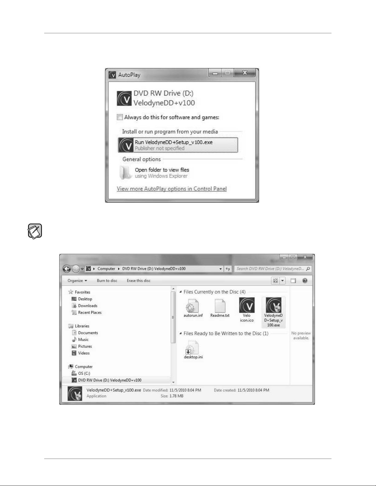
5) In Windows 7, if you see an AutoPlay dialog window as shown below, click Run VelodyneDD+Setup_v###.exe under
the text that reads “Install or run program from your media.”
ser Interface Manual
If the install program doesn’t start automatically, you can start the installation by double-clicking on the
VelodyneDD+Setup_v###.exe file in
the CD directory in Windows Explorer as shown below. ### represents the version number of the software, such as 100.
[ 4 ]
Page 7
LUS
WINDOWS INTERFACE FOR OPTIMIZATION
igital Drive
D
P
ser Interface Manual
U
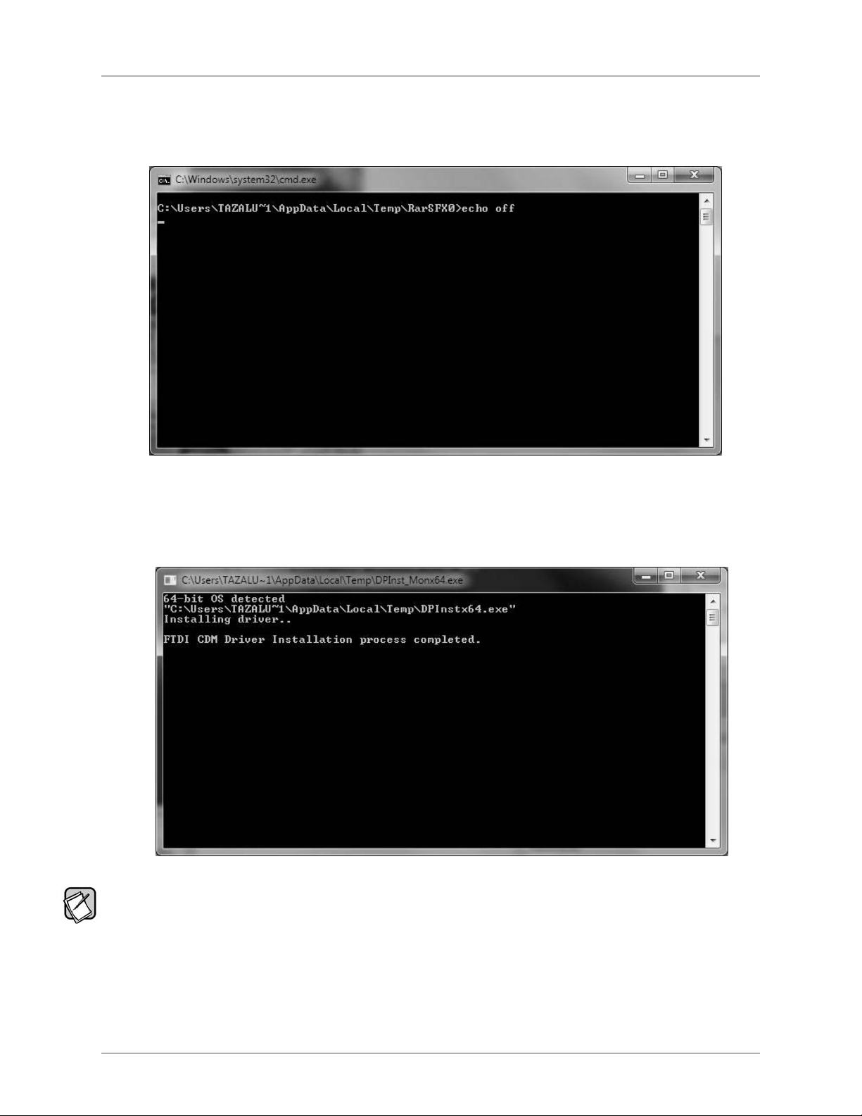
6) The driver install is performed in a black background command prompt window. It begins by displaying the echo off message as
shown below.
7) The driver install can take anywhere from a few seconds to a few minutes, depending on the configuration of your computer. When the
driver install finishes, the
key to continue.” The installation of the Digital Drive
FTDI CDM Drive Installation process completed message appears and you are prompted to “Press any
PLUS
Windows Setup Program Setup Wizard does not start until you press a key.
If after a few minutes, the message indicating the install is complete doesn’t appear and you still see the window as shown in Step 7, the
driver installation may need to be re-started. To re-start, first close the driver installation window. Next, eject the CD and go back to Step 4.
[ 5 ]
Page 8
WINDOWS INTERFACE FOR OPTIMIZATION
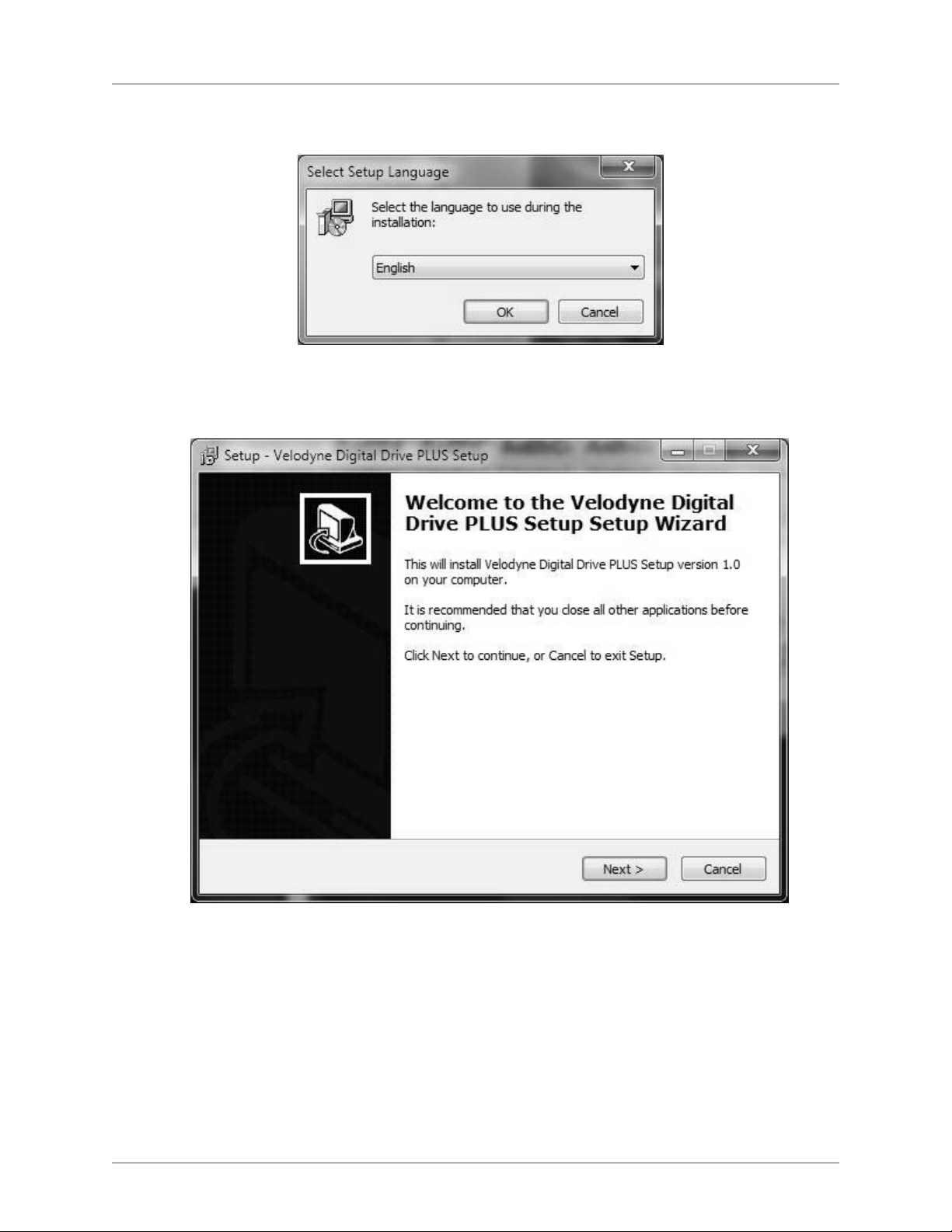
8) The Select Setup Language dialog window opens. Select an install language and then click OK.
igital Drive
D
LUS
P
ser Interface Manual
U
9) The Velodyne Digital Drive
PLUS
Setup Program Wizard opens. Click Next to continue.
[ 6 ]
Page 9
LUS
WINDOWS INTERFACE FOR OPTIMIZATION
igital Drive
D
P
ser Interface Manual
U
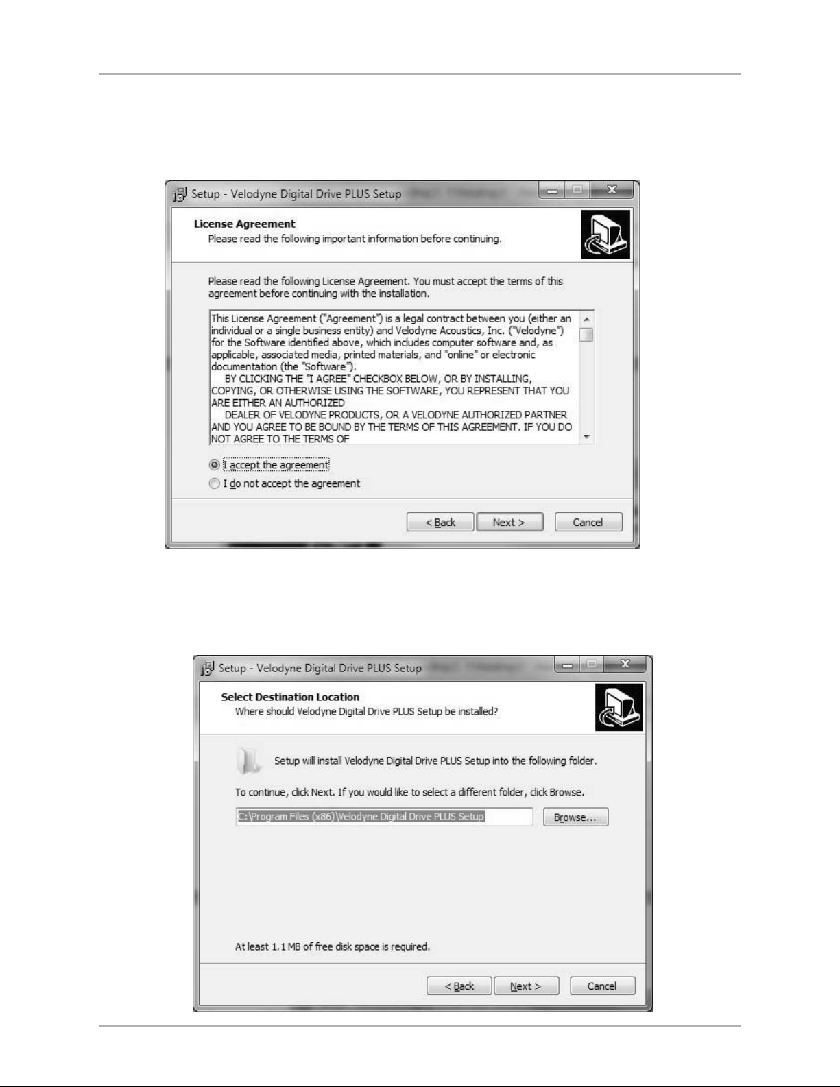
10) Read the EULA (End User License Agreement), then select the I accept the agreement option. You have to accept the EULA to
continue with the software installation.
1) Click
1
ext
N
.
12) Browse to where you want to install the Digital Drive
Program Files folder.
13) Click
Next.
PLUS
Windows Setup Program. The default location is your Windows
[ 7 ]
Page 10
WINDOWS INTERFACE FOR OPTIMIZATION
igital Drive
D
LUS
P
ser Interface Manual
U
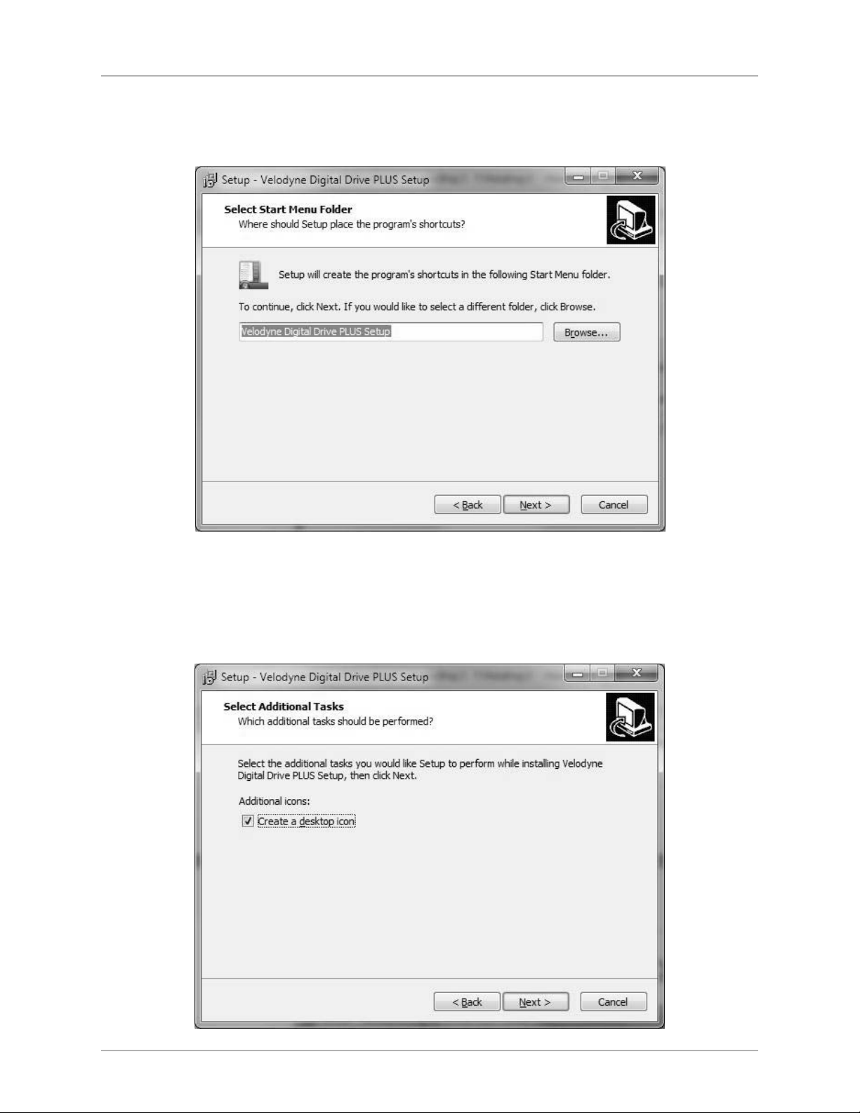
14) Browse to where you want the program to appear in your Start Menu. The default folder is Velodyne Digital Drive
15) Click
Next.
PLUS
Setup.
16) If you don’t want the installation to create a desktop icon for the Digital Drive
a desktop icon
17) Click
Next.
option. By default a desktop icon is created.
PLUS
Windows Setup Program, un-check the Create
[ 8 ]
Page 11
WINDOWS INTERFACE FOR OPTIMIZATION
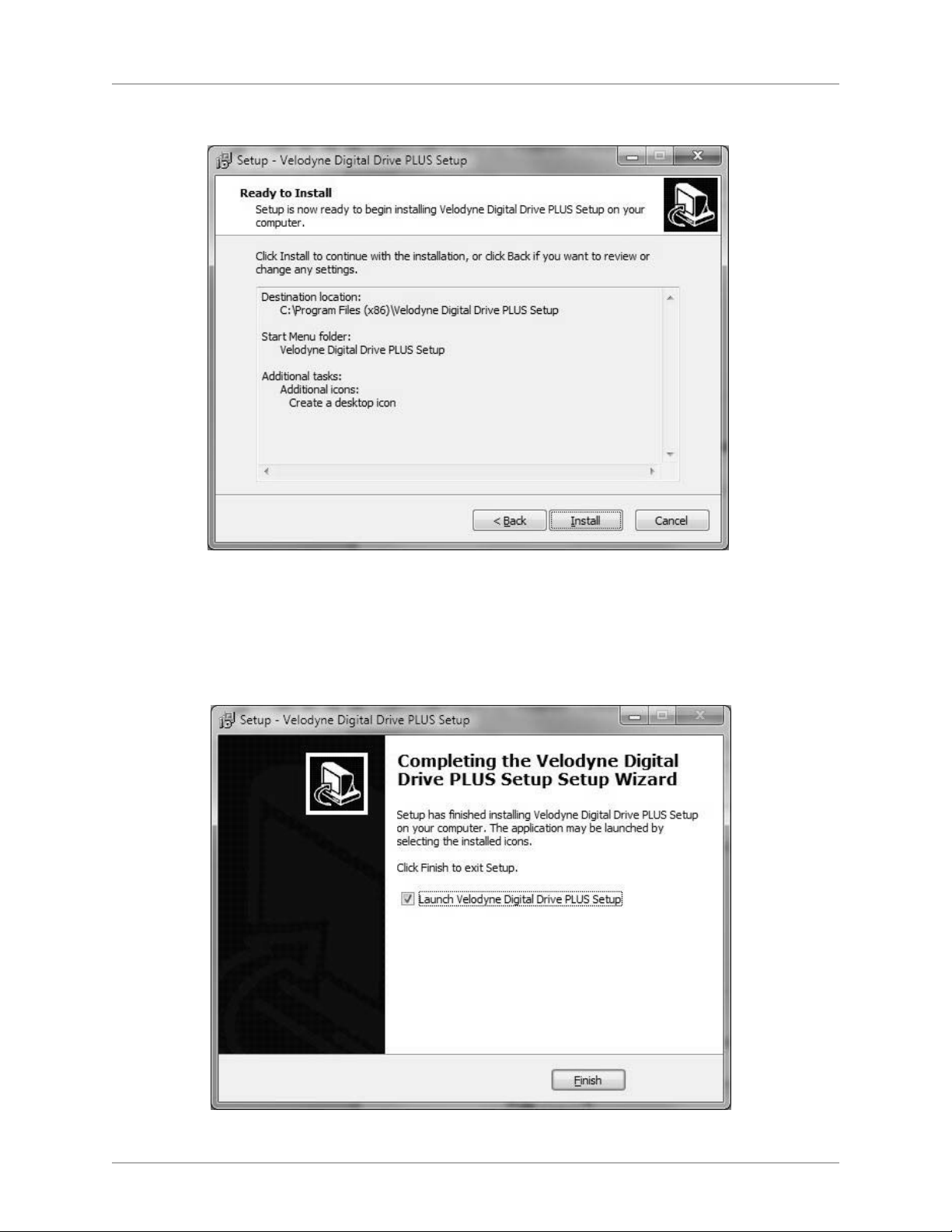
18) Click Install.
igital Drive
D
LUS
P
ser Interface Manual
U
19) If you want to run the Digital Drive
20) Click
Finish.
PLUS
Windows Setup Program now, select the Launch Velodyne Digital Drive
PLUS
Setup option.
[ 9 ]
Page 12
WINDOWS INTERFACE FOR OPTIMIZATION
igital Drive
D
LUS
P
ser Interface Manual
U
21) You should now connect your Digital Drive
PLUS
subwoofer to the computer with the supplied USB cable, making the subwoofer is
powered on. This allows Windows to finish the driver installation.
2) You can now begin using the software to set the equalization parameters for your subwoofer.
2
fter the installation of the Virtual COM Port software, your computer thinks the USB cable from your computer to the Digital Drive
A
PLUS
s really
i
a serial cable connected to a COM port.
You can see the COM port number assigned to the USB port by using the Windows Control Panel’s System > Hardware > Device Manager.
The virtual port appears as an additional COM port with the label "USB Serial Port."
LUS
DIGITAL DRIVE
P
WINDOWS SETUP PROGRAM USER INTERFACE
This section describes the controls and features available in the two user interface screens in the Windows Setup Program:
• Frequency Response and Parameters screen
• Preset screen
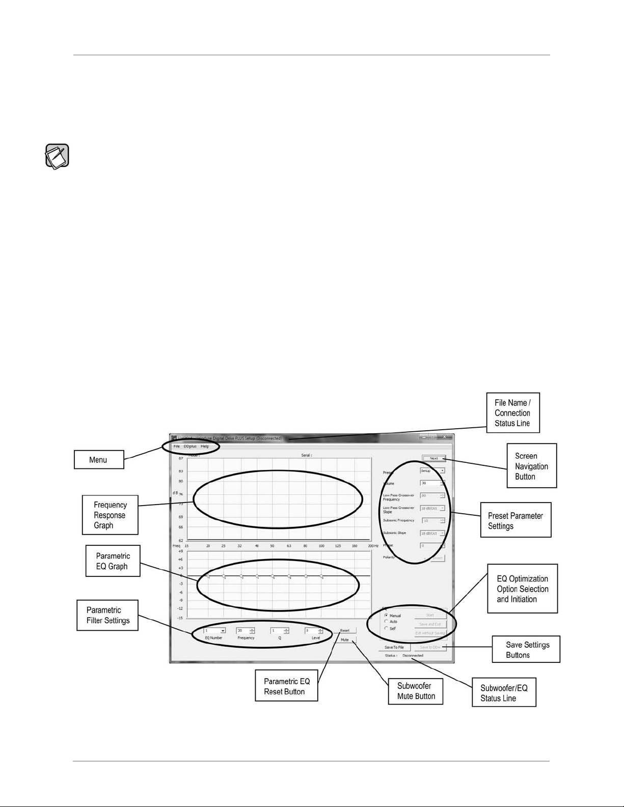
Frequency Response and Parameters Screen
LUS
When you run the Digital Drive
P
Windows Setup Program it opens to the Frequency Response and Parameters screen. This screen is the
screen you’ll use most often when optimizing the bass response.
The main functional areas of the screen are indicated in the following image. The features available in each of these areas are described
after the image.
Figure 1: The Frequency Response and Parameters Screen
[ 10 ]
Page 13

LUS
WINDOWS INTERFACE FOR OPTIMIZATION
igital Drive
D
P
ser Interface Manual
U
Graphs
• Frequency Response Graph: Displays the measured frequency response. Both the horizontal and vertical scales are fixed.
arametric EQ Graph:Displays the graphical representation of the 8 adjustable parametric EQ filters based on the
•
P
Parametric Filter Settings.
Each diamond represents one of the eight parametric filters. The small number by each indicates the EQ number of the
-
parametric filter that diamond represents.
The filters are numbered 1 to 8 from left to right.
-
- The green line is the curve for a single parametric filter.
- The blue line is the summation of all parametric filter EQs.
- After one complete sweep tone, the frequency response updates.
- You can use the mouse to grab and drag the filter to a new frequency and level. Moving the diamond up and down changes the
level of boost or cut. Moving it side-to-side changes the frequency of the selected EQ filter.
- Once a parametric filter’s EQ graph has a peak or dip, you see a horizontal line with small diamond handles appear through the
latest filter at the maximum or minimum level. Moving one of the diamonds at the end of this line towards the filter center diamond
raises the filter Q, narrowing the bandwidth. Moving it away from the filter center diamond widens the bandwidth lowering the Q.
- If you change a filter’s settings using this graph, the changes are shown in the
Parametric Filter Settings area.
Optimization Parameters
s settings.
• Parametric Filter Settings: Displays and allows you to adjust each of the parametric filter
either single-increment mouse clicks or direct entry of a value. If you adjust a filter
are reflected in the
•
Preset Parameter Settings: Displays and allows you to adjust the values of a selected preset with single-increment mouse clicks or
Parametric EQ Graph.
’
s settings using these input fields, the changes
’
You adjust the settings using
direct entry of a value.
EQ Optimization Option Selection and Initiation
The options and buttons in this area allow you to select and start an optimization option for the connected subwoofer
•
Manual: Manual-EQ optimization.
Auto: Auto-EQ
•
•
Self: Self-EQ optimization.
•
Start: Begin the selected optimization.
PLUS
optimization.
.
[ 11 ]
Page 14

LUS
WINDOWS INTERFACE FOR OPTIMIZATION
igital Drive
D
P
ser Interface Manual
U
Save Setting Options
• Save to File: Save the current settings in the program to an EQ optimization profile file on your computer. Same as the File >
ave As
S
•
Save to DD+: Loads the current settings or loaded EQ optimization profile in the Digital Drive
igital Drive
D
subwoofer is not synced as long it is communicating with the Digital Drive
eset:Reset all of the parametric filters to their factory default settings, which produces a flat line (level=0 dB, ISO frequencies,
•
R
Q=4.3) as the
enu selection.
m
PLUS
Windows Setup Program into the
PLUS
ubwoofer, memory but the subwoofer doesn’t reboot. You can save settings to the subwoofer even when the
s
PLUS
Windows Setup Program.
Parametric EQ Graph. ISO (International Organization for Standardization) frequencies are standard frequencies
used in the audio industry for EQ.
•
Save and Exit: (Used in EQ process only) Saves EQ results to the subwoofer’s memory and then reboots the subwoofer.
Exit without Saving (Used in EQ process only): Exit EQ mode without saving settings to a file or to the subwoofer.
•
Reboots the subwoofer.
Subwoofer Controls
• Mute: Mute the subwoofer to see the low end frequency response of the satellites of the audio system to which the
PLUS
Digital Drive
subwoofer is matched to.
Status Information
• Filename/Connection (title bar): Shows the name of the settings file after it has been saved to the computer as well as
connection status of the subwoofer.
Subwoofer/EQ (lower right): Displays the subwoofer connection as well as various status updates within the EQ
•
optimization processes.
Menu
• File Menu:
- Open: Open a subwoofer setup profile file.
Save: Save a subwoofer setup profile file as a DDP file.
-
-
Save As: Save a subwoofer setup profile file with an additional name, or to a different place.
Exit: Close the program without saving settings to a file or to the subwoofer.
-
DD+ Menu:
•
- Reconnect: Try to re-connect to the subwoofer.
Save to DD+: Save the current settings to the connected subwoofer
-
Restore Defaults: Restore the Digital Drive
-
Help Menu:
•
- About: Display the software Digital Drive
latest version of the software that is available on the V
Screen Navigation
• Next: Allows you to open the Preset screen
PLUS
subwoofer to its factory default settings.
PLUS
Windows Setup Program version.
elodyne website.
ou can use this to determine if you have the
Y
[ 12 ]
Page 15

LUS
WINDOWS INTERFACE FOR OPTIMIZATION
igital Drive
D
P
ser Interface Manual
U
Preset Screen
The Preset screen allows you to view and modify the volume, low pass crossover frequency and slope, subsonic filter frequency and slope,
hase, and polarity of the presets including the Setup, or global, preset. The Preset screen also allows you to modify the contour frequency
p
and level, and servo gain for each preset. This screen also allows you to set the Night mode percentage and the auto-on setting.
Figure 2: The Preset Screen
• Screen Navigation:
- Previous: Allows you to return to the Frequency Response and Parameters screen.
Establishing Communication between the Digital Drive
PLUS
Digital Drive
Start the Velodyne Digital Drive
1)
Windows Setup Program
PLUS
Windows Setup Program using either the desktop shortcut icon or selecting it from the
PLUS
Windows Program menu.
Subwoofer and the
[ 13 ]
Page 16

WINDOWS INTERFACE FOR OPTIMIZATION
igital Drive
D
LUS
P
ser Interface Manual
U
2) Connect your subwoofer’s front panel USB port to your computer using the supplied USB cable. Refer to the Digital Drive
User’s Manual for directions on how to remove the subwoofer’s front grille to access the USB port.
3) The program establishes communication with the subwoofer and indicates this by displaying
n the program’s title bar and in the lower left corner of the window in the Subwoofer/EQ Status Line
i
4) Once communication is established, the subwoofer model and serial number appear at the top of the
raph
rea.
G
a
Connected or Connected, Not Synced
.
Frequency Response
5) Once you see the Connection message, you can use the program to control the subwoofer.
6) See the Troubleshooting section of this part of the manual if you don’t see the Connection message.
LUS
Refer to the Digital Drive
P
User’s Manual for more information about the different optimization methods and setup options.
MAKING & SAVING PRESET CHANGES
The simplest customization of parameters you can do is to make and save changes to the presets.
You can modify the preset parameters either in the
or on the
night mode and power on settings. The
Preset screen. The Preset screen has the advantage that you can see settings for all the presets at one time and also modify the
Frequency Response and Parameters screen has the advantage that you don’t have to open the
Preset screen.
See the Digital Drive
PLUS
User’s Manual for a detailed explanation of the preset parameter settings that you can modify.
Preset Parameter Settings area on the Frequency Response and Parameters screen
PLUS
To modify the presets using the
1) On the
Frequency Response and Parameters screen, click Next (upper right hand corner).
Preset screen:
• Some values are changed with pull-down menus, like the slopes, whereas others increment with up/down buttons.
• The parameter input fields can also be selected with the mouse and the value typed into them.
Previous to return to the Frequency Response and Parameters screen.
2) Click
Save to DD+ to save the preset setting changes to the subwoofer’s memory.
3) Click
Save to File to save the preset changes to a file on your computer. Velodyne recommends this practice as a way to “back up
4) Click
your work” and to be able to retrieve subwoofer settings without having the subwoofer connected to your computer. You can also save
the settings using the
To modify the presets using the
Preset Parameter Settings area use the Preset pull down menu to select which preset to modify.
1) In the
File > Save menu option. Previously saved profile files can be retrieved using the File > Open menu option.
Frequency Response and Parameters screen:
2) Use the pull down menus to change the preset parameter settings.
3) Click
Save to DD+ to save the preset setting changes to the subwoofer
Save to File to save the preset changes to a file on your computer.
4) Click
s memory.
’
RUNNING SELF-EQ OPTIMIZATION– YOUR FIRST EQ
The easiest EQ optimization to perform is the Self-EQ. With Self-EQ the subwoofer generates its own sweep tone.
To perform Self-EQ optimization:
1) Remove the microphone, mic cable and stand from the accessory kit. Carefully snap the microphone into the stand and attach the
PLUS
larger end of the cable to it. See the Digital Drive
2) Place the microphone at the main listening position.
3) Attach the small end of the mic cable to the jack on the left side of the subwoofer front control panel.
4) Make sure the subwoofer is on and your audio system is of
User’s Manual for more information.
f.
[ 14 ]
Page 17

LUS
WINDOWS INTERFACE FOR OPTIMIZATION
igital Drive
D
P
ser Interface Manual
U
5) On the Frequency Response and Parameters screen, select the Self option in the EQ Optimization Option Selection and
Initiation
6) Click
) The subwoofer produces its own sweep tone and its frequency response.
7
8) You can watch the subwoofer smooth its frequency response by adjusting the parametric EQ filter levels on the
R
area.
Start.
esponse and Parameters
Frequency
creen. Self-EQ doesn’t change the Setup preset parameters (volume, crossover, etc.) Self-EQ
s
uses a 160 Hz crossover.
9) When Self-EQ finishes, the front subwoofer display shows End for 10 seconds, then the subwoofer reboots by turning itself off and
back on. The display shows the preset number and then volume level. During this process the new filter settings are saved into the
subwoofer’s memory.
10) Click
The frequency response curve is only saved with Manual-EQ, not Self-EQ or Auto-EQ
RUNNING AUTO-EQ
The next level up in the Digital Drive
Save to File to save the Setup preset’s EQ filter settings to a DDP file on your computer.
LUS
P
.
LUS
P
OPTIMIZATION – STEPPING UP IN POWER
LUS
P
EQ optimization methods is Auto-EQ
LUS
P
optimization. To perform Auto-EQ
LUS
P
optimization:
1) Set up the microphone as in the Self-EQ instructions above.
2) Make sure the subwoofer and your audio system are both on.
PLUS
3) Place the Digital Drive
Sweep Tone CD into your disc player and press play.
4) Once the sweep tone starts to play, adjust the receiver or processor output level to about the level of a normal-loudness conversation.
5) On the
6) Click
Frequency Response and Parameters screen, select the Auto option in the EQ Optimization Option Selection
and Initiation
area.
Start.
7) The subwoofer not only adjusts the Setup preset EQ filter parameters as you watch, but it also adjusts the volume, crossover, slope,
and phase while these input fields are grayed out during the Auto-EQ
PLUS
optimization process.
8) You can also watch the status of the subwoofer in the process down in the lower right in the subwoofer/EQ status line.
PLUS
9) When Auto-EQ
optimization finishes, the front display shows End for 10 seconds, the subwoofer reboots by turning itself off
and back on. The display shows the preset number and then volume level. During this process the new filter settings are saved
PLUS
into the subwoofer’s memory. When the subwoofer is rebooting, the Digital Drive
subwoofer is
Disconnected.
Windows Setup Program shows the
10) While the subwoofer is rebooting, shut off the Sweep Tone CD and remove it from the player.
11) When the subwoofer has finished rebooting, either the program and subwoofer reconnect automatically or you can
click
DDPLUS > Reconnect in the menu.
ou will need it to
12)
Click
Save to File to save the Setup preset’
s EQ filter settings to a DDP
file on your computer.
Y
perform the following Manual-EQ optimization instruction.
The frequency response curve is only saved with Manual-EQ, not Self-EQ or Auto-EQ
PLUS
.
RUNNING MANUAL EQ OPTIMIZATION – ADJUST IT TO YOUR LIKING
In some particularly problematic rooms, it may be necessary to employ even further adjustment than the Auto-EQ
enough flexibility to get the subwoofer response very flat:
PLUS
one CD as in the
1) Set up the microphone, subwoofer and Sweep
T
2) Set the system playback volume level as in the Auto-EQ
On the
3)
4) Watch the subwoofer/EQ status line until it says
Frequency Response and Parameters screen, select the Manual option in the EQ Optimization Option Selection
and Initiation
area, then click Start.
Connected, Not Synced and then Syncing.
PLUS
Auto-EQ
optimization instructions.
optimization instructions.
[ 15 ]
PLUS
. Manual EQ gives
Page 18

LUS
WINDOWS INTERFACE FOR OPTIMIZATION
igital Drive
D
P
ser Interface Manual
U
5) When the subwoofer/EQ status line says Synced, start adjusting the subwoofer parameters. Do not attempt to adjust any settings
until the
Subwoofer/EQ status line says Synced. Synced means the subwoofer has synchronized its frequency measurement with
the frequency of the sweep tone being played through your audio system. An indication of not being synced is that you raise or lower
filter slider and the response curve moves at another filter frequency.
a
6) Click
Mute. You can now see the low frequency character of the satellites so that you can make a judgment about this crossover
requency and slope to properly blend the Digital Drive
f
Mute again to restore the subwoofer to playing.
7) Click
8) Go to the
File > Open menu option and open the file that you saved at the end of the Auto-EQ
shown in the Windows interface are reverted to those arrived at by the Auto-EQ
LUS
Save to DD+. Now the Digital Drive
9) Click
P
subwoofer has been reset to its state at the end of the Auto-EQ
PLUS
ubwoofer to them.
s
LUS
P
optimization.
LUS
P
optimization process. All the settings
LUS
P
optimization. You can
save settings to the subwoofer even when the subwoofer is not synced as long it is communicating with the Digital Drive
Setup Program.
10) Adjust the preset parameters as described in the Making & Saving Changes section.
11) Adjust the parametric filter EQ parameters as described in the Graphs section above.
12) Click
13) Click
The frequency response curve is only saved with Manual-EQ, not Self-EQ or Auto-EQ
Save to DD+ to save the parametric filter settings to the subwoofer’s memory.
Save to File to save the parametric filter settings and the frequency response curve to a file on your computer.
LUS
P
.
LUS
P
Windows
[ 16 ]
Page 19

LUS
WINDOWS INTERFACE FOR OPTIMIZATION
igital Drive
D
P
ser Interface Manual
U
TROUBLESHOOTING GUIDE
his section includes information about how to fix issues you may have with the software and driver required to operate and optimize your
T
Digital Drive
ervice@velodyne.com.
s
Issue: Can’t connect to subwoofer.
olution:
S
Issue: Windows still asks for USB drivers after running the program disc.
Solution:
Issue: You hear an audible hum while your laptop is connected to the subwoofer through the USB port.
Solution:
PLUS
. If you can’t resolve your software issue using this section, please contact Velodyne customer service at (408) 465-2851 or
• Make sure subwoofer is on.
Make sure USB cable is connected to both computer and subwoofer.
•
• Try plugging the USB cable into a different USB port on your computer.
• You may need to re-install the USB Virtual COM port driver. Re-insert the Velodyne Digital Drive
PLUS
Windows Setup Program CD into
your computer. You can cancel out of the install at the language selection prompt.
On your program CD is an archive file named “FTDI USB Driver XXXXXX”. The file XXXXXX is a numeric date. Copy this executable
file to your computer and extract the files. Direct the Windows hardware wizard to this extracted folder.
The hum is caused by the laptop power supply. The power supply doesn’t have a ground loop isolator, which means you can get cross-
PLUS
talk noise/hum when any USB device, including the Digital Drive
•
(Recommended) Disconnect the power supply and run the laptop on battery power when using the Windows Setup Program; or
subwoofer, is connected to the power supply. To eliminate the hum:
• Plug the laptop into a 3-prong to 2-prong adapter and then into the power outlet.
UNINSTALLING VELODYNE’S DIGITAL DRIVE
LUS
To uninstall the Velodyne Digital Drive
P
Windows Setup Software, follow these steps:
PLUS
WINDOWS SETUP SOFTWARE
1) With no programs running and all windows closed, go to the Uninstall Program feature of the Windows Control Panel. Each version of
the Windows operating system has a slightly different way to access the Control Panel and the Uninstall Program feature. Refer to the
Help system for your version of Windows to determine how to access the Control Panel’s Uninstall Program feature.
a. In Windows 7, go to the Windows
Start Menu by right-clicking the image usually found in the lower left corner in the
Windows toolbar. Your Windows toolbar may also be at the top or either side of your computer screen depending on
how you’ve set up your computer.
b. Select
Control Panel from the popup menu.
[ 17 ]
Page 20

WINDOWS INTERFACE FOR OPTIMIZATION
igital Drive
D
LUS
P
ser Interface Manual
U
c. Click Uninstall a program under Programs.
[ 18 ]
Page 21

WINDOWS INTERFACE FOR OPTIMIZATION
igital Drive
D
LUS
P
ser Interface Manual
U
2) Scroll down to the “Velodyne Digital Drive
LUS
3) In the Velodyne Digital Drive
P
Setup Uninstall dialog window, click Yes.
PLUS
Setup version X.XX” line and double-click it.
4) When the Windows uninstall wizard has finished, the Velodyne Digital Drive
PLUS
Windows Setup Program has been completely
removed from your computer.
UNINSTALLING THE VIRTUAL COM PORT SOFTWARE
You can leave the Virtual COM Port driver on your computer after you finish setting up your Digital Drive
COM Port driver on your computer, you can more easily use the Windows Setup Software later to make changes to the Digital Drive
subwoofer parameters. You can leave it on even if you decide to uninstall the Digital Drive
PLUS
Windows Setup Program as it will give your
computer the ability to work with more USB devices that require a virtual COM driver.
However, if you need the hard drive space for other programs or files, you can uninstall the Virtual COM Port Software. If you uninstall the
irtual COM Port software and want to modify Digital Drive
V
Because port drivers go into the Windows Device Manager
in a different way than the Velodyne Digital Drive
PLUS
PLUS
subwoofer parameters, you need to re-install the V
, not the Windows Program folder, the USB Virtual COM Port driver is uninstalled
Windows Setup Program.
PLUS
subwoofer. If you leave the Virtual
irtual COM Port software.
PLUS
[ 19 ]
Page 22

LUS
WINDOWS INTERFACE FOR OPTIMIZATION
igital Drive
D
P
ser Interface Manual
U
To uninstall the USB Virtual COM Port driver:
1) Go to the System Device Manager feature of the Windows Control Panel. Each version of the Windows operating system has a slightly
different way to access the Control Panel and the System Device Manager feature. Refer to the Help system for your version of
Windows to determine how to access the Control Panel’s System Device Manager feature.
) Click
2
OM Portsin the Device Manager.
C
3) Right-click on
USB Serial Port. You must remove the COM Port driver before the Universal Serial Bus Controller driver or you won’t be
able to find the COM Port driver.
4) Select
5) Go to the Universal Serial Bus Controllers listing and right-click on
Uninstall.
USB Serial Converter.
6) Click Uninstall.
7) To finish uninstalling the USB Virtual COM Port driver on Windows XP, you must remove the driver INF and PNF files manually.
In the control panel go to
a.
system folders
Folder Options > V
options.
b. Search the Windows/INF folder file for
iew
and select the Show hidden files in folders and display the contents of
FTDIBUS.INF with the Word or phrase in the file option selected. This returns a file
named with the format of oem##.inf. Delete this oem##.inf file.
c. Search for the oem##.pnf file with the same number and delete it.
d. Search the Windows file for
FTDIPORT.INF with the Word or phrase in the file option selected. This returns a file named with
the format of oem##.inf. Delete this oem##.inf file.
e. Search for the oem##.pnf file with the same number and delete it.
You have successfully removed the USB Virtual COM Port driver.
8)
[ 20 ]
Page 23

LUS
PART TWO — TV SCREEN USER INTERFACE FOR OPTIMIZATION
igital Drive
D
P
ser Interface Manual
U
PART TWO -
V Screen User Interface for Optimization
T
In order to use the TV Screen interface to perform any setup or optimization of your Digital Drive
he video input on your TV to the video output of the subwoofer.
t
This part of this document covers:
How to make the video connection between your TV and subwoofer.
•
• How to use the remote control to modify and save subwoofer parameters.
LUS
How to run Self-EQ and Auto-EQ
•
P
ptimization using the remote control.
o
• How to use the remote control to perform Manual-EQ optimization.
Instruction Conventions
• Words in all uppercase bold letters in the setup instructions (e.g., SELECT, MENU, etc.) identify the specific remote button to be
pressed or selected, or the field (e.g.,
• Words in title case and bold are the names of the interface screens, such as
NEXT, SEL, etc.) on the screen you should select or should be paying attention to.
Introductory screen.
Make Video Connection between TV and Subwoofer
To make the video connection from the subwoofer to the TV:
1. Connect either:
The subwoofer’s Video Output (yellow RCA connector) to the TV’s composite video input (yellow connector).
OR
The subwoofer’s S-VIDEO output to the TV’s S-Video input.
2. Use the TV’s remote to set the video input where you connected the video output as the active TV image. The
appears on your TV screen as shown in Figure 1.
PLUS
subwoofer, you need to connect
Introductory screen
LUS
Controls & Connections section of the Digital Drive
See the
P
User’s Manual for locations of these connectors on the subwoofer’s
back panel.
SCREENS
Following is an overview of the screens you use to optimize the subwoofer audio output.
Introductory Screen
When you first connect the video output of the subwoofer to your TV and turn on the power to both the TV and subwoofer, the Introductory
screen appears as shown Figure 1. If you use the remote to change settings, such as the selected preset or volume, the changes are
automatically reflected on this screen. This screen indicates that the subwoofer is in its Active mode. However, this screen can also be
used to indicate the subwoofer is in Runtime Inactive modes; screenshots are shown later in this section. See the
User’s Manual for description of the subwoofer modes.
Digital Drive
PLUS
[ 21 ]
Page 24

TV SCREEN USER INTERFACE FOR OPTIMIZATION
Figure 1: Introductory Screen
igital Drive
D
LUS
P
ser Interface Manual
U
On the remote, if you press MUTE to mute the subwoofer or NIGHT to go to night mode, these settings are also displayed on the
Introductory screen as shown in Figure 2.
Figure 2: Introductory Screen with Night Mode and Subwoofer Mute
The Introductory screen also shows the current power status – if 12V Trigger has been activated, if it has gone into Standby, or if it is
running in
–Slave Mode–; screenshots are shown later in this section.
[ 22 ]
Page 25

LUS
TV SCREEN USER INTERFACE FOR OPTIMIZATION
igital Drive
D
P
ser Interface Manual
U
SYSTEM RESPONSE SCREEN
rom the Introductoryscreen you can get to the System Responsescreen which is used to display the frequency response graph for the
F
subwoofer’s output. See Figure 3. See the Remote Control Button Sequence Commands table on page 25 for the button sequence.
The
System Response screen has the following information and features on it:
• A system response graph that shows the subwoofer’s low frequency output from 15 to 200 Hz.
• A moving screen pixel marks on the frequency response curve the current frequency of the sweep tone that is playing.
• 8 parametric filters each of which can be used at its current frequency or adjusted to a frequency and Q you desire between 15
nd 200 Hz when in Manual-EQ mode.
a
he filter level range is -13db to +6dB although the screen is only marked from -12dB to +6dB.
T
Status Messages
Status messages appear in the upper left hand corner of the TV screen. In Figure 3, the status message is LOW SIGNAL. The following
status messages appear in this position on the TV screen:
•
MIC?: The subwoofer is receiving no signal from the microphone. Microphone is not connected, or either the microphone
or the cable is damaged.
•
SYNCING: The subwoofer is trying to synchronize its frequency measurement with the frequency of the sweep tone being
played through your audio system.
SYNCED: The subwoofer has synchronized its frequency measurement with the frequency of the sweep tone being played
•
through your audio system.
LOW SIGNAL: The receiver output level is too low to perform optimization. Turn up the receiver volume. After 6 sweeps with
•
this condition, the subwoofer will reboot.
•
HIGH SIGNAL: The receiver output level is too high to perform optimization. Turn down the receiver volume.
VOL..: Auto-EQ
•
CRS..: Auto-EQ
•
•
SLP..: Auto-EQ
PHS..: Auto-EQ
•
right to adjusting the phase.
PLUS
is adjusting subwoofer volume.
PLUS
is adjusting subwoofer crossover frequency.
PLUS
is adjusting subwoofer crossover filter slope.
PLUS
is adjusting subwoofer phase. Auto-EQ
PLUS
doesn’t adjust the polarity of the signal, but rather goes
Screen Navigation
You can go to the System Settings screen using the NEXT option in the upper right hand corner of the screen.
Figure 3: System Response Screen
[ 23 ]
Page 26

LUS
TV SCREEN USER INTERFACE FOR OPTIMIZATION
igital Drive
D
P
ser Interface Manual
U
SYSTEM SETTINGS SCREEN
rom the System Responsescreen you can get to the System Settingsscreen by selecting NEXT
F
he
ystem Settingscreen has the following information and features on it:
T
S
• Display and modify the crossover filter, subsonic filter, phase, polarity, theater/music, volume, and other settings for each preset.
• The
Setup preset is in the first column and is used to globally set the crossovers, slopes, phase, polarity, and volume for all presets.
Screen Navigation
ou can go back to the System Responsescreen using the PREVoption in the upper left hand corner of the screen.
Y
.
Figure 4: System Settings Screen
Screen Controls
You use the remote control to adjust the settings of the Digital Drive
PLUS
subwoofer. You perform all the setup functions using the buttons on
the Velodyne-supplied remote control and see the results on your TV screen. These controls are described later.
Tips for Using the TV Screen Controls
When using the on TV screen controls:
TV.
• Remember to point the remote control at the subwoofer
• Use the
• Settings are typically changed using the
Alternatively
•
• A screen field highlighted in reverse video indicates your current location on the screen.
• Holding down one of the
▲
▲, ▼, and directional arrow buttons that surround the SELECT button to navigate the fields of the setup screens.
▲
SELECT button, followed by the ▲ and ▼ buttons.
, the
SET +/- buttons can be used to change settings.
▲
▲, ▼, and button causes the remote to repeat and you can then rapidly move through fields to arrive
▲
at the desired one.
• You should be able to perform most of the setup process by using the
SELECT button.
the
, not the
▲
▲, ▼, and directional arrow buttons and
▲
[ 24 ]
Page 27

LUS
TV SCREEN USER INTERFACE FOR OPTIMIZATION
igital Drive
D
P
ser Interface Manual
U
REMOTE CONTROL BUTTON COMMANDS
ollowing are commands and their remote control button sequences. Unless otherwise noted, these sequences work only on the
F
Introductory screen.
Remote Control Button Sequence Commands for TV-based Interface
ommand Button Sequence Description
C
o to System Responsescreen 1 – 2 – 3 – 4 – 5 On the Introductoryscreen
G
Self-EQ 3 – 2 – 1 Initiate Self-EQ optimization. Be sure to connect the
microphone before engaging. After 28 sweeps,
the unit saves and resets.
Cancel Self-EQ and Auto-EQ
PLUS
Restore defaults 8 – 9 – 0 Restore defaults and reset the subwoofer.
Restore last saved volume RESET If volume is changed, restores last saved volume.
Display serial number
Switch PAL/SECAM video
Go to the System Response Screen
To get to the System Response screen:
1. With the
numbers display on the
Introductory screen showing on the TV, press 1-2-3-4-5 on the Digital Drive
Introductory screen as shown in Figure 5.
RESET Stop and cancel a Self-EQ or Auto-EQ
PLUS
optimization process.
▲ - ▲ - ▲ - ▲ - SELECT Shows the serial number of the unit at the top
of the screen.
▼ - ▼ - ▼ - ▼ - RESET The unit restarts in PAL/SECAM video mode.
Use 8 -9- 0 (Restore defaults) to return to
NTSC mode.
PLUS
remote. As you press these buttons, the
Figure 5: Introductory Screen
[ 25 ]
Page 28

TV SCREEN USER INTERFACE FOR OPTIMIZATION
2. After pressing 5, you see the System Response screen as shown in Figure 6.
igital Drive
D
LUS
P
ser Interface Manual
U
Figure 6: System Response Screen
Go to the System Settings Screen
To get to the System Settings screen:
1. On the
2. Press
3. The
System Response screen, navigate the cursor to the NEXT field.
SELECT on remote.
System Settings screen appears as shown in Figure 7.
Figure 7: System Settings Screen
[ 26 ]
Page 29

LUS
TV SCREEN USER INTERFACE FOR OPTIMIZATION
igital Drive
D
P
ser Interface Manual
U
Lock the Setup Preset
Before modifying any of the individual preset settings, lock the Setup preset. You can also lock the Setup preset to make sure it doesn’t get
hanged after setting up your Digital Drive
c
1. On the
2
3.
System Settings screen position the cursor over UNLOCKED.
. Press
ELECTon the remote.
S
LOCKED appears on the screen as shown in Figure 8.
PLUS
ubwoofer. To lock the Setup preset:
s
Figure 8: System Settings Screen Lock Setup Preset
Restore Defaults
To restore the factory defaults for all the EQ settings:
On the
Introductory screen, press 8-9-0 on the remote. The numbers won’t appear on the screen as you press them. If you are
successful, the screen flickers and then restores the
of the screen as shown Figure 9.
Introductory screen; the DEFAULTS RESTORED message appears at the top
Figure 9: Introductory Screen Defaults Restored
[ 27 ]
Page 30

LUS
TV SCREEN USER INTERFACE FOR OPTIMIZATION
igital Drive
D
P
ser Interface Manual
U
Save Settings
If you exit any EQ optimization without saving the settings, when the subwoofer power cycles, your settings return to what they were
reviously. To save optimization settings:
p
1. Press the
o
2. The
. Press
3
EXIT button on the remote, or position the cursor over the SAVE/EXIT field on either the System Settings screen
ystem Responsescreen.
r the
S
SAVE SETTINGS? prompt appears with YES selected as shown in Figure 10.
ELECT
S
.
Figure 10: System Settings Screen Save Settings
• Selecting YES and then pressing SELECT on the remote button, saves your settings and reboots the subwoofer, returning
you to the
• Selecting
Introductory screen.
NO and then pressing SELECT on the remote button, returns you to the Introductory screen without saving; the
previous settings saved in memory are used.
• Selecting
CANCEL and then pressing SELECT on the remote button, keeps you on the current screen.
4. While the subwoofer is saving its settings, you will see the video flicker and you may hear a slight pop from the subwoofer.
The subwoofer then displays the default preset and the volume. This is normal behavior
Select a Pr
o select which preset you want to Manual-EQ, be sure to have the microphone connected to the subwoofer and the Sweep Tone CD in your
T
eset
.
disc player and playing:
1. Position the cursor in a preset column (you cannot select the heading) on the
2. Press
TEST.
System Settings screen.
OR
1. Highlight the
2. Use the
PRESET field on the System Response screen.
SET +/- buttons on the remote to select a preset.
OR
1. Press a preset button on the remote on either the
System Settings or the System Response screen.
[ 28 ]
Page 31

LUS
TV SCREEN USER INTERFACE FOR OPTIMIZATION
igital Drive
D
P
ser Interface Manual
U
Make & Save Preset Changes
The simplest customization of parameters you can do is to make and save changes to the presets.
ou can modify the preset parameters on the
Y
LUS
See the
Digital Drive
P
User’s Manual for a detailed explanation of the preset parameter settings that you can modify.
ystem Settingsscreen.
S
1) Go to the System Settings screen.
) Use the remote keys to make changes to the presets as shown in Figure 11.
2
3) Press TEST to review the curve with these settings active. Be sure to have the mic connected and the Sweep Tone CD playing first.
Figure 11: System Settings Screen Change Preset Low Pass Crossover Frequency
Change Default Preset
The Default preset is invoked when the subwoofer powers on. The factory setting is preset 3 for the Default preset. To change the
default preset:
1. Use the
▲
▲, ▼, and remote keys to select the current value for the DEFAULT PRESET as shown in Figure 12.
▲
Figure 12: System Settings Screen Change Default Preset
[ 29 ]
Page 32

LUS
TV SCREEN USER INTERFACE FOR OPTIMIZATION
igital Drive
D
P
U
2. Push SELECT to be able to change the default preset.
3. Use the
4. Use the
▲ or ▼ remote keys to select the preset that you want as the default. Press SELECT.
▲
▲, ▼, and remote keys to navigate to the SAVE/EXIT field and save per the Save Settings instruction above.
▲
Set Parametric Equalizer Filter Parameters
ou can use the parametric equalizer parameters to achieve better room equalization. To use the parametric EQ feature:
Y
1. Go to the
System Response screen.
2. Position the cursor over the EQ slider box.
3. Press
SELECT. The values for that particular EQ appear on the right hand side of the screen as shown in Figure 13.
ser Interface Manual
Note: If all you want to change is the level of each EQ, then you do not need to push
SELECT. Simply push the ▲ or ▼ remote keys when
you are on the slider that you wish to change. The other EQ filter parameters will not show on the right.
Figure 13: System Response Screen Modified 32 Hz EQ
4. To manipulate a parametric EQ, use:
▲
• and to move the frequency up and down
•
SET + and SET – to change the Q value.
•
▲ and ▼ to adjust the level of the EQ as before.
▲
[ 30 ]
Page 33

TV SCREEN USER INTERFACE FOR OPTIMIZATION
D
A selected EQ that has been moved with its level changed and Q adjusted is shown in Figure 14:
Figure 14: System Response Screen Modified 63 Hz EQ
igital Drive
LUS
P
ser Interface Manual
U
5. To unselect the EQ, press SELECT again.
▲
6. Use and to position the cursor on another EQ, if desired, and repeat Step 3, until the room is equalized.
▲
Note: Don’t put more than one EQ at one frequency. EQs can be close, but not stacked. If you find you need to stack the EQs at one
frequency in order to get enough output, you are probably working with a room mode. In this case, it is best to move the location of the
subwoofer or listening position instead.
Running Self-EQ Optimization – Your First EQ
The easiest EQ optimization to perform is the Self-EQ. With Self-EQ the subwoofer generates its own sweep tone. To perform
Self-EQ optimization:
1) Remove the microphone, mic cable and stand from the accessory kit. Carefully snap the microphone into the stand and attach
PLUS
the larger end of the cable to it. See the
Digital Drive
User
’s Manual
for more information.
2) Place the microphone at the main listening position.
3) Attach the small end of the mic cable to the jack on the left side of the subwoofer front control panel.
4) Connect your subwoofer to your TV video input as described above in the
Subwoofer
section.
Make Video Connection between TV and
5) Make sure the subwoofer is on and your audio system is not playing any signal.
s front
3 – 2 – 1 on the remote to start Self-EQ; the System Response screen will display as well. The subwoofer
6) Press
display status message shows
SE.
Once the Self-EQ process starts, you can press
RESET on the remote to stop Self-EQ. If you exit back to the Introductory screen,
’
you can’t see the Self-EQ frequency response curve again.
7) On the
System Response screen, SELF option shows in the EQ MODE area.
[ 31 ]
Page 34

TV SCREEN USER INTERFACE FOR OPTIMIZATION
Figure 15: System Response Screen with Self-EQ Selected
igital Drive
D
LUS
P
ser Interface Manual
U
8) You can watch the subwoofer smooth its frequency response by adjusting the parametric EQ filters on the System Response screen.
Self-EQ doesn’t change the Setup preset parameters (volume, crossover, etc.) and uses the crossover set to 160 Hz.
9) When Self-EQ finishes, the sweep tones stop, the front status message shows
End for 10 seconds, the subwoofer reboots by turning
itself off and back on. The subwoofer display shows the preset number and then volume level. During this process the new filter
settings are saved into the subwoofer’s memory.
Running Auto-EQ
The next level up in the Digital Drive
PLUS
Optimization – Stepping Up in Power
PLUS
EQ optimization methods is Auto-EQ
PLUS
optimization. To perform Auto-EQ
PLUS
optimization:
1) Set up the microphone as in the Self-EQ instructions above.
2) Connect your subwoofer to your TV video input as described above in the
and Subwoofer
section.
Make Video Connection between TV
3) Make sure the subwoofer and your audio system are both on.
4) Place the Digital Drive
PLUS
Sweep Tone CD into your disc player and press play.
5) Once the sweep tone starts to play, adjust the receiver or processor output level to about the level of a normal-loudness
conversation at the mic.
Press and hold
6)
EQ on the remote until
Auto-EQ
PLUS
starts; you will see on the System Response screen the AUTOoption in the
EQ MODE area. See Figure 16.
The Auto-EQ
PLUS
proceeds until one of the following occurs:
• Auto-EQ
•
PLUS
finishes successfully, saving the settings.
ou decide to quit, and press
Y
RESET on the remote. Y
ou exit back to the
Introductory screen, you don’t see the Auto-EQ
frequency response curve any more.
You move the cursor off the
•
AUTOfield (in which case the field automatically reverts to Manual-EQ).
• The frequency response level is too high (peaks over 87 dB) or too low (average level below 70 dB).
• The Sweep Tone CD stops playing.
PLUS
7) The Digital Drive
crossover
PLUS
subwoofer not only adjusts the Setup preset EQ filter levels as you watch, but it also adjusts the subwoofer level,
, slope, and phase during the
Auto-EQ
PLUS
optimization process.
8) You can also watch the status messages during the process in the upper left hand corner of the TV screen.
[ 32 ]
Page 35

TV SCREEN USER INTERFACE FOR OPTIMIZATION
igital Drive
D
LUS
P
ser Interface Manual
U
9) When Auto-EQ
PLUS
optimization finishes, the front display status message shows End for 10 seconds, the subwoofer reboots by
turning itself off and back on. The display shows the preset number and then volume level. During this process the new filter
settings are saved into the subwoofer’s memory.
0) While the subwoofer is rebooting, shut off the Sweep Tone CD and remove it from the player.
1
Figure 16: System Response Screen Auto EQ
PLUS
Mode
Running Manual EQ Optimization– Adjust it to Your Liking
In some particularly problematic rooms, it may be necessary to employ even further adjustment than the Auto-EQ
PLUS
. Manual EQ gives
enough flexibility to get the subwoofer response very flat:
1) Set up the microphone, subwoofer and Sweep Tone CD as in the Auto-EQ
2) Connect your subwoofer to your TV video input as described above in the
Subwoofer
3) Set the system playback volume level as in the Auto-EQ
4) Push 1 – 2 – 3 – 4 – 5 on the remote. If you are already on the
section.
PLUS
optimization instructions.
System Response screen, select the MANUAL option in the
PLUS
optimization instructions.
Make Video Connection between TV and
EQ MODE area.
5) Watch the status messages for
6) When the status message says
status message says
SYNCED. SYNCED means the subwoofer has synchronized its frequency measurement with the frequency
of the sweep tone being played through your audio system.
SYNCING.
SYNCED, start adjusting the subwoofer parameters. Do not attempt to adjust any settings until the
An indication of not being synced is that you raise or lower filter slider
and the response curve moves at another frequency. Also, the marker in the sweep tone (a small pop) occurs anywhere but at the
top of the graph.
ou can now see the low frequency character of the satellites so that you can make a judgment about their roll-off
Y
Mute.
7) Click
frequency and slope to properly blend to them with the Digital Drive
8) Click
Mute again to restore the subwoofer to playing.
PLUS
subwoofer
.
In Manual-EQ, if you press RESET on the remote, you are prompted if you want to save and exit, exit without saving, or to cancel
the exit action.
9) Adjust the preset parameters.
10) Adjust the parametric filter EQ parameters.
11) Save your changes as described in the Save Settings section.
[ 33 ]
Page 36

LUS
TV SCREEN USER INTERFACE FOR OPTIMIZATION
igital Drive
D
P
ser Interface Manual
U
Perform Listening Test
As a final thought on matching your Digital Drive
nit sounds good to you! Often, you may want to add a bit more bass than what would normally be considered flat even after you remove the
u
PLUS
subwoofer to your room, don’t forget the objective listening test. That is, make sure the
major peaks and valleys to achieve a flat frequency response. This is quite normal because human hearing rolls off rapidly below 100Hz,
ausing the bass not to sound as loud. In order for the bass to sound flat to you, especially at lower levels, you may need to increase the
c
subwoofer volume in relation to the satellite speakers. An increase of about 2 dB to 8 dB is normal.
To raise the subwoofer volume in relation to the satellites:
Raise the level for the subwoofer in the speaker level setup of your surround receiver or processor.
•
R
O
LUS
• Raise the volume of your Digital Drive
P
subwoofer after you have finished your room equalization and other settings.
INTRODUCTORY SCREEN RUNTIME INACTIVE MODES
This section describes the appearance of the Introductory screen with various runtime messages that are shown when the subwoofer is
inactive. In all cases, reactivating the subwoofer will take only a couple of seconds as the subwoofer starts up.
Standby Mode
Figure 17 shows the message displayed when the Standby feature is engaged. The subwoofer enters Standby mode if this mode is set to
ACTIVE in the System Settings screen, saved, and has not had any input signal for 10 to 15 minutes.
Figure 17: Introductory Screen Standby Mode
Active
[ 34 ]
Page 37

LUS
TV SCREEN USER INTERFACE FOR OPTIMIZATION
igital Drive
D
P
ser Interface Manual
U
Power Off Mode
Figure 18 shows the message displayed when the on the remote is pressed, powering down the subwoofer. When in this mode,
ress to reactivate the unit.
p
Figure 18: Introductory Screen Power Off Mode Active
Waiting for 12 Volt Trigger Mode
Figure 19 shows the message displayed when the unit is waiting for a 12 Volt trigger to activate after the AUTO ON/OFF MODE is set to
12V TRIGGER operation on the System Settings screen and saved.
Figure 19: Introductory Screen Waiting for 12 Volt Input
[ 35 ]
Page 38

LUS
TV SCREEN USER INTERFACE FOR OPTIMIZATION
igital Drive
D
P
ser Interface Manual
U
Defeat Subwoofer’s Low Pass Crossover Filter
In rare cases you may want to permanently defeat the subwoofer’s low pass crossover. For example, if you have not performed Auto-EQ
he subwoofer’s input from the receiver is limited by the receiver’s internal crossover to the bass frequencies, or you simply would rather not
t
use the subwoofer’s crossover filter. To defeat the low pass crossover:
PLUS
,
1. Navigate to the
. Move the cursor down to
2
3. Press
RESET.
. The screen shown in Figure 20 appears.
4
System Settings screen.
OW PASS XOVER FREQand push SELECT
L
5. Exit and save per the Save Settings instruction above.
.
Figure 20: System Settings Screen Defeating Subwoofer’s Low Pass Crossover Filter
[ 36 ]
Page 39

igital Drive
PART THREE — SOFTWARE & DRIVER UPDATES
D
PART THREE -
oftware & Driver Updates
S
Software updates and installation instructions for the USB Virtual COM Port driver, the Velodyne Digital Drive
nd the Velodyne Digital Drive
a
PLUS
ubwoofer firmware can all be found at www.velodyne.com.
s
LUS
P
ser Interface Manual
U
PLUS
Windows Setup Program,
The Velodyne Digital Drive
PLUS
subwoofer firmware updates are applicable regardless of whether any of the user interfaces are used or not.
All firmware update instructions are included with the updates on the Velodyne website. When updating, be sure to read ALL readme.txt files
nd other instruction at the Velodyne website to make sure that you update the software correctly.
a
The Digital Drive
PLUS
subwoofer firmware is updated through an RS-232 EXTENSION cable. A null modem or crossover cable will not work.
Be sure that you have an extension cable before you attempt to update these. The USB Virtual COM Port driver and the Velodyne Digital
PLUS
Drive
Windows Setup Software only update through the controlling Windows computer, so no attachment is necessary to the subwoofer
for their updates and no changes are made to the subwoofer by these updates.
[ 37 ]
Page 40

Velodyne Acoustics, Inc.
345 Digital Drive
Morgan Hill, CA 95037
408.465.2800 voice
408.779.9227 fax
408.465.2851 service voice
408.779.9208 service fax
www.velodyne.com
Service E-mail: service@velodyne.com
General E-mail: help@velodyne.com
Other trademarks or registered trademarks are property of their respective owner.
63-164 Rev A DEC10
 Loading...