

Page 1
W
RSUSTSOSTSU
A
R
C
U
A
A
W
A
E
L
L
A
T
4
M
C
I
G
O
PST
D
ILL ST
PPORT
ANDAA
PORTE
ÄNDE
PORTE
3 -
ND
POUR P
RD VOO
PARA T
FÜR BO
PARA B
PST
ERCEUS
R BOOR
LADRO
HRMAS
RBEQU
E
ACHIN
HINE
IM
E
USER
NOTI
GEBR
MANU
BEDIE
MANU
MANUA
E D’EMP
IKERSH
L DEL U
NUNGSA
L DO U
OI
NDLEID
SUARIO
NLEITUN
ILIZAD
NG 7
11
R 13
3
5
9
Page 2
T
Ø
T
m
5
0
4
2
5
0
5
9
W
P
®
ST3 - WP2ST4
WPS
a
b
c
d
e
WPS
a
b
c
d
e
3
5,8 x 21
Ø5,8 x 3
Ø5,8 x 5
Ø5,8 x 2
Ø5,6 x 18
4
Ø7,64 x
Ø5,8 x 3
Ø5,8 x 5
Ø5,8 x 2
Ø5,8 x 1
m (2x)
mm
mm
mm
,5 mm
1 mm
mm
mm
mm
mm
09/09/2010
© Velleman
nv
Page 3
/
1
.
h
e
.3.
e
.
.
e1234
.
u
e
s
o
I
V
e
e
c
a
e
o
e
e
w
e
e
i
d
b
s
d
w
2
v
a
a
c
e
y
a
a
a
t
e
®
o
w
h
f
o
l
h
s
2
v
d
d
h
s
d
d
y
d
v
v
t
p
a
a
m
r
d
e
k
c
c
a
2
b
u
h
d
s
P
e
e
t
n
s
d
s
y
o
t
u
h
n
s
y
a
g
a
o
6
t
r
t
l
e
d
u
u
x
n
t
o
e
y
t
n
a
p8 r
e
e
v
k
k
e
t
b
e
c
s
o
c
d
t
t
a
e
o
n
e
m
c
i
e
v
a
n
c
e
]
4
®
g
h
f
Introd
T
ank you fo
se
rvice. If th
used by di
ca
aler will n
d
2
Safety
ction
r choosing
device w
regard of
t accept r
nstruct
Perel! Plea
s damage
ertain gui
sponsibilit
ions
W
Us
e read th
in transit,
elines in
for any e
ST3 - WP
r man
manual th
do not ins
his manua
nsuing def
ST4
ual
oroughly b
all or use i
is not cov
cts or pro
fore bring
and cont
ered by th
lems.
ing this de
ct your de
warranty
ice into
ler. Dama
and the
e
Genera
R
fer to the
•
Protect thi
•
Protect th
Familiaris
•
All modifi
•
Only use t
•
warranty.
Damage c
•
and the d
Damage t
•
is not cov
Keep awa
Always we
Always we
Always we
The drill bi
Do not us
l Guideli
elleman
s device fr
device ag
yourself
ations of t
he device
used by d
aler will n
drills, dril
red by the
from chil
r a suitab
r protecti
r protecti
and work
in an ex
nes
Service
m shocks
ainst extre
ith the fun
e device a
or its inten
isregard of
t accept r
bits, wor
warranty.
ren and u
le dust ma
e gloves
e eyeglas
piece ma
losive atm
nd Quali
nd abuse.
e heat, d
ctions of t
e forbidde
ed purpo
certain gui
sponsibilit
pieces or
authorise
k during
uring use.
es during
become e
sphere.
y Warra
Avoid bru
st and m
e device b
for safet
e. Using th
delines in
for any e
ny person
users.
se.
se.
tremely h
ty on the l
e force wh
isture.
fore actua
reasons.
e device in
his manual
suing defe
l injury re
ot. Do not
ast pages
n operati
lly using it.
an unauth
is not cov
ts or prob
ulting fro
touch with
f this ma
g the devi
orised way
red by th
lems.
the use o
bare hand
ual.
e.
will void t
warranty
this devic
s.
e
e
4
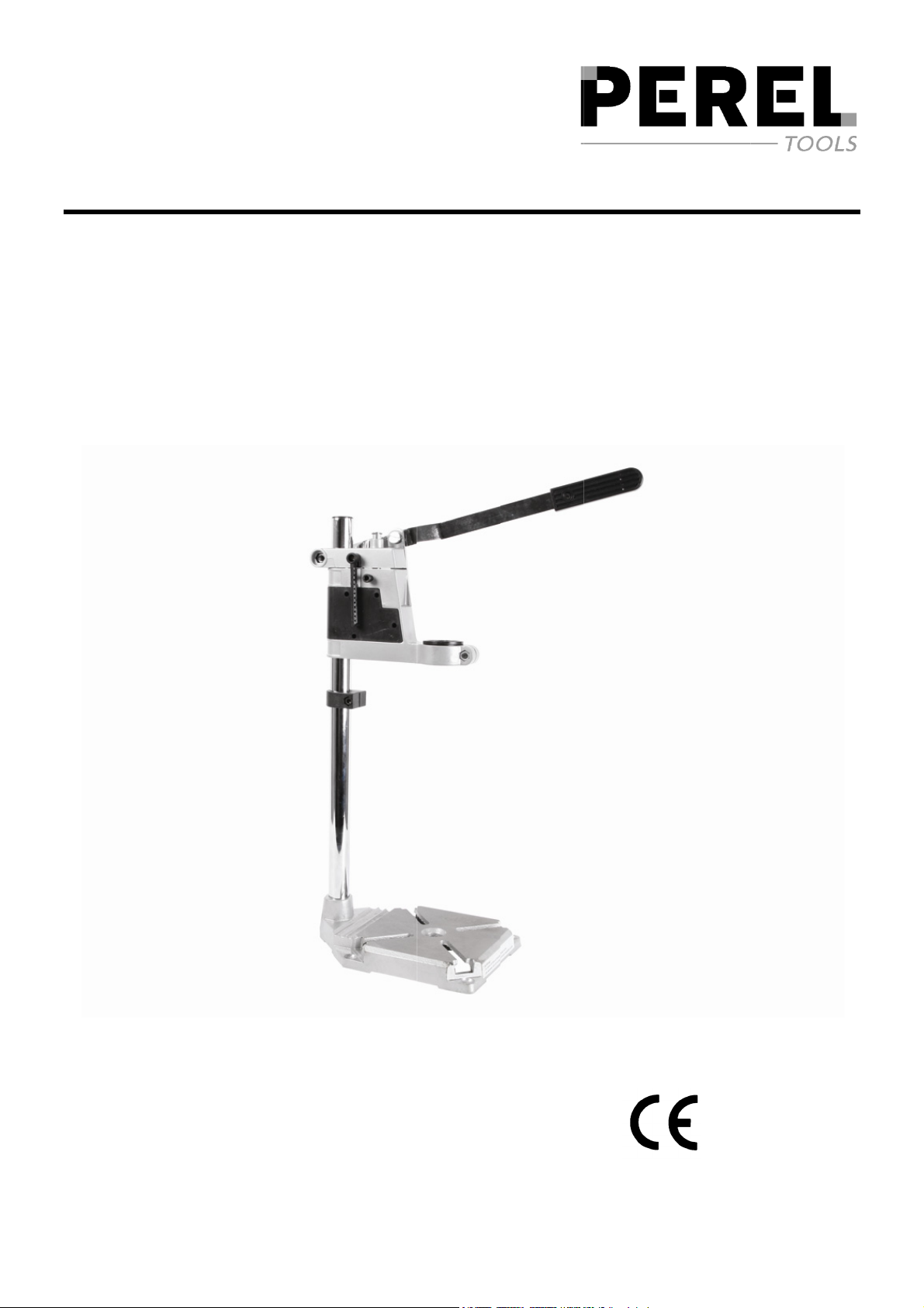
Featur
•
base with
•
for drills
•
adjustabl
5
Overvi
R
fer to the
base
column
stop
drill hol
6
Assem
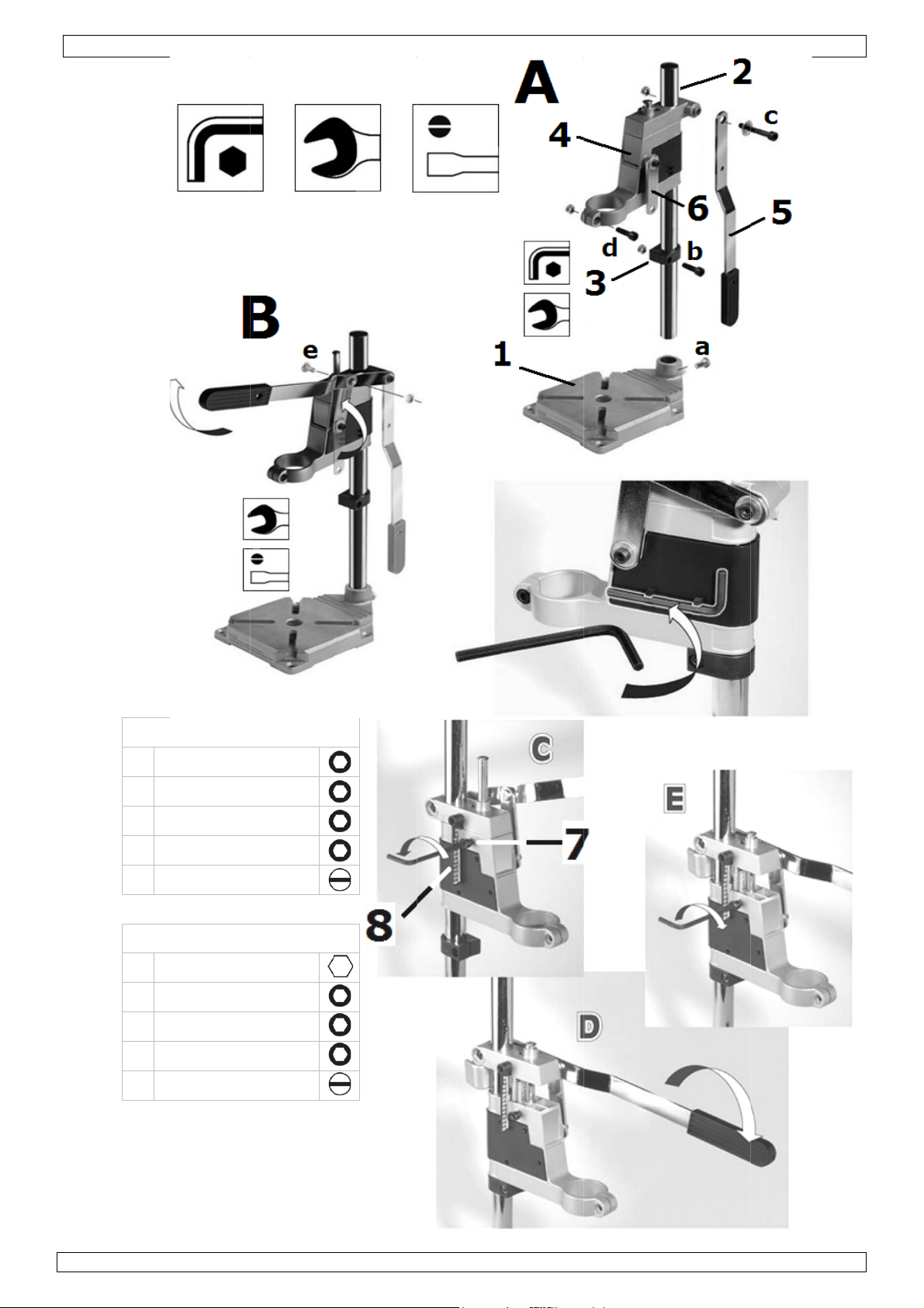
•
Insert the
•
Slide the
Slide the
•
Slide the
•
column [
Lift the le
•
Note: the
Place a w
•
The drill h
•
s
holes for s
ith 38mm
drill dept
w
llustration
er
ly
column [
top [3] o
rill holder
asher an
]. Use the
er [5] an
bolt must
sher over
older [4]
ecure ben
or 43mm
with rule
on page
] into the
er the col
[4] over t
lever [5]
included h
the lever
be inserte
the bolt [e
as a provi
h mountin
ollar
nd stop
of this m
ase [1] a
mn.
e column
over the b
ex key.
support [
at the sid
] and tigh
ion to sto
nual.
5 l
6 l
7
nd tighten
[2].
lt and us
]. Align th
e of the le
en the loc
e the hex
ever
ever supp
reset bolt
uler
it securely
this to se
holes an
er suppor
nut.
ey.
rt
with the s
ure the dr
insert th
[6].
rew(s) [a
ll holder [
bolt [e].
.
] to the
09
09/2010
3
© Velleman
nv
Page 4

WPST3 - WPST4
7. Use
• Inspect the drill stand for signs of damage before every use. When damage is noticed, do not
use it. Contact your local dealer for repair and/or spare parts.
• Keep the working area clean at all times.
• Place the drill stand on a flat and steady surface capable of carrying the weight of the stand and
the work piece. Do not use on slopes etc. …
• For security reasons, it is highly recommended to attach the drill stand to the work bench.
Screw 4 screws (not incl.) through the 4 corners of the base [1].
• Mark the location of the holes on the work piece.
• Place a drill (not incl.) with the desired drill bit (not incl.) in the drill holder [4] and tighten the
bolt [d] and nut. When necessary, use the included plastic reduction ring. Hold the drill holder
[4] with one hand to avoid that it slides down possibly causing damage to the drill bit when it
hits the base [1]. Do not switch on the drill yet.
• Pull down the lever [5] and slide down the drill holder until the tip of the drill bit almost touches
the base [1] Slide the stop [3] upwards until it touches the drill holder [4] and secure it tightly
with bolt [b]. This prevents that the drill bit accidentally hits the base during drilling.
• Place the work piece on the base [1], align the drill bit with a hole marking and secure the work
piece in such a way that it can not accidentally move during drilling (securing equipment not
included).
Note: Make sure the drill is always above the base [1] when drilling holes.
• Lower the drill holder [4] until the tip of the drill bit almost touches the work piece. Tighten the
drill holder [4] securely with bolt [c].
• Make sure all bolts are securely tightened before proceeding!
• Switch on the drill.
• When the drill is at full speed, gently pull down the lever [5]. Depending on the material of the
work piece and the diameter of the drill bit, apply some cooling liquid (not incl.) on the drill bit.
• When the desired depth is reached (see ruler
completely out of the hole. Never let go off the lever as this will cause damage to the
mechanism.
• Switch off the drill and wait until the drill bit comes to a full stop before handling the work piece.
• When multiple holes of the same depth are required, use the preset stop. Release the preset bolt
[7] on the side of the drill holder [4]. Refer to illustration [C].
• Drill the hole as described before. When the desired depth is reached, tighten the preset bolt [7].
For the following holes, simply pull down the lever [5] until it will not move any further.
[8]), gently lift the lever [5] until the drill bit is
8. Technical specifications
WPST3 WPST4
column height 400mm 510mm
column-to-drill centre 105mm
max. drill depth 60mm
weight ±1500g ±3300g
Use this device with original accessories only. Velleman nv cannot be held responsible in
the event of damage or injury resulted from (incorrect) use of this device.
For more info concerning this product, please visit our website www.perel.eu. The
information in this manual is subject to change without prior notice.
© COPYRIGHT NOTICE
This manual is copyrighted. The copyright to this manual is owned by Velleman nv. All
worldwide rights reserved. No part of this manual may be copied, reproduced, translated or reduced
to any electronic medium or otherwise without the prior written consent of the copyright holder.
09/09/2010 © Velleman® nv
4
Page 5
/
1
.
o
o
.3.
e
.
.
e1234
.
u
e
a
t
e
t
gn
v
c
c
r
d
q
v
e
s
é
e
p
u
b
g
e
e
d
e
c
é
r
e
s
é
i
h
s
c
o
e
m
g
o
c
2
3
e
e
r
d
h
a
a
e
r
g
u
u
u
i
t
ê
n
u
u
n
e
e
e
s
o
t
u
[
e
P
C
a
m
a
r
f
p
o
o
n
n
q
c
u
a
r
g
g
r
o
a
à
u
t
a
n
u
e
a
M
n
d
f
p
e
p
c
’
i
s
e
l
a
s
m6 s7 é8 g
c
[
e
a
m
o
e
t
t
u
n
a
o
s
s
é
]
c
i
v
n
o
N
t
a
a
e
e
e
e
é
c
p
t
f
p
®
t
n
é
e
Introd
N
us vous r
se
rvice de l’
nsulter vo
co
rtaines dir
ce
blèmes e
pr
2
Consi
ction
mercions
ppareil. Si
re revend
ctives de
les défaut
es de s
e votre ac
l’appareil
ur. La gar
ette notic
s qui en ré
curité
W
NOTI
at ! Lire l
été endo
ntie ne s’
et votre
sultent.
ST3 - WP
E D’E
présente
magé pe
pplique pa
evendeur
ST4
PLOI
notice atte
dant le tr
s aux dom
éclinera t
ntivement
nsport, ne
ages sur
ute respo
avant la m
pas l’insta
enus en n
sabilité po
ise en
ller et
gligeant
ur les
Directi
S
reporter à
•
Protéger
Protéger
•
Se familia
•
Toute mo
•
N’utiliser
•
La garanti
•
notice et
résultent.
La garanti
•
ni les bles
Garder ho
Toujours p
Toujours p
Toujours p
La mèche
mains nue
Ne pas util
es gén
la garant
ontre les c
ontre la c
iser avec l
ification e
u’à sa fon
e ne s’appl
otre reven
Velleman
ures corp
s de la po
orter un m
orter des
orter des l
t la perce
.
iser dans
rales
e de serv
hocs et le
aleur extr
e fonction
t interdite
tion prév
ique pas a
deur décli
®
ne couvr
relles surv
tée des en
asque de
ants de pr
nettes pr
se peuve
n environ
ce et de
raiter ave
me, la po
ement av
pour des
e. Un usa
x domma
era toute
pas les d
nus à l’us
ants et de
rotection
tection p
tectrices p
t chauffer
ement ex
ualité Vel
circonspe
ssière et l
nt l’emplo
aisons de
e impropr
es surven
esponsabi
mmages
ge de ce
s personn
endant l’u
ndant l’util
endant l’u
pendant l’
losif.
leman® e
tion pend
humidité.
.
écurité.
annule d'
us en négli
ité pour le
ux mèche
upport.
s non aut
ilisation.
isation.
ilisation.
tilisation.
fin de cet
nt l’install
ffice la ga
geant cert
problèm
, aux perc
risées.
e pas tou
e notice.
tion et l’o
rantie.
ines direc
s et les dé
uses ou la
her avec l
ération.
ives de ce
auts qui e
pièce usin
es
te
e,
4
Caract
•
base avec
•
pour perc
•
profondeu
5
Descri
S
référer a
socle
colonne
arrêt
logemen
6
Assem
•
Insérer la
Faire gliss
•
Fixer le lo
•
Placer un
•
logement
Soulever l
•
Remarqu
Placer un
•
Ranger la
•
09
09/2010
ristiqu
trous de
uses avec
r de perça
tion
x illustrati
t pour per
lage
colonne [
er l’arrêt [
ement de
rondelle
de la perc
a manette
e : Insére
rondelle s
clef Allen
s
ontage po
mandrin d
e réglable
ns en pag
euse
] dans le
] sur la c
la perceus
t la manet
use [4] s
[5] et le s
l’écrou du
ur l’écrou
ans le log
ur fixation
e 38 mm
avec grad
2 de cett
ocle [1] e
lonne [2]
e [4] sur l
e [5] sur
r la colon
upport [6]
côté du s
e] et serr
ment de l
sur établi
43 mm
ation et a
e notice.
5
fixer ave
.
colonne
l’écrou, et
e [2].
. Aligner l
pport [6].
r.
perceuse
5
rrêt
anette
upport de
crou de r
raduation
les vis [a
2].
serrer ave
s trous et
[4].
la manett
glage
.
la clef All
nsérer l’éc
n incluse
rou [e].
our fixer l
© Velleman
nv
Page 6

WPST3 - WPST4
7. Emploi
• Contrôler l’état du support avant chaque utilisation. En cas d’un endommagement visuel, ne pas
utiliser le support. Commander des pièces de rechange éventuelles chez votre revendeur.
• Garder le lieu de travail propre.
• Placer le support sur une surface plate et solide capable de supporter le poids du support, de la
perceuse et de la pièce à usiner. Ne pas utiliser le support sur une surface en pente.
• Nous vous conseillons de fixer le support à la table de travail avec 4 vis (non incluses) [1].
• Placer la perceuse dans le logement [4] et serrer l’écrou [d]. Si nécessaire, utiliser la rondelle en
plastique. Maintenir le logement [4] avec une main afin d’éviter qu’il ne glisse. Ne pas encore
allumer la perceuse.
• Tirer la manette [5] vers vous jusqu’à ce que la mèche de la perceuse se trouve à fleur du socle
[1]. Faire glisser l’arrêt [3] jusqu’à ce qu’il touche le logement de la perceuse [4]. Serrer l’écrou
de l’arrêt [b]. L’arrêt prévient que la mèche ne touche le socle pendant l’utilisation.
• Placer la pièce à usiner sur le socle [1], l’aligner et la fixer (accessoires de fixation non inclus).
Remarque : Tourner le logement [4] de manière à ce que la mèche soit toujours positionnée audessus du socle [1].
• Tirer la manette [5] vers vous jusqu’à ce que la mèche de la perceuse se trouve à fleur de la
pièce à usiner sans la toucher. Serrer l’écrou [c] du logement [4].
• S’assurer que tous les écrous soient serrés avant de procéder !
• Allumer la perceuse.
• Attendre que la mèche tourne à plein régime et tirer doucement la manette [5] vers vous.
Appliquer un liquide refroidissant (non inclus) si nécessaire.
• Une fois la profondeur de perçage atteinte (voir la graduation [8]), relever doucement la manette
[5] et s’assurer que la mèche soit entièrement libre. Ne jamais relâcher brusquement la manette
afin d’éviter d’endommager le mécanisme.
• Éteindre la perceuse et attendre que la mèche ne tourne plus avant de manier la pièce usinée.
Utiliser l’arrêt préréglé pour des perçages en série. Desserrer l’écrou de réglage [7] sur le côté du
•
logement [4] (voir l’illustration [C]).
Percer le trou comme décrit ci-dessus. Une fois la profondeur de perçage atteinte, serrer l’écrou
de réglage [7]. En abaissant la manette [5] la perceuse s’arrête automatiquement à la
profondeur réglée.
8. Spécifications techniques
WPST3 WPST4
hauteur de la colonne 400 mm 510 mm
écartement colonne-mèche 105 mm
profondeur de perçage max. 60 mm
poids ±1500 g ±3300 g
N’employer cet appareil qu’avec des accessoires d’origine. SA Velleman ne sera
aucunement responsable de dommages ou lésions survenus à un usage (incorrect) de cet
appareil. Pour plus d’information concernant cet article, visiter notre site web
www.perel.eu. Toutes les informations présentées dans cette notice peuvent être
modifiées sans notification préalable.
© DROITS D’AUTEUR
SA Velleman est l’ayant droit des droits d’auteur pour cette notice.
Tous droits mondiaux réservés. Toute reproduction, traduction, copie ou diffusion, intégrale ou
partielle, du contenu de cette notice par quelque procédé ou sur tout support électronique que se
soit est interdite sans l’accord préalable écrit de l’ayant droit.
09/09/2010 © Velleman® nv
6
Page 7

/
1
.
ahegadeve
.3.
a
.
.
a1234
.
n
e
d
e
e
e
e
h
e
o
a
a
c
m
r
e
o
b
b
k
r
e
a
n
n
o
t
o
r
e
e
e
e
n
e
t
n
o
r
s
e
e
g
m
a
e
g
n
i
]
2
d
e
B
z
n
b
b
b
s
e
e
e
e
g
v
e
b
a
g
d
t
d
n
P
E
d
e
v
n
v
i
t
t
n
i
m
d
v
j
v
a
N
h
e
e
e
e
e
e
e
n
j
h
B
o
a
s
e
h6 h7 a8 s
r
n
u
m
I
e
e
c
r
e
r
e
e
a
n
e
v
e
n
e
n
h
a
n
e
e
c
s
n
a
l
n
v
n
n
m
®
r
u
t
d
r
Inleidi
D
nk u voor
t toestel b
rantie gel
aler zal de
rband me
2
Veiligh
uw aanko
schadigd
t niet voor
verantwo
houden.
idsinst
GE
p! Lees de
ijdens het
schade do
rdelijkheid
ucties
W
RUIK
e handlei
transport,
or het neg
afwijzen
ST3 - WP
RSHA
ing grondi
installeer
ren van b
oor defect
ST4
DLEID
g voor u h
et dan nie
paalde ric
n of probl
NG
t toestel i
t en raadpl
htlijnen in
men die
gebruik
eeg uw de
deze hand
ier rechtst
eemt. We
ler. De
eiding en
reeks
d
w
Algem
R
adpleeg d
•
Bescherm
•
Bescherm
•
Leer eerst
•
Om veilig
Gebruik h
•
garantie.
Schade d
•
Schade a
•
garantie v
Houd uit d
Draag tijd
Draag tijd
Draag tijd
De boor e
blote hand
Vermijd g
ne rich
Vellema
tegen sch
tegen ext
de functie
eidsreden
t toestel
or wijzigin
n de boor
n Vellema
buurt va
ns het ge
ns het ge
ns het ge
het werk
en aanrak
bruik in e
lijnen
®
service
kken en v
eme temp
van het t
n mag u
nkel waar
en die de
achine, d
n®.
kinderen
ruik altijd
ruik altijd
ruik altijd
tuk kunne
n.
n explosie
- en kwal
rmijd bru
raturen, s
oestel ken
een wijzig
oor het ge
gebruiker
boor, het
en onbevo
een besch
bescherm
een besch
tijdens h
e atmosfe
teitsgara
e kracht ti
of en voc
en voor u
ngen aanb
maakt is.
heeft aang
werkstuk
gden.
rmend ma
nde hands
rmende b
t gebruik
er.
tie achte
dens de b
tigheid.
het gaat g
rengen.
ij onoord
ebracht va
f elke lich
sker.
hoenen.
il.
xtreem w
aan de ha
diening.
ebruiken.
elkundig g
lt niet ond
melijke s
rm worde
dleiding.
bruik ver
r de gara
hade valt
. Niet me
alt de
tie.
iet onder
e
4
Eigens
•
basis met
•
voor boor
•
instelbare
5
Omsch
R
adpleeg d
basis
kolom
dieptest
houder
6
Assem
•
Steek de
Schuif de
•
Schuif de
•
Plaats de
•
[4] aan d
Hef het h
•
Opmerki
Plaats ee
•
U kunt de
•
09
09/2010
happen
montageg
achine m
boordiept
ijving
afbeeldin
p
oormachi
lage
olom [2]
dieptestop
houder [4
ing en het
kolom [
ndvat [5]
g: Steek
ring over
inbussleut
ten voor
et boorkop
met scha
en op pa
e
n de basis
[3] over
over de k
handvat [
] te beves
en de hou
e bout lan
de bout [e
l opberge
evestiging
van 38 m
lverdeling
ina 2 van
[1] en be
e kolom.
olom [2].
5] over de
igen.
er [6]. Li
gs de kant
] en draai
in de da
op werkb
tot 43 m
en diepte
eze handl
5
estig met
bout en d
n de gate
van de ho
ast.
rtoe beste
7
nk
m
top
iding.
andvat
ouder ha
fstelbout
chaalverd
de schroe
aai vast m
uit en ste
der [6] i
de ruimt
dvat
ling
en [a].
et de inbu
k de bout
het gat.
in de hou
sleutel o
[e] in het
der [4].
de houde
gat.
© Velleman
nv
Page 8

WPST3 - WPST4
7. Gebruik
• Controleer de staat van de standaard vóór elk gebruik. Gebruik de standaard niet in geval van
zichtbare schade. Bestel eventuele reserveonderdelen bij uw dealer.
• Houd de werkplaats altijd netjes.
• Plaats de standaard op een egaal en stevig oppervlak dat het gewicht van de standaard, de
boormachine en het werkstuk kan dragen. Gebruik de standaard nooit op een hellend vlak.
• Het is aan te raden om de standaard aan de werkbank te bevestigen. Doe dit met 4 schroeven
(niet meegeleverd) [1].
• Plaats de boormachine in de houder [4] en draai de bout [d] vast. Gebruik de plastic ring indien
nodig. Houd de houder [4] met één hand vast zodat hij niet glijdt. Schakel de boormachine nog
niet in.
• Trek het handvat [5] naar u toe tot de boor op gelijke hoogte van de basis [1] komt te staan.
Schuif de dieptestop [3] tegen de houder [4] en bevestig met de bout [b]. De dieptestop
voorkomt dat de boor bij het gebruik de basis raakt.
• Plaats het werkstuk op de basis [1], lijn uit en bevestig (bevestigingsaccessoires niet
meegeleverd).
Opmerking: Draai de houder [4] zodanig dat de boor altijd bovenop de basis [1] komt te staan.
• Trek het handvat [5] naar u toe tot de boor op gelijke hoogte van het werkstuk komt te staan.
Draai de bout [c] van de houder [4] stevig vast.
• Zorg dat alle bouten stevig vastgedraaid zijn alvorens verder te gaan!
• Schakel de boormachine in.
• Wacht tot de boor op volle toeren draait en trek het handvat [5] zachtjes naar u toe. Gebruik
eventueel een beetje koelvloeistof (niet meegeleverd).
• Eens de boor op de gewenste diepte (zie schaalverdeling [8]), laat het handvat [5] voorzichtig
los tot de boor volledig uit het werkstuk verwijderd is. Laat het handvat nooit bruusk los om het
mechanisme niet te beschadigen.
• Schakel de boormachine uit en wacht tot de boor niet meer draait alvorens het werkstuk te
behandelen.
• Gebruik de vooringestelde dieptestop voor serieboringen. Draai de afstelbout [7] op de zijkant
van de houder [4] los (zie afbeelding [C]).
• Boor het gat zoals hierboven beschreven. Eens de boor op de gewenste diepte, draai de
afstelbout [7] vast. Als u nu het handvat [5] naar u toe trekt, zal de boormachine automatisch
op de ingestelde hoogte stoppen.
8. Technische specificaties
WPST3 WPST4
kolomhoogte 400 mm 510 mm
afstand kolom-boor 105 mm
max. boordiepte 60 mm
gewicht ±1500 g ±3300 g
Gebruik dit toestel enkel met originele accessoires. Velleman nv is niet aansprakelijk voor
schade of kwetsuren bij (verkeerd) gebruik van dit toestel. Voor meer informatie over dit
product, zie www.perel.eu. De informatie in deze handleiding kan te allen tijde worden
gewijzigd zonder voorafgaande kennisgeving.
© AUTEURSRECHT
Velleman nv heeft het auteursrecht voor deze handleiding.
Alle wereldwijde rechten voorbehouden. Het is niet toegestaan om deze handleiding of gedeelten
ervan over te nemen, te kopiëren, te vertalen, te bewerken en op te slaan op een elektronisch
medium zonder voorafgaande schriftelijke toestemming van de rechthebbende.
09/09/2010 © Velleman® nv
8
Page 9

/
1
.
n
o
.3.
é
.
.
é1234
.
u
e
c
s
e
g
e
e
o
a
t
e
a
a
p
u
d
je
a
a
a
c
a
p
u
n
d
e
e
a
s
E
a
f
r
o
e
e
a
p
d
n
o
l
y
5
d
e
M
W
s
a
e
d
e
c
e
o
e
m
a
c
p
8
e
a
[
a
a
o
r
o
P
L
P
a
t
e
c
ó
e
u
p
n
s
o
r
m
e
]
A
p
a
U
a
e
o
n
b
j
s
a
n
u
o
a
d
r
u
p6 s7 t8 e
o
g
o
t
r
o
o
e
e
e
e
a
e
a
a
s
n
u
s
c
a
e
t
u
s
e
e
e
ñ
s
b
c
r
u
c
®
a
e
a
Introd
¡G
racias por
tes de usa
a
co
ntacto con
es
te manual
blemas r
pr
2
Instru
cción
haber com
rlo. Si el a
su distrib
invalidará
sultantes.
ciones
prado el
arato ha
idor. Los d
su garant
e segur
W
ANUA
PST3/W
ufrido algú
años caus
ía y su dis
idad
ST3 - WP
DEL
ST4! Lea
n daño en
dos por d
ribuidor n
ST4
SUARI
tentamen
el transpo
scuido de
será resp
O
e las instr
te no lo in
las instruc
nsable de
cciones d
tale y pón
iones de s
ningún da
l manual
gase en
eguridad d
o u otros
e
Norma
V
ase la Gar
•
No agite
No expon
•
Familiaríc
•
Por razon
•
Utilice sól
•
garantía c
Los daños
•
La garantí
•
uso de es
Mantenga
Lleve siem
Lleve siem
Lleve siem
La broca y
desnudas.
No utilice
gener
antía de
l aparato.
a este ap
se con el
s de segu
el aparat
ompletam
causados
Velleman
e soporte.
l aparato
pre una m
pre guant
pre gafas
el taladro
l aparato
les
ervicio y
vite usar
rato a cal
uncionami
idad, las
para las
nte.
por modifi
®
no cubra
lejos del al
scarilla d
s de prote
e protecci
pueden cal
n un ambi
alidad V
xcesiva f
r extremo,
nto del a
odificacio
plicacione
aciones n
daños a b
cance de p
protecció
ción si tra
n si traba
entarse du
ente explo
lleman®
erza dura
polvo y h
arato ante
es no aut
descritas
autorizad
ocas, tala
ersonas n
si trabaja
ajas con
as con est
rante el us
ivo.
l final de
te el man
medad.
s de utiliza
rizadas de
en este m
s, no está
ros y la pi
capacitad
s con este
ste aparat
aparato.
o. No tóqu
ste manua
jo y la ins
rlo.
l aparato e
nual. Su
n cubierto
za, ni las l
s y niños.
aparato.
o.
los con la
l del usuar
alación.
stán prohi
so incorre
por la ga
siones ca
manos
io.
idas.
to anula l
antía.
sados por
l
4
Caract
•
base con
•
para talad
•
profundid
5
Descri
V
ase las fig
base
columna
tope de
soporte
6
Monta
•
Introduzc
Deslice el
•
Fije el sop
•
Ponga un
•
el soporte
Levante l
•
Observa
Ponga un
•
Guarde la
•
rísticas
gujeros d
ros con m
d de talad
ción
ras en la
profundida
e taladro
la colum
tope de pr
orte del ta
arandela
de taladro
palanca [
ión: Intro
arandela
llave Allen
montaje
ndril de 3
ro ajustabl
ágina 2 d
a [2] en l
fundidad
adro [4]
la palanc
[4] a la c
] y el sop
uzca el to
n el tornil
en el sop
ara fijació
mm a 43
e con grad
este man
base [1]
3] sobre l
la column
[5] sobr
lumna [2
orte [6].
nillo del la
lo [e] y a
rte del tal
n a un ban
m
ación y pa
ual del us
5
y fije con l
a columna
a [2].
el tornill
.
linee los a
do del sop
riete.
dro [4].
co de trab
ada
ario.
alanca
oporte de
ornillo de
scala
os tornillo
[2].
, y apriete
ujeros e i
rte [6].
jo
la palanca
juste
[a].
con la llav
troduzca
e Allen (in
l tornillo [
l.) para fij
e].
r
09
09/2010
9
© Velleman
nv
Page 10

WPST3 - WPST4
7. Uso
• Controle el estado del soporte antes de cada uso. En caso de daños visuales, no utilice el soporte.
Contacte con su distribuidor si necesita piezas de recambio.
• Mantenga el lugar de trabajo siempre ordenado.
• Ponga el soporte en una superficie plana y sólida capaz de soportar el peso del soporte, el taladro
y la pieza que quiere trabajar. No utilice el aparato en una superficie en pendiente.
• Fije el soporte a la mesa de trabajo con 4 tornillos (no incl.) [1].
• Ponga el taladro en el soporte [4] y apriete el tornillo [d]. Si fuera necesario, utilice la arandela
de plástico. Mantenga el soporte [4] con una mano para evitar que deslice. Todavía no active el
taladro.
• Tire de la palanca [5] hacia usted hasta que la broca del taladro esté en la misma altura de la
base [1]. Deslice el tope de profundidad [3] hasta que toque el soporte del taladro [4]. Apriete
el tornillo del tope de profundidad [b]. El tope de profundidad impide que la broca toque la base
durante el uso.
• Ponga la pieza que quiere trabajar en la base [1], alinéela y fíjela (accesorios de fijación no
incl.).
Observación: Gire el soporte [4] de manera que la broca siempre está posicionada encima de la
base [1].
• Tire de la palanca [5] hacia usted hasta que la broca del taladro esté en la altura de la pieza que
quiere trabajar sin tocarla. Apriete el tornillo [c] del soporte [4].
• ¡Asegúrese de que todos los tornillos estén apretados antes de continuar!
• Active el taladro.
• Espere hasta que la broca gire a velocidad máxima y tire cuidadosamente de la palanca [5] hacia
usted. Aplique un líquido refrigerante (no incl.) si fuera necesario.
• Después de haber alcanzado la profundidad de taladro (véase la escala [8]), levante
cuidadosamente la palanca [5] y asegúrese de que la broca esté completamente libre. Nunca
suelte la palanca de manera brusca para no dañar el mecanismo.
• Desactive el taladro y espere hasta que la broca ya no gire antes de manejar la pieza.
• Utilice el tope de profundidad preajustado para taladros en serie. Desatornille el tornillo [7] del
lado del soporte [4] (véase fig. [C]).
Taladre el agujero como está descrito arriba. Después de haber alcanzado la profundidad de
taladro, apriete el tornillo de ajuste [7]. Al bajar la palanca [5] el taladro se para
automáticamente a la profundidad regulada.
8. Especificaciones
WPST3 WPST4
altura de la columna 400 mm 510 mm
distancia columna/broca 105 mm
profundidad de taladro máx. 60 mm
peso ±1500 g ±3300 g
Utilice este aparato sólo con los accesorios originales. Velleman NV no será responsable
de daños ni lesiones causados por un uso (indebido) de este aparato. Para más
información sobre este producto, visite nuestra página web www.perel.eu. Se pueden
modificar las especificaciones y el contenido de este manual sin previo aviso.
© DERECHOS DE AUTOR
Velleman NV dispone de los derechos de autor para este manual del usuario.
Todos los derechos mundiales reservados. Está estrictamente prohibido reproducir, traducir, copiar,
editar y guardar este manual del usuario o partes de ello sin previo permiso escrito del derecho
habiente.
09/09/2010 © Velleman® nv
10
Page 11

/
1
.
i
cda
.3.
e
.
.
e1234
.
r
n
d
t
h
e
m
n
e
S
S
h
n
e
®
k
c
M
r
r
u
s
g
S
S
r
]
e
t
s
d
w
e
e
e
S
h
i
r
ä
n
G
n
c
m
V
c
t
t
n
e
h
n
e
c
e
B
Ü
n
d
d
d
d
n
Q
V
r
B
ü
u
e
n
e
f
e
S
e
s
n
B
P
U
/
n
r
m
e
d
d
d
c
i
n
a
p
c
u
u
t
a
S
[
r
4
e
c
t
d
L
a
c
e
ä
w
p
m
e
s
r
c
u
e
e
m
H6 H7 S8 S
d
n
5
e
t
c
e
G
i
n
c
e
k
u
e
m
s
i
r
n
c
B
r
e
n
S
d
n
e
B
r
u
u
a
c
r
S
n
]
a
n
t
e
r
a
o
S
e
®
F
h
s
m
Einfüh
W
r bedanke
In
betriebnah
se
in, verwen
htbeachtu
Ni
raus resul
2
Sicher
ung
uns für d
me sorgfäl
en Sie da
ng der Be
ierende Fo
eitshin
n Kauf de
ig durch.
Gerät nic
ienungsan
lgeschäde
eise
W
EDIEN
s WPST3
berprüfen
ht und we
leitung ve
übernim
ST3 - WP
NGSAN
WPST4!
Sie, ob Tr
den Sie si
ursacht w
t der Hers
ST4
LEITUN
esen Sie d
nsportsch
h an Ihre
rden, erlis
teller kein
ese Bedie
äden vorli
Händler.
ht der Ga
Haftung
ungsanlei
gen. Sollt
ei Schäde
antieansp
ung vor
dies der
n, die durc
uch. Für
all
h
Allgem
Si
he Velle
•
Vermeide
des Gerät
Schützen
•
Nehmen
•
haben.
Eigenmäc
•
Verwende
•
kann dies
Bei Schäd
•
Velleman
•
Werkstüc
Halten Sie
Tragen Si
Tragen Si
Tragen Si
Die Bohrm
Berühren
Vermeiden
ine Ric
an® Serv
Sie Erschü
s.
ie das Ge
ie das Ger
tige Verä
Sie das
zu Schäde
n verursa
übernim
noch für
Kinder un
während
während
während
aschine un
ie diese al
Sie die A
tlinien
ce- und
tterungen.
ät vor ext
t erst in
derungen
erät nur f
am Prod
ht durch
t weder ei
erletzung
Unbefugt
er Anwen
er Anwen
er Anwen
d Werkstü
so nicht m
wendung i
ualitätsg
ermeiden
emen Tem
etrieb, na
sind aus Si
r Anwend
kt führen
igenmäch
e Haftung
n.
vom Ger
ung imme
ung imme
ung imme
k können
t bloßen H
einer ex
rantie a
Sie rohe G
eraturen,
hdem Sie
cherheitsg
ngen bes
nd erlisch
ige Änder
für Schäd
t fern.
r eine Mas
r Schutzha
r eine Sch
ährend d
änden.
losiven At
Ende die
walt währe
Staub und
ich mit se
ünden ve
hrieben in
t der Gara
ngen erlis
n an der
e.
ndschuhe.
tzbrille.
r Anwend
osphäre.
er Bedien
nd der Inst
Feuchte.
nen Funkti
boten.
dieser Bed
tieanspru
ht der Ga
ohrmaschi
ng sehr w
ngsanleitu
llation und
onen vertr
ienungsanl
h.
antieanspr
ne, dem B
arm werde
ng.
Bedienung
ut gemac
eitung son
uch.
hrer, dem
n.
t
t
4
Eigens
•
Basis mit
•
für Bohrm
•
einstellba
5
Umsch
Si
he Abbild
Basis
Ständer
Tiefenan
Bohrma
6
Monta
•
Stecken S
•
Schieben
Schieben
•
Positionie
•
Sechskant
Heben Sie
•
Bolzen [e
Bemerku
09
09/2010
haften
ontagelö
aschine mi
e Bohrung
eibung
ngen, Sei
schlag
chinenhal
e
ie den Stä
ie den Ti
ie den Bo
en Sie de
schlüssel f
den Hebel
in das Lo
ng: Steck
her für Be
t Bohrfutt
stiefe mit
e 2 dieser
er
der [2] in
fenanschla
rmaschin
Dichtung
st, um de
[5] und d
h.
n Sie den
estigung
r von 38m
kala und
Bedienung
die Basis
g [3] übe
nhalter [
ring und d
Bohrmas
en Hebelal
olzen an
n einer W
m bis 43m
topp
sanleitung
5
1] und be
den Stän
] über de
n Hebel [
hinenhalt
er [6]. Ri
er Seite d
11
rkbank
.
ebel
ebelhalte
tellschrau
kala
festigen Si
er.
Ständer [
] über de
r [4] am
hten Sie
s Hebelha
be
mit den
2].
Bolzen u
tänder [2
ie Löcher
lters [6] i
chrauben
d drehen
zu befest
us und st
das Loch.
[a].
ie mit de
igen.
cken Sie d
© Velleman
en
nv
Page 12

WPST3 - WPST4
• Positionieren Sie den Ring über den Bolzen [e] und drehen Sie fest.
• Sie können den Sechskantschlüssel in den dafür vorgesehenen Raum im Bohrmaschinenhalter
[4] lagern.
7. Anwendung
• Überprüfen Sie den Zustand des Gerätes vor jedem Gebrauch. Verwenden Sie das Gerät nicht
beim sichtbaren Schaden. Bestellen Sie eventuelle Ersatzteile bei Ihrem Fachhändler.
• Halten Sie die Werkstatt immer sauber.
• Positionieren Sie das Gerät auf einem glatten und flachen Untergrund, die das Gewicht des
Halters, der Bohrmaschine und des Werkstückes tragen kann. Verwenden Sie das Gerät nie auf
einer schieben Ebene.
• Befestigen Sie das Gerät an der Werkbank. Verwenden Sie 4 Schrauben (nicht mitgeliefert) [1].
• Stellen Sie die Bohrmaschine in den Bohrmaschinenhalter [4] und drehen Sie den Bolzen [d]
fest. Verwenden Sie den Plastikring wenn nötig. Halten Sie den Bohrmaschinenhalter [4] mit
einer Hand fest damit er nicht wegrutscht. Schalten Sie die Bohrmaschine noch nicht ein.
• Ziehen Sie den Hebel [5] zu sich hinüber bis der Bohrer sich auf gleicher Höhe der Basis [1]
befindet. Schieben Sie den Tiefenanschlag [3] gegen den Bohrmaschinenhalter [4] und
befestigen Sie mit dem Bolzen [b]. Der Tiefenanschlag verhindert, dass der Bohrer während der
Anwendung die Basis berührt.
• Positionieren Sie das Werkstück auf der Basis [1], richten Sie aus und befestigen Sie
(Befestigungszubehör nicht mitgeliefert).
Bemerkung: Drehen Sie den Bohrmaschinenhalter [4] so, dass der Bohrer sich immer obenauf
der Basis [1] befindet.
• Ziehen Sie den Hebel [5] zu sich hinüber bis der Bohrer sich auf gleicher Höhe des Werkstücks
befindet. Drehen Sie den Bolzen [c] des Bohrmaschinenhalters [4] gut fest.
• Beachten Sie, dass alle Bolzen gut festgedreht sind, ehe Sie anfangen!
• Schalten Sie die Bohrmaschine ein.
• Warten Sie bis die Bohrmaschine auf Höchstgeschwindigkeit dreht und ziehen Sie den Hebel
vorsichtig zu sich hinüber. Verwenden Sie eventuell ein bisschen Kühlflüssigkeit (nicht mitgeliefert).
• Befindet sich der Bohrer auf gewünschter Tiefe (siehe Skala [8]), so lassen Sie den Hebel [5]
vorsichtig los bis der Bohrer völlig aus dem Werkstück entfernt ist. Lassen Sie den Hebel nie brüsk
los, um das Mechanismus nicht zu beschädigen.
• Schalten Sie die Bohrmaschine ab und warten Sie bis diese nicht mehr funktioniert, ehe Sie das
Werkstück behandeln.
• Verwenden Sie den voreingestellten Tiefenanschlag für Serienbohrungen. Drehen Sie die
Stellschraube [7] auf der Seite des Bohrmaschinenhalters [4] los (siehe Abb. [C]).
• Bohren Sie das Loch wie oben beschrieben. Befindet sich der Bohrer auf gewünschter Tiefe, so
drehen Sie die Stellschraube [7] fest. Ziehen Sie nun den Hebel [5] zu sich hinüber, so stoppt die
Bohrmaschine automatisch auf der eingestellten Höhe.
[5]
8. Technische Daten
WPST3 WPST4
Ständerhöhe 400 mm 510 mm
Abstand Ständer/Bohrer 105 mm
max. Bohrungstiefe 60 mm
Gewicht ±1500 g ±3300 g
Verwenden Sie dieses Gerät nur mit originellen Zubehörteilen. Velleman NV übernimmt
keine Haftung für Schaden oder Verletzungen bei (falscher) Anwendung dieses Gerätes.
Für mehr Informationen zu diesem Produkt, siehe www.perel.eu. Alle Änderungen ohne
vorherige Ankündigung vorbehalten.
© URHEBERRECHT
Velleman NV besitzt das Urheberrecht für diese Bedienungsanleitung.
Alle weltweiten Rechte vorbehalten. Ohne vorherige schriftliche Genehmigung des Urhebers ist es
nicht gestattet, diese Bedienungsanleitung ganz oder in Teilen zu reproduzieren, zu kopieren, zu
übersetzen, zu bearbeiten oder zu speichern.
09/09/2010 © Velleman® nv
12
Page 13

/
.
bo u
u
.3.
e
.
.
e1234
.
u
r
m
n
s
s
n
e
n
e
s
a
c
e
e
a
ç
a
o
d
g
z
p
p
ç
c
r
o
t
s
gu
o
o
z
r
e
a
e
m
p
®
z
m
a
n
n
u
2
a
r
e
[
n
n
N
r
O
a
e
m
z
l
a
a
o
m
a
e
a
u
e
e
o
4
c
]
p
f
o
t
W
P
D
g
t
c
o
m
e
p
q
e
a
ã
r
A
e
e
n
o
e
a
a
h
r
p
n
r
e
m
s
o
a6 s7 p8 e
n
s
r
r
D
a
i
o
p
a
n
e
a
o
m
e
]
e
e
o
o
a
o
t
o
ç
a
a
u
e
o
a
e
ç
a
e
®
r
õ
a
ST3 - WP
ST4
1
Introd
O
rigada po
sar. Caso
co
ntacto co
gurança re
se
alquer da
q
2
Norma
ter adqui
o aparelh
o seu dis
feridas ne
o ou outro
de se
Mantenha
Use sempr
Use sempr
Use sempr
A broca e
mãos desp
Nunca utili
ão
MA
ido o WPS
tenha sof
ribuidor.
te manual
s problem
rança
aparelho
e máscara
e luvas de
e óculos d
berbequi
rotegidas.
e o apare
UAL
T3/WPST
ido algum
s danos ca
anulam a
s resultan
fora do al
de protecç
protecção
protecçã
podem a
ho num a
O UT
4! Leia ate
dano dura
usados pel
arantia e
es.
ance de p
ão ao trab
ao trabalh
ao trabal
quecer du
biente ex
ILIZA
ntamente
te o trans
o não cum
seu distr
ssoas não
lhar com
r com o a
ar com o
ante a utili
losivo.
OR
s instruçõ
porte não
primento d
buidor nã
capacitad
aparelho.
arelho.
parelho.
zação. Nã
s do man
instale e
as normas
será resp
s e crianç
lhes toqu
al antes d
ntre em
de
nsável po
s.
com as
e
Norma
V
ja a Gara
•
Não aban
Não expo
•
Familiariz
•
Por razõe
•
Utilize o a
•
anula a g
Os danos
•
A garantia
•
provocada
4
Caract
•
base com
•
para berb
•
profundid
5
Descri
V
ja as figur
base
coluna
regulad
suporte
gerais
tia de se
o aparelh
ha o apar
-se com o
de segur
parelho ap
rantia co
ausados
Velleman
s pela utili
rísticas
furação pa
quins co
de de fur
ão
s da pági
r de profu
e berbeq
viço e qu
o. Evite us
lho ao cal
funciona
nça, estão
nas para
pletament
or modific
não cobre
ação do s
ra montag
mandril d
nção regul
a 2 deste
didade
im
lidade V
r força ex
r extremo
ento do a
proíbidas
s aplicaçõ
.
ções não
danos nas
porte.
m e fixaç
38mm a
ável
manual do
lleman®
cessiva du
, pó e hum
arelho ant
uaisquer
s descrita
utorizada
brocas, n
o a uma b
43mm
utilizador.
5
a parte fi
ante o ma
idade.
s de o util
odificaçõ
s neste m
, não estã
berbequi
ancada de
lavanca
uporte da
arafuso d
scala
al deste m
nuseamen
izar.
s não aut
nual. Uma
cobertos
ou na pe
trabalho.
alavanca
ajuste
anual do u
o e utiliza
rizadas.
utilização
pela garan
a, nem qu
tilizador.
ão.
incorrecta
tia.
isquer les
es
6
Monta
•
Introduza
Faça desli
•
Fixe o su
•
Coloque u
•
fixar o su
Levante a
•
Observa
Coloque u
•
Guarde a
•
09
09/2010
em
a coluna [
ar o regul
orte do be
ma anilha
orte [4] à
alavanca
ão: Introd
ma anilha
have Alle
] na base
dor de pr
bequim [
a alavan
coluna [2
5] e o su
uza o para
o parafus
no supor
[1] e fixe
fundidade
] à coluna
a [5] sob
.
orte [6].
uso do lad
[e] e ap
e de berb
com os pa
[3] ao lo
[2].
e o parafu
linhe a fu
o do supo
rte.
quim [4].
13
rafusos [a
go da colu
o, e apert
ação e intr
te [6].
.
na [2].
com um
oduza o p
chave All
rafuso [e]
n (incl.) p
.
© Velleman
ra
nv
Page 14

WPST3 - WPST4
7. Utilização
• Verifique o estado do suporte antes de cada utilização. Em caso de danos visíveis, não utilize o
suporte. Contacte o seu distribuidor caso necessite de peças de substituição.
• Mantenha o local de trabalho devidamente arrumado.
• Coloque o suporte numa superficie plana e sólida capaz de suportar o peso do suporte, o
berbequim e a peça na qual vai trabalhar. Não utilize o aparelho numa superfície instável.
• Fixe o suporte à mesa de trabalho utilizando 4 parafusos (não incl.) [1].
• Coloque o berbequim no suporte [4] e aperte o parafuso [d]. Caso seja necessário, utilize a
anilha de plástico. Segure o suporte [4] com uma das mãos para evitar que deslize. Não ligue o
berbequim.
• Puxe a alavanca [5] na sua direcção até que a broca do berbequim esteja à mesma altura da
base [1]. Faça deslizar o regulador de profundidade [3] até tocar no suporte [4]. Aperte o
parafuso do regulador de profundidade [b]. O regulador de profundidade impede que a broca
toque na base durante a utilização.
• Coloque a peça que pretende trabalhar na base [1], alinhe-a e fixe-a (acessórios de fixação não
incl.).
Observação: Gire o soporte [4] de forma a que a broca esteja sempre posicionada por cima da
base [1].
• Puxe a alavanca [5] na sua direcção até que a broca esteja à da peça que pretende trabalhar
sem lhe tocar. Aperte o parafuso [c] do suporte [4].
• Verifique se todos os parafusos estão bem apertados antes de continuar!
• Ligue o berbequim.
• Espere até que a broca gire à velocidade máxima e puxe cuidadosamente a alavanca [5] na sua
direcção. Aplique um líquido refrigerante (não incl.) se for necessário.
• Após ter regulado a profundiade pretendida para o berbequim (veja a escala [8]), levante
cuidadosamente a alavanca [5] e verifique se a broca está completamente livre. Nunca solte a
alavanca de forma brusca para não danificar o mecanismo.
Desligue o berbequim e espere até que a broca já não gire até mexer na peça.
•
• Utilize a regulação de profundidade prédefinida para berbequins em série. Desaperte o parafuso
[7] no lado do suporte [4] (veja fig. [C]).
Faça o furo conforme descrito acima. Após ter alcançado a profundidade do berbequim, aperte o
parafuso de ajuste [7]. Ao baixar a alavanca [5] o berbequim fica automáticamente na
profundidade regulada.
8. Especificações
WPST3 WPST4
altura da coluna 400 mm 510 mm
distância coluna/broca 105 mm
profundidade máx.do berbequi 60 mm
peso ±1500 g ±3300 g
Utilize este aparelho apenas com acessórios originais. A Velleman NV não será
responsável por quaisquer danos ou lesões causados pelo uso (indevido) do aparelho.
Para mais informação acerca deste produto, visite a nossa página web www.perel.eu.
Podem alterar-se as especificações e o conteúdo deste manual sem aviso prévio.
© DEREITOS DE AUTOR
A Velleman NV detem os direitos de autor sobre este manual do utilizador.
Todos os direitos mundiais reservados. É estrictamente proíbido reproduzir, traduzir, copiar, editar e
gravar este manual do utilizador ou partes do mesmo sem prévia autorização escrita por parte da
detentora dos direitos.
09/09/2010 © Velleman® nv
14
Page 15

Velleman® Service and Quality Warranty
Velleman® has over 35 years of experience in the electronics
world and distributes its products in more than 85 countries.
All our products fulfil strict quality requirements and legal
stipulations in the EU. In order to ensure the quality, our
products regularly go through an extra quality check, both by
an internal quality department and by specialized external
organisations. If, all precautionary measures
notwithstanding, problems should occur, please make appeal
to our warranty (see guarantee conditions).
General Warranty Conditions Concerning Consumer
Products (for EU):
• All consumer products are subject to a 24-month warranty
on production flaws and defective material as from the
original date of purchase.
• Velleman® can decide to replace an article with an
equivalent article, or to refund the retail value totally or
partially when the complaint is valid and a free repair or
replacement of the article is impossible, or if the expenses
are out of proportion.
You will be delivered a replacing article or a refund at the
value of 100% of the purchase price in case of a flaw
occurred in the first year after the date of purchase and
delivery, or a replacing article at 50% of the purchase price
or a refund at the value of 50% of the retail value in case of
a flaw occurred in the second year after the date of purchase
and delivery.
• Not covered by warranty:
- all direct or indirect damage caused after delivery to the
article (e.g. by oxidation, shocks, falls, dust, dirt,
humidity...), and by the article, as well as its contents (e.g.
data loss), compensation for loss of profits;
- frequently replaced consumable goods, parts or accessories
such as batteries, lamps, rubber parts, drive belts...
(unlimited list);
- flaws resulting from fire, water damage, lightning, accident,
natural disaster, etc. …;
- flaws caused deliberately, negligently or resulting from
improper handling, negligent maintenance, abusive use or
use contrary to the manufacturer’s instructions;
- damage caused by a commercial, professional or collective
use of the article (the warranty validity will be reduced to six
(6) months when the article is used professionally);
- damage resulting from an inappropriate packing and
shipping of the article;
- all damage caused by modification, repair or alteration
performed by a third party without written permission by
Velleman®.
• Articles to be repaired must be delivered to your
Velleman® dealer, solidly packed (preferably in the original
packaging), and be completed with the original receipt of
purchase and a clear flaw description.
• Hint: In order to save on cost and time, please reread the
manual and check if the flaw is caused by obvious causes
prior to presenting the article for repair. Note that returning
a non-defective article can also involve handling costs.
• Repairs occurring after warranty expiration are subject to
shipping costs.
• The above conditions are without prejudice to all
commercial warranties.
The above enumeration is subject to modification
according to the article (see article’s manual).
Velleman® service- en kwaliteitsgarantie
Velleman® heeft ruim 35 jaar ervaring in de
elektronicawereld en verdeelt in meer dan 85 landen.
Al onze producten beantwoorden aan strikte kwaliteitseisen
en aan de wettelijke bepalingen geldig in de EU. Om de
kwaliteit te waarborgen,
ondergaan onze producten op regelmatige tijdstippen een
extra kwaliteitscontrole, zowel door onze eigen
kwaliteitsafdeling als door externe gespecialiseerde
organisaties. Mocht er ondanks deze voorzorgen toch een
probleem optreden, dan kunt u steeds een beroep doen op
onze waarborg (zie waarborgvoorwaarden).
Algemene waarborgvoorwaarden
consumentengoederen (voor Europese Unie):
• Op alle consumentengoederen geldt een garantieperiode
van 24 maanden op productie- en materiaalfouten en dit
vanaf de oorspronkelijke aankoopdatum.
• Indien de klacht gegrond is en een gratis reparatie of
vervanging van een artikel onmogelijk is of indien de kosten
hiervoor buiten verhouding zijn, kan Velleman® beslissen
het desbetreffende artikel te vervangen door een
gelijkwaardig artikel of de aankoopsom van het artikel
gedeeltelijk of volledig terug te betalen. In dat geval krijgt u
een vervangend product of terugbetaling ter waarde van
100% van de aankoopsom bij ontdekking van een gebrek tot
één jaar na aankoop en levering, of een vervangend product
tegen 50% van de kostprijs of terugbetaling van 50 % bij
ontdekking na één jaar tot 2 jaar.
• Valt niet onder waarborg:
- alle rechtstreekse of onrechtstreekse schade na de levering
veroorzaakt aan het toestel (bv. door oxidatie, schokken, val,
stof, vuil, vocht...), en door het toestel, alsook zijn inhoud
(bv. verlies van data), vergoeding voor eventuele
winstderving.
- verbruiksgoederen, onderdelen of hulpstukken die
regelmatig dienen te worden vervangen, zoals bv. batterijen,
lampen, rubberen onderdelen, aandrijfriemen... (onbeperkte
lijst).
- defecten ten gevolge van brand, waterschade, bliksem,
ongevallen, natuurrampen, enz.
- defecten veroorzaakt door opzet, nalatigheid of door een
onoordeelkundige behandeling, slecht onderhoud of
abnormaal gebruik of gebruik van het toestel strijdig met de
voorschriften van de fabrikant.
- schade ten gevolge van een commercieel, professioneel of
collectief gebruik van het apparaat (bij professioneel gebruik
wordt de garantieperiode herleid tot 6 maand).
- schade veroorzaakt door onvoldoende bescherming bij
transport van het apparaat.
- alle schade door wijzigingen, reparaties of modificaties
uitgevoerd door derden zonder toestemming van Velleman®.
• Toestellen dienen ter reparatie aangeboden te worden bij
uw Velleman®-verdeler. Het toestel dient vergezeld te zijn
van het oorspronkelijke aankoopbewijs. Zorg voor een
degelijke verpakking (bij voorkeur de originele verpakking)
en voeg een duidelijke foutomschrijving bij.
• Tip: alvorens het toestel voor reparatie aan te bieden, kijk
nog eens na of er geen voor de hand liggende reden is
waarom het toestel niet naar behoren werkt (zie
handleiding). Op deze wijze kunt u kosten en tijd besparen.
Denk eraan dat er ook voor niet-defecte toestellen een kost
voor controle aangerekend kan worden.
• Bij reparaties buiten de waarborgperiode zullen
transportkosten aangerekend worden.
• Elke commerciële garantie laat deze rechten onverminderd.
Bovenstaande opsomming kan eventueel aangepast
worden naargelang de aard van het product (zie
handleiding van het betreffende product).
Page 16

Garantie de service et de qualité Velleman®
Velleman® jouit d’une expérience de plus de 35 ans dans le
monde de l’électronique avec une distribution dans plus de
85 pays.
Tous nos produits répondent à des exigences de qualité
rigoureuses et à des dispositions légales en vigueur dans
l’UE. Afin de garantir la qualité, nous soumettons
régulièrement nos produits à des contrôles de qualité
supplémentaires, tant par notre propre service qualité que
par un service qualité externe. Dans le cas improbable d’un
défaut malgré toutes les précautions, il est possible
d’invoquer notre garantie (voir les conditions de garantie).
Conditions générales concernant la garantie sur les
produits grand public (pour l’UE) :
• tout produit grand public est garanti 24 mois contre tout
vice de production ou de matériaux à dater du jour
d’acquisition effective ;
• si la plainte est justifiée et que la réparation ou le
remplacement d’un article est jugé impossible, ou lorsque les
coûts s’avèrent disproportionnés, Velleman® s’autorise à
remplacer ledit article par un article équivalent ou à
rembourser la totalité ou une partie du prix d’achat. Le cas
échéant, il vous sera consenti un article de remplacement ou
le remboursement complet du prix d’achat lors d’un défaut
dans un délai de 1 an après l’achat et la livraison, ou un
article de remplacement moyennant 50% du prix d’achat ou
le remboursement de 50% du prix d’achat lors d’un défaut
après 1 à 2 ans.
• sont par conséquent exclus :
- tout dommage direct ou indirect survenu à l’article après
livraison (p.ex. dommage lié à l’oxydation, choc, chute,
poussière, sable, impureté…) et provoqué par l’appareil, ainsi
que son contenu (p.ex. perte de données) et une
indemnisation éventuelle pour perte de revenus ;
- tout bien de consommation ou accessoire, ou pièce qui
nécessite un remplacement régulier comme p.ex. piles,
ampoules, pièces en caoutchouc, courroies… (liste illimitée) ;
- tout dommage qui résulte d’un incendie, de la foudre, d’un
accident, d’une catastrophe naturelle, etc. ;
- out dommage provoqué par une négligence, volontaire ou
non, une utilisation ou un entretien incorrects, ou une
utilisation de l’appareil contraire aux prescriptions du
fabricant ;
- tout dommage à cause d’une utilisation commerciale,
professionnelle ou collective de l’appareil (la période de
garantie sera réduite à 6 mois lors d’une utilisation
professionnelle) ;
- tout dommage à l’appareil qui résulte d’une utilisation
incorrecte ou différente que celle pour laquelle il a été
initialement prévu comme décrit dans la notice ;
- tout dommage engendré par un retour de l’appareil emballé
dans un conditionnement non ou insuffisamment protégé.
- toute réparation ou modification effectuée par une tierce
personne sans l’autorisation explicite de SA Velleman® ; frais de transport de et vers Velleman® si l’appareil n’est
plus couvert sous la garantie.
• toute réparation sera fournie par l’endroit de l’achat.
L’appareil doit nécessairement être accompagné du bon
d’achat d’origine et être dûment conditionné (de préférence
dans l’emballage d’origine avec mention du défaut) ;
• tuyau : il est conseillé de consulter la notice et de contrôler
câbles, piles, etc. avant de retourner l’appareil. Un appareil
retourné jugé défectueux qui s’avère en bon état de marche
pourra faire l’objet d’une note de frais à charge du
consommateur ;
• une réparation effectuée en-dehors de la période de
garantie fera l’objet de frais de transport ;
• toute garantie commerciale ne porte pas atteinte aux
conditions susmentionnées.
La liste susmentionnée peut être sujette à une
complémentation selon le type de l’article et être
mentionnée dans la notice d’emploi.
Velleman® Service- und Qualitätsgarantie
Velleman® hat gut 35 Jahre Erfahrung in der Elektronikwelt
und vertreibt seine Produkte in über 85 Ländern.
Alle Produkte entsprechen den strengen Qualitätsforderungen
und gesetzlichen Anforderungen in der EU. Um die Qualität
zu gewährleisten werden unsere Produkte regelmäßig einer
zusätzlichen Qualitätskontrolle unterworfen, sowohl von
unserer eigenen Qualitätsabteilung als auch von externen
spezialisierten Organisationen. Sollten, trotz aller
Vorsichtsmaßnahmen, Probleme auftreten, nehmen Sie bitte
die Garantie in Anspruch (siehe Garantiebedingungen).
Allgemeine Garantiebedingungen in Bezug auf
Konsumgüter (für die Europäische Union):
• Alle Produkte haben für Material- oder Herstellungsfehler
eine Garantieperiode von 24 Monaten ab Verkaufsdatum.
• Wenn die Klage berechtigt ist und falls eine kostenlose
Reparatur oder ein Austausch des Gerätes unmöglicht ist,
oder wenn die Kosten dafür unverhältnismäßig sind, kann
Velleman® sich darüber entscheiden, dieses Produkt durch
ein gleiches Produkt zu ersetzen oder die Kaufsumme ganz
oder teilweise zurückzuzahlen. In diesem Fall erhalten Sie ein
Ersatzprodukt oder eine Rückzahlung im Werte von 100%
der Kaufsumme im Falle eines Defektes bis zu 1 Jahr nach
Kauf oder Lieferung, oder Sie bekommen ein Ersatzprodukt
im Werte von 50% der Kaufsumme oder eine Rückzahlung im
Werte von 50 % im Falle eines Defektes im zweiten Jahr.
• Von der Garantie ausgeschlossen sind:
- alle direkten oder indirekten Schäden, die nach Lieferung
am Gerät und durch das Gerät verursacht werden (z.B.
Oxidation, Stöße, Fall, Staub, Schmutz, Feuchtigkeit, ...),
sowie auch der Inhalt (z.B. Datenverlust), Entschädigung für
eventuellen Gewinnausfall.
- Verbrauchsgüter, Teile oder Zubehörteile, die regelmäßig
ausgewechselt werden, wie z.B. Batterien, Lampen,
Gummiteile, Treibriemen, usw. (unbeschränkte Liste).
- Schäden verursacht durch Brandschaden, Wasserschaden,
Blitz, Unfälle, Naturkatastrophen, usw.
- Schäden verursacht durch absichtliche, nachlässige oder
unsachgemäße Anwendung, schlechte Wartung,
zweckentfremdete Anwendung oder Nichtbeachtung von
Benutzerhinweisen in der Bedienungsanleitung.
- Schäden infolge einer kommerziellen, professionellen oder
kollektiven Anwendung des Gerätes (bei gewerblicher
Anwendung wird die Garantieperiode auf 6 Monate
zurückgeführt).
- Schäden verursacht durch eine unsachgemäße Verpackung
und unsachgemäßen Transport des Gerätes.
- alle Schäden verursacht durch unautorisierte Änderungen,
Reparaturen oder Modifikationen, die von einem Dritten ohne
Erlaubnis von Velleman® vorgenommen werden.
• Im Fall einer Reparatur, wenden Sie sich an Ihren
Velleman®-Verteiler. Legen Sie das Produkt ordnungsgemäß
verpackt (vorzugsweise die Originalverpackung) und mit dem
Original-Kaufbeleg vor. Fügen Sie eine deutliche
Fehlerumschreibung hinzu.
• Hinweis: Um Kosten und Zeit zu sparen, lesen Sie die
Bedienungsanleitung nochmals und überprüfen Sie, ob es
keinen auf de Hand liegenden Grund gibt, ehe Sie das Gerät
zur Reparatur zurückschicken. Stellt sich bei der Überprüfung
des Geräts heraus, dass kein Geräteschaden vorliegt, könnte
dem Kunden eine Untersuchungspauschale berechnet.
• Für Reparaturen nach Ablauf der Garantiefrist werden
Transportkosten berechnet.
• Jede kommerzielle Garantie lässt diese Rechte unberührt.
Die oben stehende Aufzählung kann eventuell
angepasst werden gemäß der Art des Produktes (siehe
Bedienungsanleitung des Gerätes).
Page 17

Garantía de servicio y calidad Velleman®
Velleman® disfruta de una experiencia de más de 35 años en
el mundo de la electrónica con una distribución en más de 85
países.
Todos nuestros productos responden a normas de calidad
rigurosas y disposiciones legales vigentes en la UE. Para
garantizar la calidad, sometimos nuestros productos
regularmente a controles de calidad adicionales, tanto por
nuestro propio servicio de calidad como por un servicio de
calidad externo. En el caso improbable de que surgieran
problemas a pesar de todas las precauciones, es posible
apelar a nuestra garantía (véase las condiciones de
garantía).
Condiciones generales referentes a la garantía sobre
productos de venta al público (para la Unión Europea):
• Todos los productos de venta al público tienen un período
de garantía de 24 meses contra errores de producción o
errores en materiales desde la adquisición original;
• Si la queja está fundada y si la reparación o la sustitución
de un artículo es imposible, o si los gastos son
desproporcionados, Velleman® autoriza reemplazar el
artículo por un artículo equivalente o reembolsar la totalidad
o una parte del precio de compra. En este caso, recibirá un
artículo de recambio o el reembolso completo del precio de
compra al descubrir un defecto hasta un año después de la
compra y la entrega, o un artículo de recambio al 50% del
precio de compra o la sustitución de un 50% del precio de
compra al descubrir un defecto después de 1 a 2 años.
• Por consiguiente, están excluidos entre otras cosas:
- todos los daños causados directamente o indirectamente al
aparato y su contenido después de la entrega (p.ej. por
oxidación, choques, caída,...) y causados por el aparato, al
igual que el contenido (p.ej. pérdida de datos) y una
indemnización eventual para falta de ganancias;
- partes o accesorios que deban ser reemplazados
regularmente, como por ejemplo baterías, lámparas, partes
de goma, ... (lista ilimitada)
- defectos causados por un incendio, daños causados por el
agua, rayos, accidentes, catástrofes naturales, etc. ;
- defectos causados a conciencia , descuido o por malos
tratos, un mantenimiento inapropiado o un uso anormal del
aparato contrario a las instrucciones del fabricante;
- daños causados por un uso comercial, profesional o
colectivo del aparato (el período de garantía se reducirá a 6
meses con uso profesional) ;
- daños causados por un uso incorrecto o un uso ajeno al que
est está previsto el producto inicialmente como está descrito
en el manual del usuario ;
- daños causados por una protección insuficiente al
transportar el aparato.
- daños causados por reparaciones o modificaciones
efectuadas por una tercera persona sin la autorización
explicita de SA Velleman® ;
- se calcula gastos de transporte de y a Velleman® si el
aparato ya no está cubierto por la garantía.
• Cualquier reparación se efectuará por el lugar de compra.
Devuelva el aparato con la factura de compra original y
transpórtelo en un embalaje sólido (preferentemente el
embalaje original). Incluya también una buena descripción
del defecto ;
• Consejo: Lea el manual del usuario y controle los cables,
las pilas, etc. antes de devolver el aparato. Si no se
encuentra un defecto en el artículo los gastos podrían correr
a cargo del cliente;
• Los gastos de transporte correrán a carga del cliente para
una reparación efectuada fuera del periode de garantía.
• Cualquier gesto comercial no disminuye estos derechos.
La lista previamente mencionada puede ser adaptada
según el tipo de artículo (véase el manual del usuario
del artículo en cuestión)
Garantia de serviço e de qualidade
Velleman®
Velleman® tem uma experiência de mais de 35 anos no
mundo da electrónica com uma distribuição em mais de 85
países.
Todos os nossos produtos respondem a exigências rigorosas
e a disposições legais em vigor na UE. Para garantir a
qualidade, submetemos regularmente os nossos produtos a
controles de qualidade suplementares, com o nosso próprio
serviço qualidade como um serviço de qualidade externo. No
caso improvável de um defeito mesmo com as nossas
precauções, é possível invocar a nossa garantia. (ver as
condições de garantia).
Condições gerais com respeito a garantia sobre os
produtos grande público (para a UE):
• qualquer produto grande público é garantido 24 mês contra
qualquer vício de produção ou materiais a partir da data de
aquisição efectiva;
• no caso da reclamação ser justificada e que a reparação ou
substituição de um artigo é impossível, ou quando os custo
são desproporcionados, Velleman® autoriza-se a substituir o
dito artigo por um artigo equivalente ou a devolver a
totalidade ou parte do preço de compra. Em outro caso, será
consentido um artigo de substituição ou devolução completa
do preço de compra no caso de um defeito no prazo de 1 ano
depois da data de compra e entrega, ou um artigo de
substituição pagando o valor de 50% do preço de compra ou
devolução de 50% do preço de compra para defeitos depois
de 1 a 2 anos.
• estão por consequência excluídos :
- todos os danos directos ou indirectos depois da entrega do
artigo (p.ex. danos ligados a oxidação, choques, quedas,
poeiras, areias, impurezas…) e provocado pelo aparelho,
como o seu conteúdo (p.ex. perca de dados) e uma
indemnização eventual por perca de receitas ;
- todos os bens de consumo ou acessórios, ou peças que
necessitam uma substituição regular e normal como p.ex.
pilhas, lâmpadas, peças em borracha, correias… (lista
ilimitada) ;
- todos os danos que resultem de um incêndio, raios, de um
acidente, de una catastrophe natural, etc. ;
- danos provocados por negligencia, voluntária ou não, uma
utilização ou manutenção incorrecta, ou uma utilização do
aparelho contrária as prescrições do fabricante ;
- todos os danos por causa de uma utilização comercial,
profissional ou colectiva do aparelho ( o período de garantia
será reduzido a 6 meses para uma utilização profissional);
- todos os danos no aparelho resultando de uma utilização
incorrecta ou diferente daquela inicialmente prevista e
descrita no manual de utilização ;
- todos os danos depois de uma devolução não embalada ou
mal protegida ao nível do acondicionamento.
- todas as reparações ou modificações efectuadas por
terceiros sem a autorização de SA Velleman® ;
- despesas de transporte de e para Velleman® se o aparelho
não estiver coberto pela garantia.
• qualquer reparação será fornecida pelo local de compra. O
aparelho será
obrigatoriamente acompanhado do talão ou factura de
origem e bem acondicionado (de
preferência dentro da embalagem de origem com indicação
do defeito ou avaria) ;
• dica : aconselha-mos a consulta do manual e controlar
cabos, pilhas, etc. antes de
devolver o aparelho. Um aparelho devolvido que estiver em
bom estado será cobrado despesas a cargo do consumidor ;
• uma reparação efectuada fora da garantia, será cobrado
despesas de transporte ;
• qualquer garantia comercial não prevalece as condições
aqui mencionadas.
A lista pode ser sujeita a um complemento conforme o
tipo de artigo e estar mencionada no manual de
utilização.
 Loading...