

Page 1
PEM300D
TWIN PH O TO BEAM DE TEC TORS, 60M
IR-LICHTSLUIS - 60M
DOUBLES CAPTEURS PHOTOELECTRIQUES, 60M
DETECTOR FOTOELÉCTRICO DE DOB L E RAYO, 60M
LICHTSCHRANKE MIT 2 STRAHLEN, 60M
USER MANUAL 3
GEBRUIKERSHANDLEIDING 9
MODE D'EMPLOI 15
MANUAL DEL USUARIO 21
BEDIENUNGSANLEITUNG 27
Page 2
PEM300D
V. 02 – 27/11/2013 2 ©Velle man nv
Page 3

PEM300D
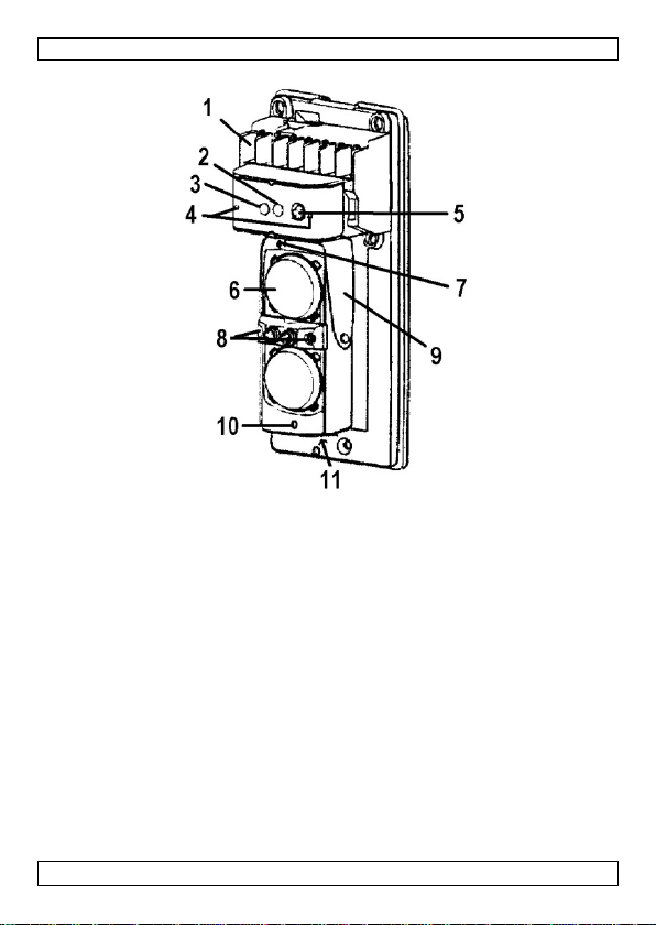
1
Terminals
7
Vertical adjustment screw
2
Signal LED (only o n receive r)
8
Viewfinder
3
Alarm LED (only on receiver)
9
Horizontal adjustment bracket
(9 0° left and right)
4
Voltage me asuring points
10
Ad just ment laser
5
Delay time adjustment knob
11
Laser on/off switch
6
Sensor
USER MAN UAL
1. Introduction
To all re sidents of th e Euro pean Union
Important environmental information about this product
If in do ubt, contact your local waste dispo sal authorities.
Thank you for choosing Velleman! Please read the manual thoroughly before
bringing this device into service. If the device was damaged in tr ansit, don't
insta ll or use it and conta ct your dealer.
2. Safety Instructions
• Make sure that the voltage supply does not exceed the rated value.
• Keep the cables well clear of other current-carrying conductors in order
• Do not install th e se nsor where it is exposed to fluorescent lamps with
• Do not expose the device to dust, water, dirt or oil and protect it f rom
3. Overview
Refer to the illustrations on page 2 of this ma nual .
This symbol on t he device or the package indicat es that disposal of
the device after its lifecycle could harm the environment. Do n ot
dispose of the unit ( or batteries) as uns orted munic ipal waste; it
should be taken to a specialized company for recycling. This device
should be returned to your distributor or to a local recycling
service. Respec t the local enviro nmental rule s.
to avoid the creation of mag netic fields which may ca use in terference.
rapid-starters or high-frequency starters.
vibrations or shocks to prevent malfunction.
(1 5° up and down )
(only on receiver)*
(only on receiver)
*There is a power LED to the left of this block on both units
V. 02 – 27/11/2013 3 ©Velle man nv
Page 4

PEM300D
Voltage
Wire / s ize
12V
24V
AWG22
m
320
2800
0.52mm²
ft
1800
12750
AWG18 m 800
7200
4. Mounting Location
• Make sure there are no obstructions between the transmitter and the
receiver (tr ees, bushes, clotheslines etc.).
• Avoid strong lig ht (sun, car headlights, etc.) s hinin g direct ly on
transmitter or receiv er. When strong light stays in the op tical axis for a
long time, it does not cause malfunction but will reduce the product life.
• Do not install the units where they may be affected by dirty water or
direct sea spray.
• Do not install the units on unsteady surfaces.
• The receiver has to be placed within the detection range (30m/100ft)
and the spread of the beam (∅ 0.9m/3 ft at 30m/1 00f t) of the
transmitter.
• Install the sensors at a height of 0.8 to 1m (± 3ft), the ideal height to
capture human passers-by.
• Wi th the sensor block adjustments ([7] and [9] i n the pi cture ab ove ), a
large variety of mounting com binations are possible. See "6. Alignment"
for guidelines.
5. Wiring / Contacts
• Terminal connection 1 is the power 10 to 30V DC + line on both units.
Terminal conne ction 2 is the power 10 to 30V DC - line on both units.
The power lines need to be connected to these terminals.
• Terminal connections 6 and 7 form a tamper outp ut ; they are
connected through a dry contact relay.
When the cover is taken off, there is no contact.
No wires need to be connected to these terminals.
• On the receiver, terminal 3 is norma lly connect ed to terminal 4 and in
the event of detection, contact with terminal 4 is broken and contact
with terminal 5 is established.
It depends on how your control panel works if you need to connect
either terminals 3 and 4 or terminals 3 and 5 to the control pa ne l.
Max imum wiring d istance
When two or more sets are connected , the maximum cable length is as
shown abov e di v i de d by the num be r of sets.
0.33mm²
AWG20
V. 02 – 27/11/2013 4 ©Velle man nv
ft
m
1050
550
18000
4800
Page 5

PEM300D
0.83mm²
ft
2600
23620
AWG17
m
980
8800
1.03mm²
ft
3190
28870
6. Installing the device
• Unscrew the attachment screw at the bottom of the cover and lift it off
the rest of the unit.
• When the cover is off, unscrew the attachment screw at the bottom of
the main part of the unit (holding the mounting plate) and remove the
mounting plate by sliding it downwards.
• If the wiring comes out of the mounting wall, break through the rubber
gromm e t on the mo un ti ng pla te, pul l the wire throu gh a nd fi x the
mounting plate to the wall using 2 of the provided tapping screws. Make
sure to seal any gap between the wires and the grommet.
• If the wiring is 'exposed' (i.e. on the wall), fix the mo unting plate on the
wall at the desired location, bre ak the knockouts at the left side on the
back of the main unit (upper or lower ones, depending on where the
wiring comes from) and place the wiring in the knocked out openings.
• Pul l the wiri ng throug h the ho u sing (a t the t op righ t, see n fr om the
back), attach the wires to the correct terminals, and fix the unit to the
mounting plate.
• Adjust alignment of the units (see "6. Alignment"), check the operation
and put the c over ba ck on.
• No sealing is required since the housing is designed to be waterproof.
7. Alignment
Sensor Ad just m ent
1. Take the covers off both uni ts.
2. Look into one of the transmitter's viewfinders (the 4 holes between the
2 sensors, [8]).
3. Ad just the angle of the sensor bloc k horizontally (brack et [9]) and
vertically (screw [7]) until you can clearly see the receiver in the
viewfinder.
4. Repeat st eps 2 and 3 with the receiver, loo king for the transmitter.
5. Put the covers back on t he uni ts.
Laser Adjustment
Warning: never loo k directly int o the laser beam.
1. Take the cove r s off both uni t s.
2. Switch on the receiver's laser (swit c h [11] ; beam [10]). A red dot will
indicate where the beam is aimed.
3. Aim the receiver's sensor block so the red dot is centred on the
transmitter.
4. Turn the receiver's laser off.
V. 02 – 27/11/2013 5 ©Velle man nv
Page 6

PEM300D
Possible cause
Solution
1
No power supply .
Connect the power lines.
2
Bad wiring.
Check and r epair the po wer lines.
Possible cause
Solution
1
No power supply .
Connect the power lines.
5. Switch on the transm itter's laser ([11] and [10]). A red dot will show
where it is aimed at.
6. Adjust the angle of the sensor block horizontally and v ertically ([9] and
[7]) until th e red dot is centred on the receiver and both the receiver' s
LEDs ([2] and [3]) go out.
7. You may have to adjust th e angle of the receiver's sensor blo c k a little
as well.
8. Turn the transmitter's la ser off.
9. Put the covers back on t he uni ts.
Fine-tuning the Receiver
1. Take the cover of f the receiver.
2. The units can be fine tuned using a volt-ohm meter (VOM).
3. Set the range of the VOM to 0~10V DC.
4. Measure the voltage over the + and - measuri ng poin t s [4] on the
receiver.
5. Adjust the angle of the sensor block until the VOM measures the
highest voltage.
6. 2.5 to 5 V is OK, 5 to 8 V is best.
7. Put th e cover back on the receiver.
Delay T ime
1. Take the cover of f the receiver.
2. Adjust the delay time with the knob on the receiver [5].
Objects passing faster than the selected delay time will not be
detected.
A delay tim e of 50 ms corresponds to someone running by at full
speed.
A delay tim e of 700 ms corresponds to someone walking by.
3. Put the cover back on the receiver.
When finished tuning and adjusting the units, put the covers back on and fix
them with the bottom screw.
8. Troubleshooting
Power LED do es not light up
Alarm LE D do es not light up when the be am is interrupted
2 Bad wiring. Check and r epair the po wer lines.
V. 02 – 27/11/2013 6 ©Velle man nv
Page 7

PEM300D
3
Beam is reflected on another
receiver.
Remove the reflecting object or
4
The 2 beams are not broken
simultaneously.
Adjust beam direction so they're
broken simultaneously.
5
The beam interrup tion time is
Set a shorter delay time
Possible cause
Solution
1
Deregulated alignment.
Real i gn the unit s.
2
Object between the 2 units.
Remove object or relocate units.
3
Unit sensors are dirty.
Clean the sensors with a soft cloth.
Possible cause
Solution
1
Bad wiring.
Check and repair wiring.
2
Unstable power suppl y .
Stabilize power supply.
3
Object between the 2 units.
Remove object or relocate units.
4
Electronic noise source nearby.
Remove noise source or relocate units.
5
Unstable installation of units.
Stabilize installation locat ion.
7
Deregulated alignment.
Real i gn the unit s.
8
Small animals pas s by.
Set a longer delay time.
power suppl y
10 - 30V DC (n ot incl.)
response time
50 ms - 700 ms (variable)
alarm output
NC/NO 1A / 120 Vac
tampe r o ut put
NC 1A / 120 Vac
LED indicators
- alarm LED (receiver):
when b eam is broken
green LED on - indic ates that device is ON
wavelength
650 nm
laser output power
max. 5 mW
object and sent into the
shorter than the delay time.
change the beam direction.
Alarm LE D lights up continuo usly
Inte rmitt ent false ala rm sign als
6 Unit sensors are dirty. Clean the sensors with a soft cloth.
9. Technica l Specifications
detection system simultaneous breaking of 2 IR-b eams
red LED on - when transmitter and receiver are not
- signal LED (receiver):
- power LED (transmitter & receiver):
aligned or when beam is broken
yellow LED on - when receiver's signal is weak or
V. 02 – 27/11/2013 7 ©Velle man nv
Page 8

PEM300D
IP ratin g
IP44
alignment range
horizontal: ± 90°
vertical: ± 15°
op erating temperature
-25°C to +55°C
dimensions
170.5 x 74 x 72 mm
weight
1.1 kg
Use this devic e w ith origina l accesso ries o nly. Velleman nv cann ot
be held res ponsible in the event of dama ge or inju ry resulting from
(incorrect) use of this device.
For mo re info concerning this product and t he la test ve rsion of th is
manual, please vis it o ur web site www.ve lleman .eu.
The information in this manual is subject to change without prior
notice.
© COPYRIGH T NOTICE
The copyrig ht to this manu al is own ed by Ve lleman nv. All
worldwi de rights res erved. No part of this manual may be copied,
reproduced, translated or reduced to any electronic medium or otherwise
without the prior written consent of the copyright holder.
V. 02 – 27/11/2013 8 ©Velle man nv
Page 9

PEM300D
1
Terminals
7
Schro ef voor verticale regeling
(15° op en neer)
2
Signaalled (enkel op d e
8
Zoeker
3
Alarmled (enkel op de
9
Beugel voor horizontale
4
Meetpunten voor de spanning
(enkel op de ontvanger)*
10
Laser voor regeling
5
Vertragingsregelaar (enkel op
11
Laser aan/uit-schakelaar
6
Sensor
GEBRUIKERSHANDLEIDING
1. Inleiding
Aan alle ingezetenen van de Europese Unie
Belan grijke milieu-informatie betreffende dit product
brengen. Respecteer de plaatselijke milieuwetgeving.
Hebt u vragen, contacteer dan de plaatselijke autoriteiten
betreffende de verwijdering.
Dank u voor uw aankoop! Lees deze handleiding grondig voor u het toestel
in gebruik neemt. Werd het toestel beschadigd tijdens het tran s po rt,
installeer het dan niet en raadpleeg uw dealer.
2. Veiligheidsinstructies
• De voedingsspanning mag de meetwaarde niet overschrijden.
• Houd de kabels uit de buurt van andere stroomvoerende geleiders. De
• Stel de senso r niet rechtstreeks bloot aan fluorescent ielampen met
• Stel het toestel niet bloot aan stof, water , olie o f vuil. Bescherm het
3. Omschrijving
Raadpleeg de afbeeldingen op pagina 2 van deze handleiding.
Dit symbool op het toestel of de verpakking geeft aan dat, als het
na zijn levenscyclus wordt weggeworpen, dit toestel schade kan
toebrengen aan het milieu. Gooi dit toestel (en eventuele
batterijen) n iet bij het gewone huishoudelijke afva l; h et moet bij
een gespecialiseerd bedrijf terechtkomen voor recyclage. U moet
dit toestel naar uw verdeler of naar een lokaal recyclagep unt
magnetische velden die zouden ontstaan, kun nen s tori ngen
veroorzaken.
snelstar te rs of ho ogf r e quente sta r te rs.
toestel tegen hevige trillingen of schokken om defecten t e vermijden.
ontvanger)
ontvanger)
de on tva nger)
V. 02 – 27/11/2013 9 ©Velle man nv
regeling (90° links en rechts)
Page 10

PEM300D
Spanning
Draad / dikte
12 V
24 V
*Er bevindt zich een voedingsled links van dit blok op beide toestellen
4. Montageplaats
• Zorg ervoor dat er geen storende elementen tussen de 2 toestellen
staan (bomen, struiken, waslijnen etc.).
• Zorg ervoor dat er geen sterk licht (zon, koplampen etc.) direct op de
zender of ontvanger kan schijnen. Als een sterk licht lange tijd in de
optische as schijnt, zal dit geen foute detectie opleveren, maar zal het
wel de levensduur van de toestellen inkort en.
• Plaats de toestellen niet waar ze aangetast kunnen worden door vuil
water of directe zeenevel.
• Installeer de toestellen niet op onstabiele ondergronden.
• Plaats de ontvanger binnen het detectiebereik (∅ 0.9m/3f t op
30m/10 0f t) van de zen der.
• Plaats de sensoren op een hoogte van 0,8 tot 1 m, de ideale hoogte om
menselijke voorbijgangers te bespeuren.
• Met de regelingen van het sensorblok ([7] en [9]), is een groot aantal
mont ageco mbinaties mogelijk. Zie "6. Afstelling" om de toestelle n
precies af te regelen.
5. Bedrading / Contactpunten
• Con ta ctpun t 1 is v o or de 1 0 to t 3 0 V D C p o si tieve voed i ngska be l op
beide toestellen.
Con ta ctpun t 2 is v o or de 1 0 to t 3 0 V D C ne gatie v e voe d i n g ska b e l op
beide toestellen.
De voedingskabels moeten op deze contactpunten aangeslot en worden.
• Contactpunten 6 en 7 vormen een 'knoeibeveiliging': ze zijn verbonden
door een droog contactrelais.
Als de afdekkap verwijderd wordt, is er geen cont act.
Op deze contactpunten dienen geen draden aangesloten te worden.
• Op de ont vanger is contact punt 3 normaa l verbonden met contactpunt 4
en als er een detectie gebeurt, wordt het contact met contactpunt 4
verbroken en wordt er contact gemaakt met contactpunt 5.
Het hangt dus van uw co ntrolepaneel af of u contactpunten 3 en 4 of
contactpunten 3 en 5 dient aan te sluiten op uw controlepaneel.
Maximale bedradingafstand:
Opmerking: als er twee of meer sets aangesloten worden, moet de
maximale kabellengte zoals hierboven aangegeven gedeeld worden door het
aant al sets.
V. 02 – 27/11/2013 10 ©Velle man nv
Page 11

PEM300D
AWG22
m
320
2800
AWG20
m
550
4800
AWG18
m
800
7200
AWG17
1.03 mm²
m
ft
980
3190
8800
28870
0.33 mm²
0.52 mm²
0.83 mm²
ft
ft
ft
1050
1800
2600
18000
12750
23620
6. Het to estel ins talleren
• Draai de schroef onderaan de afdekkap los en verwijder de kap van de
rest van het toestel.
• Als deze verwijderd is, draai dan de schroef onderaan het toestel (die
het toestel op de montageplaat vastzet) los en verwijder de
mon tageplaa t do or de ze naa r be ne de n te gl i jde n.
• Als de bedrading uit de muur komt, doorprik dan de rubberen
pakk i ngr i ng o p de montagepla a t, tre k de be drading erd o or en zet de
montageplaat vast op de muur met 2 van de meegeleverde schroeven.
Dicht eventuele gaten tussen de bedrading en de pakkingring.
• Als de bedrading 'blootligt' (dus op de muur), zet dan eerst de
mon tageplaa ts va s t op de gew e n s te pl a a ts op de muu r, bre ek de
voorgesneden doorsteekgaten aan de linkerkant achteraan het toest el
(bo ven- of ond e raan, afhankelijk van welke kant de bedrading ko mt) en
pla a ts de bedr ading in de vri jge m a akte openi n ge n.
• Steek de be drading d o or de be huizin g (re c h t s bove n aa n, van de
achterkant gezien), maak de draden vast aan de juiste contactpunten,
en maak het toestel vast aan de montagep laat.
• Regel de oriëntatie van de toestellen (zie "6. Afstelling" op blz. 7),
controleer of ze werken en plaats de afdekkap terug.
• Ext ra afdichting is niet nodig w ant de behuizing is spa twate rdicht.
7. Afstelling
Regeling van de sensor
1. Verwijder de afdekkap van beide toestellen.
2. Kijk in 1 van de zoekers van de zender (de 4 gaten tussen de 2
senso rs, [8]).
3. Regel de hoek van het sensorblok horizontaal (beugel [9]) en verticaal
(schroef [7]) tot u de ontvanger duidelijk kunt zien in de zoeker.
4. Herhaal stappen 2 en 3 met de ontvanger, op zoek naar de zender.
5. Plaats de afdekkappen terug op de toestellen
Rege ling van de laser
WAARSCH UWING : kijk nooit rechtstree ks in de laserstraal!
1. Verwijder de afdekkap van beide toestellen.
V. 02 – 27/11/2013 11 ©Velle man nv
Page 12

PEM300D
Mogelijke oorzaak
Oplossing
1
Geen voed ing.
Verbi n d de stroomdraden.
2
Sle ch te be drading.
Controleer en herstel de bedrading.
2. Zet d e laserstraal van de ontvanger aan (schakelaar [11]; straal [10]).
Een rode stip duidt aan naar waar de straal gericht is.
3. Richt het sensorblok van de ontva nger horizontaa l en verticaal tot de
rode stip in het midden van de zender terechtkomt.
4. Zet d e laserstraal van de ontvanger af.
5. Zet d e laserstraal van de zender aan ([11] en [10]). Een rode stip
duidt aan naar waar d e straal gericht is.
6. Regel de hoek van het sensorblok horizontaal en verticaal ([9] en [7])
tot de rode stip in het midden van de zender terechtkomt en beide leds
op de ontvanger ([2] en [3]) doven.
7. Het is mogelijk dat het sensorblo k van de ont v anger nog een beetje
bijgeregeld dient te worden.
8. Zet de laser van de zend er af.
9. Plaats de afdekkappen terug op de toestellen.
Fijnregeling van de ontvanger
1. Verwijder de afdekkap van de ontvanger.
2. U kunt de toestellen verd er haarfijn afregelen met behulp van een
vo ltohm meter (VOM).
3. Zet het b ereik van de VOM op 0~10V DC.
4. Meet de spanning over de + en - meetpunten [4] op de ontvanger.
5. Regel de hoek van het sensorblok tot de VOM de hoogst mogelijke
spanning meet.
6. Tussen 2,5 en 5 V is OK, tussen 5 en 8 V is ideaal.
7. Plaats de afdekkap terug op de ontvanger.
Vertraging
1. Verwijder de afdekkap van de ontvanger.
2. Regel de vertraging met de knop op de ontvanger [5].
Voorwerpen die sneller passeren dan de ingestelde vertraging zullen
niet gedetecteerd worden.
Een vertraging van 50 ms komt overeen met iemand die aan volle
snelheid voorbij komt gespurt.
Een vertraging van 700 ms komt overeen met iemand die voorbij komt
gewandeld.
3. Plaats de afdekkap terug op de ontvanger.
Als u de toestellen volledig afgeregeld hebt, plaats dan de afdekkappen
terug en zet ze vast met de schroef onderaan.
8. Problemen en oplossinge n
Voedingled licht n iet op
V. 02 – 27/11/2013 12 ©Velle man nv
Page 13

PEM300D
Mogelijke oorzaak
Oplossing
1
Geen voed ing.
Verbi n d de str oom d r ade n .
2
Sle ch te be drading.
Controleer en herstel de bedrading.
weerkaatst naar de ontvanger.
richting van de stralen.
4
De 2 stralen worden niet
Regel de richting van de stralen zodat
5
De straa l onder bre ki ng duur t
Stel een kortere vertraging in.
Mogelijke oorzaak
Oplossing
1
Afstelling is ontregeld.
Stel de toestellen opnieuw af.
2
Voorwerp tussen de toestellen.
Verwijder voorwerp of verplaats
3
Sensors zijn vuil.
Reinig de sensors met een zachte
Mogelijke oorzaak
Oplossing
1
Sle ch te be drading.
Controleer en herstel de bedrading.
2
Onstabiele v oeding.
Stabilisee r de vo eding.
3
Voorwerp tussen de toestellen.
Verwijder voorwerp of verplaats
toestellen.
5
Onstabiele installatie van
Stabilisee r installatie van de toestellen.
6
Sensors zijn vuil.
Reinig de sensors met een zachte
7
Afstelling is ontregeld.
Stel de toestellen opnieuw af.
8
Kleine dieren onderbreken de
stralen.
Stel een langere vertraging in.
voeding
10 - 30V DC (niet meegelev.)
detectiesysteem
simultane onderbreking van 2 IR-stralen
responstijd
50 ms - 70 0 ms (instelbaa r)
Alarmled licht niet op wanneer de str aal onderbroke n wordt
3 Straal wordt via een voorwerp
tegelijkertijd onderbroken.
korter dan de ingestelde
vertraging.
Verwijder het voorwerp of verander de
ze samen onderbroken worden.
Alarmled blij ft co ntinu aan
toestellen.
Rege lma tige va lse alarmsign alen
4 Elektronische storingbron in de
buurt.
doek.
Verwijder s tori ngbr on of verpl aat s
toestellen.
toestellen.
doek.
9. Technische specificaties
V. 02 – 27/11/2013 13 ©Velle man nv
Page 14

PEM300D
alarmuitgang
NC/NO 1A / 120 Vac
antisabotage-uitgang
NC 1A / 12 0 Vac
afgestel d of de s tra a l is onde rbroken.
het si gnaa l van de ontvanger i s zwak
of straal is onderbroken.
- voedingsled (zender & ontvanger):
golflengte
650 nm
uitgangsvermogen
IP-norm
IP44
uitlijnbereik
ho rizontaal: ± 90°
verticaal: ± 15°
werktemperatuur
-25°C tot +55°C
afmetingen
170.5 x 74 x 72 mm
gewicht
1.1 kg
LED-indicators - alarmled (ontvanger):
rode led aan - de toestellen zijn niet op elkaar
- signaalled (ontvanger):
gele led aan -
groene led aan - het toeste l is ingeschakeld.
laser
max . 5 mW
Gebruik dit toestel enkel met or iginele accessoires. Velleman nv is
niet aansprakelijk voor schade of kwetsuren bij (verkeerd) gebruik
van dit toestel.
Voor meer informa tie over dit product en de laatste ver sie van deze
handleiding, zie www.velleman.eu.
De in formatie in d eze ha ndleiding kan te allen tijde wo rden
gewijzigd zonder voorafgaande kennisgeving.
© AUTEURSREC HT
Velleman nv heeft het auteursrecht voo r deze handleiding. Alle
wereldwijde rechten voorbehouden. Het is niet toegestaan om deze
handleiding of gedeelten ervan over te nemen, te kopiëren, te vertalen, te
bewerken en op te slaan op een elektronisch medium zonder voorafgaande
schriftelijke toestemming van de rechthebbende.
V. 02 – 27/11/2013 14 ©Velle man nv
Page 15

PEM300D
1
Bornes
7
Vis pour réglage verticale (15°
2
LED signa l (unique m en t sur le
8
Viseur
3
LED alarme (uniq uement sur
9
Etrier pour réglage horizontal
4
récepteur)*
10
MODE D 'E M PLOI
1. Introduction
Aux résidents de l'Union européenne
Informations environnementales importantes concer nant ce p roduit
Il convient de respecter la ré glementation loca le relative à la protect ion de
l'environnement.
En ca s de doute, contact er les autorité s lo cales p our élimination.
Nous vous remercions de votre achat ! Lire le pr ése nt mode d'em ploi
attentivement avant la mise en service de l'appareil. Si l'appar eil a été
endommagé p end ant le transpor t, ne pas installer et consulter votre
revendeur.
2. Consi gnes de sécurité
• La tension d'alimentation ne peut pas dépasser la valeur de mesure.
• Tenir les câbles à l'écart de tout autre conducteur électrique sous
• Evit er l'e xposition directe d e l'appareil aux tubes fluore scents pourvu s
• Evit er d'exposer l'appa reil aux poussières et salissures, à l'eau ou à
3. Description
Se réf érer aux figures en page 2 de ce mode d'emploi.
Ce sym b ole sur l'a p pa reil ou l'emballage in dique que l'élimination
d'un appareil en fin de vie peut polluer l'environnement. Ne pas
jeter un appareil électrique ou élect ronique (et des piles
éve ntuel l es) parm i les déchets mu ni ci pa ux non suje t s au tri
sélectif; une déchèterie traitera l'appareil en question. Renvoyer
cet appareil à votre fournisseur ou à un service de recyclage local.
tension pour éviter la formation de champs magnétiques, qu i p ourraient
occasionner des interférences.
de démarreurs électriques ultr arapides ou haute fréquence.
l'huile. Protéger l'appa reil des chocs ou des vibr ations pour évit er tout
endommagement d e l'appareil.
vers le haut et vers le bas)
récepteur)
le récepteur)
Point s de me sure p our la
tension (uniquement sur le
(90° gauche et droit)
Laser pour réglage
V. 02 – 27/11/2013 15 ©Velle man nv
Page 16

PEM300D
5
Réglage de d élai (uniquement
11
Interrupteur laser
6
Capteur
sur le récepteur)
*Il y a une LED de puissance à gauche de ce bloc sur les deux appareils
4. Lieu de montage
• Veiller à ce qu'il n'y a pas d'éléments perturbants entre les deux
appareils (arbres, buissons, corde à linge etc.).
• Veiller à ce qu'aucune lumière forte (soleil, phares etc .) ne puisse briller
directement sur l'un des deux appareils. Une lumière forte qui brille
longtemps dans l'axe optique ne va pas causer de détections fautives,
mais va raccourcir la durée de vie des appareils.
• Ne pas installer les a ppareils où ils sont exposés à de l'e au sale ou de la
vaporisation de mer directe.
• Ne pas installer les a ppareils sur des surfaces instables.
• Installer le récepteur dans la portée de détection (∅ 0.9m/3ft sur
30m/100ft) de l'émetteur.
• Installer les détecteurs sur une hauteur de 0,8 à 1 m, c'est la haut eur
idéale pour détec ter des passa nt s humai ns.
• Puisque le bloc à capteurs est réglable (voir [7] et [9]), un g rand
nombre de combinaisons de montage est possible. Consulter "6.
Réglage" pour aligner les appareils précisément.
5. Câblage / Contacts
• Contact 1 es t pour le câ ble de pu issance positif 10 à 30V CD sur les
deux appareils.
Contact 2 est pour le câble de puissance négatif 10 à 30V CD sur les
deux appareils.
Les câbles de puissance doivent être branchés sur ces contacts.
• Contacts 6 et 7 constituent une protection contre le tripotage: ils sont
liés par un relais de contact sec.
Quand le co uv ercle est enlevé, il n'y a plus de contact.
Ne pas connecter des câbles à ces contacts.
• Sur le récepteur, le contact 3 est normalement connecté au contact 4.
Quand il y a une détection, le contact avec contact 4 est interrompu et
un contact avec contact 5 est établi.
Vot re panneau de contrôle va donc déterminer s'il est nécessaire de
connecter les contacts 3 et 4 ou aux contacts 3 et 5.
Distance maximale de câblage :
Lorsque v ous connecter 2 ensembles ou plus, divise r la longueur m aximale
mentionnée ci-dessus par le nombre d'ensembles.
V. 02 – 27/11/2013 16 ©Velle man nv
Page 17

PEM300D
Tension
Câbl e /
12 V
24 V
AWG22
0.33 mm²
m
ft
320
1050
2800
18000
0.52 mm²
ft
1800
12750
AWG18
m
800
7200
AWG17
1.03 mm²
m
ft
980
3190
8800
28870
diamètre
AWG20
0.83 mm²
m
ft
550
2600
4800
23620
6. Installer l'appareil
• Dévisser la vis en bas du couvercle et enlever le couvercle de l'appareil.
• Après avoir enlevé le couvercle, dévisser la vis en bas de l'appareil (qui
attache l'appareil à la plaque de montage) et enlever la plaque de
mont age en la glissant vers le bas.
• Si le câbla ge sort du mur, p ercer le joint en caoutchouc sur la plaque de
montage, faites passer les câbles et attacher la plaque de montage au
mur avec les 2 vis incluses. Boucher les trous évent uels entre le câblage
et le joint.
• Si le câbla ge est 'exposé' (se tro uv e donc sur le mur), fixer d'abord la
plaque de montage au mur à l'emplacement souhaité, percer les trous
de passage prédécoupés au côté gauche du derrière de l'appareil (en
haut ou en bas, dépendant d'où viennent les câbles) et insérer le
câblage dans les trous percés.
• Passer le câblage à travers le boîtier (en haut à droite, vu du derrière),
attacher les câbles aux contacts corrects et fixer l'appareil à la plaque
de mont age.
• Aligner les appareils (voir "6. Réglage"), vérifier s'ils fonctionnent et
remettre le couvercle.
• Un co lmatage additionnel n'est pas nécessaire car le boîtier est étanche.
7. Réglage
Réglage des capteurs
1. Enlever les couvercles des deux appareils .
2. Regarder dans 1 d es viseurs de l'émetteur (les 4 trous entre les 2
capt eurs, [8]).
3. Régler l'angle du bloc de capteurs horizontalement (étrier [9]) et
verticalement (vis [7]) jusqu'à ce que vous puissiez clairement voir le
récepteur dans le viseur.
4. Répéter les étapes 2 et 3 avec le récepteur, en cherchant l'émetteur.
5. Remettre les couvercles sur les appar eils.
V. 02 – 27/11/2013 17 ©Velle man nv
Page 18

PEM300D
Cau se pos sible
Solution
Réglage du laser
ATTENTION : ne jamais regarder directement dans le rayon laser !
1. Enlever les couvercles des deux appareils .
2. Allumer le rayon laser du récepteur (interrupteur [11] ; rayon [10]).
Un point rouge marque vers où est dirigé le rayon.
3. Ajuster le bloc de capteurs horizontalement et verticalement ([9] et
[7]) jus qu 'à ce que le point rouge se trouve au milieu d e l' émetteur.
4. Eteindre le rayon laser du récepteur.
5. Allumer le rayon laser de l'émetteur ([11] et [10]). Un point rouge
marque vers où est dirigé le rayon.
6. Ajuster le bloc de capteurs horizontalement et verticalement ([9] et
[7]) jus qu 'à ce que le point rouge se trouve au milieu d u récepteur et
les deux LEDs du récepteur ([2] et [3]) s'éteignent.
7. Il se peut que le bloc de capteurs du récepteur doive encore être
aju sté un pe tit peu.
8. Eteindre le rayon laser de l'émetteur .
9. Remettre les couvercles sur les appar eils.
Réglage fin du récepteur
1. Enlever le couvercle du récepteur.
2. Il est pos sible d'a just er les appareils avec un mètre volt-ohm. (MVO).
3. Sélectio nner 0~10V CD comme portée du MVO.
4. Mesur er la tension entre les points de mesure + et - ([4]) sur le
récepteur.
5. Ajuster l'angle du bloc de capteurs jusqu'à ce que le MVO registre la
tension la plu s haute possible.
6. Entre 2,5 et 5 V est OK, entre 5 et 8 V est idéal.
7. Remettre le couver c le sur le récepteur.
Délai
1. Enlever le couvercle du récepteur.
2. Régler le délai avec le bouton sur le récepteur ([5 ]).
Des objets qui passent plus vite que le délai sélectionné ne seront pas
détectés.
Un délai de 50ms correspond à quelqu'un qui passe en sprintant à
toute vitesse.
Un délai de 700ms correspond à q uelqu'un qui passe en se promenant.
3. Remettre le couver c le sur le récepteur.
Après av oir aligné les appareils, remettre les couvercles et fixer-les ave c la
vis en b a s.
8. Pro b lèmes et sol utions
La LED de puis san ce ne s' allume pas
V. 02 – 27/11/2013 18 ©Velle man nv
Page 19

PEM300D
1
Pas d'alimentation.
Co nnecter les c âbles d'aliment ation.
2
Câblage défectueux.
Vérifier et réparer le câblage.
Cau se pos sible
Solution
1
Pas d'alimentation.
Connecter les câbles d'alimentation.
2
Câblage défectueux.
Vérifier et réparer le câblage.
3
Rayon est renvoyé par un objet
Eloigner l'objet ou changer la direction
4
Les 2 rayons ne sont pas
Régler la direction des rayons pour
5
L'interruption du rayon est plus
Sélectionner un délai plu s bref.
Cau se pos sible
Solution
1
Réglage est déréglé.
Régler les appareils de nouveau.
3
Les capteurs sont sales.
Nettoyer les capteurs avec un chiffon
Cau se pos sible
Solution
1
Câblage défectueux.
Vérifier et réparer le câblage.
2
Alim en tation instable.
Stabiliser l' alimentation.
appareils.
appareils.
4
Source proche de bruit
Eliminer le bruit ou dépla cer les
5
Installation instable des
Stabiliser l' installation des appareils.
7
Réglage est déréglé.
Régler les appareils de nouveau.
8
Des animaux interrompent les
Sélectionner un délai plu s long.
La LED d'alarme ne s'allume pas lorsque le rayon est int errompu
vers le récepteur.
interrompus sim ultaném ent.
brève que le délai sélectionné.
des ra yo ns.
qu'ils soient interrompus
simultanément.
La LED d'alarme s' allume en con tinu
2 Il y a un objet entre les
appareils.
De fausses alertes fréquentes
3 Il y a un objet entre les
électronique.
Eloigner l'objet ou déplacer les
appareils.
doux.
Eloigner l'objet ou déplacer les
appareils.
appareils.
6 Les capteurs sont sales. Nettoyer les capteurs avec un chiffon
doux.
rayons.
9. Spécifications techniques
alimentation 10 - 30 V CC (no n inc l .)
V. 02 – 27/11/2013 19 ©Velle man nv
Page 20

PEM300D
système de détection
interruption simult anée de 2 rayons IR
temps de réponse
50 ms - 70 0 ms (réglab le)
sortie d'alarme
NC/NO 1A / 120 Vca
sortie anti-sabotage
NC 1A / 12 0 Vca
Indicateurs LED
- LED d'alarme (récepteur) :
- LED de signal (récepteur) :
- LED d'alimentatio n (émetteur & récepteur) :
longue ur d' on de
650 nm
puiss ance de sortie du
laser
max . 5 mW
norme IP
IP44
an gle d'alignement
horizontal : ± 90°
vertical : ± 15°
température de travail
de -25°C à +55°C
dimensions
170.5 x 74 x 72 mm
poids
1.1 kg
LED rouge s'allume - les appareils ne sont pas
alignés ou le rayon est interrompu
LED jaune s'allume - le signal du récepteur est
faible o u le rayon est interrompu.
LED vert s'allume - l'appareil est sous tension
N'employer cet appareil qu'avec des accessoires d'origine. La SA
Velleman ne peut, dans la mesure conforme au droit applicable être
tenue responsable des dommages ou lésions (directs ou indirects)
pouvant ré sulter de l’ utilis atio n de cet appare il.
Pou r plus d'informations concernant cet article et la dernière
version de ce mod e d'emploi, cons ulte r notr e site www.velle man.eu.
Les spécifications et le contenu de ce mode d'emploi peuvent être
modif iés s ans avis préa lable.
© DROITS D’AUTEUR
SA Velle man e st l’ay ant droit des d roits d’ aut eur pour ce mode
d'emploi. Tous droits mondiaux réservés. Toute repr o duction,
traduc tion, copie ou d iffusion, intégrale ou partielle, du conte nu de ce mode
d'emploi par quelque procédé ou sur tout support électronique que ce soit
est interdite s ans l’ accord préa lab le éc rit de l’ayant droit.
V. 02 – 27/11/2013 20 ©Velle man nv
Page 21

PEM300D
1
Terminales
7
Tornillo para la alineación
hacia abaj o)
2
LED de s eñal (sólo receptor)
8
Visor
3
LED d e alarma (sólo recept or)
9
Alineación horizontal (90°
izquierda y derecha)
4
de t ensión (sólo receptor) *
10
5
Potenciómetro para ajust ar el
11
Interruptor ON/OFF para el
6
Sensor
MANUAL D E L USUAR I O
1. Introducción
A los ciuda danos de la Unión Europea
Importantes informaciones sobre el medio ambiente concern iente a
este producto
Si tiene dud as, conta cte con las autorid ades loc ales para re siduos.
¡Gracias por elegir Vellem an! Lea atentamente las instrucciones del manual
antes de usar el aparato. Si el aparato ha sufrido algún daño en el
transp orte no lo instale y póng ase en contacto con su distribuidor.
2. Instrucciones de seguridad
• Asegúrese de que la tensión de la alimentación no supere el valor que
• Mantenga los cables lejos de otros conductores de corriente, con el fin
• No instale el senso r en sitios donde pueda estar expuest o a lámparas
• No exponga el aparato a po lvo, agua, suciedad o aceite y protéjalo
3. Descripción
Véase las figuras en la página 2 de este manual d el usuario.
Este símbolo en este aparato o el embalaje indica que, si tira la s
muestras inservib les, pod rían dañar el m edio ambiente. No t ire
este ap arato (ni las pilas, si las hubiera) en la basura doméstica;
debe ir a una empresa especializad a en reciclaje. Devuelva este
aparato a su distribuidor o a la unidad de reciclaje local. Respete
las leyes locales en relación con el medio ambiente.
figura en las especificaciones del manual d el usu ario.
de evitar campos magnéticos que podrían causar interferencias
fluorescentes de arranque rápido o de alta frecuencia.
contra vibraciones o golpes para evitar un malfuncionamiento.
vertical (15° hacia arriba y
Co ntacto s para medir el nivel
tiempo de respuesta (sólo
receptor)
V. 02 – 27/11/2013 21 ©Velle man nv
Rayo láser para la alineación
láser
Page 22

PEM300D
alimentación
Cabl e /
dimensiones
12V
24V
AWG22 m 320
2800
*Hay un LED de alimentación en la part e izq uierda de este bloque en ambas
unidades.
4. Lugar de montaje
• Quite cualquier obstáculo (árboles, arbustos, cuerdas par a tender la
ropa, etc.) entre el emisor y el receptor.
• Evite luces fuertes (sol, faros etc.) que brillen directament e en el
transmisor o en el receptor. Si una luz fuerte permanece durante un
largo perí odo de tiempo en el eje óptico, no causará un
malfuncionamien to del mismo, pero disminuirá la d uración de vida de
los aparatos.
• No instale los aparatos donde estén expuestos a agua salada o
vaporización directa de l mar.
• No instale los aparatos en superficies inestable s.
• Instale el receptor dentro del rango de detección (30m/100ft) y el rayo
de luz (∅ 0.9m/3ft a 30m/100ft) del emisor.
• Instale los sensores en una altura de 0.8 a 1 m (± 3ft). Esto es la altura
ideal para detectar personas.
• Hay muchas posibilidades para montar el aparato gracias a la alineación
vertical [7] y horizontal [9] (véase "6. Alineación").
5. Hi lo / Terminal es
• Terminal 1: alimentación 10 a 30V DC + (r eceptor y emisor )
Terminal 1: alimentación 10 a 30V DC - (receptor y emisor)
Conecte las líneas eléctricas a estos term inales.
• Terminales 6 y 7: interruptor de manipu lación (tamper): están
conectados por un relé de contacto seco.
El contacto está interrumpido, al quitar la tapa.
No es necesario conectar cables a estos terminales.
• En el receptor, el terminal 3 normalmente está conectado al terminal 4.
En caso d e detección, el contacto con terminal 4 se interrumpe y se
establece un contacto con terminal 5
Por lo tanto, depende del funcionamiento de su panel de control si debe
conectar los terminales 3 y 4 o los terminales 3 y 5
Long itud máx ima de lo s cables
Observación: Si conecta dos o más jue g os, divida la longit ud máx. del cable
por el número de juegos (véase arriba).
V. 02 – 27/11/2013 22 ©Velle man nv
Page 23

PEM300D
0.33mm²
ft
1050
18000
AWG20
m
550
4800
AWG18
0.83mm²
m
ft
800
2600
7200
23620
1.03mm²
ft
3190
28870
0.52mm²
AWG17
ft
m
1800
980
12750
8800
6. Instalar el ap ar ato
• Quite la tapa al desatorn ille el tornillo de la parte inferior.
• Después de haber quitado la tapa, desatornille el tornillo de la parte
inferior del aparato (el que sujeta la placa d e montaje) y quite la pla ca
de montaje deslizándola hacia abajo.
• Si el cable ado se sale de la pared, perfore la junta de goma en la placa
de mont aje, pase el cable por el agujero y fije la placa d e montaje a la
pare d con dos tornillos (incluidos). Asegúrese de tapa r cualq uier
grieta entre el cab leado y la junta.
• Si los cable s est án instalados en p .ej. la pared, fije la p laca de mont aje
en el lugar des eado, perfore los agujeros pre-taladrados en la parte
trasera izquierda de la unidad principal (arriba o abajo, depende de
dónde vienen los cables) e introduzca el cableado en los agujeros
perforados.
• Pase el cable por la carcasa (parte superior derecha, panel posterior),
fije los cables a los terminales correctos y fije el aparat o a la placa d e
montaje.
• Alinee los aparatos (véase "6. Alineación"), c ontrole si funcionan y
vuelva a colocar la tapa.
• No es necesario s ellar la carcasa porq ue está diseñada como resistente
al agua.
7. Alineación
Aju star los sensores
1. Quite la tapa del receptor y el emisor.
2. Mire a través de uno de los visores del emisor (los 4 agujeros ent re los
2 sensores, [8]).
3. Ajuste el sensor de fo rma horizontal [9] y vertical [7] hasta qu e pueda
ver el receptor claramente en el visor.
4. Repita los pasos 2 y 3 para alinear el recep tor y busque el emisor.
5. Vue lva a colocar las tapas
Aju star e l láser
CUIDADO: ¡Nunca mire directamente al rayo láser!
1. Quite la tapa del receptor y el emisor.
V. 02 – 27/11/2013 23 ©Velle man nv
Page 24

PEM300D
Cau sa pos ible
Solución
1
No tiene alimentación.
Conecte los cables de alimentación.
2
Cableado incorrecto.
Co ntrole y repare las líneas
2. Active el rayo láser del receptor (inter ruptor [11 ]; rayo [10]). Un
punto rojo indica la dirección del r ayo.
3. Ajuste el sensor del receptor ([9] y [7]) hasta que el punto rojo se
encuentre en el medio del emisor.
4. Desactive el rayo láser del receptor.
5. Encienda el rayo láser del em isor ([11] y [10]). Un punto rojo indica la
dirección del rayo.
6. Ajuste el sensor de forma horizontal [9] y vertical [7] hasta que el
punto ro jo se encuentre en el medio del receptor y hasta que se
apaguen los dos LEDs del receptor ([2] y [3]).
7. Si fu era necesario, ajuste también el receptor un poco mejor.
8. Desactive el rayo láser del emisor.
9. Vue lva a colocar las tapas.
Alineació n f ina del receptor
1. Quite la tapa del receptor.
2. Utilice un mu ltím etro para el ajuste fino.
3. Seleccione el rango 0~10V DC.
4. Mida la tensión en el cont acto positivo y negativo [4] del receptor.
5. Ajus te el ángulo del rec eptor hasta q ue el multímetro visualice el valor
más grande.
6. De 2.5 a 5 V: OK. De 5 a 8 V: ideal.
7. Vue lva a colocar la tapa.
Tiempo de respuesta
1. Quite la tapa del receptor.
2. Ajuste el tiempo de respuesta con el potenciómet ro [5].
Si el tiempo de respuesta efectivo es más corto que el tiempo de
respuesta seleccionado, no se activa ninguna alarma.
Un tiempo de respuesta de 50 ms corresponde a alguien que corra a
máxima veloc ida d.
Un t iempo de respuesta de 700ms corresponde a alguien que camine.
3. Vue lva a colocar la tapa.
Después de haber terminado el ajuste, vuelva a colocar la t apa en el
receptor y el emisor y fíjelas con el t ornillo de la parte inferio r.
8. Solu ción de problema s
El LED de alimentació n n o s e ilumina
El LED de alarma no se ilumin a cuan do e l rayo se inter ru mpe
V. 02 – 27/11/2013 24 ©Velle man nv
eléctricas.
Page 25

PEM300D
Cau sa pos ible
Solución
1
No tiene alimentación.
Conecte los cables de alimentación.
2
Cableado incorrecto.
Controle y repare las líneas eléctricas.
3
El ray o se re f l e ja en otr o o b jeto
y éste es enviado al receptor.
Quite el objeto o c ambie la dirección
de los rayos.
4
Los 2 rayos no se interrumpen
Ajus te la direcc ión de los rayos hasta
5
La interrupción del rayo de lu z
Seleccione un tiempo de respuesta
Cau sa pos ible
Solución
1
Alineación incorrecta.
Vue lva a alinear los aparatos.
3
Lo s senso r es e stán suc ios.
Limpie los sensores con un pañ o
Cau sa pos ible
Solución
1
Cableado incorrecto.
Co ntrole y repare los cables.
2
Alim en tación inestable .
Est abilice la alimentación.
3
Obj eto entre el receptor y el
emisor.
Quite el objeto o s eleccione otro lugar
de mont aje.
4
Fuente de interferencias
cercana.
Quite el objeto o s eleccione otro lugar
de mont aje.
5
Instalación inestab le de los
Instale el receptor y el emisor en una
6
Lo s senso r es e stán suc ios.
Limpie los sensores con un pañ o
7
Alineación incorrecta.
Vue lva a alinear los aparatos.
8
Pequeños animales que pasan
Seleccione un tiempo de respuesta
sistema de detección
se activa si ambos rayos IR se in terrumpen
tie m po de re s puesta
50ms ~ 700ms (variable)
salida de alarma
NC/NA 1A / 120 Vac
al mismo tiempo.
es más corta que el tiempo de
respuesta seleccionada.
que se interrumpan simultáneamente.
más corto.
El LED de alar ma se ilumin a de forma continua
2 Obj eto entre el receptor y el
emisor.
Señales de alarma falsas e interr umpidas
aparatos.
Quite el objeto o s eleccione otro l ugar
de mont aje.
suave.
super ficie estable.
suave.
cerca.
más larga.
9. Especificaciones
alimentación 10 - 30V DC (no inc l.)
simultáneamente
V. 02 – 27/11/2013 25 ©Velle man nv
Page 26

PEM300D
interruptor de
NC 1A / 12 0 Vac
LEDs
- LED de alarma (receptor):
no están alineados o si el dest ello está interrumpido
- LED de señal (rec eptor):
longi tu d de on da
650 nm
po tencia de salida del
máx . 5 mW
grad o de pr otec ción IP
IP44
alcance de la alineación
horizontal: ± 90°
vertical: ± 15°
temperatura de
de -25°C a +55°C
dimensiones
170.5 x 74 x 72 mm
peso
1.1 kg
manipulación (tamper)
LED rojo activado – cuando el emis or y el receptor
LED amarillo activado – en caso de una señal débil
- LED de alimentac ión (emisor & receptor):
o si el rayo está interrumpido
LED verde activado –el aparato está activado
láser
funcionamiento
Utilice este apar ato sólo co n los acc esorio s or igin ales. Velleman NV
no será responsable de daño s ni lesiones causados por un uso
(indeb ido) de este aparato.
Para más información sobre este prod ucto y la versión más reciente
de este manual del usuario, visi te nuestra página www.velleman.eu.
Se pueden modificar las espec ificacion es y el contenido d e este
manual s in pre vio aviso.
© DERECHO S DE AU TOR
Velleman NV dispone de los derechos de autor para este manual del
usuario. Todos los derechos mundiales reservados. Está estrictamente
prohibido repro ducir, traducir, copiar, editar y guardar este manual de l
usuario o partes de ello sin previo per miso es crito del derecho habiente.
V. 02 – 27/11/2013 26 ©Velle man nv
Page 27

PEM300D
1
Anschlussklemmen
7
Schraube für die vertikale
2
Signal-LED (nur Sender)
8
Sucher
3
Alarm-LED (nur Empfänger)
9
Horizontale Ausrichtung (90°
BEDIENUNGSANLEITUNG
1. Einführung
An alle Einwohner der Europäischen Union
Wic htige Umweltin formationen übe r dieses Produkt
Händ ler oder ein örtliches Rec ycling-Unternehmen retourniert werden.
Respektieren Sie die örtlichen Umweltvors c hriften.
Falls Zweifel bestehen, wen de n Sie s ich für E ntsorgungsricht linien
an Ihre ö rtliche Behörde.
Vielen D ank, dass Sie sich für Velleman entschieden haben! Lesen Sie diese
Bedienungsanleitung vor Inbetriebnahme sorgfältig durch. Überprüfen Sie,
ob Transportschäden vor liegen. Sollte dies der Fall sein, verwenden S ie das
Gerät ni cht un d wen de n Sie sic h an Ihren Händl e r.
2. Sicherheitshinweise
• Vergew issern Si e sich da v o n, dass die Str omv e r s or gu ng de n z ul ä ssi ge n
• Halten Sie die K abel von anderen stromführenden Leitern fern, um
• Installieren Sie das Gerät nicht in der Nähe von Leuchtstofflampen mit
• Setzen Sie das Gerät keinem Staub, Wasser, Schmutz oder Öl aus und
3. Beschreibung
Siehe Abbildungen, Seite 2 dieser Bedienungsanleitung.
Die se s Sym b ol auf de m Pro dukt oder der Verpa c k u n g zei gt a n,
dass die Entsorgung dieses Produktes nach seinem Lebenszyklus
der Umwelt Schaden zufügen kann. Entsorgen Sie die Einheit (oder
verwendet en Batterien) nicht als unsortiertes Hausmüll; die Einheit
od er verwendeten Batterien müssen von einer spez ialisiert en Firma
zwecks Recycling entsorgt werden. Diese Einheit muss an den
Bereich nicht überschreitet.
magnetische Felder, die Störungen verursachen können, zu vermeiden.
Schnellstarter oder Starter mit hoher Frequenz.
schüt ze n Sie es vor Vibra ti one n und S t öße n, um Funktio n sstör un ge n zu
vermeiden.
Ausric htung (15° nach oben
und nach unten)
links und rechts)
V. 02 – 27/11/2013 27 ©Velle man nv
Page 28

PEM300D
4
Kontakte zur Messung des
Empfä n ge r) *
10
Laserstrahl zur Ausrichtung
5
Potentiometer zum Einstellen
11
EIN/AUS-Schalter für
6
Linse
Spannungspegels (nur
der Ansprechzeit (nur
Empfänger)
Es gibt eine Power-LED links von diesem Block auf beiden Geräte.
Las erstrahl
4. Montageort
• Entfernen Sie alle Hind ernisse befinden (Bäume, Sträucher,
Wäscheleinen, usw.) zwischen Sender und Empfänger.
• Vermeiden Sie direkte Lichteinstrahlung (Sonne, Vorderlicht, usw.) auf
Sender und Empfänger. Eine starke und län gere Lichteinstrahlu ng in die
optische Achse verursacht keine Funktionsstörungen, aber verkürzt die
Lebensdauer des Gerätes.
• Verme i den Si e Ins tal l a ti onsorte , an dene n Sc hmu t z - und Spritzwasser
direkt auf Sender und Empfänger treffen kann.
• Installieren Sie den Sender und d en Empfänger nicht auf einem
instabilen Untergrund.
• Installieren Sie den Empfänger innerhalb der Detektionsreichweite
(30m/100ft) und innerhalb des Strahlungsbereichs (∅ 0.9m/3ft auf
30m/10 0f t) des Sende r s.
• Installieren Sie die Sensoren in einer Höhe von 0,8 bis 1 m, die ideale
Höhe um Personen zu erfassen.
• Es gibt vers c hiedene Montagemöglichkeiten dank der vertikalen [7] und
horizontalen Ausrichtung [9] (Siehe "6. Ausrichtung").
5. Leitung / Anschlussklemmen
• Anschlussklemme 1: Stromversorgung 10 bis 30V DC + (Sender und
Empfänger)
Anschlussklemme 2: Stromversorgung 10 bis 30V DC - (Sender und
Empfänger)
Verbinden Sie die Stromleitungen mit diesen Anschlusskle mmen.
• Anschlussklemme 6 und 7: Sabotageausgang (Tamper). Diese sind
durch einen trockenen Kontaktr elais verbund en.
Wies die Abd eck ung entfernt, dann gibt es keinen Kontakt.
An diese Anschlussklemmen müssen keine Leitungen angeschlossen
werden.
• Beim Empfänger is t Anschlussklemme 3 normalerweise mit
Anschlussklemme 4 verbunden. Bei Erfassung wird der Kontakt mit
Anschlussklemme 4 aber unterbroche n und gibt es Kontakt mit
Anschlussklemme 5.
V. 02 – 27/11/2013 28 ©Velle man nv
Page 29

PEM300D
Stromversorgung
0.33mm²
ft
1050
18000
AWG20
m
550
4800
AWG18
m
800
7200
AWG17
1.03mm²
m
ft
980
3190
8800
28870
Es hängt also von d as Bedienfeld a b, ob Sie Anschlussklemmen 3 und 4
oder Anschlussklemmen 3 und 5 an die Kontrollt afel anschlie ßen
müssen.
Max. Kabellänge
Bemerkung: Bei Anschluss von 2 oder mehr Sets, muss die max. Kabellänge
(siehe ob en) durch die Anzahl Sets geteilt werden.
Kabel /
Abmessungen
AWG22
12V 24V
m
320
2800
0.52mm²
0.83mm²
ft
ft
1800
2600
12750
23620
6. Montage
• Entfernen Sie die Abdeckung, indem Sie die Schr aube unten lockern.
• Nachdem Sie d ie Abdeckung entfernt haben, lockern Sie die Schraube
unten am Hauptteil des Gerätes (die Schraube, die Montageplatte
festhält) und entfernen Sie die Montageplatte, indem Sie diese nach
unten gleiten.
• Kommen die Leitungen aus der Wand , dann durchst oßen Sie die
Gumm i di chtu ng der M on tageplatte, fü hren Si e die An schl u ssl ei tung
durch die Öffnun g und befestigen Sie die Montageplatte mit zwei
Blechschrauben (mitgeliefert) an der Wand. Dichten Sie jedes Loch
zwischen der Anschlu s sle i tung und de r Gumm i di c htung.
• Bei einer freiliegenden Anschlussleitung (auf der Wand), befestigen Sie
die Montageplatte am gewünschten Inst allationsort und brech en Sie die
Sollbruchstellen an der R üc kseit e lin ks der Haupte inheit heraus (untere
od er obere Sollbruchstellen, hängt ab, von wo die Leitung kommt), um
die Leitung zu verlegen.
• Führe n Si e die Leitun g durch das Gehäuse (rechts oben, Rückseite),
verbinden Sie die Anschlussleitungen mit den entsprechend en
Anschlussklemmen und befestigen Sie das Ger ät an der Montageplatte.
• Richten Sie beide Geräte aus (siehe "6. Ausrichtung"), überprüfen Sie,
ob die Geräte fun ktionieren und befestig en Sie die Abdeckung wieder.
• Sie brauchen keine zusätzliche Abdichtung, denn das Gehäuse ist
wetterfest.
V. 02 – 27/11/2013 29 ©Velle man nv
Page 30

PEM300D
7. Ausrichtung
Die Sensoren ausrichten
1. Entfernen Sie die Abdeckung beider Geräte.
2. Schauen Sie in einen der Sucher vom Sender (die 4 Löcher zwischen
den 2 Sensoren [8]).
3. Regeln Sie den Sender horizontal [9] und vertikal [7] so, bis Sie den
Empfänger deutlich im Sucher sehen können.
4. Wiederholen Sie Schritt 2 und 3 mit dem Empfänger und suchen Sie
dann den Sender.
5. Setzen Sie die Abdeckungen wieder auf.
Den Laser ausrichten
WARNUNG: Blicken Sie niem als direkt in den Laserstrahl!
1. Entfernen Sie die Abdeckung beider Geräte.
2. Schalten Sie den Laserstrahl des Empfängers ein (Schalter [11]; Strahl
[1 0]). Ein roter Punkt gibt die Richtung vom Strahl an.
3. Richten Sie den Empfänger so aus, dass der rote Punkt zentral auf den
Sender zeigt.
4. Schalten Sie den L as e rstrahl des Empfängers aus.
5. Schalten Sie den Laserstrahl des Senders ein (Schalter [11]; Strahl
[1 0]). Ein roter Punkt gibt die Richtung vom Strahl an.
6. Regeln Sie den Sender horizontal [9] und vertikal [7] so, bis der rote
Punk t zent ra l auf de n Se n der zei gt und be i de LED s des Empfän ge r s
([2] und [3 ]) aufhören zu leuchten.
7. Wenn nötig, regeln Sie den Empfänger auch noch ein bisschen besser.
8. Schalten Sie den Laserstrahl des Senders aus.
9. Setzen Sie die Abdeckungen wieder auf die Ger äte
Feina usri c htung des Emp fängers
1. Entfernen Sie die Abdeckung des Empfängers.
2. Verwenden Sie ein Multimeter, um den Sender und den Empfänger
feinauszurichten.
3. Wählen Sie den 0~10 V DC-Bereich.
4. Messen Sie die Spannung über den positiven und negativen Kontakt
[4] a m Empfänger.
5. Regeln Sie den Winkel des Empfängers bis das Multimeter den
höc hsten We r t a n ze igt.
6. 2.5 bis 5 V: Gut. 5 bis 8 V: ideal.
7. Setzen Sie die Abdeckung wieder auf.
Ansprechzeit
1. Entfernen Sie die Abdeckung des Empfängers.
2. Mit dem Potentiometer [5] regeln Sie die Ansprechzeit.
Ist die tatsächliche Ansprechzeit kürzer als die eingestellte
Anspre chzeit, dann wird kein Alarm ausge löst.
V. 02 – 27/11/2013 30 ©Velle man nv
Page 31

PEM300D
Mögliche Ur sache
Lösung
1
Keine Stromversorgung.
Verbinden Sie die
2
Fal sche Ver d raht un g.
Überprüfen und reparieren Sie die
Verdrahtung.
Mögliche Ur sache
Lösung
1
Keine Stromversorgung.
Verbind en Sie die Spannungsleitungen.
2
Fal sche Ver d raht un g.
Überprüfen und reparieren Sie die
3
Strahl wird an einem anderen
Entfernen Sie den Gegenstand oder
4
Die 2 Strahlen werden nicht
Regeln Sie die Richtung der Strahlen
5
Die t atsächlich e Ansprechzeit ist
Ansprechzeit.
Stellen Sie eine kürzere Ansprechzeit
Mögliche Ur sache
Lösung
1
Sender und Empfänger sind
Richt en Sie die Geräte wieder aus.
3
Sens oren si nd schm ut zig.
Reinigen Sie die Sensoren mit einem
sanften Tuch.
Mögliche Ur sache
Lösung
Eine Ansprechzeit von 50ms stimmt überein mit einer Perso n, die sehr
schnell vorbeieilt.
Eine Ansprechzeit von 700ms stimmt überein mit einer Person, die
vorbeiläuft.
3. Verschließen Sie den Empfänger wieder mit der Abd ec kung.
Haben Sie die Ausrichtung vollende t, so verschließen Sie den Sender und
Empfä n ge r wi e de r mi t der A bdec k u ng und de r Sc h ra ube (un ten) .
8. Problemlösung
Die Power-LED leuc hte t ni cht
Spannungsleitungen.
Die A larm-LED leuchtet nicht we nn der St rahl unt erbr oc he n wird
Verdrahtung.
Gegenst and reflektiert und an
den Em pfänger ge sendet.
gleichzeitig u nterbrochen.
kürzer als die eingestellte
Die A larm-LED leuchtet daue r haft
sch lecht ausgerichtet.
2 Gegen sta n d zwi sche n
Empfä n ge r und Sender .
ändern Sie die Richtung der Strahlen.
so, dass diese gleichzeitig
unterbrochen werden.
ein.
Entfernen Sie den Gegenstand oder
wec hseln Sie den Installationsort.
Unterbr ochene falsche Al arm s i gnal e
V. 02 – 27/11/2013 31 ©Velle man nv
Page 32

PEM300D
1
Schlechte Verdrahtung.
Überprüfen und reparieren Sie die
2
Instabile Spannungsversorgung.
Stabilisieren Sie die
3
Gegen sta n d zwi sche n
Entfernen Sie den Gegenstand oder
4
Elektronische Störungsquelle in
der Nähe.
Entfernen Sie die Störungsquelle oder
wec hseln Sie den Installationsort.
5
Instabile Installation
Installieren Sie die Geräte auf einer
6
Sens oren si nd schm ut zig.
Reinigen Sie die Sensoren mit einem
7
Sender und Empfänger sind
sch lecht ausgerichtet.
Richten Sie die Ger äte wieder aus.
8
Falschauslösung durch kleine
Stellen Sie eine längere Ansprechzeit
Stromversorgung
10 - 30V DC (nicht mitgeliefert)
Erfassungssystem
Aktivierung bei gleichzeitiger Unterbrechung der 2
Ansprechzeit
50ms ~ 700ms (variable)
Alarmausgang
NC/NO 1A / 120 Vac
Sabotagekontakt
NC 1A / 12 0 Vac
LED-Anzeigen
- Alarm-LED (Empfänger)
- Signal-LED (Emp fänger) :
- Power-LED (Sender & Empfänger):
grüne LED EI N - das Gerät ist eingeschaltet
Wellenlänge
650 nm
Laser-Ausgangsleistung
max . 5 mW
IP-Schutzart
IP44
Bereich der
horizontal: ± 90°
vertikal: ± 15°
Betriebstemperatur
-25°C bis +55°C
Abmessungen
170.5 x 74 x 72 mm
Gewicht
1.1 kg
Verdrahtung.
Spannungsversorgung.
Empfä n ge r und Sender .
wec hseln Sie den Installationsort.
stabilen O berfläc he .
sanften Tuch.
Tiere.
ein.
9. Technische Daten
IR-Lichtstrahlen
(Tamper)
rote LED EIN - Sende r und Empfän ge r si n d nic h t
ausgeric htet ode r Str ahl ist unter br oc h e n
gelbe LED EIN - das Signal des Empfängers ist
schwach oder der Strahl ist unterbrochen
Ausrichtung
V. 02 – 27/11/2013 32 ©Velle man nv
Page 33

PEM300D
Verwenden Sie dieses Gerät nur mit originellen Zubehörteilen.
Velleman NV üb ernimmt keine Haftung für Schad en oder
Verletzungen bei (falscher) Anwendung dieses Gerätes.
Für mehr Informationen zu diesem Produkt und die neueste Version
die ser Bedienungsa nleitung, siehe www.vellem an.eu.
All e Änderungen ohne vorherige Ankündi gu ng vo rbe ha l te n.
© URHEBE RRECHT
Velleman NV besitzt das Urheberrecht für diese
Bedienungsanleitung . Alle weltweiten Rechte vorbehalten. Ohne
vorherige schriftliche Genehmigung des Urhebers ist es nicht gestattet,
diese Bedienungsanleitung ganz oder in Teilen zu reproduzieren, zu
kopieren, zu übersetzen, zu bearbeiten oder zu speichern.
V. 02 – 27/11/2013 33 ©Velle man nv
Page 34

Velleman® Service and Quality Warranty
Since its foundation in 1972, Velleman® acquired
extensive experience in the electronics world and currently
distributes its products in over 85 countries.
All our products fulfil strict quality requirements and legal
stipulations in the EU. In order to ensure the quality, our
products regularly go through an extra quality check, both
by an internal quality department and by specialized
external organisations. If, all precautionary measures
notwithstanding, problems should occur, please make
appeal to our warranty (see guarantee conditions).
General Warranty Conditions Concerning Consumer
Products (for EU):
• All consumer products are subject to a 24-month
warranty on production flaws and defective material as
from the original date of purchase.
• Velleman® can decide to replace an article with an
equivalent article, or to refund the retail value totally or
partially when the complaint is valid and a free repair or
replacement of the article is impossible, or if the expenses
are out of proportion.
You will be delivered a replacing article or a refund at the
value of 100% of the purchase price in case of a flaw
occurred in the first year after the date of purchase and
delivery, or a replacing article at 50% of the purchase
price or a refund at the value of 50% of the retail value in
case of a flaw occurred in the second year after the date
of purchase and delivery.
• Not covered by warranty:
- all direct or indirect damage caused after delivery to the
article (e.g. by oxidation, shocks, falls, dust, dirt,
humidity...), and by the article, as well as its contents (e.g.
data loss), compensation for loss of profits;
- consumable goods, parts or accessories that are subject
to an aging process during normal use, such as batteries
(rechargeable, non-rechargeable, built-in or replaceable),
lamps, rubber parts, drive belts... (unlimited list);
- flaws resulting from fire, water damage, lightning,
accident, natural disaster, etc.…;
- flaws caused deliberately, negligently or resulting from
improper handling, negligent maintenance, abusive use or
use contrary to the manufacturer’s instructions;
- damage caused by a commercial, professional or
collective use of the article (the warranty validity will be
reduced to six (6) months when the article is used
professionally);
- damage resulting from an inappropriate packing and
shipping of the article;
- all damage caused by modification, repair or alteration
performed by a third party without written permission by
Velleman®.
• Articles to be repaired must be delivered to your
Velleman® dealer, solidly packed (preferably in the
original packaging), and be completed with the original
receipt of purchase and a clear flaw description.
• Hint: In order to save on cost and time, please reread the
manual and check if the flaw is caused by obvious causes
prior to presenting the article for repair. Note that returning
a non-defective article can also involve handling costs.
• Repairs occurring after warranty expiration are subject to
shipping costs.
• The above conditions are without prejudice to all
commercial warranties.
The above enumeration is subject to modification
according to the article (see article’s manual).
Velleman® service- en kwaliteitsgarantie
Velleman® heeft sinds zijn oprichting in 1972 een ruime
ervaring opgebouwd in de elektronicawereld en verdeelt
op dit moment producten in meer dan 85 landen. Al onze
producten beantwoorden aan strikte kwaliteitseisen en
aan de wettelijke bepalingen geldig in de EU. Om de
kwaliteit te waarborgen, ondergaan onze producten op
regelmatige tijdstippen een extra kwaliteitscontrole, zowel
door onze eigen kwaliteitsafdeling als door externe
gespecialiseerde organisaties. Mocht er ondanks deze
voorzorgen toch een probleem optreden, dan kunt u
steeds een beroep doen op onze waarborg (zie
waarborgvoorwaarden).
Algemene waarborgvoorwaarden
consumentengoederen (voor Europese Unie):
• Op alle consumentengoederen geldt een garantieperiode
van 24 maanden op productie- en materiaalfouten en dit
vanaf de oorspronkelijke aankoopdatum.
• Indien de klacht gegrond is en een gratis reparatie of
vervanging van een artikel onmogelijk is of indien de
kosten hiervoor buiten verhouding zijn, kan Velleman®
beslissen het desbetreffende artikel te vervangen door
een gelijkwaardig artikel of de aankoopsom van het artikel
gedeeltelijk of volledig terug te betalen. In dat geval krijgt
u een vervangend product of terugbetaling ter waarde van
100% van de aankoopsom bij ontdekking van een gebrek
tot één jaar na aankoop en levering, of een vervangend
product tegen 50% van de kostprijs of terugbetaling van
50 % bij ontdekking na één jaar tot 2 jaar.
• Valt niet onder waarborg:
- alle rechtstreekse of onrechtstreekse schade na de
levering veroorzaakt aan het toestel (bv. door oxidatie,
schokken, val, stof, vuil, vocht...), en door het toestel,
alsook zijn inhoud (bv. verlies van data), vergoeding voor
eventuele winstderving.
- verbruiksgoederen, onderdelen of hulpstukken die
onderhevig zijn aan veroudering door normaal gebruik
zoals bv. batterijen (zowel oplaadbare als niet-oplaadbare,
ingebouwd of vervangbaar), lampen, rubberen
onderdelen, aandrijfriemen... (onbeperkte lijst).
- defecten ten gevolge van brand, waterschade, bliksem,
ongevallen, natuurrampen, enz.
- defecten veroorzaakt door opzet, nalatigheid of door een
onoordeelkundige behandeling, slecht onderhoud of
abnormaal gebruik of gebruik van het toestel strijdig met
de voorschriften van de fabrikant.
- schade ten gevolge van een commercieel, professioneel
of collectief gebruik van het apparaat (bij professioneel
gebruik wordt de garantieperiode herleid tot 6 maand).
- schade veroorzaakt door onvoldoende bescherming bij
transport van het apparaat.
- alle schade door wijzigingen, reparaties of modificaties
uitgevoerd door derden zonder toestemming van
Velleman®.
• Toestellen dienen ter reparatie aangeboden te worden
bij uw Velleman®-verdeler. Het toestel dient vergezeld te
zijn van het oorspronkelijke aankoopbewijs. Zorg voor een
Page 35

degelijke verpakking (bij voorkeur de originele verpakking)
en voeg een duidelijke foutomschrijving bij.
• Tip: alvorens het toestel voor reparatie aan te bieden,
kijk nog eens na of er geen voor de hand liggende reden
is waarom het toestel niet naar behoren werkt (zie
handleiding). Op deze wijze kunt u kosten en tijd
besparen. Denk eraan dat er ook voor niet-defecte
toestellen een kost voor controle aangerekend kan
worden.
• Bij reparaties buiten de waarborgperiode zullen
transportkosten aangerekend worden.
• Elke commerciële garantie laat deze rechten
onverminderd.
Bovenstaande opsomming kan eventueel aangepast
worden naargelang de aard van het product (zie
handleiding van het betreffende product).
Garantie de service et de qualité Velleman®
Depuis 1972, Velleman® a gagné une vaste expérience
dans le secteur de l’électronique et est actuellement
distributeur dans plus de 85 pays.
Tous nos produits répondent à des exigences de qualité
rigoureuses et à des dispositions légales en vigueur dans
l’UE. Afin de garantir la qualité, nous soumettons
régulièrement nos produits à des contrôles de qualité
supplémentaires, tant par notre propre service qualité que
par un service qualité externe. Dans le cas improbable
d’un défaut malgré toutes les précautions, il est possible
d’invoquer notre garantie (voir les conditions de garantie).
Conditions générales concernant la garantie sur les
produits grand public (pour l’UE) :
• tout produit grand public est garanti 24 mois contre tout
vice de production ou de matériaux à dater du jour
d’acquisition effective ;
• si la plainte est justifiée et que la réparation ou le
remplacement d’un article est jugé impossible, ou lorsque
les coûts s’avèrent disproportionnés, Velleman®
s’autorise à remplacer ledit article par un article équivalent
ou à rembourser la totalité ou une partie du prix d’achat.
Le cas échéant, il vous sera consenti un article de
remplacement ou le remboursement complet du prix
d’achat lors d’un défaut dans un délai de 1 an après
l’achat et la livraison, ou un article de remplacement
moyennant 50% du prix d’achat ou le remboursement de
50% du prix d’achat lors d’un défaut après 1 à 2 ans.
• sont par conséquent exclus :
- tout dommage direct ou indirect survenu à l’article après
livraison (p.ex. dommage lié à l’oxydation, choc, chute,
poussière, sable, impureté…) et provoqué par l’appareil,
ainsi que son contenu (p.ex. perte de données) et une
indemnisation éventuelle pour perte de revenus ;
- toute pièce ou accessoire nécessitant un remplacement
causé par un usage normal comme p.ex. piles
(rechargeables comme non rechargeables, intégrées ou
remplaçables), ampoules, pièces en caoutchouc,
courroies… (liste illimitée) ;
- tout dommage qui résulte d’un incendie, de la foudre,
d’un accident, d’une catastrophe naturelle, etc. ;
- out dommage provoqué par une négligence, volontaire
ou non, une utilisation ou un entretien incorrect, ou une
utilisation de l’appareil contraire aux prescriptions du
fabricant ;
- tout dommage à cause d’une utilisation commerciale,
professionnelle ou collective de l’appareil (la période de
garantie sera réduite à 6 mois lors d’une utilisation
professionnelle) ;
- tout dommage à l’appareil qui résulte d’une utilisation
incorrecte ou différente que celle pour laquelle il a été
initialement prévu comme décrit dans la notice ;
- tout dommage engendré par un retour de l’appareil
emballé dans un conditionnement non ou insuffisamment
protégé.
- toute réparation ou modification effectuée par une tierce
personne sans l’autorisation explicite de SA Velleman® ; frais de transport de et vers Velleman® si l’appareil n’est
plus couvert sous la garantie.
• toute réparation sera fournie par l’endroit de l’achat.
L’appareil doit nécessairement être accompagné du bon
d’achat d’origine et être dûment conditionné (de
préférence dans l’emballage d’origine avec mention du
défaut) ;
• tuyau : il est conseillé de consulter la notice et de
contrôler câbles, piles, etc. avant de retourner l’appareil.
Un appareil retourné jugé défectueux qui s’avère en bon
état de marche pourra faire l’objet d’une note de frais à
charge du consommateur ;
• une réparation effectuée en-dehors de la période de
garantie fera l’objet de frais de transport ;
• toute garantie commerciale ne porte pas atteinte aux
conditions susmentionnées.
La liste susmentionnée peut être sujette à une
complémentation selon le type de l’article et être
mentionnée dans la notice d’emploi.
Garantía de servicio y calidad Velleman®
Desde su fundación en 1972 Velleman® ha adquirido una
amplia experiencia como distribuidor en el sector de la
electrónica en más de 85 países. Todos nuestros
productos responden a normas de calidad rigurosas y
disposiciones legales vigentes en la UE. Para garantizar
la calidad, sometemos nuestros productos regularmente a
controles de calidad adicionales, tanto a través de nuestro
propio servicio de calidad como de un servicio de calidad
externo. En el caso improbable de que surgieran
problemas a pesar de todas las precauciones, es posible
recurrir a nuestra garantía (véase las condiciones de
garantía).
Condiciones generales referentes a la garantía sobre
productos de venta al público (para la Unión
Europea):
• Todos los productos de venta al público tienen un
período de garantía de 24 meses contra errores de
producción o errores en materiales desde la adquisición
original;
• Si la queja está fundada y si la reparación o sustitución
de un artículo no es posible, o si los gastos son
desproporcionados, Velleman® autoriza reemplazar el
artículo por un artículo equivalente o reembolsar la
totalidad o una parte del precio de compra. En este caso,
usted recibirá un artículo de recambio o el reembolso
completo del precio de compra si encuentra algún fallo
hasta un año después de la compra y entrega, o un
artículo de recambio al 50% del precio de compra o el
reembolso del 50% del precio de compra si encuentra un
Page 36

fallo después de 1 año y hasta los 2 años después de la
compra y entrega.
Por consiguiente, están excluidos entre otras cosas:
- todos los daños causados directa o indirectamente al
aparato (p.ej. por oxidación, choques, caída,...) y a su
contenido (p.ej. pérdida de datos) después de la entrega y
causados por el aparato, y cualquier indemnización por
posible pérdida de ganancias;
- partes o accesorios, que estén expuestos al desgaste
causado por un uso normal, como por ejemplo baterías
(tanto recargables como no recargables, incorporadas o
reemplazables), bombillas, partes de goma, etc. (lista
ilimitada);
- defectos causados por un incendio, daños causados por
el agua, rayos, accidentes, catástrofes naturales, etc.;
- defectos causados a conciencia, descuido o por malos
tratos, un mantenimiento inapropiado o un uso anormal
del aparato contrario a las instrucciones del fabricante;
- daños causados por un uso comercial, profesional o
colectivo del aparato (el período de garantía se reducirá a
6 meses con uso profesional);
- daños causados por un uso incorrecto o un uso ajeno al
que está previsto el producto inicialmente como está
descrito en el manual del usuario;
- daños causados por una protección insuficiente al
transportar el aparato.
- daños causados por reparaciones o modificaciones
efectuadas por una tercera persona sin la autorización
explícita de Velleman®;
- se calcula gastos de transporte de y a Velleman® si el
aparato ya no está cubierto por la garantía.
• Cualquier artìculo que tenga que ser reparado tendrá
que ser devuelto a su distribuidor Velleman®. Devuelva el
aparato con la factura de compra original y transpórtelo en
un embalaje sólido (preferentemente el embalaje original).
Incluya también una buena descripción del fallo;
• Consejo: Lea el manual del usuario y controle los cables,
las pilas, etc. antes de devolver el aparato. Si no se
encuentra un defecto en el artículo los gastos podrían
correr a cargo del cliente;
• Los gastos de transporte correrán a carga del cliente
para una reparación efectuada fuera del período de
garantía.
• Cualquier gesto comercial no disminuye estos derechos.
La lista previamente mencionada puede ser adaptada
según el tipo de artículo (véase el manual del usuario
del artículo en cuestión).
Velleman® Service- und Qualitätsgarantie
Seit der Gründung in 1972 hat Velleman® sehr viel
Erfahrung als Verteiler in der Elektronikwelt in über 85
Ländern aufgebaut.
Alle Produkte entsprechen den strengen
Qualitätsforderungen und gesetzlichen Anforderungen in
der EU. Um die Qualität zu gewährleisten werden unsere
Produkte regelmäßig einer zusätzlichen Qualitätskontrolle
unterworfen, sowohl von unserer eigenen
Qualitätsabteilung als auch von externen spezialisierten
Organisationen. Sollten, trotz aller Vorsichtsmaßnahmen,
Probleme auftreten, nehmen Sie bitte die Garantie in
Anspruch (siehe Garantiebedingungen).
Allgemeine Garantiebedingungen in Bezug auf
Konsumgüter (für die Europäische Union):
• Alle Produkte haben für Material- oder Herstellungsfehler
eine Garantieperiode von 24 Monaten ab Verkaufsdatum.
• Wenn die Klage berechtigt ist und falls eine kostenlose
Reparatur oder ein Austausch des Gerätes unmöglich ist,
oder wenn die Kosten dafür unverhältnismäßig sind, kann
Velleman® sich darüber entscheiden, dieses Produkt
durch ein gleiches Produkt zu ersetzen oder die
Kaufsumme ganz oder teilweise zurückzuzahlen. In
diesem Fall erhalten Sie ein Ersatzprodukt oder eine
Rückzahlung im Werte von 100% der Kaufsumme im Falle
eines Defektes bis zu 1 Jahr nach Kauf oder Lieferung,
oder Sie bekommen ein Ersatzprodukt im Werte von 50%
der Kaufsumme oder eine Rückzahlung im Werte von 50
% im Falle eines Defektes im zweiten Jahr.
• Von der Garantie ausgeschlossen sind:
- alle direkten oder indirekten Schäden, die nach Lieferung
am Gerät und durch das Gerät verursacht werden (z.B.
Oxidation, Stöße, Fall, Staub, Schmutz, Feuchtigkeit, ...),
sowie auch der Inhalt (z.B. Datenverlust), Entschädigung
für eventuellen Gewinnausfall.
- Verbrauchsgüter, Teile oder Zubehörteile, die durch
normalen Gebrauch dem Verschleiß ausgesetzt sind, wie
z.B. Batterien (nicht nur aufladbare, sondern auch nicht
aufladbare, eingebaute oder ersetzbare), Lampen,
Gummiteile, Treibriemen, usw. (unbeschränkte Liste).
- Schäden verursacht durch Brandschaden,
Wasserschaden, Blitz, Unfälle, Naturkatastrophen, usw.
- Schäden verursacht durch absichtliche, nachlässige oder
unsachgemäße Anwendung, schlechte Wartung,
zweckentfremdete Anwendung oder Nichtbeachtung von
Benutzerhinweisen in der Bedienungsanleitung.
- Schäden infolge einer kommerziellen, professionellen
oder kollektiven Anwendung des Gerätes (bei
gewerblicher Anwendung wird die Garantieperiode auf 6
Monate zurückgeführt).
- Schäden verursacht durch eine unsachgemäße
Verpackung und unsachgemäßen Transport des Gerätes.
- alle Schäden verursacht durch unautorisierte
Änderungen, Reparaturen oder Modifikationen, die von
einem Dritten ohne Erlaubnis von Velleman®
vorgenommen werden.
• Im Fall einer Reparatur, wenden Sie sich an Ihren
Velleman®-Verteiler. Legen Sie das Produkt
ordnungsgemäß verpackt (vorzugsweise die
Originalverpackung) und mit dem Original-Kaufbeleg vor.
Fügen Sie eine deutliche Fehlerbeschreibung hinzu.
• Hinweis: Um Kosten und Zeit zu sparen, lesen Sie die
Bedienungsanleitung nochmals und überprüfen Sie, ob es
keinen auf de Hand liegenden Grund gibt, ehe Sie das
Gerät zur Reparatur zurückschicken. Stellt sich bei der
Überprüfung des Gerätes heraus, dass kein
Geräteschaden vorliegt, könnte dem Kunden eine
Untersuchungspauschale berechnet.
• Für Reparaturen nach Ablauf der Garantiefrist werden
Transportkosten berechnet.
• Jede kommerzielle Garantie lässt diese Rechte
unberührt.
Die oben stehende Aufzählung kann eventuell
angepasst werden gemäß der Art des Produktes
(siehe Bedienungsanleitung des Gerätes).
Legen Heirweg 33, 9890 Gavere, Belgium
Made in PRC
Imported by Velleman nv
www.velleman.eu
 Loading...