

Page 1
Page 2

FCC information for the USA
VPS10 Panel ScopeTM
FCC information for the USA
This equipment has been tested and found to comply with the limits for a Class B digital device, pursuant to Part 15 of the FCC Rules. These
limits are designed to provide reasonable protection against harmful interference in a residential installation. This equipment generates, uses
and can radiate radio frequency energy and, if not installed and used in accordance with the instructions, may cause harmful interference to
radio communications. However, there is no guarantee that interference will not occur in a particular installation. If this equipment does cause
harmful interference to radio or television reception, which can be determined by turning the equipment off and on, the user is encouraged to try
to correct the interference by one or more of the following measures:
• Reorient or relocate the receiving antenna.
• Increase the separation between the equipment and receiver.
• Connect the equipment into an outlet on a circuit different from that to which the receiver is connected.
• Consult the dealer or an experienced radio/TV technician for help.
This equipment was tested for FCC compliance under conditions that include the use of shielded test leads between it and the peripherals. It is
important that you use shielded cables and connectors to reduce the possibility of causing Radio and Television interference. Shielded probes,
suitable for the VPS10 oscilloscope can be obtained from the authorized Velleman dealer.
If the user modifies the VPS10 oscilloscope or its connections in any way, and these modifications are not approved by Velleman, the FCC may
withdraw the user’s right to operate the equipment.
The following booklet prepared by the Federal Communications Commission may be of help: “How to identify and Resolve Radio-TV
Interference problems”. This booklet is available from the US Government Printing Office, Washington, DC20402 Stock No. 044-000-00345-4.
Important
This equipment was tested for FCC compliance under conditions that include the use of shielded test leads between it and the peripherals. It is
important that you use shielded cables and connectors to reduce the possibility of causing Radio and Television interference.
If the user modifies the VPS10 oscilloscope or its connections in any way, and these modifications are not approved by Velleman, the FCC may
withdraw the user’s right to operate the equipment.
The following booklet prepared by the Federal Communications Commission may be of help: “How to identify and Resolve Radio-TV
Interference problems”. This booklet is available from the US Government Printing Office, Washington, DC20402 Stock No. 044-000-00345-4.
2
Page 3
®
Panel SCOPE
English ......................4
Nederlands ............ 21
Français ................. 21
Deutsch .................... 21
tm
Page 4

Content
VPS10 Panel ScopeTM
CONTENTS
General.........................................................................................................................................................................................................................5
Features...........................................................................................................................................................................................................................5
Options.............................................................................................................................................................................................................................5
Safety and warnings..................................................................................................................................................................................................6
Power supply ..............................................................................................................................................................................................................7
Use................................................................................................................................................................................................................................8
Survey of the connections and controls .........................................................................................................................................................................8
Survey of the indications on the screen ..........................................................................................................................................................................8
Power ON/OFF................................................................................................................................................................................................................9
Adjusting the contrast......................................................................................................................................................................................................9
Key - instructions.....................................................................................................................................................................................................10
Changing the input sensitivity........................................................................................................................................................................................11
Changing the timebase .................................................................................................................................................................................................11
Auto-setup function........................................................................................................................................................................................................12
Autorange on...................................................................................................................................................................................................12
Autorange off...................................................................................................................................................................................................12
Probe setup ...................................................................................................................................................................................................................13
Choice of input coupling ................................................................................................................................................................................................14
Set the input reference..................................................................................................................................................................................................14
Signal screen.................................................................................................................................................................................................................15
X-position mode..............................................................................................................................................................................................15
Y-position mode..............................................................................................................................................................................................15
Trigger setup..................................................................................................................................................................................................................16
Trigger modes.................................................................................................................................................................................................16
Trigger slope...................................................................................................................................................................................................16
Display set-up................................................................................................................................................................................................................17
Readout set-up..............................................................................................................................................................................................................18
Troubleshooting.......................................................................................................................................................................................................58
Warranty ...................................................................................................................................................................................................................58
Technical specifications.........................................................................................................................................................................................59
4
Page 5

VPS10 Panel ScopeTM
GENERAL
Features
• High contrast LCD with backlight.
• Full auto set up for volt/div and time/div.
• Recorder roll mode, up to 25h per recording.
• Trigger mode: run - normal - roll, slope -/+
• Peak measurements: Max, min. and peak to peak.
• AC measurements: rms, dB(relat.), dBV and dBm.
• AC+DC measurements: DC, rms, dB, dBV and dBm.
• Audio power measurements into 2, 4, 8, 16 and 32Ώ: Rms Power, peak power and ac+dc power.
• x1 and x10 probe calculation option.
• Several display modes.
• X and Y position shift.
• AC/DC input coupling selection.
• Zero reference set for DC and dB.
Options
• Adapter: : Type PS905 for 230V / PS905USA for 110V (Fig 1.0).
• Probe : Insulated scope probe 60MHz (type probe60S)
• Transformator : Encapsulated transformer 1.8VA (1 x 6V / 1 x 0.3A), ordernr. 1060018M
Open chassis transformer 1.8VA (1 x 6V / 1 x 0.3A), ordernr. 106001
General
5
Page 6
Safety & Warnings
Important safety information, see user
6
Symbols displayed on the unit
!
manual.
Ground level
VPS10 Panel ScopeTM
SAFETY AND WARNINGS
The Panel Scope is ideally suited for measurements of
category II installations with pollution degree 1 and using a
maximum of 600V, in accordance with the IEC1010-1 norm.
Consequently, all measurements should be avoided in case
of polluted or very humid air. One should also refrain from
measuring conductors or installations that use voltages that
exceed 600Vrms above ground level. CAT II indicates
conformity for measurements of domestic installations.
The maximum input voltage for the connections of the unit
stands at 100Vp (AC+DC)
Do NOT open the enclosure while performing measurements.
Remove all test leads before opening the enclosure in order
to avoid electrical shock.
Use a measuring probe with an insulated connector when
measuring voltages exceeding 30V. (PROBE60S).
Page 7
VPS10 Panel ScopeTM
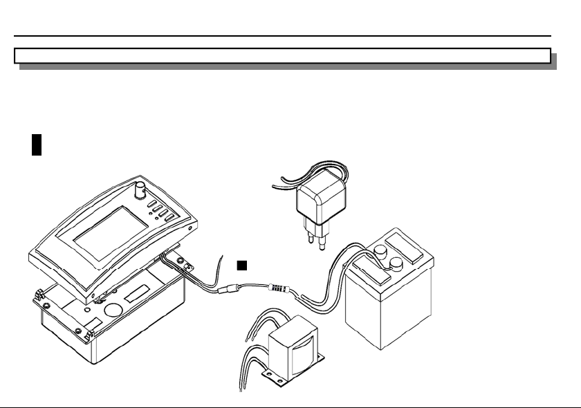
POWER SUPPLY
The VPS10 Panel Scope can be powered by means of an adapter, transformator or a battery.
Attention:
Use a non-regulated or regulated adapter of 9VDC that supplies a min. of 300mA.
For car use, mount a 315mA fuse and a 22ohm (1W) resisitor in series with each other and with the power supply.
To prevent damage to the panel scope, connect the input to the sound source through a 1/1 transformer.
Another possibility is to pick up the sound signal by means of a microphone that is connected to the input of the panel scope.
!
Type PS905 for 230V / PS905USA for
5
2
2
o
h
m
/
1
W
Fuseholder
Fig 1.0
Open chassis transformer 1.8VA (1 x 6V / 1 x 0.3A),
ordernr. 106001
Encapsulated transformer 1.8VA (1 x 6V / 1 x 0.3A),
ordernr. 1060018M
Car battery
Power supply
7
Page 8
Use
8
6
Fig 4.0
Fig 2.0
1
2
3
VPS10 Panel ScopeTM
USE
1
2
3
4
Fig 3.0
Fig 5.0
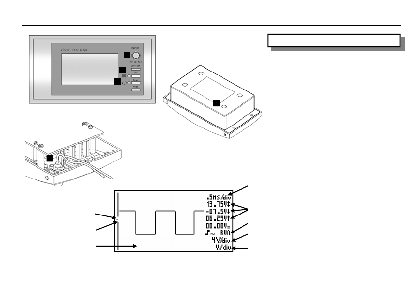
Survey of the connections and controls
1. BNC input connector (max. input 100Vp
AC+DC).
2. X10 probe testing signal
3. Reset
4. Serial number.
5. Power supply (pag. 7)
6. Internal input
Survey of the indications on the screen :
1. Dot indicates the vertical position of the
signal on the screen.
2. Trigger ope ning indication (fixed in the
middle of the screen)
3. Signal window with (possibly) the cross
4
5
6
or grid to indicate the various divisions.
4. Time per division
5. Measurement readout
6. Trigger information or screen hold
indication, input-coupling indication and
X10 probe setup.
7
7. Selected voltage per division.
8
8. Indication of the selected cursor key
function.
Page 9
VPS10 Panel ScopeTM
Fig 6.0
Use
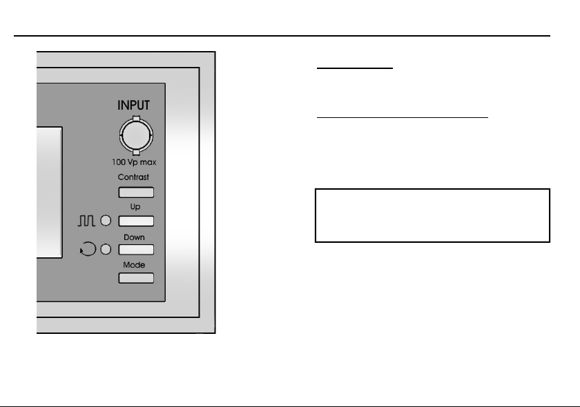
POWER ON/OFF
You can switch off the device by disconnecting it from the
power supply.
ADJUSTING THE CONTRAST (fig 6.0)
Keep pressing the ‘Contrast’-key to change the contrast.
Release the button at the desired setting.
The contrast adjustment direction is reversed each time
the button is pressed.
Remark:
To keep the contrast setting (also after a power cut),
keep the 'mode' button pressed until 'DEFAULT'
appears on the screen.
9
Page 10
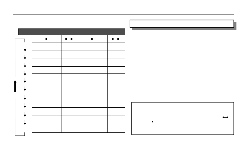
Key - instructions
Mode
V/div
Higher sensitivity Autorange Lower sensitivity Autorange
t/div
Slower Timebase Autorange Faster Timebase Autorange
Input
X-pos
Y-pos
Trigger
Display
Meter 1
Move upwards into
Meter 2
Meter 3
Meter 4
* Only when Power readout is selected !
Up Down
ac / dc GND x1 / x10 Probe
Right Fast right Left Fast left
up Fast up down Fast down
Norm / run /roll Slope
screenlayout Grid / crosshair
table
Higher load * Move downwards into
“ “ “ “
“ “ “ “
“ “ “
table
10
Lower load *
VPS10 Panel ScopeTM
KEY - INSTRUCTIONS
When the 'Mode', 'Up' or 'Down' buttons are not being used
during a few seconds, the device automatically returns to the
default mode.
Contrast: Use this button to set the desired contrast level.
Up: The 'UP‘ button is used to select the next value or pa-
rameter, depending on the selected 'mode' setting.
Down: The 'DOWN‘ button is used to select the previous
value or parameter, depending on the selected 'mode' setting.
Mode: This button is used to select the function of the 'UP'
and 'DOWN' buttons. Press the button repeatedly to cycle
through the functions.
NOTE:
Some keys have double function selected with a long
or short press.
Keeping the 'mode' button pressed for a long time will
save the current settings as default.
Page 11
VPS10 Panel ScopeTM
Input sensitivity
CHANGING THE INPUT SENSITIVITY
CHANGING THE INPUT SENSITIVITY (V/Div)
First press the „mode“ key Use up/down cursorkeys
Press the ‘MODE’ button repeatedly until the ‘V/div’ settings
for changing the input sensitivity (V/div) (Fig 5.0)
appear. Use up/down cursorkeys for changing the input
sensitivity (V/div)
1. Changing Volt/div:
The signal on the screen can be enlarge or reduce
The signal on the screen can be enlarged or reduced vertically
vertically by adjusting the displayed voltage per
by adjusting the displayed voltage per division. (V/div = voltage
division. (V/div = voltage per division).
per division).
Select the sensitivity : from 5mV to a maximum of 20V
Select the sensitivity : from 5mV to a maximum of 20V per
per division.
division.
50mV to 200V with X10 probe selection
50mV to 200V with X10 probe selection
Pressing the 'Up' key increases the input sensitivity (lower value
Pressing the 'Up' key increases the input sensitivity
for V/div).
(lower value for V/div).
Pressing the 'Down' cursor key decreases the input sensitivity
(higher value for V/div).
Pressing the 'Down' cursor key decreases the input
sensitivity (higher value for V/div).
Keeping the 'Up' or 'Down' button pressed for a long time
enables autorange.
Keeping the 'Up' or 'Down' button pressed for a long
time enables autorange.
Remark:
When autorange is enabled (t/div and v/div are highlighted),
it will be disabled as soon as the 'Up' or 'Down' button is
used into V/div, t/div or Y-pos - mode.
CHANGING THE TIMEBASE (t/Div)
Adjusting the time base will visualise more or fewer periods of a
signal (t/div = time per division). Set the time base between 1h
and 0.2µs per division.
Press the ‘MODE’ button repeatedly until the ‘t/div’ settings
appear.
Press the ‘up’ or ‘down’ cursor keys to increase or decrease the
timebase (time/div).
Note:
• Changing the timebase or sensitivity switches the
autorange mode immediately off. (Fig 8.0)
• At higher timebase (2us and faster) the scope uses
oversampling mode, only repetitive signals are correctly
displayed.
• Use the minimum time base (0.2 microsec) as a starting
point when measuring a signal and select longer time
bases until the signal is displayed properly. Otherwise the
display may not correctly reflect the signal under
measurement due to aliasing.
• Keeping the 'Up' or 'Down' button pressed for a long
time enables autorange.
• When autorange is enabled (time/div and V/div are
highlighted), it will be disabled as soon as the 'Up' of 'Down'
button is used.
11
Page 12
Auto-setup function
VPS10 Panel ScopeTM
12
Fig 7.0
Fig 8.0
AUTO-SETUP FUNCTION
The auto-setup function is ideally suited for quick
measurements as no manual setup has to be made
and everything is automatic. Use the auto-setup
function when the screen no longer displays a signal
after the manual setup.
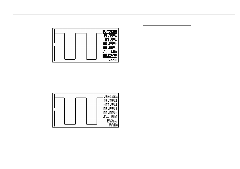
Autorange on (Fig. 7.0) :
Keeping the 'Up' or 'Down' button pressed for a long
time enables autorange (only in V/div or t/div mode!)
• Time/div and Volt/div settings are displayed inverted
• The time base and input sensitivity are automatically
set for optimal viewing of the input signal.
• Auto-triggering is set for time base 5µs/div or slower .
• Normal triggering is set for time base faster then 5µs/div.
• The slowest possible time base is 5ms/div.
• The fastest possible time base is 1µs/div
• Y-position is set to the center location.
Autorange off (Fig. 8.0) :
When autorange is enabled (time/div and V/div are
highlighted), it will be disabled as soon as the 'Up' of
'Down' button is used. (only in V/div, t/div or Y-pos.
mode!)
• Time/div and Volt/div settings are displayed in a
normal font (not highlighted).
Page 13
VPS10 Panel ScopeTM
Input
0
1
x
1
x
0
1
x
1
x
Fig 10
Fig 9.0
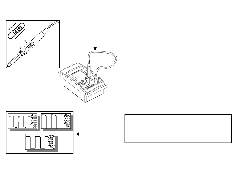
PROBE SETUP
Press the ‘MODE’ button repeatedly until the ‘INPUT’ settings
appear.
Press then the 'Down' button, it allows you to determine the
measuring probe setting as x1 or x10.
Setting up a X10 measuring probe
When used in the X10 position, a measuring probe should
always be calibrated to the measuring instrument being used,
in this case the Panel Scope. (Fig. 10)
• Set the probe input to X10
• Set the voltage per division to 1V
• Set the time per division to 0.1ms
• Select AC for the input.
Use the probe to perform measurements at the preselected
point on the front panel. Adjust the trimmer of the measuring
probe in order to obtain a square wave signal with a top that is
as flat as possible. (Fig. 11)
Notes:
• An ‘x10’ symbol is displayed if this mode has been selected.
• X10 measuring probes should be calibrated!
Fig 11
• IMPORTANT: Set the measuring probe in the x10 position for
measuring high voltages (>100Vp+dc)
13
Page 14
Input coupling / input reference
VPS10 Panel ScopeTM
14
Fig 12
Fig 13
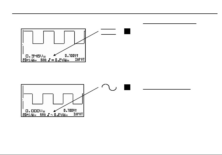
CHOICE OF INPUT COUPLING
1
2
Press the ‘MODE’ button repeatedly until the
‘INPUT’ settings appear.
A short activation of the 'Up' button will switch
between ac (2) or dc (1) input coupling.
When measuring the ”ripple” of a DC
voltage : put the input on AC to limit the
measurement to the AC component of the
signal.
Note:
• At time bases of 1s/div and slower, the
input coupling is DC-only.
SET THE INPUT REFERENCE
Keeping the 'Up' button pressed for a longer
time will internally connect the input to ground
and will keep the current readout as zero
reference for dc measurements.
Page 15
VPS10 Panel ScopeTM
Trigger gab
Fig 14
2 3
Fig 15
Signal screen
SIGNAL SCREEN
X - position mode :
1
Fig 16
Fig 17
Fig 18
Press the ‘MODE’ button repeatedly until the ‘X-pos’
setting appear.
• Operating the 'Up' button will move the screen to the right
• Operating the 'Down' button will move the screen to the left
Prolonged pressing will make the X-position change faster.
Notes:
A total of 256 samples are stored in memory, but the Xsize of the screen is limited. By shifting the X-direction
you can display all stored samples.
Y - position mode :
Press the ‘MODE’ button repeatedly until the ‘Y-pos’
setting appear.
• Operating the 'Up' button will move the displayed signal
upwards.
• Operating the 'Down' button will move the displayed
signal downwards
Prolonged pressing will make the Y- position change faster. A
small dot (3) in the left-hand corner of the screen will indicate
the direction in which the signal has moved (Y pos).
In this manner, the user will know in which direction the
signal was going when it went off-screen. (Fig 15).
15
Page 16

Trigger setup
VPS10 Panel ScopeTM
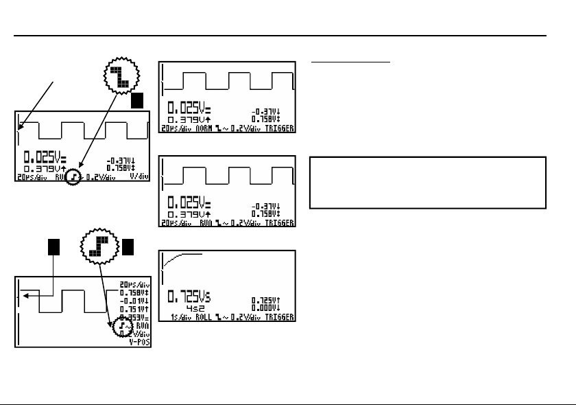
THE TRIGGER SETUP
Press the ‘MODE’ button repeatedly until the ‘trigger’ setting
appear.
• Use the ‘UP’ cursorkey to change the trigger-mode (norm,
run or roll).
Trigger modes :
”norm”= Normal trigger: A triggering (or manual trigger) must
occur before the sample memory is filled. Use this mode when
you want to start displaying the signal when it reaches a preset
threshold value. (Fig 16)
“run”= Auto-trigger mode, the scope automatically triggers if
no triggering occurs for a fixed period of time. This position is
used most frequently and should always be used for measuring
DC voltages in particular. (Fig 17)
“roll”= Roll-mode is available for timebases of 1s/div or slower.
Sampling is continuous and the screen starts rolling as soon as it is
full. Use this position for “recording” slow moving dc signals. (Fig 18)
Notes:
• At time base of 1s/div and slower, the input coupling is DC-only
• Normal triggering is the only triggermode for timebases of 2µs/div
or faster because of the oversampling method.
16
Trigger slope
Press the ‘DOWN’ cursorkey to set triggering at the rising or
falling edge of the input signal.
Triggering on the rising slope of the signal :
The screen will only display the signal when a positive slope is
"detected", viz. the signal has to rise in vertical direction in
order to trigger. (Fig 14)
Triggering on the falling slope of the signal:
The screen will only display the signal when a negative slope is
"detected", viz. the signal has to drop in vertical direction in
order to trigger. (Fig 15)
Notes:
Between triggering and the first sample-aquisition there is a
fixed hardware-determined delay. Because of this delay, the
sampled signal can show a different slope at fast timebases.
Page 17
VPS10 Panel ScopeTM
Display set-up
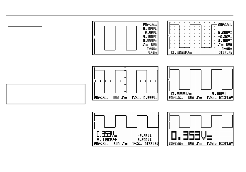
DISPLAY SET-UP
Press the ‘MODE’ button repeatedly until the
‘Display’ setting appear.
• The 'Up' button lets you choose between
6 different display layouts.
• The 'Down' button shows or hides the
grid or the co-ordinate system.
A grid divides the screen into reference
points. (Fig. 20)
A cross inserts a coordinate system into the
screen. (Fig. 21)
Notes:
The number of readout-digits depends on
the selected display layout.
Fig 19 Fig 20
Fig 21
Fig 22
Fig 23 Fig 24
17
Page 18
Readout set-up
VPS10 Panel ScopeTM
18
Fig 25
Fig 26
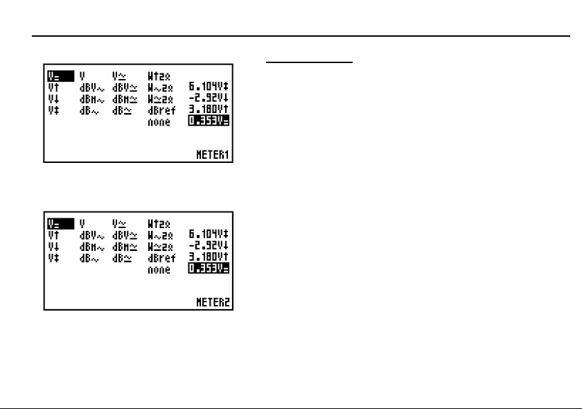
READOUT SET-UP
Press the ‘MODE’ button repeatedly until the desired meter setting
appears.
Depending on the selected display layout, 1 to 4 measurement results can
be displayed.
The meter mode displays a table with all possible measurement settings.
Select the desired setting with the 'Up' of 'Down' buttons.
Setting up the measurement readouts:
1. Press the MODE button repeatedly to select the first measurement
function ("METER 1").
2. Press the UP or DOWN button to select the parameter you want
METER 1 to measure (Fig 25).
3. Press the MODE button to select the second measurement function
("METER 2").
4. Press the UP or DOWN button to select the parameter you want
METER 2 to measure (Fig 26).
5. Press the MODE button to select the third measurement function
("METER 3").
6. Press the UP or DOWN button to select the parameter you want
METER 3 to measure.
7. Press the MODE button to select the fourth measurement function
("METER 4").
8. Press the UP or DOWN button to select the parameter you want
METER 4 to measure.
9. Press the ‘MODE’ button to return to the scope display
Page 19

VPS10 Panel ScopeTM
Readout set-up
1. DC voltage measurement (V=).
This function enables the user to measure DC voltages (only
for DC input coupling)
Useful tip for measuring DC voltages:
The readout can be set at zero (reference) for any position
(see ‘choice of input coupling‘, page 15) . Always use the
"run" trigger mode for DC voltage measurement
2. Maximum voltage (Vmax.).
The signal's positive peak voltage (difference between zero and
highest value) is displayed.
3. Minimum voltage (Vmin.).
The signal's negative peak voltage (difference between zero
and lowest value) is displayed.
4. Peak to peak (Vpp).
The signal's peak-to-peak voltage (difference between highest
and lowest value) is displayed.
5. True RMS readout (Vrms ac)
The area of the AC wave is calculated and converted to
voltage.
6. dBV measurement (dBV ac).
The measured signal (ac only) is converted to dBV (0dBV= 1V).
7. dBm measurement (dBm ac).
The measured signal (ac only) is converted to dBm
(0dBm= 0,775V).
8. dB measurement (dB ac).
The measured signal (ac only) is converted to dB (0dB= dBref*)
9. True RMS readout (Vrms ac+dc)
The area of the wave (+dc) is calculated and converted to
voltage.
10. dBV measurement (dBV ac+dc).
The measured signal (ac+dc) is converted to dBv (0dBV= 1V).
11. dBm measurement (dBm ac+dc).
The measured signal (ac + dc) is converted to dBm (0dBm=
0.775V).
12. dB measurement (dB ac+dc).
The measured signal (ac+dc) is converted to dB (0dB=dBref*)
*dB ref
The dB reference can be modified by selecting 'dBref' in the
settings table and closing the table by pressing the 'Mode'
button. The current value will then serve as 0 dB reference.
Audio power calculation.
The measured voltage is converted into power, supposing that the
voltage is measured across an impedance. The calculated power
can be displayed for loads of 2, 4, 8, 16 or 32 Ohm. The 2, 4, 8,
16 or 32 Ohm Charge for power readout can be modified by
keeping the 'Up' or 'Down' button pressed for a longer
time.
19
Page 20

Readout set-up
VPS10 Panel ScopeTM
20
6 5
1
2
3
4
9 10 13 14
8 7 12 11
Fig 28
15
13. W ac
AC rms power calculation into selected impedance
(most used).
14. W peak
Peak power calculation into selected impedance.
15. W ac+dc
AC+DC power calculation into selected impedance (a
normal audio signal can not have dc component).
Notes:
• If the signal goes off-screen or when the signal is too
small for measurement, the readout will show ???
(see fig 27)
• For all AC measurements: Make sure that at least
one or two periods are displayed or select the autosetup function.
• You can choose “none” to hide readouts.
Fig 27
• Depending on the selected screen layout one to four
different meter readouts can be displayed.
• Some readouts have more digits (accuracy) when
they are displayed on the left side of the screen
(change the screen layout, see “Display set-up”).
• For time bases of 1s/div and slower, the settings
cannot be changed and are fixed on: Vsample,
sample time, Vmin and Vmax. ‘Vs’ (Fig 28).
Page 21

®
PaneelOscilloscoop
Oscilloscope de Tableau
Einbau - Oszilloskop
Nederlands
Français
Deutsch
tm
tm
tm
Page 22

Inhoud / Sommaire / Inhaltsverzeichnis
VPS10 Panel ScopeTM
INHOUD
Algemeen................................................ 23
Kenmerken.............................................23
Opties.....................................................23
Veiligheid en waarschuwingen .......... 25
Voeding................................................... 27
Gebruik.................................................... 28
Aansluitingen en bedieningen................28
Aanduidingen op het scherm................. 28
Voeding AAN / UIT.................................30
Contrast instelling...................................30
Toetsfuncties .........................................32
Ingangsgevoeligheid (V/div)...................34
Tijdbasis (t/div).......................................36
Auto-setup instelling...............................38
Autobereik ingeschakeld.............38
Autobereik uitgeschakeld............38
Meetprobe instelling...............................40
Instellen van de ingangsgevoeligheid....42
Instellen van de ingangsreferentie......... 42
Signaal scherm ......................................44
X-positie functie...........................44
Y-positie functie...........................44
Trigger instelligen..................................46
Triggerfuncties.............................46
Triggerflank..................................48
Scherminstellingen ...............................51
Signaalvenster...................................... 52
Foutzoeken............................................. 58
Waarborg ............................................... 58
Technische gegevens .......................... 59
22
SOMMAIRE
Generalites..............................................23
Caractéristiques................................... 23
Options................................................. 23
Sécurité et mises en garde .................25
Alimentation ...........................................27
Utilisation ................................................29
Connections et commandes ................. 29
Aperçu des indications à l’écran ........... 29
Alimentation ‚marche / arrêt‘.................. 31
Réglage du contraste............................ 31
Instructions des boutons ...............33
Réglage dde la sensibilité d’entrée ....... 34
Modifier le temps de base..................... 36
Fonction de paramétrage automatique. 39
Allumer 'Autorange'.....................39
Eteindre 'Autorange'................... 39
Adaptation de la sonde de mesure ...... 41
Choix du couplage d’entrée.................. 43
Déterminer la réréfence d'entrée .......... 43
La fenêtre du signal............................... 45
Mode position X.......................... 45
Mode position Y.......................... 45
Réglage du déclenchement.................. 46
Fonctions de démarrage.............46
Flan de déclenchement.............. 47
Modes d’affichage ................................ 51
L’affichage de la mesure....................... 53
Localisation des erreurs ......................58
Garantie...................................................58
Données techniques .............................59
INHALTSVERZEICHNIS
Allgemein................................................ 24
Eigenschaften....................................24
zusatzmôglichkeiten..........................24
Sicherheit und warnungen ................. 25
Speisung................................................. 27
Gebrauch ................................................ 29
Bedienungselemente am Gerät ............29
Anzeigen auf dem Bildschirm ............... 29
Ein-/Ausschalten des Personal Scope.. 31
Einstellen des kontrasts.........................31
Tasten und Funktionen ........................33
Änderung der Eingansempfindlichkeit... 35
Zeitbasis ändern..................................... 37
'AUTO SETUP'-Funktion........................39
Autorange ein..............................39
Autorange aus
Messprobeanpassung ..........................41
Wahl des ingangssignals....................... 43
Einstellen der Eingangs-Refernz .......... 43
Des Signalfensters................................. 45
X-Position Modus........................45
Y-Position Modus........................45
Trigger-Einstellungen.............................47
Triggerfunktionen........................47
Flanken Einstellung.....................48
Bildschirm Einstellung............................51
Der MessAnzeige .................................. 53
Fechlersuche ......................................... 58
Garantie & Wartung ..............................58
Technische Kenndaten ........................59
........................ 39
Page 23

VPS10 Panel ScopeTM
Algemeen / Generalites
ALGEMEEN
Eigenschappen
• Hoog-contrast LCD met achtergrondverlichting.
• Volautomatische instelling voor volts/div en tijd/div.
• Recorderfunctie (roll mode) tot 25h per scherm.
• Trigger mode : run - normal - roll, slope -/+
• Piekmetingen : Max., Min. en Piek piek.
• AC metingen : rms, dB , dBV en dBm.
• AC+DC metingen : DC, rms, dB, dBV en dBm.
• Audio vermogen metingen in 2, 4, 8, 16 en 32Ώ :
rms vermogen, piekvermogen en AC+DC vermogen.
• X1 en X10 probe instelling.
• Verschillende beeldweergaven.
• X-pos en Y-pos verschuiving.
• AC/DC ingangskoppelingselectie.
• Nul instelfunctie voor DC en dB metingen.
Opties
• Adapter: Type PS905 (230V) / PS905USA (110V) (Fig 1. 0).
• Probe : gëisoleerd probe 60MHz (type probe60S)
• Transformator : * Ingegoten transformator 1.8VA
(1 x 6V / 1 x 0.3A), ordernr. 1060018M
* Open chassis transformator 1.8VA
(1 x 6V / 1 x 0.3A), ordernr. 106001
GENERALITES
Caractéristiques
• LCD haut contraste avec rétro éclairage.
• Fonction d’installation automatique pour v/div et t/div.
• Mode d’enregistrement ‘roll’, max. 25h par écran.
• Mode de déclenchement: run, normal, roll, slope -/+
• Mesures de crête: Max, min. et crête-à-crête.
• Mesures AC: rms, dB(relat.), dBV et dBm.
• Mesures AC+DC: DC, rms, dB, dBV et dBm.
• Mesures de puissance audio dans 2, 4, 8, 16 et 32Ώ: puissance
rms, puissance de crête et puissance AC+DC.
• Calibrage de sondes x1 et x10.
• Plusieurs modes d'affichage.
• Mode XY.
• Couplage d’entrée AC et DC.
• Ligne de zéro de référence pour DC et dB .
Options
• Adaptateur: Type PS905 (230V) / PS905USA (110V) (Fig 1. 0).
• Sonde : Sonde isolée 60MHz (type probe60S)
• Transformateur : * Transformateur moule 1.8VA
(1 x 6V / 1 x 0.3A), ordernr. 1060018M
* Transformateur châssis ouvert 1.8VA
(1 x 6V / 1 x 0.3A), ordernr. 106001
23
Page 24

Allgemein
ALLGEMEIN
Eigenschaften
• High contrast LCD mit hintergrundbeleuchtung.
• Auto Set-Up für volt/div und time/div.
• Aufnahme “Roll” Modus : bis 25st. Pro Schirm.
• Triggerart : run, normal, roll, slope -/+.
• Spitzenmessungen: Max, min. und Spitze-Spitze.
• AC-Messungen : rms, dB(relat.), dBV und dBm.
• AC/DC-Messungen : DC, rms, dB, dBV und dBm.
• Audio-Leistungsmessungen in 2, 4, 8, 16 und 32Ώ : rms-
Leistung, Spitzenleistung und AC/DC-Leistung.
• Kalibrierung der Sonden x1 und x10.
• Verschiedene Bildwiedergaben
• Modus X und Y.
• AC/DC-Eingangskupplung.
• Nullreferenzlinie für DC und dB.
Optional
• Adapter: Type PS905 (230V) / PS905USA (110V) (Fig 1.0).
• Probe : Isolierter tastkopf 60MHz (type probe60S)
• Transformator : * Printtransformator 1.8VA
(1 x 6V / 1 x 0.3A), ordernr. 1060018M
* Universaltransformator 1.8VA
(1 x 6V / 1 x 0.3A), ordernr. 106001
24
VPS10 Panel ScopeTM
Page 25

VPS10 Panel ScopeTM
Veiligheid en waarschuwingen / Securite et mises en garde / Sicherheit und warnungen
VEILIGHEID EN
WAARSCHUWINGEN
De paneeloscilloscoop is geschikt voor
het uitvoeren van metingen volgens de
IEC1010-1 norm met pollutie graad 1,
tot 600V aan categorie II. installaties.
Dit betekent dat men geen metingen
mag uitvoeren bij verontreinigde en/of
zeer vochtige lucht. Verder mag men
geen metingen uitvoeren aan geleiders
of installaties die spanningen voeren
hoger dan 600VRms boven het
aardpotentiaal. CAT II duidt op
conformiteit voor metingen aan huishoudelijke installaties.
De maximum ingangsspanning op de
klemmen van het toestel is 100Vp
(AC+DC).
Open de behuizing NIET als men
metingen aan het uitvoeren is.
Om elektrische schokken te vermijden,
moet men de testsnoeren verwijderen
alvorens de behuizing te openen.
Indien men metingen uitvoert aan
spanningen hoger dan 30V dan moet
men de bijgeleverde meetprobe met
geïsoleerde connector gebruiken.
(PROBE60S).
SECURITE ET MISES EN
GARDE
L‘oscilloscope de tableau convient pour
l'exécution de mesures suivant la
norme IEC1010-1 avec un degré de
pollution 1, jusqu'à 600V sur des
installations de catégorie II.
Cela signifie qu'aucune mesure ne
peut être effectuée dans une ambiance
polluée et/ou très humide. De même,
aucune mesure ne peut être effectuée
sur des conduits ou installations
soumis à des tensions supérieures à
600 Vrms au-dessus du potentiel de la
terre. CAT II indique la conformité pour
des mesures sur des installations
ménagères.
La tension d'entrée maximum aux
bornes de l'appareil est 100Vp (CA+CC)
N'ouvrez PAS le boîtier lorsque des
mesures sont en cours.
En vue d'éviter les chocs électriques, il
y a lieu de retirer les câbles de test
avant d'ouvrir le boîtier.
Si vous effectuez des mesures sous
des tensions supérieures à 30V, vous
devez utiliser une sonde de mesure
munie d'un connecteur isolé
(PROBE60S).
SICHERHEIT UND
WARNUNGEN
Der Einbau - Oszilloskop eignet sich
für die Durchführung von Messungen
entsprechend der Norm IEC1010-1 mit
Verschmutzungsgrad 1, bis 600V an
Kategorie II-Anlagen.
Das bedeutet, dass keine Messungen
durchgeführt werden dürfen bei
verschmutzter und/oder sehr feuchter
Luft. Ferner dürfen keine Messungen
erfolgen an Leitern oder Anlagen die
eine Spannung haben, die höher ist als
600Vrms über dem Erdpotential. CAT
II weist auf die Eignung für Messungen
an Haushaltsgeräten.
Die maximale Eingangsspannung an
den Klemmen des Geräts beträgt
100Vp (AC+DC)
Öffnen Sie das Gehäuse NICHT, wenn
Messungen durchgeführt werden.
Um Elektroschocks zu vermeiden,
müssen die Testschnüre entfernt
werden ehe das Gehäuse geöffnet wird.
Falls Messungen durchgeführt werden
bei Spannungen die höher sind als
30V, dann muss erst eine Messprobe
verwendet werden mit einem isolierten
Connector (PROBE60S).
25
Page 26

Voeding / Alimentation / Speisung
VPS10 Panel ScopeTM
Type PS905 (230V) / PS905USA (110V )
5
2
2
o
h
m
/
1
W
Autobatterij
Batterie de voiture
Autobatterie
Fig 1.0
26
Zekeringhouder
Porte-fusible
Sicherungshalter
Ordernr. FUSEJEF
Ingegoten transformator
Transformateur moule
Printtransformator
Open chassis transformator
Transformateur châssis
Universaltransformator
1.8VA (1 x 6V / 1 x 0.3A),
ordernr. 106001
1.8VA (1 x 6V / 1 x 0.3A),
ordernr. 1060018M
Page 27

VPS10 Panel ScopeTM
Power supply
VOEDING
De VPS10 paneeloscilloscoop kan
gevoed worden met behulp van een
adapter, een transformator of een
batterij.
Aandacht:
Gebruik een gestabiliseerde of
ongestabiliseerde adapter van 9VDC
(min. 300mA).
Voor gebruik in de wagen: monteer
een 315mA zekering en een 22ohm
weerstand in serie met elkaar en met
de voeding.
Om beschadiging van de
panelscoop te voorkomen moet de
!
ingang via een 1/1 transformator
met de geluidsbron verbonden
worden.
Een andere mogelijkheid is het
!
geluidsignaal op te pikken met een
microfoon die op de ingang van de
panelscoop aangesloten wordt.
ALIMENTATION
Le VPS10 peut être alimenté au moyen
d'un adaptateur, d'un transformateur ou
d'une batterie.
Attention:
Utilisez un adaptateur stabilisée ou
non stabilisé de 9VCC (min. 300mA)
Pour utilisation dans la voiture: montez
un fusible 315mA et une résistance
22ohm en série l'un avec l'autre et en
série avec l'alimentation.
Afin d'éviter des dommages à votre
oscilloscope, connectez l'entrée à
la source sonore via un transfor-
!
mateur 1/1.
Une autre possibilité est de capter
le signal sonore avec un microphone connecté à l'entrée de l'os-
!
cilloscope.
POWER SUPPLY
Das VPS10 Einbau - Oszilloskop kann
über ein Netzgerät, einen Transformator
oder eine Batterie versorgt werden.
Attention:
Verwenden Sie ein stabilisiertes oder
nicht-stabilisiertes Netzgerät von
9VDC mit mindestens 300mA.
Zur Anwendung im Wagen,
verbinden Sie eine Sicherung von
315mA und einen Widerstand von 22
Ohm (1W) miteinander und mit der
Spannungs-versorgung in
Reihenschaltung.
Um Beschädigung des
Oszilloskops zu vermeiden muss
!
der Eingang über einen 1/1
Transformator mit einer Tonquelle
verbunden werden.
Eine andere Möglichkeit ist: Das
!
Tonsignal mit einem Mikrofon,
das an den Eingang des
Oszilloskops angeschlossen ist,
empfangen.
27
Page 28

Gebruik / Utilisation / Gebrauch
Fig 2.0
6
Fig 4.0
1
2
3
28
VPS10 Panel ScopeTM
GEBRUIK
1
2
3
4
Fig 3.0
Fig 5.0
Overzicht van de aansluitingen en
bedieningen op het toestel
1. BNC ingangsconnector (max. input 100Vp
AC+DC).
2. X10 probe testsignaal
3. Reset
4. Serienummer.
5. voedingsaansluiting (pag. 26)
6. Intern ingangssignaal
Overzicht van de aanduidingen op het scherm :
1. Stip ter indicatie van de verticale positie van
het signaal op het scherm.
2. Triggeropeningindicatie (vast in het midden
van het scherm).
3. Signaalvenster met eventueel aanwezige
4
5
6
assenkruis of raster aanduiding.
4. De tijd per divisie.
5. Meter uitlezing .
6. Triggerinformatie of weergave van de ‘hold‘
functie, ingangskoppelingindicatie en X10
probe instelling.
7
7. Spanning per divisie.
8. Aanduiding van de gekozen functie voor de
8
cursortoetsen.
Page 29

VPS10 Panel ScopeTM
Gebruik / Utilisation / Gebrauch
UTILISATION
Aperçu des connexions et comma nde s s ur l'appareil
1. Connecteur d'entrée BNC (maximum 100Vp CA+CC).
2. Signal de test pour sonde X10.
3. Reset.
4. Numéro de série.
5. Alimentation (page. 26).
6. Signal d'entrée interne
Aperçu des indications à l'écran :
1. Point indiquant la position verticale du signal à l'écran.
2. Indication du niveau de démarrage (fixe au milieu de
l'écran)
3. Fenêtre du signal avec indication (éventuelle) axes
perpendiculaires ou de la grille par division.
4. Le temps par division.
5. Affichage.
6. Information de démarrage ou indication d'arrêt sur image
(Hold), indication de couplage à l'entrée et sonde X10
7. La tension instaurée par division
8. Indication de la fonction choisie (touches curseur).
GEBRAUCH
Übersicht der Anschlüsse und Bedienungs-elemente am Gerät
1. BNC-Eingangsconnector (max. 100Vp AC+DC).
2. X10-Taster-Testsignal.
3. Reset.
4. Serien nr.
5. Speisung (Seite 26).
6. Internes Eingangssignal
Übersicht der Anzeigen auf dem Bildschirm :
1. Punkt Andeutung der senkrechten Position des Signals.
2. Triggeröffnungsanzeige Fest in der Mitte des
Bildschirms.
3. Signalfenster Mit eventuell Achsenkreuz- oder
RasterAnzeige.
4. Die Zeit pro Verteilung oder Zeit zwischen den
Markierungen (falls vorhanden)
5. MesserAnzeige
6. Triggerinformationen oder Bildschirm fixiert Anzeige,
eingangskopplungs-anzeige und X10-Tastereinstellung.
7. Die eingestellte Spannung pro Verteilung.
8. Anzeige der gewählten Funktion (Cursor Tasten).
29
Page 30

Gebruik / Utilisation / Gebrauch
30
Fig 6.0
VPS10 Panel ScopeTM
IN / UITSCHAKELEN
U kunt het toestel uitschakelen door het los te koppelen van de
voeding.
CONTRASTINSTELLING (fig 6.0)
De toets ‘Contrast’ ingedrukt houden tot het gewenste contrast
van het scherm bereikt is.
De richting van het contrast keert om telkens als u de toets
indrukt.
Opmerking:
Om de contrastinstelling te behouden (ook na spanningsuitval)
dient u de 'mode'-toets ingedrukt te houden totdat 'DEFAULT'
op het scherm verschijnt.
Page 31

VPS10 Panel ScopeTM
Gebruik / Utilisation / Gebrauch
FONCTION MARCHE / ARRÊT
Vous pouvez éteindre l'appareil en le débranchant de l'alimentation.
REGLAGE DU CONTRAST (fig 6.0)
Enfoncez ce bouton ‘Contrast’ jusqu'à ce que le contraste de
l'écran vous convient.
La direction de réglage du contraste est inversée chaque fois
que le bouton est enfoncé.
Remarque:
Pour sauvegarder le réglage du contraste (même après une
coupure de courant), enfoncez le bouton 'mode' jusqu'à ce que
'DEFAULT' apparaît sur l'écran.
EIN / AUS SCHALTEN
Sie können das Gerat ausschalten, indem Sie es von der
Spannungsversorgung trennen.
ADJUSTING THE CONTRAST (fig 6.0)
Diese ‘Contrast‘Taste eingedrückt halten, bis der gewünschte
Schirmkontrast erreicht ist.
Wenn Sie die Kontrast-Taste lange eindrücken, ändert sich der
Kontrast. Wenn Sie die Taste loslassen und nochmals eindrücken,
ändert sich der Kontrast erneut aber in umgekehrter Richtung.
Anmerkungen :
Um die Kontrasteinstellung zu speichern (auch nach einem
Spannungsausfall) müssen Sie die 'mode'-Taste eingedrückt
halten bis 'DEFAULT' auf dem Schirm erscheint.
31
Page 32

Toetsfunctie‘s / Instructions des boutons / Tastenfunktionen
Mode
V/div
t/div
Slower Timebase Autorange Faster Timebase Autorange
Input
X-pos
Y-pos
Trigger
Display
Meter 1
Move upwards into
Meter 2
Meter 3
Meter 4
* Only when Power readout is selected !
Up Down
Higher sensitivity Autorange Lower sensitivity Autorange
ac / dc GND x1 / x10 Probe
Right Fast right Left Fast left
up Fast up down Fast down
Norm / run /roll Slope
screenlayout Grid / crosshair
readable table
“ “ “ “
“ “ “ “
“ “ “
Higher load * Move downwards into
readable table
32
Lower load *
VPS10 Panel ScopeTM
TOETSFUNCTIES
Worden de 'Mode”, “Up” of “Down” toetsen gedurende enkele
seconden niet meer bediend, dan wordt automatisch
teruggekeerd naar de default mode.
Contrast : Deze toets dient om het gewenste contrast in te
stellen.
Up : Met de toets “UP“ kan men de volgende waarde of
parameter kiezen afhankelijk van de gekozen “mode“instelling.
Down : Met de toets “DOWN“ kan men de vorige waarde of
parameter kiezen afhankelijk van de gekozen “mode“instelling.
Mode : Met deze toets kan men door herhaaldelijk drukken de
functie van de “up / down“ - toetsen kiezen volgens de cyclus.
OPMERKING:
Sommige toetsen hebben een dubbele functie,
selecteerbaar via lange of korte bediening.
Bij de meeste selecties zal de scoop terugkeren naar de
standaardinstelling indien gedurende 7sec. geen enkele toets
ingedrukt werd waardoor de selectie geannuleerd wordt.
Lang ingedrukt houden van de “mode”-toets zal de huidige
instellingen als default bewaren.
Page 33

VPS10 Panel ScopeTM
INSTRUCTIONS DES BOUTONS TASTENFUNKTIONEN
Si les boutons "Mode", "Up" ou "Down" ne sont pas utilisés
pendant quelques secondes, l'appareil retournera automatiquement au mode standard.
Contrast: Ce bouton sert à régler le niveau du contraste.
Up: Le bouton "UP" vous permet de choisir la valeur ou le
paramètre suivant en fonction du réglage 'mode' sélectionné.
Down: Le bouton 'DOWN' vous permet de choisir la valeur ou le
paramètre précédant en fonction du réglage 'mode' sélectionné.
Mode: Ce bouton sert à déterminer la fonction des boutons "UP"
et "DOWN". Pressez le bouton à plusieurs reprises pour parcourir le cycle.
Toetsfunctie‘s / Instructions des boutons / Tastenfunktionen
Wenn die "Mode", "Up" oder "Down"-Tasten einige Sekunden
nicht verwendet werden, dann wird automatisch auf
Standardmodus zurückgeschaltet.
Kontrast : Taste zum Einstellen des Kontrasts.
Up: Mit der "aufwärts"-Taste "UP" können Sie den nächsten Wert
oder Parameter wählen, abhängig von der gewählten ModusEinstellung.
Down: Mit der "abwärts"-Taste "DOWN" können Sie den vorigen
Wert oder Parameter wählen, abhängig von der gewählten ModusEinstellung.
Mode: (Modus) Wenn Sie diese Taste wiederholt drücken können
Sie die Funktion der "up / down" –Tasten nach folgendem Zyklus
REMARQUE :
Certaines touches ont une double fonction, selon qu’on
exerce une brève pression ou que l’on maintient la
pression quelques instants
Dans la plupart des cas, l'appareil retourne automatiquement
au mode par défaut, si aucune touche du clavier n'a été
enfoncée pendant plus de 7 sec. Toute sélection en cours
sera annulée.
Enfoncer le bouton "mode" pendant un certain temps sauve-
gardera les réglages actuels comme réglages standard.
ANMERKUNGEN :
Einige Tasten haben eine Doppelfunktion, die durch langes
und kurzes drücken unterschieden wird..
Das Einstellen der meisten Funktionen wird nach 7 sek.
Abgebrochen, wenn keine Taste gedrückt wird. Das Gerät
zeigt dann die Hauptanzeige.
Wenn Sie die "mode"-Taste lange eingedrückt halten,
werden die jetzigen Einstellungen als Standardeinstellung
gespeichert werden.
33
Page 34

Ingangsgevoeligheid / Sensibilitié d‘entrée / Eingangsempfindlichkeit
VPS10 Panel ScopeTM
WIJZIGEN VAN INGANGSGEVOELIGHEID (V/Div)
Druk herhaaldelijk op de ‘MODE’-toets tot men de instelling‘v/div’
bereikt heeft. Gebruik de 'Up' of 'Down'-toets voor het wijzigen van
de ingangsgevoeligheid (V/div).
Het signaal op het scherm vergroten of verkleinen in verticale
richting kan door de getoonde spanning per verdeling aan te
passen (V/div = spanning per verdeling).
Selecteer de gevoeligheid van 5mV tot 20V maximum per
verdeling.
50mV tot 200V / verdeling met X10 probe-instelling.
Bediening van de 'Up' - toets zal de ingangsgevoeligheid
verhogen.
Bediening van de 'Down'- toets zal de ingangsgevoeligheid
verminderen.
Lang ingedrukt houden van de 'Up' of 'Down'-toets schakelt het
autobereik in.
Opmerking:
Indien autobereik aan staat (t/div en v/div worden invers
weergegeven) zal deze uitgeschakeld worden zodra de 'Up' of
'Down'-toets bediend wordt in de v/div, t/div of in de Y-pos. mode.
34
REGLAGE DE LA SENSIBILITE D'ENTREE (V/Div)
Pressez le bouton ‘MODE’ à plusieurs reprises jusqu'à ce que
les réglages ‘V/div’ apparaissent. Utilisez le bouton 'Up' ou
'Down' pour modifier la sensibilité d'entrée (V/div).
Le signal à l'écran peut être agrandi ou diminué dans le sens
vertical en adaptant la tension affichée par division (V/div =
tension par division).
Choisissez la sensibilité : de 5mV à un maximum de 20V par
division.
50mV à 200V/div avec sonde X10
Presser le bouton 'Up' augmentera la sensibilité d'entrée.
Presser le bouton 'Down' réduira la sensibilité d'entrée.
Enfoncez le bouton 'Up' ou 'Down' pendant un certain temps
pour activer la sélection de portée automatique.
Remarque:
Quand la sélection de paramétrage automatique est activée
(t/div et v/div mis en inverse), elle sera désactivée quand le
bouton 'Up' ou 'Down' est utilisé en mode v/div, t/div ou
position Y.
Page 35

VPS10 Panel ScopeTM
ÄNDERUNG DER EINGANGSEMPFINDLICHKEIT (v/div) :
Drücken Sie wiederholt die ‘MODE’-Taste bis die ‘V/div’-
Einstellungen erscheinen. Drücken Sie die Pfeiltasten 'Up' und
‘Down' um die Eingangsempfindlichkeit (V/div) zu ändern.
Das Signal kann in senkrechter Richtung auf dem Bildschirm
vergrößert oder verkleinert werden, indem die gezeigte Spannung
pro Verteilung angepasst wird (V/div = Spannung pro Verteilung).
Wählen Sie die Empfindlichkeit: von 5mV bis zu maximal 20V pro
Teilung.
50mV bis 200V/div in X10
Bedienung der 'Up'-Taste wird die Eingangsempfindlichkeit
erhöhen.
Bedienung der 'Down'-Taste wird die Eingangsempfindlichkeit
senken.
Wenn Sie die 'Up' oder 'Down' Taste lang eingedrückt halten,
schaltet die automatische Bereichswahl automatisch ein.
Anmerkungen :
Wenn die automatische Bereichswahl eingeschaltet ist, wird diese
(Zeit/Div und V/Div werden invers angezeigt) ausgeschaltet
werden, sobald die 'Up' oder 'Down'-Tasten benutzt werden im
Modus v/div, t/div oder Position Y.
Ingangsgevoeligheid / Sensibilitié d‘entrée / Eingangsempfindlichkeit
35
Page 36

Tijdbasis / Base de temps / Zeitbasis
VPS10 Panel ScopeTM
WIJZIGEN VAN DE TIJDBASIS (t/Div)
Meer of mindere perioden van een signaal zichtbaar maken door
de tijdbasis aan te passen (t/div = tijd per verdeling). Stel de
tijdbasis tussen 1h en 0,2µs per verdeling.
Druk herhaaldelijk op de ‘MODE’-toets tot men de instelling ‘t/div’
bereikt heeft.
Druk de ‘UP‘ of ‘DOWN‘-toets voor het wijzigen van de tijdbasis (t/div).
Opmerking:
• Het wijzigen van de tijdbasis of gevoeligheid schakelt het
autobereik uit. (Fig 7.0)
• Bij grotere tijdbasissen (2µs en sneller) zal de scoop de
overbemonsteringinstelling gebruiken, enkel herhalende
signalen worden juist weergegeven.
• Begin voor het meten van periodieke signalen op een zo
klein mogelijke tijdbasis (0.2µs) en vergroot tot de uitlezing
correct is. Bij een niet correcte instelling kan het gebeuren
dat de periode van het getoonde signaal niet correct is, dat
komt door de interferentie (aliasing) van het binnenkomend
signaal met de bemonsteringsfrekwentie.
• Lang ingedrukt houden van de 'Up' of 'Down' toets
schakelt het autobereik in.
• Indien autobereik aan staat (tijd/div en V/div worden invers
weergegeven) zal deze uitgeschakeld worden zodra de
'Up' of 'Down' toets bediend wordt.
36
REGLAGE DE LA BASE TEMPS (t/Div)
Quand vous modifiez la base de temps, plus ou moins de
périodes seront visibles sur l‘ecran (t/div = temps par division).
Réglez la base de temps entre 1h et 0,2µs par division.
Pressez le bouton ‘MODE’ à plusieurs reprises jusqu'à ce que
les réglages ‘t/div’ apparaissent.
Utilisez le bouton 'Up' ou 'Down' pour modifier la base de
temps (V/div).
Remarque :
• Tout changement de la vitesse de balayage ou de la sensibilité,
annule le mode "autorange". (Fig 7.0)
• Aux vitesses de balayage supérieures ou égales à 2µs,
l'oscilloscope travaille en mode de sur-échantillonnage. Seuls les
signaux périodiques (répétitifs) peuvent être affichés correctement.
• Lors de la mesure d'un signal, commencez par utilisez la vitesse
de balayage la plus rapide (0.2 µs) et puis diminuez
progressivement cette vitesse jusqu'à ce que le signal soit bien
visible. Autrement, l'affichage peut ne pas correctement refléter le
signal mesuré. Ce phénomène "d'aliasing" est une interférence
entre le signal et la fréquence d'échantillonnage qui est
insuffisamment rapide.
• Enfoncez le bouton 'Up' ou 'Down' pendant un certain temps
pour activer la sélection de portée automatique.
• Quand la sélection de portée automatique est activée (temps/div et
V/div mis en inverse), elle sera désactivée quand le bouton 'Up' ou
'Down' est utilisé.
Page 37

VPS10 Panel ScopeTM
ÂNDERN DER ZEITBASIS (t/Div)
Wenn zie die Zeitbasis ändern, werden mehr oder weiniger
Perioden auf demSchirm erscheinen. (t/div = Zeit pro Verteilung).
Stellen Sie die Zeitbasis zwischen 1h und 0,2µs pro Divisionen ein.
Drücken Sie wiederholt die ‘MODE’-Taste bis die ‘t/div’-
Einstellungen erscheinen.
Drücken Sie die tasten 'Up' ou 'Down' um die Zeitbasis (t/div)
zu ändern.
Anmerkungen :
• Das Ändern der Zeitbasis oder der Eingangsempfindlichkeit
beendet sofort den Autorange Modus. (Abb. 37)
• Bei höheren Zeitbasen (2µs und schneller) wechselt das
Gerät in den Oversampel Modus. Es werden nur sich
wiederholende Signale richtig dargestellt.
• Beginnen Sie mit dem Messen von periodischen Signalen auf
einer höchstmöglichen Zeitbasis (2µs) und verringern Sie
dann, bis die Anzeige stimmt. Bei nicht richtiger Einstellung
kann es passieren, dass die Periode des gezeigten Signals
nicht richtig ist. Das liegt an der Interferenz (aliasing) des
eingehenden Signals mit der Abtastfrequenz.
• Wenn Sie die 'Up' oder 'Down'-Taste lang drücken,
schaltet die automatische Bere ichsw ahl ei n.
• Wenn die automatische Bereichswahl eingeschaltet ist (Zeit/
Div und V/Div werden invers angezeigt), wird diese
ausgeschaltet werden, sobald eine 'Up' oder 'Down'
verwendet wird.
Tijdbasis / Base de temps / Zeitbasis
37
Page 38

Auto setup / Paramétrage automatique /’Auto setup’ Funktion
VPS10 Panel ScopeTM
38
Fig 7.0
Fig 8.0
'AUTO SETUP' INSTELLING
De auto setup functie is ideaal om snel een meting uit te
voeren, men hoeft geen enkele manuele instelling te doen,
alles gebeurt automatisch. Gebruik de auto setup functie
als men na het manueel instellen geen signaal meer op het
scherm ziet.
Autobereik aan (Fig. 7.0) :
Lang ingedrukt houden van de 'Up' of 'Down'-toets
schakelt het autobereik in. (Enkel bij v/div of t/div !)
• tdiv en v/div instelling zijn invers gemarkeerd.
• De tijdbasis en ingangsgevoeligheid zijn automatisch
• Auto-triggering is ingesteld voor een tijdbasis van 5µs/div en
• Normale triggering is ingesteld voor een tijdbasis sneller
ingesteld voor een optimale weergave van het signaal.
trager.
dan 5µs/div.
• De traagst mogelijke tijdbasis is 5ms/div.
• De snelst mogelijke tijdbasis is 1µs/div.
• Y-positie wordt in het midden van het scherm geplaatst.
Autobereik uit (Fig. 8.0) :
Als 'autorange' ingeschakeld is (time/div en V/div zijn
invers), zal dit uitgeschakeld worden zodra de toets 'Up' of
'Down' wordt gebruikt. (enkel in V/div, T/div of Y-pos.
mode!)
• Time/div en Volt/div uitlezing zijn normaal weergegeven
(niet invers).
Page 39

VPS10 Panel ScopeTM
Auto setup / Paramétrage automatique /’Auto setup’ Funktion
FONCTION DE PARAMÉTRAGE AUTOMATIQUE
La fonction de paramétrage automatique est idéale pour
effectuer rapidement une mesure, vous ne devez procéder à
aucun réglage manuel, tout est automatique. Utilisez la fonction
de paramétrage automatique si aucun signal n'apparaît à
l'écran après un réglage manuel.
Autorange actif (Fig. 8.0) :
Keeping the 'Up' or 'Down' button pressed for a long time
enables autorange (uniquement en mode v/div ou t/div!)
• Les valeurs de t/div et de v/div sont affichées en vidéo inversée.
• La base de temps et la sensibilité d'entrée sont ajustées
automatiquement pour une visualisation optimale du signal
d'entrée.
• La synchronisation est automatique pour les vitesses de
balayage de 5us/div ou moindres.
• Le mode de synchronisation est normal pour les vitesses de
balayages supérieures à 5µs/div.
• La vitesse de balayage la plus lente est de 5ms/div.
• La base de temps la plus rapide est de 1µs/div.
• La trace est recentrée verticalement (Y) au centre de l'écran.
Autorange inactif (Fig. 8.0) :
Quand 'autorange' est allumé (time/div et V/div sont mises en
évidence), il sera éteint du moment que le bouton 'Up' ou
'Down' est utilisé. (uniquement en mode V/div, T/div ou Y-pos.!)
• Les valeurs de Time/div et de Volt/div sont affichées
normalement. (pas d'inversion vidéo).
'AUTO SETUP'-FUNKTION
Die 'Auto-setup'-Funktion ist ideal für die schnelle Durchführung
einer Messung. Sie brauchen nichts manuell einzustellen, alles
läuft automatisch.. Verwenden Sie die 'Auto setup'-Funktion,
wenn Sie nach dem manuellen Einstellen kein Signal mehr auf
dem Bildschirm sehen.
Automatische Bereichseinstellung „Ein“ (Abb. 8.0) :
Wenn Sie die 'Up' oder 'Down'-Taste lang drücken, schaltet
die automatische Bereichswahl ein. (nur in v/div oder t/div
modus!)
• t/div und v/div Einstellung wird invertiert dargestellt.
• Die Zeiteinstellung und Eingangsempfindlichkeit werden
automatisch auf den optimalen Wert zu dem Eingangssignal
gesetzt.
• Auto-Trigger wird bei einer Zeitbasis 5µs/div oder weniger
gesetzt.
• Trigger ist bei einer Zeitbasis von mehr als 5µs/div gesetzt.
• Die kleinst mögliche Zeitbasis ist 5ms/div.
• die schnelstmögliche Zeitbasis ist 1µs/div
• Die Nulllinie ist in der Mitte zentriert.
Automatische Bereichseinstellung (Abb. 8.0) :
Wenn die automatische Bereichswahl aktiviert ist, (time/div und
V/div werden markiert), wird sie ausgeschaltet werden, sobald
die aufwärts oder abwärts-Tasten verwendet werden. (nur in V/
div, T/div oder Y-pos. Modus!)
• t/div und v/div Einstellung wird nicht invertiert dargestellt.
39
Page 40

Meetprobe / Sonde mesure / Messprobe
VPS10 Panel ScopeTM
40
0
1
x
1
x
0
1
x
1
x
Fig 10
Fig 9.0
PROBE SETUP
Druk herhaaldelijk op de ‘MODE’-toets tot men de instelling
‘INPUT’ bereikt heeft.
Met de 'Down'-toets kiest men de meetprobe-instelling x1 of x10.
Afregelen van een x10 meetprobe
Bij gebruik van de x10 stand moet de meetprobe altijd
gekalibreerd zijn op het te gebruiken meettoestel, in dit geval
de paneeloscilloscoop. (Fig. 9.0)
• Stel de probe en de ingang in op X10
• Stel de volts per divisie in op 1V
• Stel de tijd per divisie in op 0,2ms.
• Kies AC voor ingangskeuze.
Meet met de probe op het daarvoor voorziene punt op het
voorpaneel. Regel de trimcondensator van de meetprobe tot
men een zo vlak mogelijke top van de blokgolfspanning
bekomt. (Fig. 10).
Fig 11
Opmerkingen :
• Rekent automatisch de uitlezing om, afhankelijk van de x1 of
x10 instelling van de probe.
• Het symbool ‘x10’ wordt weergegeven bij selectie van deze
instelling.
• X10 meetprobes moeten gekalibreerd worden!
• BELANGRIJK : Voor het meten van hoge spanningen plaats
de meetprobe in de x10 stand.(>100Vp+dc)
Page 41

VPS10 Panel ScopeTM
Meetprobe / Sonde mesure / Messprobe
REGLAGE DE LA SONDE
Pressez le bouton ‘MODE’ à plusieurs reprises jusqu'à ce que
les réglages ‘INPUT’ apparaissent.
Le bouton 'Down' vous permet de déterminer le réglage de la sonde
de mesurage comme x1 ou x10.
Réglage d'une sonde de mesure X10
Il est toujours nécessaire de régler une sonde de mesure en
position X10 sur l'appareil de mesure à utiliser, en l'occurrence
le Personal Scope. (Fig. 9.0)
• Réglez l'entrée de la sonde sur X10
• Réglez les volts par division sur 1V
• Réglez le temps par division sur 0.2ms
• Sélectionnez le choix d'entrée CA .
Effectuez un mesurage en mettant la sonde sur le point prévu à cet
effect sur le panneau frontal. Réglez le condensateur trim de la
sonde de mesure jusqu'à l'obtention d'une tension d'onde carrée
ayant un sommet le plus plat possible (Fig. 10)
Remarques :
• Le but est de calculer automatiquement l'affichage des
mesures, que la sonde se trouve en position x1 ou x10.
• Un symbole 'x10' s'affiche si ce mode est sélectionné.
• Les sondes de mesure X10 doivent être calibrées! Voir ci-dessous.
• IMPORTANT: Pour la mesure de tensions élevées
(supérieures à 100Vp + CC), placez la sonde de mesure
appropriée en position X10.
TASTKOPF EINSTELLUNG
Drücken Sie wiederholt die ‘MODE’-Taste bis die ‘INPUT’-
Einstellungen erscheinen.
Mit der 'Down'-Taste können Sie die Einstellung der Messsonde
auf x1 oder x10 einstellen.
Feinabstimmung einer X10-Messprobe
Es ist noch immer notwendig, um eine Messprobe im X10-Stand
auf das zu verwendende Messgerät einzustellen, in diesem Fall
PersonalScope. (Abb. 9.0)
• Stellen Sie den Tastereingang auf X10 ein
• Schalten Sie den Tastkopf auf X10
• Stellen Sie die Volteinheiten pro Division ein auf 1V
• Stellen Sie die Zeit pro Division ein auf 0.2ms
• Wählen Sie AC als Eingangs.
Messen Sie mit dem Taster an der dazu vorgesehenen Stelle
unter den Batteriedeckel. Regeln Sie den Trimmerkondensator
der Messprobe bis die Spitze der Blockwellenspannung so flach
wie möglich ist. (Abb. 10)
Anmarkungen :
• Berechnet automatisch die Messwerte für X1 oder X10 Tastköpfe
• Ein X10 Symbol wird angezeigt, wenn der Modus eingestellt ist.
• Der Tastkopf sollte vor der Messung Kalibriert werden. Siehe
weiter unten.
• WICHTIG: Bringen Sie für das Messen hoher Spannungen (mehr
als 100Vp + DC) die dafür geeignete Messprobe in den X10-Stand.
41
Page 42

Input / Entree / Eingang
42
Fig 12
Fig 13
VPS10 Panel ScopeTM
KEUZE VAN DE INGANGSKOPPELING
Druk herhaaldelijk op de ‘MODE’-toets tot men
1
de instelling ‘INPUT’ bereikt heeft.
Kort bedienen van de 'Up'-toets wisselt tussen
ac (2) of dc (1) ingangskoppeling.
Wil men bijvoorbeeld de “rimpel” op een
gelijkspanning meten, dan kan men best de
ingang op AC zettten en meet men enkel
het wisselspanningscomponent van het
signaal.
Opmerking :
• Bij een tijdbasis van 1s/div en trager is de
ingangskoppeling enkel DC.
2
INSTELLEN VAN DE INGANGSREFERENTIE
Lang ingedrukt houden van de 'Up'-toets
schakelt de ingang intern aan de massa en
bewaart de huidige uitlezing als nulreferentie
voor de dc metingen.
Page 43

VPS10 Panel ScopeTM
Input / Entree / Eingang
CHOIX DU COUPLAGE D'ENTREE
Pressez le bouton ‘MODE’ à plusieurs reprises jusqu'à ce que
les réglages ‘INPUT’
Presser le bouton 'Up' brièvement commutera entre couplage
d'entrée CA (2) et CC (1).
Si vous souhaitez par exemple mesurer le "ondulation
résiduelle" sur une tension continue, réglez l'entrée sur CA
pour ne mesurer que la composante courant alternatif du
signal.
Remarque :
• Aux vitesses de balayage de 1s/div ou moindres, seul le
couplage en continu (DC) est possible.
VERROUILLAGE DE LA TENSION DE REFERENCE EN
ENTREÉ
Presser le bouton 'Up' pendant un certain temps établira une
connexion interne de l'entrée à la masse et instaura la valeur
de mesurage actuelle comme référence zéro pour les mesurages cc.
WAHL DES INGANGSSIGNALS
Drücken Sie wiederholt die ‘MODE’-Taste bis die ‘INPUT’-
Einstellungen erscheinen.
Ein kurzer Tastendruck auf 'Up' wechselt zwischen AC (2) -
oder DC (1)- Eingang.
Soll zum Beispiel die “Restwelligkeit” des Gleichspannung
gemessen werden, dann wird der Eingang am besten auf
AC eingestellt, denn dann wird ausschließlich die
Wechselspannungs-komponente des Signals gemessen.
Anmerkung :
• Ab einer Zeiteinheit von 1s/div oder weniger gibt es nur die
Einstellung DC
EINSTELLEN DER EINGANGS-REFERENZ
Ein langer Tastendruck der 'Up'-Taste schaltet den Eingang
intern auf Masse und speichert den jetzigen Wert als
Nullreferenz für die DC-Messungen.
43
Page 44

Signaalvenster / Affichage du signal / Signal Bildschirm
Trigger gab
1
Fig 14
2 3
Fig 15
44
Fig 16
Fig 17
Fig 18
VPS10 Panel ScopeTM
SIGNAALVENSTER
X - positie :
Druk herhaaldelijk op de ‘MODE’- toets tot men de instelling
‘X-POS’ bereikt heeft.
• Met de 'Up'-toets wordt het scherm naar rechts verschoven.
• Met de 'Down' -toets wordt het scherm naar links
verschoven.
Langdurig indrukken zal de X-positie sneller verschuiven.
Opmerking :
Een totaal van 256 monsters zijn opgeslagen in het
geheugen, maar de breedte van het scherm is
gelimiteerd. Door verschuiving van de X-positie kan men
de opgeslagen monsters weergeven.
Y - positie :
Druk herhaaldelijk op de ‘MODE’-toets tot men de instelling
‘Y-POS’ bereikt heeft.
• Met de 'Up'-toets wordt het signaal op het scherm naar
boven verschoven
• Met de 'Down'-toets wordt het signaal op het scherm naar
beneden verschoven
Langdurig indrukken zal de Y-positie sneller verschuiven.
Een klein puntje (3) links van het scherm zal aanduiden in
welke richting het signaal verschoven is (Y-positie), zodat bij
het verdwijnen van het signaal buiten het scherm men weet in
welke richting het verschoven is. (Fig 15).
Page 45

VPS10 Panel ScopeTM
Signaalvenster / Affichage du signal / Signal Bildschirm
AFFICHAGE DU SIGNAL
Mode X-position
Pressez le bouton ‘MODE’ à plusieurs reprises jusqu'à ce que
les réglages ‘X-pos’ apparaissent.
• Presser le bouton 'Up' pour bouger l'écran à droite
• Presser le bouton 'Down' pour bouger l'écran à gauche
Maintenez la touche enfoncée déplacer rapidement la position X.
Remarques :
Un total de 256 échantillons sont stockés en mémoire, mais la
taille horizontale de l'écran est réduite. En décalant l'affichage
du signal horizontalement (X), vous pouvez visualiser tous les
échantillons stockés.
Mode Y-position
Pressez le bouton ‘MODE’ à plusieurs reprises jusqu'à ce que
les réglages ‘Y-pos’ apparaissent.
• Presser le bouton 'Up' déplacera le signal affiché vers le haut.
• Presser le bouton 'Down' déplacera le signal affiché vers le bas.
Maintenez la touche enfoncée déplacer rapidement la position Y.
Un petit point (3) à gauche de l'écran indique dans quelle
direction le signal a été déplacé, de sorte que lorsque celui-ci
disparaît de l'écran, vous savez dans quelle direction il s'est
déplacé. (Fig 15).
SIGNAL BILDSCHIRM
X-Pos-Modus
Drücken Sie wiederholt die ‘MODE’-Taste bis die ‘X-pos’ -
Einstellungen erscheinen.
• Mit der 'Up'-Taste können Sie den Schirm nach rechts schieben
• Mit der 'Down' können Sie den Schirm nach links schieben
Langes Drücken sorgt für ein schnelleres Verschieben der Y-Pos.
Anmerkungen :
Insgesamt sind 256 Messwerte im Speicher gespeichert, aber die
Schirmbreite ist beschränkt. Wenn Sie die X-Position
verschieben, können Sie die gespeicherten Werte anzeigen.
Y-Pos-Modus
Drücken Sie wiederholt die ‘MODE’-Taste bis die ‘Y-pos’ -
Einstellungen erscheinen.
• Mit der 'Up'-Taste können Sie das Signal auf dem Schirm
nach oben schieben
• Mit der 'Down'-Taste können Sie das Signal auf dem Schirm
nach unten schieben.
Ein kleiner Punkt (3) links im Bildschirm wird anzeigen, in
welche Richtung das Signal verschoben wurde, so dass Sie
beim Verschwinden des Signals aus dem Bildschirm wissen, in
welche Richtung das Signal verschoben wurde. ((Fig 15).
45
Page 46

Triggerinstelling / Réglage du déclenchement / Triggereinstellung
VPS10 Panel ScopeTM
TRIGGER INSTELLING
Druk herhaaldelijk op de ‘MODE’-toets tot men de instelling
‘trigger’ bereikt heeft.
• Met de 'Up' t-oets kiest men tussen normal, run of roll triggermode.
Trigger mode
”norm”= Normale triggering: de triggering (of manuele trigger)
moet gebeuren voor het bemonsteren start. Gebruik deze
stand, als men het signaal op het scherm wil tonen als het een
bepaald niveau bereikt. (Fig 16)
“run”= Auto-trigger functie, de scoop zal automatisch triggeren
indien er geen triggering gedurende een vastgestelde tijd
voorkomt. Dit is de meest gebruikte stand. Gebruik deze stand
om gelijkspanning te meten. .(Fig 17)
“roll”= Roll trigger mode kan men enkel kiezen als de tijdbasis
op 1s/div of trager is ingesteld. Bemonstering is continu en de
rolbeweging begint wanneer het signaal het hele scherm
bezet. Gebruik deze positie voor het opnemen van traag
lopende DC signalen. (Fig 18)
Opmerking :
• Bij een tijdbasis van 1s/div of trager zal de
ingangskoppeling enkel DC zijn.
• Normale triggering is de enige triggermethode voor
tijdbasissen van 2µs/div of sneller omwille van de
overbemonsteringsmethode.
46
REGLAGE DU DECLENCHEMENT
Pressez le bouton ‘MODE’ à plusieurs reprises jusqu'à ce que
les réglages ‘Trigger’ apparaissent.
• Le bouton 'Up' vous permet de choisir entre déclenchement
'normal', 'run' ou 'roll'.
Mode de déclenchement
”norm”= Synchronisation Normale: L' acquisition des échantillons
démarre dès le déclenchement automatique ou manuel de la base
de temps.Utilisez cette position si vous souhaitez faire apparaître
le signal à l'écran à partir d'un niveau donné (Fig 16).
“run”= Synchronisation Automatique: Si aucun déclenchement
extérieur n'intervient, l'oscilloscope commence automatiquement
l'acquisition à l'issue d'une période fixe,.Utilisez cette position pour
mesurer des tensions continues (Fig 17).
“roll”= Le déclenchement 'roll' est uniquement disponible quand la
base de temps est mise sur 1s/div ou plus lent. L'échantillonnage
est permanent et, une fois l'écran rempli, l'affichage commence à
défiler horizontalement. Utilisez ce mode pour "enregistrer" des
signaux continus dont la valeur évolue lentement (Fi g 18).
Notes:
• Pour les vitesses de balayage de 1s/div ou moins, le
couplage d'entrée se fait seulement en continu (DC).
• Seul le mode "Normal" de déclenchement de la base de
temps est possible pour les vitesses de balayage de 2us/
div ou plus.
Page 47

VPS10 Panel ScopeTM
Triggerinstelling / Réglage du déclenchement / Triggereinstellung
TRIGGEREINSTELLUN G
Drücken Sie wiederholt die ‘MODE’-Taste bis die ‘Trigger’ -
Einstellungen erscheinen.
• Mit der 'Up'-Taste können Sie zwischen 'normal', 'run' oder
'roll trigger'-Modus wählen.
Trigger-Modus
”norm”= Normal trigger: A triggering (or manual trigger) must
occur before the sample memory is filled. Use this mode when
you want to start displaying the signal when it reaches a preset
threshold value. (Fig 16)
“run”= Auto-trigger mode, the scope automatically triggers if
no triggering occurs for a fixed period of time. This position is
used most frequently and should always be used for measuring
DC voltages in particular. (Fig 17)
“roll”= Roll trigger' Modus kann nur gewählt werden wenn die
Zeitbasis auf 1Sek./Div oder langsamer eingestellt ist. Es wird
kontinuierlich aufgenommen. Der Bildschirm wird verschoben,
sobald die Welle sein Ende erreicht. Benutzen Sie diese
Einstellung um langsame DC Signale darzustellen. (Fig 18)
Anmerkungen :
• At time base of 1s/div and slower, the input coupling is DC-
only
• Normal triggering is the only triggermode for timebases of
2µs/div or faster because of the oversampling method.
47
Page 48

Triggerinstelling / Réglage du déclenchement / Triggereinstellung
VPS10 Panel ScopeTM
Triggerflank
Met de 'Down'-toets kiest men tussen
stijgende of dalende triggerflank.
Triggering op de stijgende flank van
het signaal :
Het scherm zal pas het signaal tonen als er
een positieve flank ‘gezien’ wordt, d.w.z.
het signaal moet van laag naar hoog
veranderen om te triggeren. (Fig 19)
Triggering op de dalende flank van
het signaal:
Het scherm zal pas het signaal tonen als er
een negatieve flank ‘gezien’ wordt, d.w.z.
het signaal moet van hoog naar laag
veranderen om te triggeren. (Fig 20)
Opmerking :
Tussen de triggering en het eerste
monster is er in de hardware een
vastgelegde tijdsvertraging. Door deze
vertraging kan het bemonstersignaal
een andere flank bekomen bij snelle
tijdbasissen.
48
Flan de déclenchement
Le bouton 'Down' vous permet de choisir
entre un flanc de déclenchement grimpant ou descendant.
Démarrage sur le flan montant du
signal:
L'écran n'affiche le signal que lorsqu'il
détecte un flan positif, c.-à-d. que le
signal doit aller de bas en haut pour
provoquer le démarrage (Fig 19).
Démarrage sur le flan descendant du
signal :
L'écran n'affiche le signal que lorsqu'il
détecte un flan négatif, c.-à-d. que le
signal doit aller de haut en bas pour
provoquer le démarrage (Fig 20).
Notes:
Entre le moment de déclenchement de
la base de temps et l'acquisition du
premier échantillon, il y a un délai
constant, imposé par le matériel. A
cause de ce délai, la pente du signal
échantillonné peut être déformée aux
vitesses de balayage rapides.
Flanken Einstellung:
Mit der 'Down'-Taste können Sie
zwischen der steigenden oder sinkenden
Wellenform wählen
Trigger auf der ansteigenden Flanke
des Signals:
Der Bildschirm zeigt das Signal erst, wenn
eine positive Flanke “gesehen” wird, d.h.
das Signal muss sich von tief nach hoch
verändern, damit getriggert wird (Fig 19)
Trigger auf der abfallenden Flanke
des Signals:
Der Bildschirm zeigt das Signal erst, wenn
eine negative Flanke “gesehen” wird, d.h.
das Signal muss sich von hoch nach tief
verändern, damit getriggert wird . (Fig 20)
Notes:
Zwischen der Triggerung und der ersten
Abspeicherung des ersten Wertes gibt
es eine Hardware bedingte Verzögerung.
Wegen dieser Verzögerung kann eine
falsche Flanke angezeigt werden.
Page 49

VPS10 Panel ScopeTM
Triggerinstelling / Réglage du déclenchement / Triggereinstellung
Trigger gab
Fig 19
2 3
1
Fig 20
49
Page 50

Scherminstelling / Mode d‘affichage / Bildschirm Einstellung
VPS10 Panel ScopeTM
50
Fig 21
Fig 23
Fig 25
Fig 22
Fig 24
Fig 26
Page 51

VPS10 Panel ScopeTM
Scherminstelling / Mode d‘affichage / Bildschirm Einstellung
SCHERMINSTELLING
Druk herhaaldelijk op de ‘MODE’ -toets
tot men de instelling ‘Display’ bereikt
heeft.
• Met de 'Up'-toets kiest men tussen 6
verschillende schermlayouts.
• Met de 'Dow n'-toets wordt het raster
of assenkruis zichtbaar of verborgen.
Een raster verdeelt het scherm in
referentiepunten. (Fig. 22)
Een assenkruis voorziet een
coördinatenstelsel op het scherm(Fig. 23)
Opmerking :
Het aantal digits op de uitlezing is afhankelijk
van het gekozen signaalvenster.
MODES D’AFFICHAGE
Pressez le bouton ‘MODE’ à plusieurs
reprises jusqu'à ce que les réglages
‘Display’ apparaissent.
• Le bouton 'Up' vous permet de choi-
sir entre 6 mises en page différentes.
• Le bouton 'Down' sert à montrer ou
cacher la grille ou les coordonnées.
Grille: L'écran est divisé en points de
référence. (Fig. 22)
Croix: L'écran est muni d'axes perpendiculaires (Fig. 23)
Remarque :
Le nombre de chiffres affichés dépend
du type d’affichage sélectionné.
BILDSCHIRM EINSTELLUNG
Drücken Sie wiederholt die ‘MODE’-
Taste bis die ‘Display’ -Einstellungen
erscheinen.
• The 'Up' button lets you choose
between 6 different display layouts.
• The 'Down' button shows or hides the
grid or the co-ordinate system.
Grid : Der Bildschirm wird in Referenzpunkte unterteilt . (Fig. 22)
Kreuz : Der Bildschirm wird mit einem
Achsenkreuz versehen (Fig. 23)
Anmerkung :
Die Anzeige Höhe und Breite hängt von
dem ausgewählten Bildschirmmodus ab.
51
Page 52

Meetuitlezing / Affichage des mesures / Messwert modus
VPS10 Panel ScopeTM
52
Fig 27
Fig 28
MEETUITLEZING
Druk herhaaldelijk op de ‘MODE’-toets tot de gekozen
meetfunctie verschijnt.
Afhankelijk van de gekozen schermlayout kunnen 1 tot 4 meetresultaten weergegeven worden. In de meter mode wordt een
tabel met alle mogelijke meetinstellingen op het scherm
getoond. Met de 'Up' of 'Down'-toetsen kan een gewenste
instelling geselecteerd worden.
Instellen van de meetuitlezingen:
1. Druk herhaaldelijk op de MODE-toets om de eerste meetfunctie te selecteren (METER 1").
2. Druk op de UP of DOWN-toetsen om te bepalen welke
parameter METER 1 zal meten. (Fig 27).
3. Druk op de MODE-toets om de tweede meetfunctie te
selecteren ("METER 2").
4. Druk op de UP of DOWN-toetsen om te bepalen welke
parameter METER 2 zal meten. (Fig 28).
5. Druk herhaaldelijk op de MODE-toets om de derde meet-
functie te selecteren ("METER 3").
6. Druk op de UP of DOWN-toetsen om te bepalen welke
parameter METER 3 zal meten.
7. Druk herhaaldelijk op de MODE-toets om de vierde meet-
functie te selecteren ("METER 4").
8. Druk op de UP of DOWN-oetsen om te bepalen welke
parameter METER 4 zal meten.
9. Druk op de ‘mode’-toets voor het terugkeren naar het
scoopscherm.
Page 53

VPS10 Panel ScopeTM
Meetuitlezing / Affichage des mesures / Messwert modus
AFFICHAGE DES MESURES
Pressez le bouton "mode" à plusieurs reprises jusqu'à ce que
la fonction désirée du mètre apparaisse.
Selon la mise en page sélectionnée, 1 à 4 résultats de mesurages peuvent être affichés. Dans le mode 'mètre' une table avec
les paramètres de mesurage disponibles est affichée. Sélectionnez le paramètre désiré avec les boutons 'Up' et 'Down'.
Programmation des appareils de mesure :
1. Pressez le bouton MODE à plusieurs reprises pour sélec-
tionner la première fonction de mesurage (METER 1").
2. Pressez UP ou DOWN pour déterminer le paramètre que
mesurera METER 1. (Fig 27).
3. Pressez le bouton MODE à plusieurs reprises pour sélec-
tionner la deuxième fonction de mesurage (METER 2").
4. Pressez UP ou DOWN pour déterminer le paramètre que
mesurera METER 2. (Fig 28).
5. Pressez le bouton MODE à plusieurs reprises pour sélec-
tionner la troisième fonction de mesurage (METER 3").
6. Pressez UP ou DOWN pour déterminer le paramètre que
mesurera METER 3.
7. Pressez le bouton MODE à plusieurs reprises pour sélec-
tionner la quatrième fonction de mesurage (METER 4").
8. Pressez UP ou DOWN pour déterminer le paramètre que
mesurera METER 4.
9. En enfonçant à nouveau la touche "mode", vous revenez
au mode "Oscilloscope".
MESSWERT MODUS
Drücken Sie wiederholt die ‘Mode’-Taste bis die gewählten
Messfunktionen erscheinen.
Abhängig vom gewählten Schirm-Layout können 1 bis 4
Messwerte eingestellt werden. In diesem Modus wird eine Tabelle
mit den möglichen Messeinstellungen auf dem Schirm gezeigt. Mit
der 'Up' oder 'Down' –Taste können Sie einen gewünschten
Messwert selektieren.
Einstellung der Messwerte auf Ihre Bedürfnisse:
1. Drücken Sie wiederholt die MODE -Taste um die erste
Messfunktion zu selektieren (METER 1").
2. Drücken Sie die UP oder DOWN-Tasten um den Parameter,
den METER 1 messen wird, zu bestimmen. (Fig 27).
3. Drücken Sie wiederholt die MODE -Taste um die zweite
Messfunktion zu selektieren (METER 2").
4. Drücken Sie die UP oder DOWN-Tasten um den Parameter,
den METER 2 messen wird, zu bestimmen. (Fig 28).
5. Drücken Sie wiederholt die MODE-Taste um die derde
Messfunktion zu selektieren (METER 3").
6. Drücken Sie die UP oder DOWN-Tasten um den
Parameter, den METER 3 messen wird, zu bestimmen.
7. Drücken Sie wiederholt die MODE-Taste um die vierte
Messfunktion zu selektieren (METER 1").
8. Drücken Sie die UP oder DOWN-Tasten um den
Parameter, den METER 1 messen wird, zu bestimmen.
9. Drücken Sie die „MODE“ Taste um in den Oszilloskop
Modus zurückzukehren.
53
Page 54

Meetuitlezing / Affichage des mesures / Messwert modus
VPS10 Panel ScopeTM
1. Gelijkspanning meten (V=).
Via deze functie kan men gelijkspanning
meten(Enkel bij DC-ingangskoppeling)
Handige tip bij gelijkspanningsmeting :
Op eender welke positie van het scherm
(zie ‘Ingangskoppeling keuze‘, pagina 42)
kan men de uitlezing op 0 zetten
(referentie). Gebruik voor gelijkspanningsmeting altijd de ‘run’ trigger mode.
2. Maximum weergave (Vmax.).
De positieve topspanning (verschil tussen
0 en hoogste waarde) van het signaal
wordt weergegeven.
3. Minimum weergave (Vmin.).
De negatieve topspanning (verschil tussen
de 0 en laagste waarde) van het signaal
wordt weergegeven.
4. Top-top weergave (Vpp).
De top-top spanning (verschil tussen
hoogste en laagste waarde) van het
signaal wordt uitgelezen.
5. True RMS weergave (Vrms ac)
Hier wordt de oppervlakte van de
wisselspanning uitgerekend en omgezet in
spanning.
6. dBV metingen (d BV ac) .
Het gemeten signaal (enkel AC) wordt
omgerekend in dBV (0dBV= 1V).
54
1. Mesures de tensions cont inues (V=) .
Cette fonction permet de mesurer des
tensions continues (uniquement en cas de
couplage à l'entrée CC)
Truc utile pour les mesures CC :
Quelle que soit la position de l'écran (voir
‘choix du couplage d‘entrée‘, pag 43) vous
pouvez mettre l'affichage à 0 (référence).
Pour une mesure de la tension continue,
utilisez toujours le mode de démarrage
"run".
2. Tension crête positive (Vmax.).
La tension affichée est la mesure de la
tension positive la plus élevée du signal,
par rapport au 0V.
3. Tension crête négative (Vmin.).
La tension affichée est la mesure de la
tension négative la plus basse du signal,
par rapport au 0V.
4. Restitution des crête-crête (Vpp).
La tension crête-crête (différence entre
la valeur maximum et minimum) du
signal est affichée.
5. Restitution true RMS (V rms ca).
La surface de la tension alternative est
calculée et convertie en tension.
6. Mesures dB (dBV ca).
Le signal est converti en dBv (0dBV=1V).
(CA seulement).
1. Gleichspannung messen (V= ).
Über diese Funktion kann der Gleichspannung gemessen werden. (Nur bei
DC-Eingangskopplung).
Nützlicher Tip bei DC-messung :
Bei gleich welcher Position (Siehe ‘Eingangskopplung‘,pag 43) des Bildschirms
kann die anzeige auf 0 gesetzt werden
(Referenzwert). Verwenden Sie für Gleichspannungmessung immer den „RUN“ -
Triggermodus.
2. Positiver Spannungsan teil (Vmax )
Der positive Spannungsanteil der Welle
wird angezeigt (Die Differenz zwischen
der Nulllinie und dem höchsten Wert).
3. Negativer Spannungsanteil (Vmin)
Der negative Spannungsanteil der Welle
wird angezeigt (Die Differenz zwischen
der Nulllinie und dem niedrigsten Wert).
4. Spitzen-Spitzenwiedergabe(Vpp).
Die Spitzen-Spitzenspannung (Unterschied
zwischen höchstem und niedrigstem Wert)
des Signals wird abgelesen.
5. True RMS - Wiedergabe (Vrms ac)
Hier wird die Oberfläche der Wechselspannung berechnet und in Spannung
umgesetzt.
6. dB-Messungen (dBV ac).
Das Signal wird in dBv (0dBV= 1V)
umgerechnet. (Nur AC)
Page 55

VPS10 Panel ScopeTM
Meetuitlezing / Affichage des mesures / Messwert modus
7. dBm metingen (dBm ac).
Het gemeten signaal (enkel AC) wordt
omgerekend in dBm (0dBm= 0.775V).
8. dB metingen (dB ac).
Het gemeten signaal (enkel AC) wordt
omgerekend in dB (0dB= dBref*)
9. True RMS weergave (Vrms ac+dc)
Hier wordt de oppervlakte van de
wisselspanning (+dc) uitgerekend en
omgezet in spanning.
10. dBV metingen (dBV ac+dc).
Het gemeten signaal (ac+dc) wordt
omgerekend in dBV (0dBV= 1V).
11. dBm metingen (dBm ac+dc).
Het gemeten signaal (ac + dc) wordt
omgerekend in dBm (0dBm= 0.775V).
12. dB metingen (dB ac+dc).
Het gemeten signaal (ac+dc) wordt
omgerekend in dB (0dB= dBref*)
*dB ref
De dB-referentie kan gewijzigd worden
door in de meetinstellingen 'dBref' te
selecteren en af te sluiten met de
'Mode'-toets. De huidige waarde dient
nu als 0 dB referentie.
7. Mesures dB (dBm ca).
Le signal est converti en dBm
(0dBm=0.775V). (CA seulement).
8. Mesures dB (dB ca).
Le signal est converti en dB
(0dB=dBref*). (CA seulement).
9. Restitution true RMS (Vrms ca+cc)
La surface de la tension alternative est
calculée et convertie en tension. (+ cc)
10. Mesures dB (dBV ca+cc).
Le signal (ca+cc) est converti en dBv
(0dBV=1V).
11. Mesures dB (dBm ca+cc).
Le signal (ca+cc) est converti en dBm
(0dBm= 0.775V).
12. dB measurement (dB ca+cc).
Le signal (ca+cc) est converti en dB
(0dB= dBref*)
*dB ref
La référence dB peut être modifié en
sélectionnant 'dBref' dans le table de
réglage et en fermant le table avec un
appui sur le bouton 'Mode'. La valeur
actuelle servira dès lors comme référence
0 dB.
7. dB-Messungen (dBm ac).
Das Signal wird in (0dBm= 0.775V)
umgerechnet. (Nur AC)
8. dB-Messungen (dB ac).
Das Signal wird in dB (0dB= dBref*)
umgerechnet . (Nur AC)
9. True RMS - Wiedergabe (Vrms
ac+dc)
Hier wird die Oberfläche der
Wechselspannung berechnet und in
Spannung umgesetzt. (+dc)
10. dB-Messungen (dBV ac+dc).
Das Signal (ac + dc) wird in dB (0dBV=
1V) umgerechnet.
11. dB-Messungen (dBm ac+dc).
Das Signal (ac + dc) wird in dB (0dBm=
0.775V)umgerechnet.
12. dB-Messungen (dB ac+dc).
Das Signal (ac + dc) wird in dB (0dB=
dBref*)umgerechnet.
*dB ref
Die dB-Referenz können Sie ändern,
indem Sie in der Einstellungstabelle 'dBref'
wählen und mit dem 'Mode'-Taste
bestätigen. Dieser jetzige Wert gilt als 0
dB-Referenz.
55
Page 56

Meetuitlezing / Affichage des mesures / Messwert modus
VPS10 Panel ScopeTM
56
6 5
1
2
3
4
9 10 13 14
8 7 12 11
Fig 30
15
Fig 29
Audio vermogen calculatie.
De gemeten spanning wordt omgerekend naar een vermogen,
rekening houdend dat de spanning gemeten is over een
impedantie. Het berekend vermogen kan weergeven worden
voor belastingen van 2, 4, 8, 16 of 32 Ohm. De 2, 4, 8, 16 of 32
Ohm belasting voor de vermogensuitlezing kan gewijzigd
worden door de 'Up' of 'Down'-toets lang ingedrukt te houden.
13. W ac
AC Rms vermogen berekend op de gekozen belasting (meest
gebruikt).
14. W piek
Piek vermogen berekend op de gekozen belasting.
15. W ac+dc
AC+DC-vermogen berekening op de gekozen belasting (een
gewoon audiosignaal kan geen dc component bevatten).
Opmerkingen :
• Als het signaal buiten het scherm verdwijnt of te klein is voor
• Zorg dat voor alle AC-metingen tenminste één of twee perioden
metingen, zal de uitlezing ??? aanduiden. (Fig 29)
zijn weergegeven of selecteer de auto-setup functie.
• Via “none” kan men de uitlezingen verbergen.
• Afhankelijk van de gekozen schermweergave kunnen er 1 tot
4 verschillende meetuitlezingen weergegeven worden.
• Sommige uitlezingen bezitten meerdere digits
(nauwkeurigheid) wanneer deze weergegeven worden aan
de linkerzijde van het scherm (wijzigen van
schermweergave, zie “Display setup”).
• Voor tijdbasissen van 1s/div en trager kunnen de instellingen
niet veranderd worden en staan deze vast ingesteld op:
Vsample, sample tijd, Vmin en Vmax. (Fig 30)
Page 57

VPS10 Panel ScopeTM
Meetuitlezing / Affichage des mesures / Messwert modus
Calcul de la puissance A udio.
La tension mesurée est convertie en puissance, avec, comme
hypothèse, que cette tension est mesurée aux bornes d'une certaine
impédance de charge. La puissance est calculée et affichée pour des
charges de 2, 4, 8, 16 ou 32 Ohm. La charge 2, 4, 8, 16 ou 32 Ohms
pour mesurage de puissance peut être modifiée en enfonçant le
bouton 'Up' ou 'Down' pendant un certain temps
13. W ac
Calcul de la puissance CA ré en l'impédance sélectionnée
(utilisé le plus souvent).
14. W peak
Calcul de la puissance max. en l'impédance sélectionnée.
15. W ac+dc
Calcul des valeurs CA+CC en l'impédance sélectionnée (un signal
audio ne peut pas avoir un composant CC).
Remarques :
• Si le signal sort de l'écran, ou lorsque le signal est trop petit
pour être mesuré, trois points d'interrogation "???" sont
affichés. Fig 29)
• Pour toutes les mesures en alternatif: assurez-vous qu'au
moins une ou deux périodes du signal sont affichées, ou
alors, sélectionnez la fonction "auto-setup".
• Vous pouvez choisir "aucun" pour cacher l' affichage des mesures.
• Selon le type d'agencement d'écran choisi, de un à quatre
appareils de mesures peuvent être affichés.
• Certains afficheurs ont plus de décimales (précision), quand
ils sont présents sur le coté gauche de l'écran (pour modifier
l'agencement d'écran, voir "Modes d'Affichage").
• Pour des bases de temps de 1s/div et plus lentes, les para-
mètres ne peuvent pas être modifiés et sont donc fixes:
Vsample, sample time, Vmin et Vmax. (Fig 30)
Audio Leistung berechnen
Die gemessene Spannung wird über die Impedanz in Leistung
umgerechnet. Die Leistung kann für Impedanzen von 2, 4, 8, 16
und 32 Ohm berechnet werden. Die Belastung 2, 4, 8, 16 oder 32
Ohm für die Leistungsmessung kann geändert werden, indem Sie
die 'Up' oder 'Down'-Taste lang drücken.
13. W ac
AC rms –Leistungsberechnung in gewählte Impedanz umwandeln
(wird am häufigsten verwendet).
14. W peak
Spitzenleistung wird in gewählte Impedanz umgewandelt.
15. W ac+dc
AC+DC-Leistung wird in gewählte Impedanz umgewandelt (ein
normales Audiosignal kann keine DC-Komponente haben).
Notes:
• Wenn das Signal aus dem Bildschirm verschwindet oder wenn
das Signal bei dB-Messung zu klein ist, zeigt die Anzeige ???
an (Abb. 29)
• Für alle Wechselspannungsmessungen (AC): Stellen Sie sicher,
dass eine oder zwei Perioden auf dem Bildschirm zu sehen sind
oder benutzen Sie die „Auto“ Taste.
• Sie können die Funktion „none“ wählen, um eine Anzeige
auszublenden.
• Abhängig von dem gewählten Bildschirmlayout können bis zu 4
verschiedene Messwerte dargestellt werden.
• Manche Messwerte haben mehr Kommastellen wenn sie auf
der linken Seite des Bildschirmes dargestellt werden.
• Für Zeitbasen von 1Sek./Div und langsamer können die
Einstellungen nicht geändert werden und stehen auf Vsample,
Sample-Zeit, Vmin und Vmax fest eingestellt. (Fig 30)
57
Page 58

VPS10 Panel ScopeTM
TROUBLESHOOTING
The screen remains blank or there is no signal :
• No power supply
• Contrast adjustment is incorrect
• Press RESET for at least 10 seconds
REMARK: Temporarily remove the adapter in case RESET
is not functioning.
RMS readout is incorrect :
• Make sure that at least 1 and preferably even 2 periods
are displayed.
No signal on the oscilloscope display :
• Time/div setting is in the wrong position. Try 1ms or
choose auto-setup mode.
• The programmed trigger level is not reached (choose
“run” mode)
• Y position is wrong
• The input signal is too high, change the volt/div. setting or
choose auto-setup.
Voltage readout does not correspond with the actual
value :
• The measuring probe is in the X10 position
• The zero refrence is not set correctly for DC
measurements.
58
WARRANTY
This product carries a one-year warranty as far as the
craftsmanship and possible flaws in the materials are
concerned. The warranty expires ONE YE AR after the date of
purchase. The warranty will only apply if the unit is wrapped in
the original packing material and either presented to
VELLEMAN COMPONENTS or to an official distributor together
with a copy of the original purchasing document. VELLEMAN
COMPONENTS. is under the obligation to repair defects and
flaws, but is free to either replace or repair defective parts. The
warranty does not apply to software, fuses, measuring probes
and batteries. VELLEMAN COMPONENTS will not be held
responsible for any flaw or defect which the company feels is
due to negligence on behalf of the user, to modification or
opening of the unit, or to accidents or abnormal use or treatment
of the product. VELLEMAN COMPONENTS will not reimburse
the transport costs or risks, the costs for removing and replacing
the product or any other costs that are directly or indirectly
related to the defect. VELLEMAN COMPONENTS. accepts no
liability for whatever damages may be caused by a
malfunctioning product.
Page 59

VPS10 Panel ScopeTM
Maximum sample rate 10MHz for repetitive signals (2MHz for single shot events)
Maximum input amplifier bandwidth 2MHz ( -3dB at 50mV, 1V & 20V /div x1 setting)
Input impedance 1Mohm // 20pF (standard oscilloscope probe)
Maximum input voltage 100Vpeak (AC + DC), 200Vpeak-peak (AC only)
Input coupling DC, AC and GND (GND for auto zero reference)
Vertical resolution 8 bit ± 1bit linearity
Trigger modes Run, Normal, Roll mode for 1s/div and slower timebase
LCD Graphics 64 x 128 pixels
Signal storage 256 samples, max. 125 samples visible (256 using X shift)
dBm measurement (0dBm= 0.775V in 600Ώ) From -73dB tot +40dB (up to 60dB with X10 probe) ±0.5dB accuracy
dBV measurements (0dBV= 1V) From -75dB tot +38dB (up to 58dB with X10 probe) ±0.5dB accuracy
True-rms measurement From 0.1mV to 80V (up to 400Vrms with X10 probe) 2.5% accuracy
Peak to peak AC range (sinewave reference) 0.1mV to 160V (1mV to 1200V with x10 probe) 2% accuracy
Timebase range in 32 steps 0.2µs to 1hour / division
Input sensitivity range in 12 steps 5mV to 20V/division at X1 - 50mV to 200V/div at X10
Probe calibration output Approx. 2KHz / 5Vpp
Supply voltage 6VAC or 9VDC/ min 300mA
Operating temperature 0 to 50°C (32 to 122°F)
Fysical characteristics Dim: 195 x 90 x 55mm (7,7 x 3,54 x 2,2“) Weight 280g (9,92oz.)
59
Page 60

VPS10
USER MANUAL
Belgium [Head office] Velleman Components +32(0)9 384 36 11
France Velleman Electronique +33(0)3 20 15 86 15
Netherlands Velleman Components +31(0)76 514 7563
USA Velleman Inc. +1(817)284-7785
Spain Velleman Components +32(0)9 384 36 11
VPS10 Panel ScopeTM
Panel scope
Panel scope
Panel scope
60
54103 29 341107
Modifications and typographical errors reserved - © Velleman Components nv - HVPS10G - 2005 - ED1
 Loading...