

Page 1
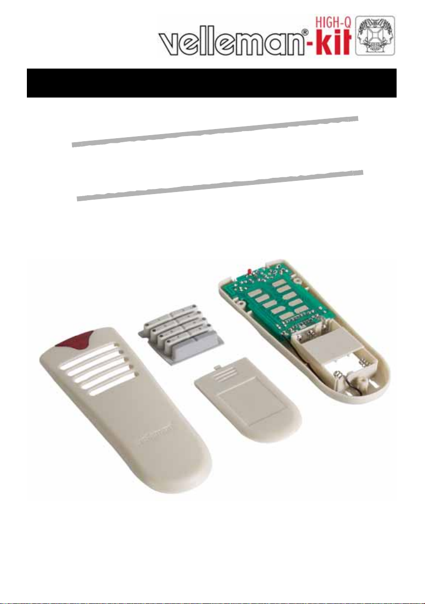
8 Channel RF transmitter
K
n
a
m
e
l
l
e
V
h
t
i
w
e
s
u
r
o
F
e
s
s
e
r
d
a
Total solder points: 63
Difficulty level: beginner 1 2 3 ⌧ 4 5 advanced
w
o
l
l
a
s
u
e
h
t
n
o
f
o
e
s
o
o
r
e
8
m
m
0
e
l
p
i
t
l
u
.
v
i
e
c
e
r
n
i
s
r
e
8
,
d
r
a
c
y
a
l
e
r
6
5
K8058
K8058
ILLUSTRATED ASSEMBLY MANUAL H8058IP-1
Page 2
Features & specifications
Features:
Works together with the K8056 relay card.
8 addresses allow the use of multiple receivers.
'all clear'- function.
Toggle or momentary mode for each key.
Open-field range up to 50m.
Rubber keypad.
Specifications:
• 433MHz operation
• LED function/mode indication
• Power supply: 3 AAA batteries (not included).
• Dimensions: 150 x 58 x 20mm (5.9" x 2.3" x 0.8")
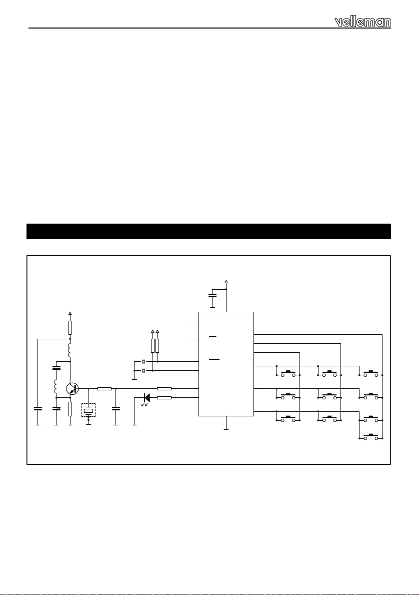
Schematic diagram.
C1
100n
GND+V
2
RA5/T1CKI/OSC1/CLKIN
RA0/CIN+/ICSPDAT
3
RA4/T1G/OSC2/CLKOUT
RA2/COUT/T0CKI/INT
4
RA3/MCLR/Vpp
5
RC5
6
RC4
7
RC3
GND
C3
56p
L2
COIL PCB 433
C2
1p
L1
COIL 1T 433
C4
4p7
GND
GND
R1
47
T1
MPSH10
R6
220
GND
R2
33K
X1
SAW433
GND
C5
100p
R4
33KR533K
J1
J2
Address selecti o n
GND
LED3RL
LD1
GND
+V+V
33K
R3
1K
470
R7
+V
1
VDD
IC1
RA1/CIN-/ICSPCLK
RC0
RC1
RC2
VSS
PIC16F630-I/P
14
GND
13
12
11
10
SW1
1
9
SW4
4
8
SW5
7
SW2
SW6
SW7
2
5
8
SW3
SW8
SW9
SHIFT
SW10
SHIFT
3
6
2
Page 3
Assembly hints
0
.
0
0
0
1. Assembly (Skipping this can lead to troubles ! )
Ok, so we have your attention. These hints will help you to make this project successful. Read them
carefully.
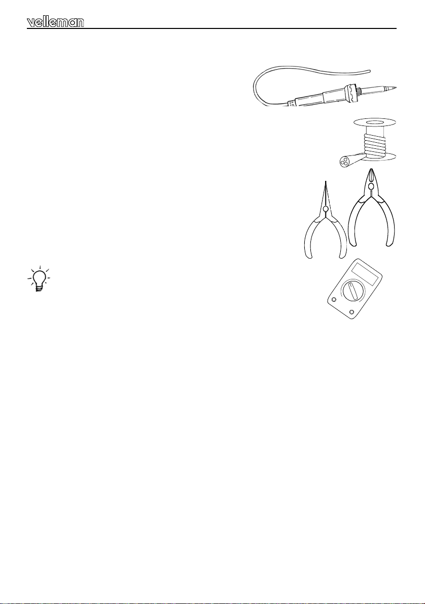
1.1 Make sure you have the right tools:
• A good quality soldering iron (25-40W) with a small tip.
• Wipe it often on a wet sponge or cloth, to keep it clean; then apply solder to the tip, to
give it a wet look. This is called ‘thinning’ and will protect the tip, and enables you to
make good connections. When solder rolls off the tip, it needs cleaning.
• Thin raisin-core solder. Do not use any flux or grease.
• A diagonal cutter to trim excess wires. To avoid injury when cutting excess
hold the lead so they cannot fly towards the eyes.
• Needle nose pliers, for bending leads, or to hold components in place.
• Small blade and Phillips screwdrivers. A basic range is fine.
For some projects, a basic multi-meter is required, or might be handy
1.2 Assembly Hints :
leads,
⇒ Make sure the skill level matches your experience, to avoid disappointments.
⇒ Follow the instructions carefully. Read and understand the entire step before you perform each
operation.
⇒ Perform the assembly in the correct order as stated in this manual
⇒ Position all parts on the PCB (Printed Circuit Board) as shown on the drawings.
⇒ Values on the circuit diagram are subject to changes.
⇒ Values in this assembly guide are correct*
⇒ Use the check-boxes to mark your progress.
⇒ Please read the included information on safety and customer service
⇒ * Typographical inaccuracies excluded. Always look for possible last minute manual updates,
indicated as ‘NOTE’ on a separate leaflet.
3
Page 4
Assembly hints
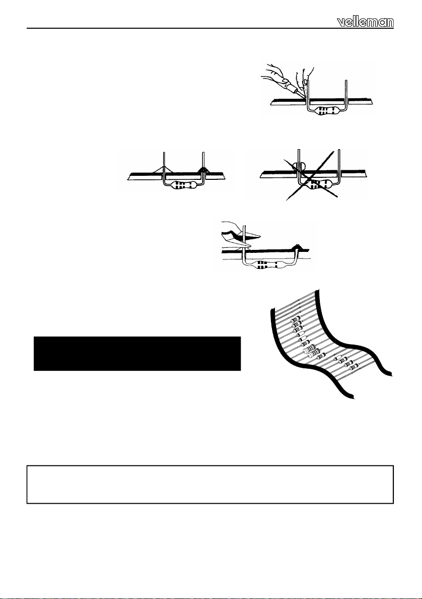
1.3 Soldering Hints :
1- Mount the component against the PCB surface and carefully
solder the leads
2- Make sure the solder joints are cone-shaped and shiny
3- Trim excess leads as close as possible to the solder joint
REMOVE THEM FROM THE TAPE ONE AT A TIME !
AXIAL COMPONENTS ARE TAPED IN
THE CORRECT MOUNTING SEQUENCE !
Velleman hereby certifies that the device K8058 meets the essential requirements and all other relevant
For the complete conformity declaration check out :http ://www .velleman.be/downloads/doC/CE_K8058.pdf
stipulations of directive 1999/5/EG and 1995/5/EC.
4
Page 5

Construction
C...
X...
.
1. Jumpers
J1
J2
J3
2. 1/8W Resistors
R...
R1 : 47 (4 - 7 - 0 - B)
R2 : 33K (3 - 3 - 3 - B)
R3 : 33K (3 - 3 - 3 - B)
R4 : 33K (3 - 3 - 3 - B)
R5 : 33K (3 - 3 - 3 - B)
R6 : 220 (2 - 2 - 1 - B)
R7 : 470 (4 - 7 - 1 - B)
3. SAW resonator.
CHECK THE POSITION
OF THE NOTCH!
X1 : SAW433
4. Ceramic Capacitors
C1 : 100nF (104, µ1)
C2 : 1pF (Red, purple)
C4 : 4,7pF (Black)
C3 : 56pF (56)
C5 : 100pF (101)
5. IC socket. Watch the position of the notch!
IC1 : 14p
J4
J5
J6
6. Coil
L1: 1 turn
7. Transistor
T1 : MPSH10
T.
8. LED. Watch the polarity!
LD1 : 3mm RED
A simple air core coil
has to be made as
5mm
shown in the diagram
using the jumper lead
supplied
COLOR= 2...5
First : Mount this LED like
in the drawing (fig. 1.0).
Solder one lead, check the
LD...
position, if necessary correct it by heating the soldering.
CATHODE
Next : solder the second connection.
FIG. 1.0
Last : Bend the LED exactly like the drawing
(fig. 2.0).
solderside
FIG. 2.0
5
Page 6

Construction
9. IC. Watch the position of the notch!
IC1 : VK8058 programmed Pic16F630.
10. Battery contacts
Solder a wire of 8cm (Ø 0,20mm)to the negative (-) connection of the PCB. The other end of
the wire will be soldered to the negative battery contact later on.
Solderside
Now place the battery contacts into the housing on their right places.
Positive battery lip
Common battery lip
Common battery lip
Negative battery lip
FIG. 3.0
1
2
3
4
6
4
3
2
1
FIG. 4.0
Page 7

First bend the battery lips over before closing the enclosure (fig. 5.0).
Connect now the wire that you earlier have mount to the negative battery lip.
FIG. 5.0
Negative battery lip
Positive battery
Connect a wire between the positive battery lip and positive connection on the pcb.
Construction
11. Sticker
Affix the supplied sticker to the backside of the housing, see fig 6.0
FIG. 6.0
Velleman
433,92 MHz
SRFCE
7
Page 8

Assembly
V
e
l
l
e
m
a
n
®
12. Assembly
Close the enclosure with the supplied screws.
8
DO NOT FASTEN THE
SCREWS TOO TIGHT!
Page 9

13. Keyboard Layout
Keyboard layout & use
1
3
5
7
2
4
6
8
SHIFT
14. Use
FIG. 7.0
When the batteries are inserted for the first time :
Channels 1..8 are configured as 'toggle' and are accessable by pressing button 1..8.
The indicator led will briefly light when a button is pressed.
Briefly pressing the shift button turns off all relays.
8 Addresses are available. Address 1 is the default address.
When the batteries are replaced :
The unit will remember its address and the 'toggle'/'momentary' setting for each channel.
Insert the batteries in the battery
compartment as indicated in fig. 8.0
and close the compartment.
Remark : Respect your national
and local laws when disposing of
empty batteries.
9
Page 10

Setup
15. Setup
Hold 'shift' until the LED lights to enter the 'set-up' mode.
Choose one of the following options by pressing the corresponding button :
(1) ‘Toggle’/’pulse’-selection.
(2) Display the current remote control address
(3) Change remote/relay card address
(4) Force remote/relay card address to address 1
(1) ‘Toggle’/’pulse’-selection (LED flashes once ) :
Allows you to select ‘toggle’ or ‘pulse’mode for each channel.
Pressing a channel button (1..8) repeatedly allows you to choose between 'toggle'- and 'pulse'-mode
for that particular channel (LED flashes once : pulse, two flashes : toggle).
Press 'shift' to leave this mode. Press ‘shift’ again to leave set-up mode.
(2) Display the current remote control address on the K8056 relay card (LED flashes twice) :
Relay LEDs display the address in binary fashion i.e. LD8 : LSB, LD1 : MSB
Press ‘shift’ to leave the set-up mode.
(3) Change the current address of the remote and relay card (available addresses : 1..8) (LED
flashes three times) :
Press button 1..8 to change the current address of the remote and the relay card.
The relay card will display the current address in binary fashion (see (2)).
Attention : All active cards will respond to this command (except when the ‘remote control’ jumper
on the relay card is set to ‘off’). Press ‘shift’ to leave this mode. Press ‘shift’ again to leave the set-up
mode.
4) Force the remote/relay card to address 1.
If the receiver (e.g. K8056) has been set to an address other than 1..8, you can force it to respond to
address 1.
Attention : All active cards will respond to this command (except when the ‘rem ote control’
jumper on the relay card is set to ‘off’). Press ‘shift’ to leave the set-up mode.
You can leave the 'set-up' mode at any given time by pressing the 'shift'-button repeatedly until the
LED turns off. If no button is pushed for a while, the unit will leave the 'setup'-mode and the LED will
turn off.
10
Page 11

15. PCB layout.
PCB
11
Page 12

VELLEMAN KIT NV
Legen Heirweg 33
9890 Gavere
Belgium Europe
Info ?: http://www.velleman.be
Modifications and typographical errors reserved
© Velleman Kit nv
H8058IP - 2004 - ED1
12
5 410329 315030
 Loading...