

Page 1
15 Channel IR transmitter
m
e
l
l
e
V
t
s
o
m
h
t
i
w
e
l
b
i
t
a
p
m
o
C
a
Total solder points: 53
Difficulty level: beginner 1 2 3 ⌧ 4 5 advanced
e
s
s
e
r
d
w
o
l
l
a
s
u
e
h
t
n
o
f
o
e
s
o
o
r
e
m
m
a
e
l
p
i
t
l
u
.
v
i
e
c
e
r
n
i
s
r
e
4
,
s
t
i
k
r
e
v
i
e
c
e
r
R
I
n
K8049
K8049
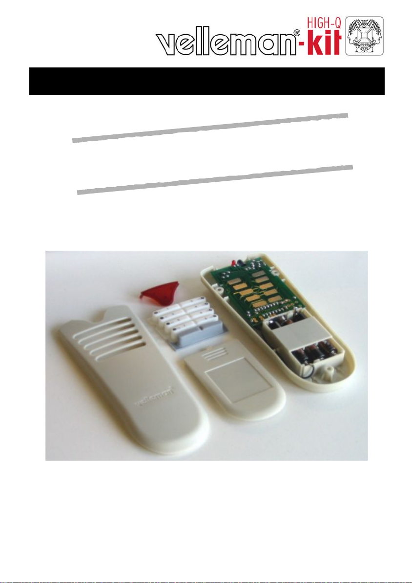
ILLUSTRATED ASSEMBLY MANUAL H8049IP-1
Page 2
Features & specifications
Features:
Works together with K6711, K6712, K6713, K8046, K8050, K4100, K4500, MK161, MK163,
MK164, …
4 addresses allow the use of multiple receivers in one room
Ergonomic design for extra comfort.
LED function indication.
Rubber keypad
Specifications:
• Power supply : 3 AAA batteries
• Up to 15 channels can be operated.
• Dimensions : 150 x 58 x 22mm / 5,9 x 2,3 x 0,86”
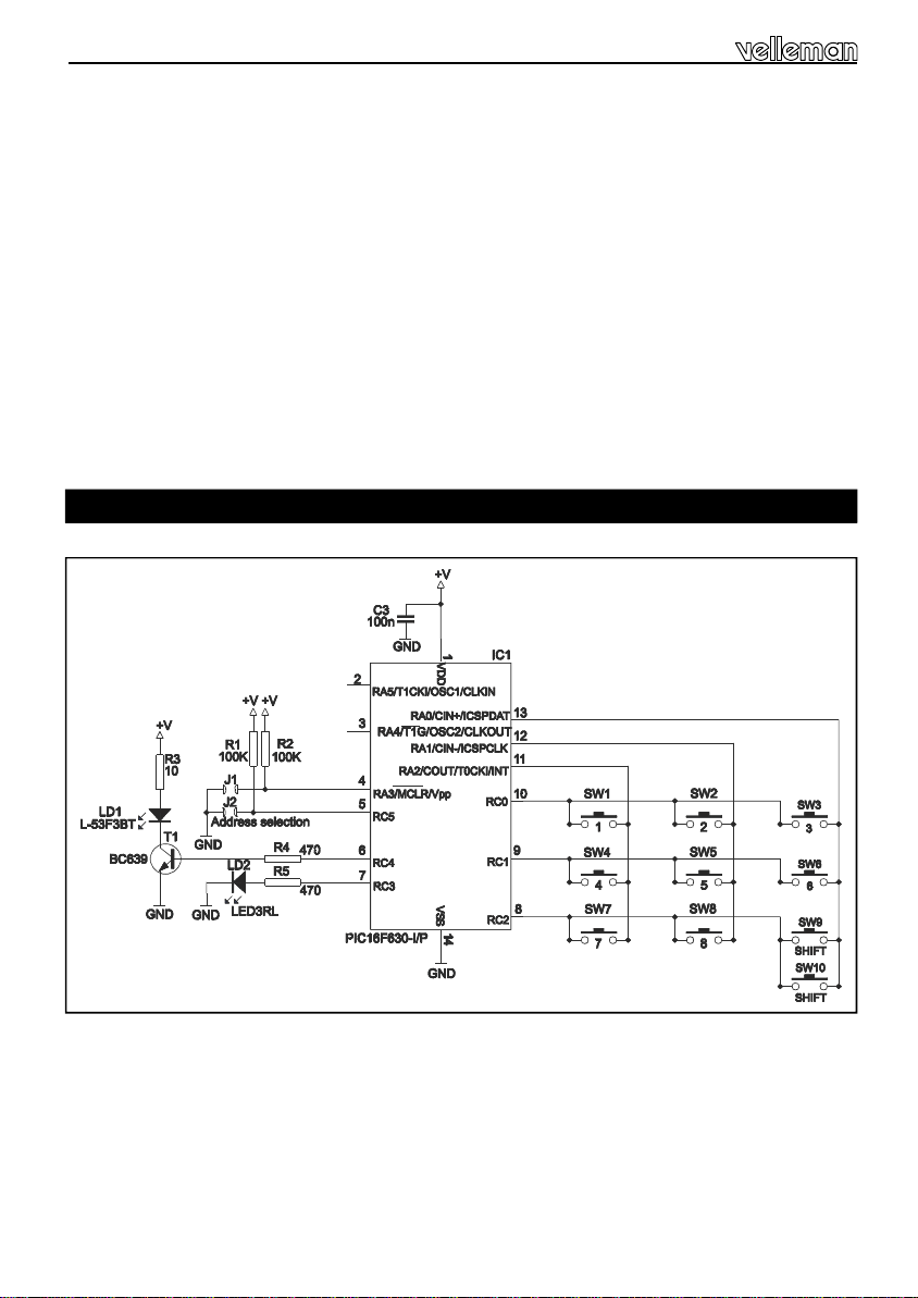
Schematic diagram.
2
Page 3
Assembly hints
0
.
0
0
0
1. Assembly (Skipping this can lead to troubles ! )
Ok, so we have your attention. These hints will help you to make this project successful. Read them
carefully.
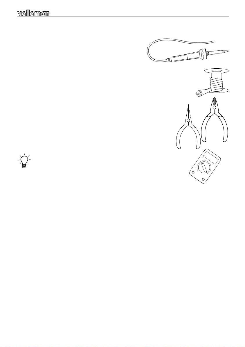
1.1 Make sure you have the right tools:
• A good quality soldering iron (25-40W) with a small tip.
• Wipe it often on a wet sponge or cloth, to keep it clean; then apply solder to the tip, to
give it a wet look. This is called ‘thinning’ and will protect the tip, and enables you to
make good connections. When solder rolls off the tip, it needs cleaning.
• Thin raisin-core solder. Do not use any flux or grease.
• A diagonal cutter to trim excess wires. To avoid injury when cutting excess
hold the lead so they cannot fly towards the eyes.
• Needle nose pliers, for bending leads, or to hold components in place.
• Small blade and Phillips screwdrivers. A basic range is fine.
For some projects, a basic multi-meter is required, or might be handy
1.2 Assembly Hints :
leads,
⇒ Make sure the skill level matches your experience, to avoid disappointments.
⇒ Follow the instructions carefully. Read and understand the entire step before you perform each
operation.
⇒ Perform the assembly in the correct order as stated in this manual
⇒ Position all parts on the PCB (Printed Circuit Board) as shown on the drawings.
⇒ Values on the circuit diagram are subject to changes.
⇒ Values in this assembly guide are correct*
⇒ Use the check-boxes to mark your progress.
⇒ Please read the included information on safety and customer service
⇒ * Typographical inaccuracies excluded. Always look for possible last minute manual updates,
indicated as ‘NOTE’ on a separate leaflet.
3
Page 4
Assembly hints
1.3 Soldering Hints :
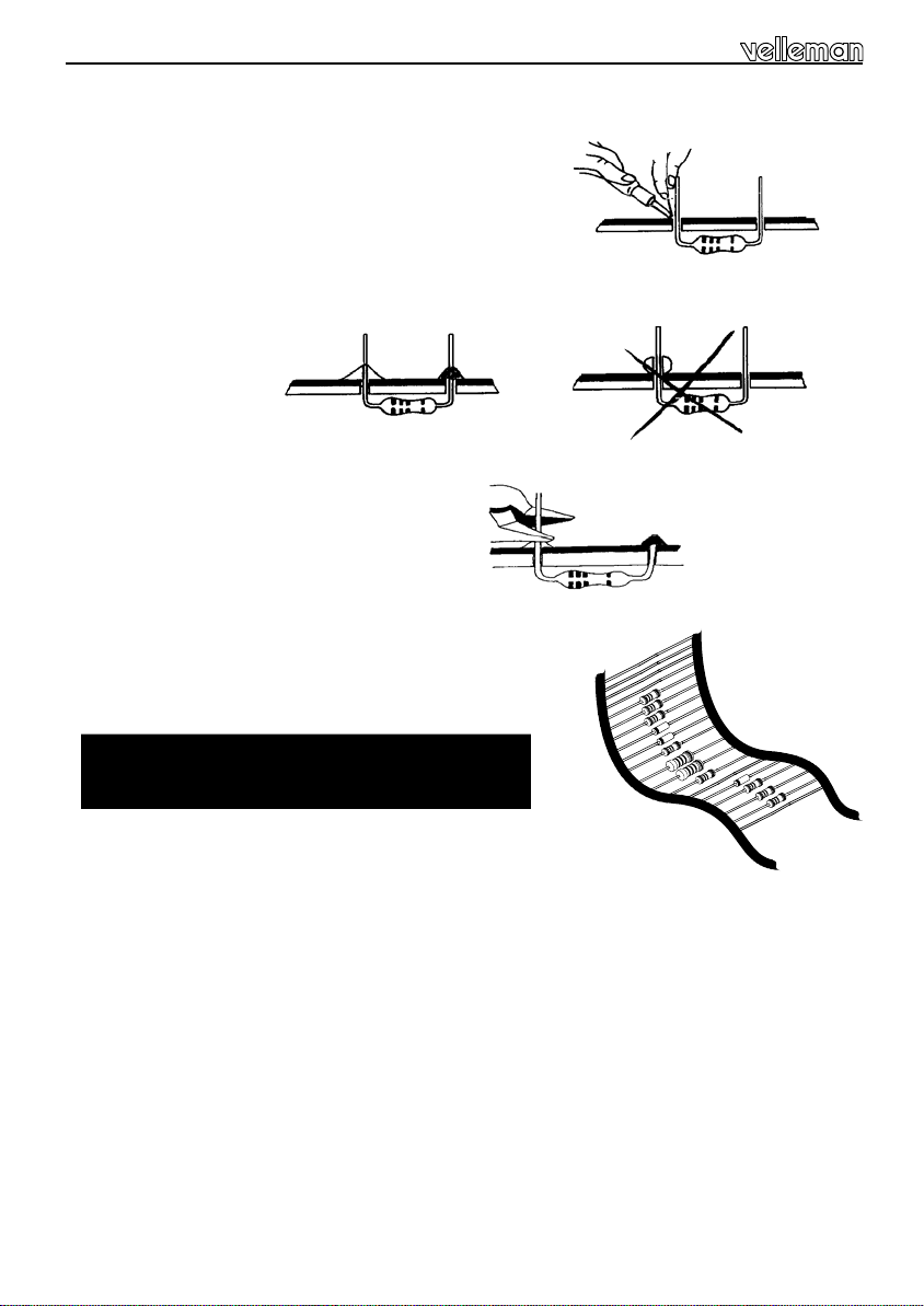
1- Mount the component against the PCB surface and carefully
solder the leads
2- Make sure the solder joints are cone-shaped and shiny
3- Trim excess leads as close as possible to the solder joint
REMOVE THEM FROM THE TAPE ONE AT A TIME !
AXIAL COMPONENTS ARE TAPED IN
THE CORRECT MOUNTING SEQUENCE !
4
Page 5
Construction
C...
I
R
-
L
E
D
3
m
m
L
E
D
1. Jumpers
J1
J2
J3
2. 1/8W Resistors
J4
J5
J6
R...
R1 : 100K (1-0-4-B)
R2 : 100K (1-0-4-B)
R3 : 10 (1-0-0-B)
R4 : 470 (4-7-1-B)
R5 : 470 (4-7-1-B)
3. Ceramic Capacitor
C3 : 100nF (104, µ 1)
4. IC socket. Watch the position of the
notch!
IC1 : 14p
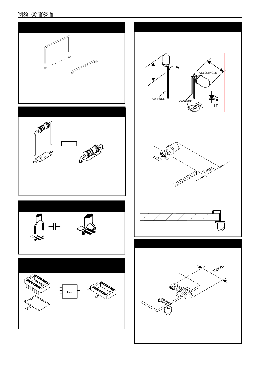
5. LEDs. Watch the polarity!
LD2 : 3mm RED
First : Bend the leads exactly like the drawing.
(Fig 1.0)
m
m
9
FIG. 1.0
m
m
9
Next : Mount this LED like in the drawing (fig.
2.0). Solder one lead, check the position, if
necessary correct it by heating the soldering.
Last solder the second connection.
Bend the LED exactly like the drawing (fig.
FIG. 2.0
3.0).
FIG. 3.0
6. IR - LED. Watch the polarity!
LD1
Fit the IR LED horizontally and in line with the
PCB, (fig 4.0).
FIG. 4.0
Pay attention to the polarity!
5
Page 6

Construction
7. Transistor
T1 : BC639
Attention : Mount the transistor on the solder side!
Now bend the transistor towards the pcb, away from the IR & 3mm LED.
FIG. 5.0
Make sure the transistor
FIG. 6.0
8. IC. Watch the position of the notch!
IC1 : VK8049 programmed Pic16F630.
T1
connections do not contact
any other parts of the
circuit.
9. Battery contacts
Solder a wire of 7cm (Ø 0,20mm)to the negative (-) connection of the PCB. The other end of
the wire will be soldered to the negative battery contact later on.
Solderside
FIG. 7.0
6
Page 7

Now place the battery contacts into the housing on their right places.
Positive battery lip
Common battery lip
Common battery lip
Negative battery lip
4
2
3
1
Connect now the wire that you earlier have mount to the negative battery lip.
Negative battery lip
Positive battery lip
Connect a jumper between the positive battery lip and positive connection on the pcb.
Construction
1
2
3
4
FIG. 8.0
7
Page 8

Assembly
10. Assembly
First bend the battery lips over before closing the enclosure.
Close the enclosure with the supplied screws.
FIG. 9.0
8
Page 9

11. Keyboard Layout
Keyboard layout
1
3
5
7
1
Mute
2
Power
3
Volume up
3
Preset up
5
Volume down
6
Preset down
7
Source
8
Tuner seek
2
4
6
8
SHIFT
FIG. 10
Insert the batteries in the battery
compartment as indicated in fig. 10
and close the compartment.
Remark : Respect your national
and local laws when disposing of
empty batteries.
9
Page 10

Mode selection & Use
12. Mode selection
At first power up, mode 1 is automatically selected.
Press and hold SHIFT to change mode. Led starts flashing.
Press button 1..8 to select desired mode as shown below.
Hint : When the batteries are inserted, the led flashes 1..4 times indicating the selected mode.
Key Description
1 'K6710 emulation with D4 mounted'- mode. Allows control of MK161/K8050/K6711/12/13.
15 channels available ('shift' & '8' = all clear). Shift is cleared after each key press.
2 'K6710 emulation with D6 mounted'-mode. Allows control of MK161/K8050/K6712/13. 15
channels available ('shift' & '8' = all clear). Shift is cleared after each key press.
3 'K6710 emulation with D5 mounted'-mode. Allows control of MK161/K8050/K6712/13. 15
channels available ('shift' & '8' = all clear). Shift is cleared after each key press.
4 Allows simultaneous control of K4100/K4500, MK163/MK164, MK161 and
K8050/K6711/12/13
5 Identical to 1 but ‘shift’ is not cleared after each key press.
6 Identical to 2 but ‘shift’ is not cleared after each key press.
7 Identical to 3 but ‘shift’ is not cleared after each key press.
8 Identical to 4 but ‘shift’ is not cleared after each key press.
13. Use
To access channel 1..8 :
Press button for channel 1..8.
Holding the button will result in continuous transmission, led will flash indicating transmission.
To access channel 9..16 :
Briefly press 'shift'. Led will light indicating that 'shift' has been pressed.
Press button 1..8 to access channel 9..16
Holding the button will result in continuous transmission.
If no button is pressed after 'shift' has been pressed, the 'shift'-led will turn off in about 10s, hereby
cancelling the 'shift'-selection.
Pressing 'shift' repeatedly toggles between shift-on and shift-off.
10
Page 11

14. PCB layout.
PCB
11
Page 12

VELLEMAN KIT NV
Legen Heirweg 33
9890 Gavere
Belgium Europe
Info ?: http://www.velleman.be
Modifications and typographical errors reserved
© Velleman Kit nv
H8049IP - 2003 - ED2
5 410329 291983
 Loading...