

Page 1
Total solder points: 239
Difficulty level:
beginner 1 2 3 4 5 advanced
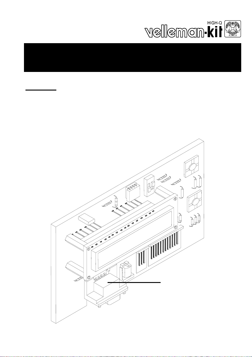
8 Input programmable messageboard
with LCD & serial interface
Features :
Add an LCD display to any low-tech application and make it look high-te ch !
Replace up to 9 indicators or lamps by one single backlit LC D.
Recall messages simply by pressing a button.
Inputs accept dry contacts, open collectors and logic levels .
No programming skills required !
Store up to 9 sixteen-character messages in non-volatile E EPROM memor y .
4 operating modes :
1) Display the status of all inputs simult aneously .
2) Display all active inputs.
3) Display active input with highest priority .
4) Display text messages in a ‘tickertape’-fashi on.
A default message can be entered and is display ed when no inputs are active.
Messages can be transferred to the K8045 from any PC or terminal.
Free message transfer software and source code for the K8045 is availabl e
from www.velleman.be
Wireless data transfer between PC/terminal and K 8045 is possible with op-
tional RX/TX433 modules.
1 on-board pushbutton available for y our application.
K8045
Specifications :
Inputs : 8 inputs (24Vmax)
Display : 16 character 1 line supertwist backlit LCD
Communication : RS232 2400/N/8/1 no handshaking
Power supply : 9-12VDC/150mA adapter or
2x9VAC/150mA transformer
Modifications reserved
ILLUSTRATED ASSEMBLY MANUAL H8045IP-1
Dimensions : 124x73x30mm max.
Page 2
Assembly hints
0
.
0
0
0
1. Assembly (Skipping this can lead to troubles ! )
Ok, so we have your attention. These hints will help you to make this project
successful. Read them carefully.
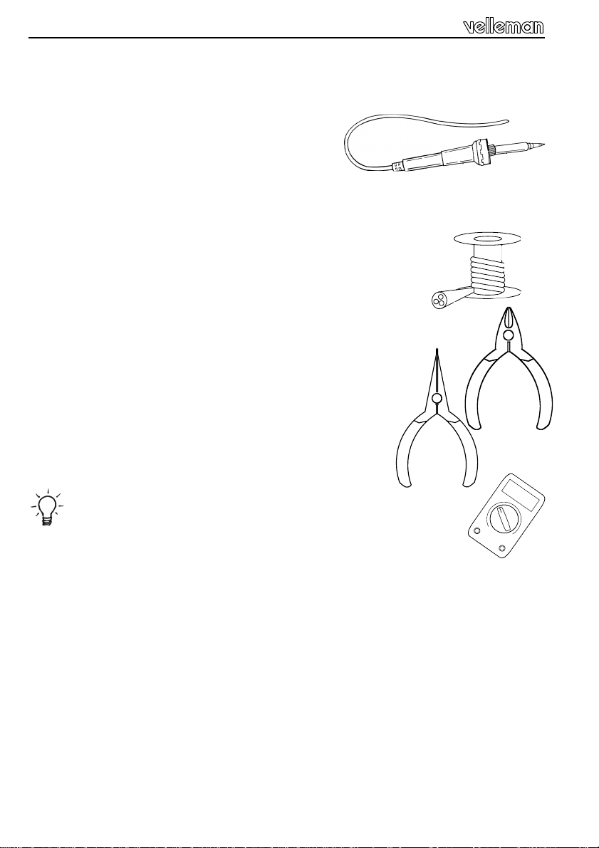
1.1 Make sure you have the right tools:
• A good quality soldering iron (25-40W) with a
small tip.
• Wipe it often on a wet sponge or cloth, to keep it clean; then apply solder to
the tip, to give it a wet look. This is called ‘thinning’ and will protect the tip,
and enables you to make good connections. When solder
rolls off the tip, it needs cleaning.
• Thin raisin-core solder. Do not use any flux or grease.
• A diagonal cutter to trim excess wires. To avoid injury when cutting
excess leads, hold the lead so they cannot fly towards the eyes.
• Needle nose pliers, for bending leads, or to hold components in place.
• Small blade and phillips screwdrivers. A basic range
is fine.
For some projects, a basic multi-meter is required, or might
be handy
1.2 Assembly Hints :
⇒ Make sure the skill level matches your experience, to avoid disappointments.
⇒ Follow the instructions carefully. Read and understand the entire step before
you perform each operation.
⇒ Perform the assembly in the correct order as stated in this manual
⇒ Position all parts on the PCB (Printed Circuit Board) as shown on the draw-
ings.
⇒ Values on the circuit diagram are subject to changes.
⇒ Values in this assembly guide are correct*
⇒ Use the check-boxes to mark your progress.
⇒ Please read the included information on safety and customer service
* Typographical inaccuracies excluded. Always look for possible last minute
manual updates, indicated as ‘NOTE’ on a separate leaflet.
2
Page 3
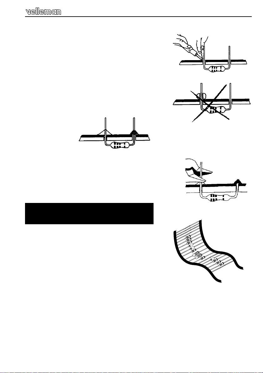
1.3 Soldering Hints :
1- Mount the component against the PCB surface
and carefully solder the leads
2- Make sure the solder joints are cone-shaped
and shiny
3- Trim excess leads as close as possible to the solder joint
AXIAL COMPONENTS ARE TAPED IN
THE CORRECT MOUNTING SEQUENCE !
REMOVE THEM FROM THE TAPE ONE AT A TIME !
Assembly hints
3
Page 4
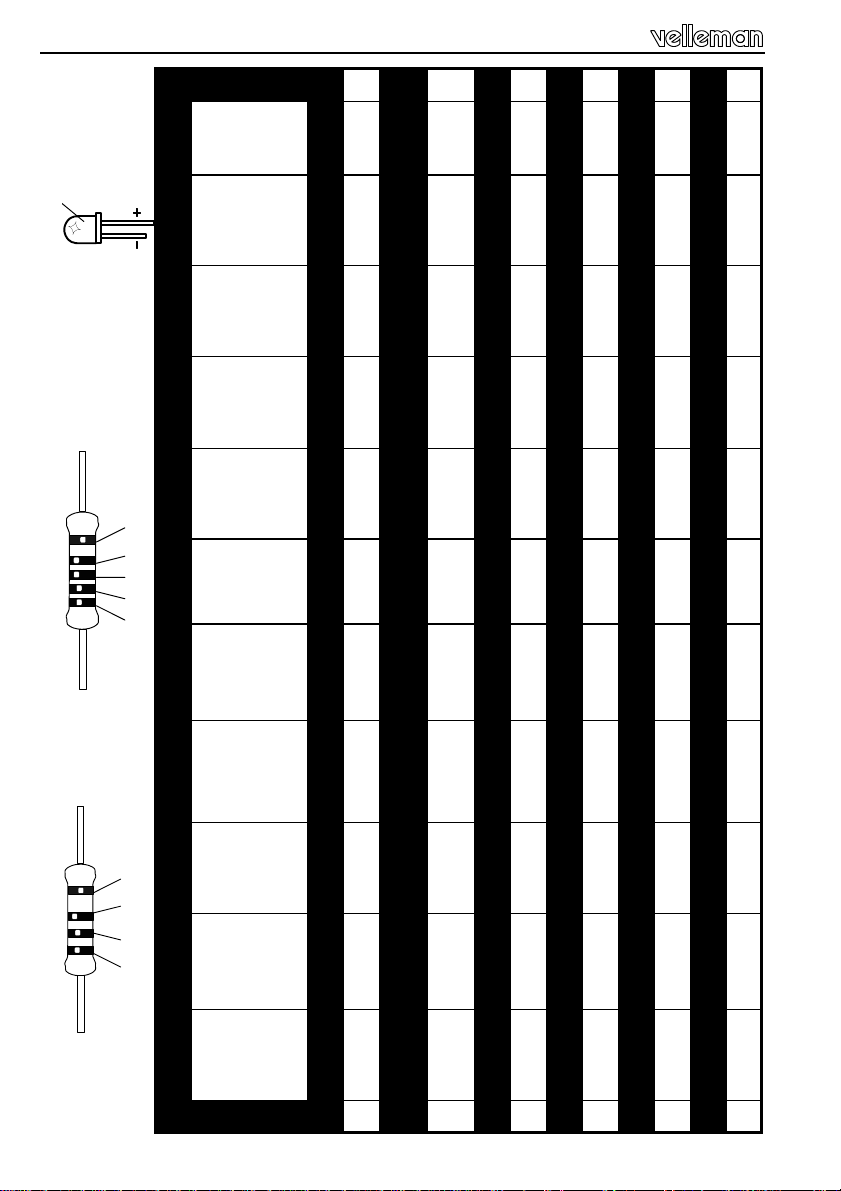
Color code table
COLOR= 2...5
CO LO R = 2… 5
1%
C O D
KLEUR
CODIFI-
COLOUR
FARB
FARGE-
FARVE-
E
KODE
CATION
DES
COU-
CODE
KODE
KODE
KODE
LEURS
4
5%
4K7= ( 4 - 7 - 2 - B )
4K7= ( 4 - 7 - 0 - 1 - 1 )
FÄRG
VÄRI
CODIGO
CODIGO
I P E SF S DK N D GB F NL
CODICE
C O D E
SCHEMA
KOODI
ORES
DE COL-
DE
CORES
COLORE
0 Nero Preto Negro Musta Svart Sort Sort Schwarz Black Noir Zwart 0
1 Marrone Castanho Marrón Ruskea Brun Brun Brun Braun Brown Brun Bruin 1
Rojo Punainen Röd Rød Rød Rot Red Rouge Rood 2
nado
2 Rosso Encar-
Oranssi Orange Orange Orange Orange Orange Orange Oranje 3
jado
Laranja Naran-
ciato
3 Aran-
4 Giallo Amarelo Amarillo Keltainen Gul Gul Gul Gelb Yellow Jaune Geel 4
5 Verde Verde Verde Vihreä Grön Grøn Grønn Grün Green Vert Groen 5
6 Blu Azul Azul Sininen Blå Blå Blå Blau Blue Bleu Blauw 6
7 Viola Violeta Morado Purppura Lila Violet Violet Violet Purple Violet Paars 7
8 Grigio Cinzento Gris Harmaa Grå Grå Grå Grau Grey Gris Grijs 8
9 Bianco Branco Blanco Valkoinen Vit Hvid Hvidt Weiss White Blanc Wit 9
A Argento Prateado Plata Hopea Silver Sølv Sølv Silber Silver Argent Zilver A
B Oro Dourado Oro Kulta Guld Guld Guldl Gold Gold Or Goud B
Page 5
Construction
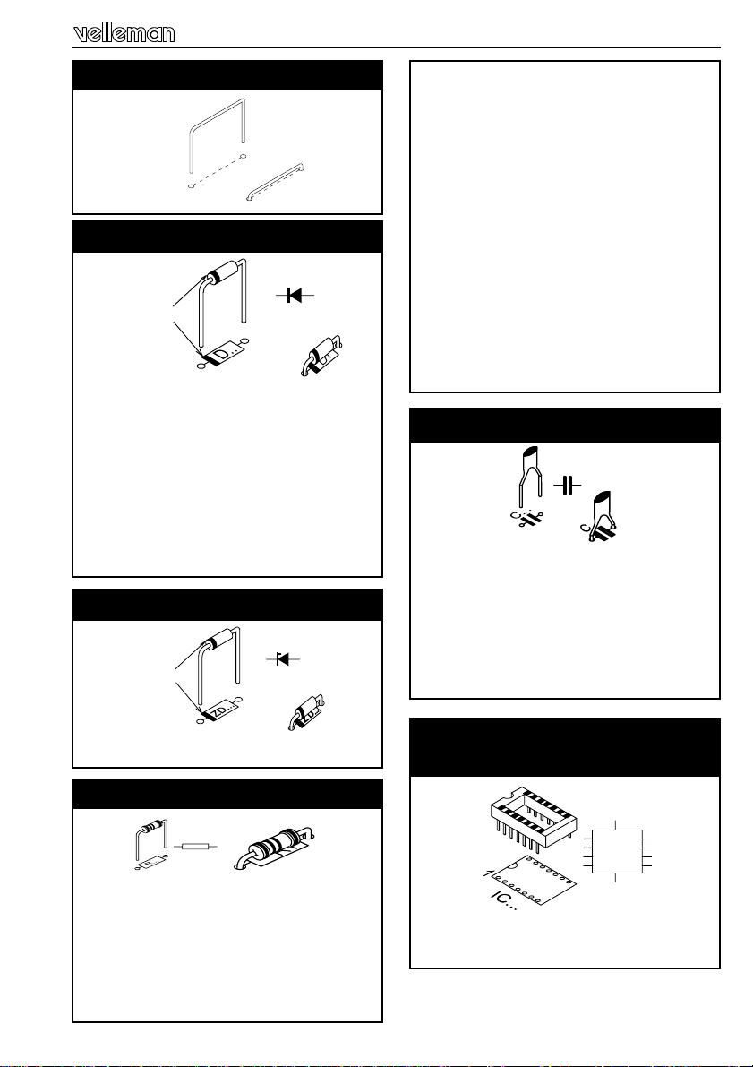
1. Jumperwire
J1
J2
J3
2. Diodes (Check the polarity)
CATHODE
D...
D1 : 1N4007
D2 : 1N4007
D3 : 1N4148
D4 : 1N4148
D5 : 1N4148
D6 : 1N4148
D7 : 1N4148
D8 : 1N4148
D9 : 1N4148
D10 : 1N4148
3. Zenerdiodes (Check the polarity)
CATHODE
ZD...
R10 : 1K (1 - 0 - 2 - B)
R11 : 1K (1 - 0 - 2 - B)
R13 : 1K (1 - 0 - 2 - B)
R14 : 1K (1 - 0 - 2 - B)
R16 : 1K (1 - 0 - 2 - B)
R17 : 1K (1 - 0 - 2 - B)
R19 : 1K (1 - 0 - 2 - B)
R20 : 1K (1 - 0 - 2 - B)
R22 : 1K (1 - 0 - 2 - B)
R23 : 1K (1 - 0 - 2 - B)
R25 : 1K (1 - 0 - 2 - B)
R26 : 1K (1 - 0 - 2 - B)
R28 : 1K (1 - 0 - 2 - B)
R29 : 1K (1 - 0 - 2 - B)
R30 : 22E0 (2 - 2 - 0 - B)
R31 : 10K (1 - 0 - 3 - B)
5. Capacitors
C...
C2 : 100nF (104)
C3 : 100nF (104)
C4 : 100nF (104)
C5 : 100nF (104)
C7 : 15pF (15)
C8 : 15pF (15)
ZD1 : 5v1
4. Resistor
R...
R1 : 10K (1 - 0 - 3 - B)
R2 : 10K (1 - 0 - 3 - B)
R3 : 10K (1 - 0 - 3 - B)
R4 : 100K (1 - 0 - 4 - B)
R5 : 1K (1 - 0 - 2 - B)
R7 : 1K (1 - 0 - 2 - B)
R8 : 1K (1 - 0 - 2 - B)
6. IC socket
(Watch the position of the notch)
1
IC...
IC1 : 28p
IC2 : 8p
5
Page 6
Construction
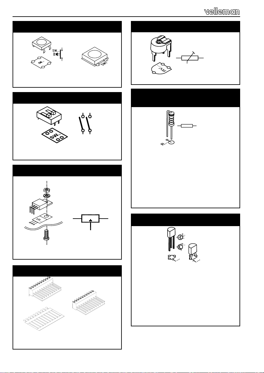
7. Push buttons
SW2
SW3
8. DIP switch
2
1
SW...
1
SW1 : DIP-2
9. Voltage regulator
M3 NUT
M3 LOCK WASHER
VOLTAGE REGULATOR
PCB
M3 BOLT
VR1 : UA7805
10. Connector
1
VR...
I O
11. Trim potentiometer
RV...
RV1 : 10K
12. 1/4W Resistors
(check the color code)
R...
R6 : 1K (1 - 0 - 2 - B)
R9 : 1K (1 - 0 - 2 - B)
R12 : 1K (1 - 0 - 2 - B)
R15 : 1K (1 - 0 - 2 - B)
R18 : 1K (1 - 0 - 2 - B)
R21 : 1K (1 - 0 - 2 - B)
R24 : 1K (1 - 0 - 2 - B)
R27 : 1K (1 - 0 - 2 - B)
13. Transistors
T1 : BC557
T2 : BC557
T3 : BC557
T4 : BC557
T5 : BC557
T6 : BC557
T7 : BC557
T8 : BC557
SK1 : 3p
SK8 : 12p
6
Page 7

Construction
14. Header
SK3 : 3p
15. DC-jack
SK2
16. SUB-D connector
SK5 : SUB-D 9p female
17. Electrolytic capacitors
C...
C6 : 10µF
C1 : 220µF/35V
18. Quartz chrystal
X...
X1 : 4MHZ
19. IC’s
IC1 : VK8045 (PIC16C57)
IC2 : 24C02A
20. Shunt selection
RS232 cable operation
1
E
BL
A
C
1
Wireless link
F
R
1
1
7
Page 8

LCD assembling
21. LCD assembling
Cut the 20 pole connector to a 16 pole connector.
Diagonal cutter
Mount the 16 pole female connector. (see fig. 2.0)
Mount 2x 6 pole male connectors.
Pay attention : The four center connections of the LCD remain unused.
Make sure that the longest pins aim towards the main PCB. (See Fig. 3.0)
FIG.1.0
FIG.2.0
FIG.3.0
8
Page 9

Assembly
22. Assembly
Fit the display at the component side of the base PCB using four M2,5 bolts together with four 15mm spacers. Fix the display using four M2,5 bolts at the solder side of the base PCB and check that the display is at right angles to the
base PCB.
Now you can solder the pinheader.
Diagonal cutter
9
Page 10

Connection
23. Connection
1. Hook-up when using an adapter :
2. Hook-up when using a transformer
9 –12VDC / 150mA
10
K8045
SW3
GND
8
7
6
5
4
3
2
1
VB
VA
GND
120 - 220 VAC
L
Fuse : 250mA T
2 X 9VAC/150mA
N
TRANSFORMER
Page 11

Control options
24. Control options
How to construct an RS232 cable :
3
5
3
5
TO PC
SUBD 9 pole fem a le
TO K8045
SUBD 9 pole male
2-3 meter max.
Or you can buy a pre-assembled cable. Careful : this is not a null-modem cable
How to establish a wireless link :
Wireless data transfer between the PC/terminal and the K8045 is possible by
means of optional RF transmitter/receiver modules (Velleman part# TX433/
RX433). Transmission quality depends on your environment. Other RF sources
might interfere with your signal (and will cause occasional ‘garbage’ on-screen).
TX433
A
9V Battery
+
-
3
Z
5
R
Z : 5V1 zenerdiode 0,6W
A : antenna (30 - 40cm)
R : 3K9 resistor (orange - white - red)
To pc
SUBD 9 pole female
The receiver is mounted on the left hand side of the K8045 board. Watch the
position, the coils point to the LCD of the K8045. If you choose wireless operation, make sure to set jumper SK3 to ‘RF’
11
Page 12

Testing
25. Testing
Turn RV1 (contrast) fully anti-clockwise.
Set dipswitches SW1 (mode) to the ‘off’-position.
Set jumper SK3 for ‘cable’-operation but do not connect a serial cable
Connect the supplied wired female connector to SK8
Apply power (for power requirements, see pag. 10)
The LCD should initialise and the following text should appear :
K8045 Vxxxxxxxx (‘x’ indicates software version)
If the message ‘EEPROM FAILURE’ appears, check the position of IC2 and/or
re-check the complete assembly
Next, the display will show : 1 2 3 4 5 6 7 8
Check input 1 by shorting the left hand brown and the black wire. An ‘x’ appears
next to the ‘1’ on the screen, indicating ‘input active’
Check all inputs (brown to grey) in a similar fashion.
Next, flip dipswitch 2 of SW1 to the ‘ON’ position.
The display should display ‘9’ (the ninth message is displayed when no inputs
are active). Repeat the input test as above, but now the display will show the
active input only
RS232 interface setup :
Hook-up a serial cable (for details, see pag. 11) between a free serial port of
your computer/terminal and the K8045. You can download free software from
our website www.velleman.be, which allows you to transfer messages from the
PC to your K8045 and which allows you to display messages on you K8045.
You can also use a terminal or terminal emulation program to manually enter
messages. Terminal settings are :
Baudrate : 2400
Parity : none
Databits : 8
Stopbits : 1
No handshaking
12
Page 13

Message entering
26. Entering messages with a terminal program :
The K8045 can store 9 sixteen-character messages, 1 for each input and a 9th
which is displayed when no inputs are active.
Briefly press SW2 ‘PROG’ to enter program mode
The display shows ‘INPUT 1...9 / S / Q : ‘ and a flashing cursor
To enter a message for input 1 :
Type ‘1’ ‘ENTER’
The unit now displays ‘TRIGGER (1/0):’ and a flashing cursor
If you want the message to appear when the input is active (grounded),
type ‘0’ ‘ENTER’
In case you want the message to appear when the input is not active (left open),
Type ‘1’ ‘ENTER’
(If you do not want to change the settings for this input, press ‘BACKSPACE’ to
return to the previous menu)
The display now show the current message for this input.
If you do not wish to change the message for this input, press ‘BACKSPACE’ to
return to the input selection menu
If you wish to change the current message, simply type a new message and
press ‘ENTER’
Your message is now stored and the unit returns to the input selection menu
You can now enter messages for all inputs (1..9).
Message 9 is displayed when no input is active and does not allow you to enter
a trigger setting.
To exit programming mode, type ‘Q’ (capital).
(Note : You can download software from our
website www.velleman.be which makes it very
easy to store, edit and transfer messages, without the need for a terminal program)
13
Page 14

Operating modes
27. Operating modes :
The K8045 features 4 operatin g modes, se lectable w ith dipsw itch S W1.
To ensure correct operation, disconnect p ower before changing dip switch posi tion.
(Program mode can be selected at all ti mes, no need to disconnect pow er)
1) Display the sta tus of all in puts simulta neously
2) Display all active inputs
3) Display active inp ut with highe st priority
4) Display text mess ages in a ‘tickertap e’-fashion
1) Display the status of all inputs simultaneously :
All inputs are displayed. An ‘x’ appears on the right hand side of an active (ground ed) input.
2) Display all active inputs :
MODE 1 2
1
2
3
4
DIPSWITCH SW1
OFF OFF
OFF ON
ON OFF
ON ON
For every active i nput, a corr esponding mes sage is dis played. The re is a del ay between
each message, to allow the user to read the message. Message 9 is displ ayed when no
inputs are active.
3) Display active input with highest priority :
Message 1 has highest priority , message 8 has lowest p riority .
Only one message w ill be display ed. Message 9 is displ ayed when no inputs are active.
4) Display text messages in a ‘tickertape’-fashion :
This mode allows you to send messages to the K8045 from a remote location by either
RS232 cable or opt ional wireles s link (see page 11) a nd display them on-scr een. If the
message exceeds 16 ch aracters, th e message scro lls to the le ft.
An ID# can be assigne d to the K8045 r anging fro m 0 to 9 (de fault : 0). Th is allows y ou to
determine which K8 045 will recei ve and disp lay the mess age, which i s handy for w ireless
link applications. In this w ay, up to ten K8 045 units can be indiv idually addressed.
You can download a small program from our
website www.velleman.be which allows you to
set the ID # and send messages in a simple
fashion to your K8045. The source code is supplied, for users who w ould like to mod ify the code
for their proper applications.
14
Page 15

Options & examples
28. Options & examples
Options :
RF wireless link : ......................................................................... RX433/TX433
HQ supertwist LCD display : .........................................................LCD1601ASL
Application examples :
1. Home alarm system : let your alarm system tell you what sensor has
been triggered
2. Replace car indicator lamps
15
Page 16

Options & examples
3. Application with K8023 “Two wire 10-channel remote control”
GND
+ Vext
10
9
8
7
6
5
4
3
2
1
- VTX
+ VTX
P8023S
10
9
8
7
6
5
4
3
2
1
COM
+ VTX
K8023
K8045
12 ... 15Vin
P8023R
12V / 300mA
GND
GND
8
7
6
5
4
3
2
1
VB
VA
GND
2 x 9 VAC / 150mA
16
Page 17

PCB
&
DIAGRAMS
17
Page 18

PCB
PCB
18
Page 19

Diagram
Diagrams
19
Page 20

VELLEMAN COMPONENTS NV
Legen Heirweg 33
9890 Gavere
Belgium Europe
Info & support: www.velleman.be
Modifications and typographical errors reserved
© Velleman Components NV
H8045IP - 2002 - ED1
 Loading...