

Page 1

Total solder points: 293
Difficulty level:
beginner 1o 2o 3þ 4o 5oadvanced
12V, Ten channel light
effect generator
Features:
K8044
þ Ten, 12V/400mA outputs.
þ To control cold-cathode fluorescent lamps (using FLPS adapter), light
bulbs, LED’s and “solid state” relays, ...
þ For use as advertisement lighting, party lights, discos, eye-catcher,...
þ Ten pre-programmed light patterns selectable with a push button.
þ The number of used channels is adjustable.
þ Adjustable speed.
þ Led indication for every output.
þ 12V operation possible for use in cars.
Specifications :
• Power supply : 12V DC
• Outputs : 12V DC/400mA per channel (Total : max 4A)
• Dimensions : 140 x 100 x 27mm / 5,5 x 3,9 x 1,1”
Options (Velleman ordernumbers) :
Ú Power supply for cold-cathode fluorescent lamps : FLPS (300mm) or
FLPS1 (100mm)
Ú Cold-cathode fluorescent lamps : FL(xx) – (100 or 300mm).
Modifications reserved.
ILLUSTRATED ASSEMBLY MANUAL H8044IP-1
Page 2
2
VELLEMAN Components NV
Legen Heirweg 33
9890 Gavere
Belgium Europe
www.velleman.be
www.velleman-kit.com
Page 3
0.000
Assembly hints
1. Assembly (Skipping this can lead to troubles ! )
Ok, so we have your attention. These hints will help you to make this project successful. Read them carefully.
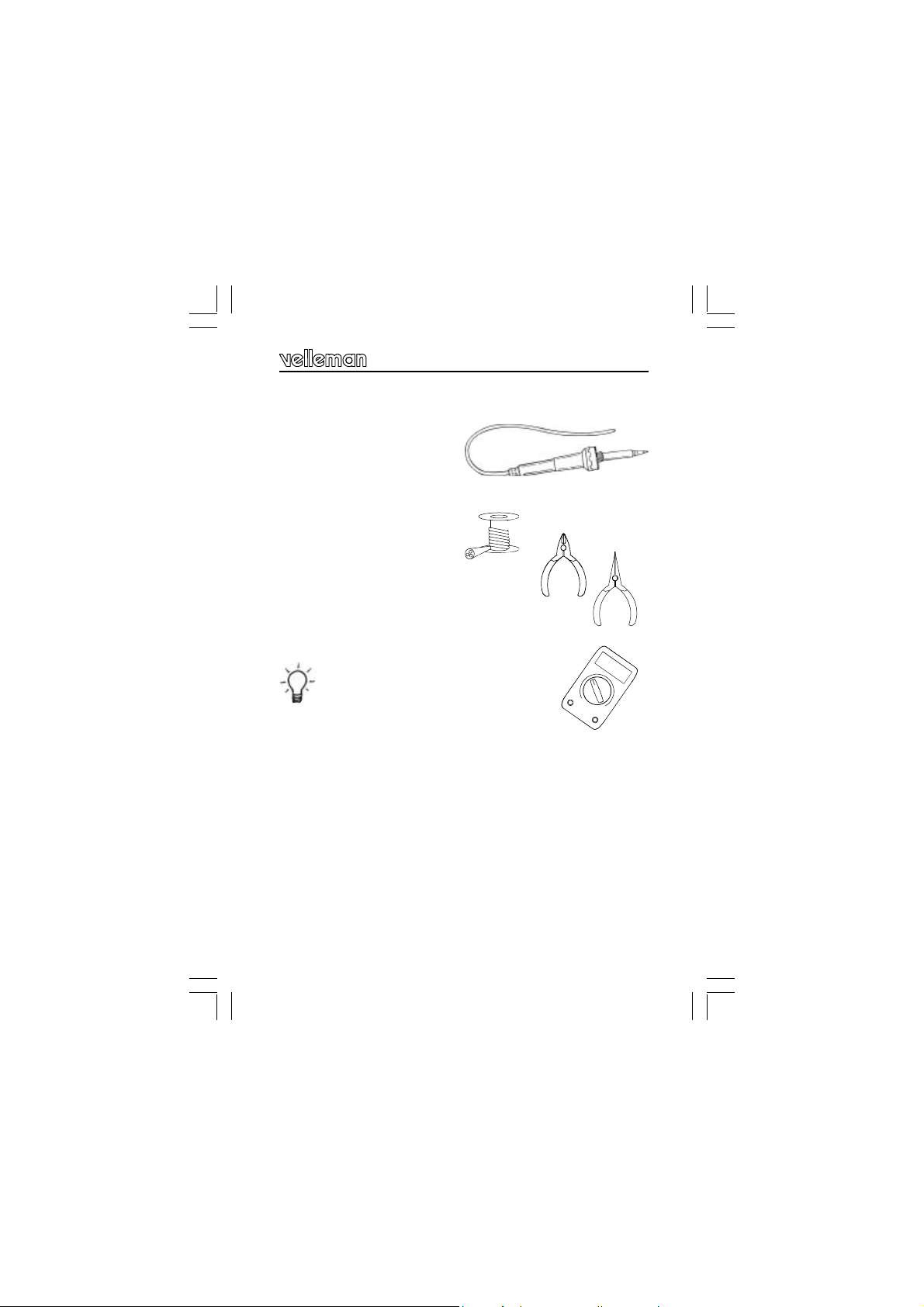
1.1 Make sure you have the right tools:
• A good quality soldering iron (2540W) with a small tip.
• Wipe it often on a wet sponge or cloth, to keep it clean; then apply solder to the
tip, to give it a wet look. This is called ‘thinning’ and will protect the tip, and enables you to make good connections. When solder rolls off the tip,
it needs cleaning.
• Thin raisin-core solder. Do not use
any flux or grease.
• A diagonal cutter to trim excess wires. To avoid injury
when cutting excess leads, hold the lead so they
cannot fly towards the eyes.
• Needle nose pliers, for bending leads, or to hold components in
place.
• Small blade and Phillips screwdrivers. A basic range is fine.
For some projects, a basic multi-meter is required, or
might be handy
1.2 Assembly Hints :
⇒ Make sure the skill level matches your experience, to avoid disappointments.
⇒ Follow the instructions carefully. Read and understand the entire step before you
perform each operation.
⇒ Perform the assembly in the correct order as stated in this manual
⇒ Position all parts on the PCB (Printed Circuit Board) as shown on the drawings.
⇒ Values on the circuit diagram are subject to changes.
⇒ Values in this assembly guide are correct*
⇒ Use the check-boxes to mark your progress.
⇒ Please read the included information on safety and customer service
* Typographical inaccuracies excluded. Always look for possible last minute manual
updates, indicated as ‘NOTE’ on a separate leaflet.
3
Page 4
Assembly hints
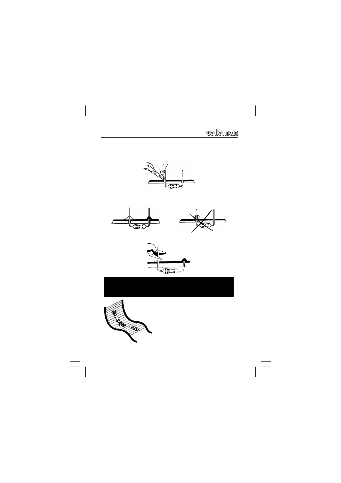
1.3 Soldering Hints :
Mount the component against the PCB surface and carefully solder the
leads
Make sure the solder joints are cone-shaped and shiny
Trim excess leads as close as possible to the solder joint
AXIAL COMPONENTS ARE TAPED IN THE CORRECT
MOUNTING SEQUENCE !
REMOVE THEM FROM THE TAPE
ONE AT A TIME !
4
Page 5
5%
4K7= ( 4 - 7 - 2 - B )
1%
4K7= ( 4 - 7 - 0 - 1 - 1 )
COLOR= 2… 5
C O D
E
KODE
COLOR= 2...5
KLEUR
CODIFI-
CATION
DES COU-
CODE
COLOUR
FARB
KODE
KODE
FARGE-
KODE
FARVE-
FÄRG
SCHEMA
VÄRI
KOODI
ORES
CODIGO
DE COL-
LEURS
I P E SF S DK N D GB F NL
CODIGO
DE CORES
CODICE
COLORE
C O D E
0 Nero Preto Negro Musta Svart Sort Sort Schwarz Black Noir Zwart 0
1 Marrone Castanho Marrón Ruskea Brun Brun Brun Braun Brown Brun Bruin 1
2 Rosso Encarnado Rojo Punainen Röd Rød Rød Rot Red Rouge Rood 2
3 Aranciato Laranja Naranjado Oranssi Orange Orange Orange Orange Orange Orange Oranje 3
4 Giallo Amarelo Amarillo Keltainen Gul Gul Gul Gelb Yellow Jaune Geel 4
5 Verde Verde Verde Vihreä Grön Grøn Grønn Grün Green Vert Groen 5
6 Blu Azul Azul Sininen Blå Blå Blå Blau Blue Bleu Blauw 6
7 Viola Violeta Morado Purppura Lila Violet Violet Violet Purple Violet Paars 7
8 Grigio Cinzento Gris Harmaa Grå Grå Grå Grau Grey Gris Grijs 8
9 Bianco Branco Blanco Valkoinen Vit Hvid Hvidt Weiss White Blanc Wit 9
A Argento Prateado Plata Hopea Silver Sølv Sølv Silber Silver Argent Zilver A
B Oro Dourado Oro Kulta Guld Guld Guldl Gold Gold Or Goud B
Page 6

Construction
R...
1. Jumper
q CH... : depending on the number of channels
q RX ‘∗’
‘∗’ATTENTION : In case you use light bulbs, Cold-Cathode
fluorescent lamps & “solid-state” relays mount for RX a jumper
wire, If using LED’s as output indication then mount for RX a
resistor appropriated to the value of the LED. See step 2.
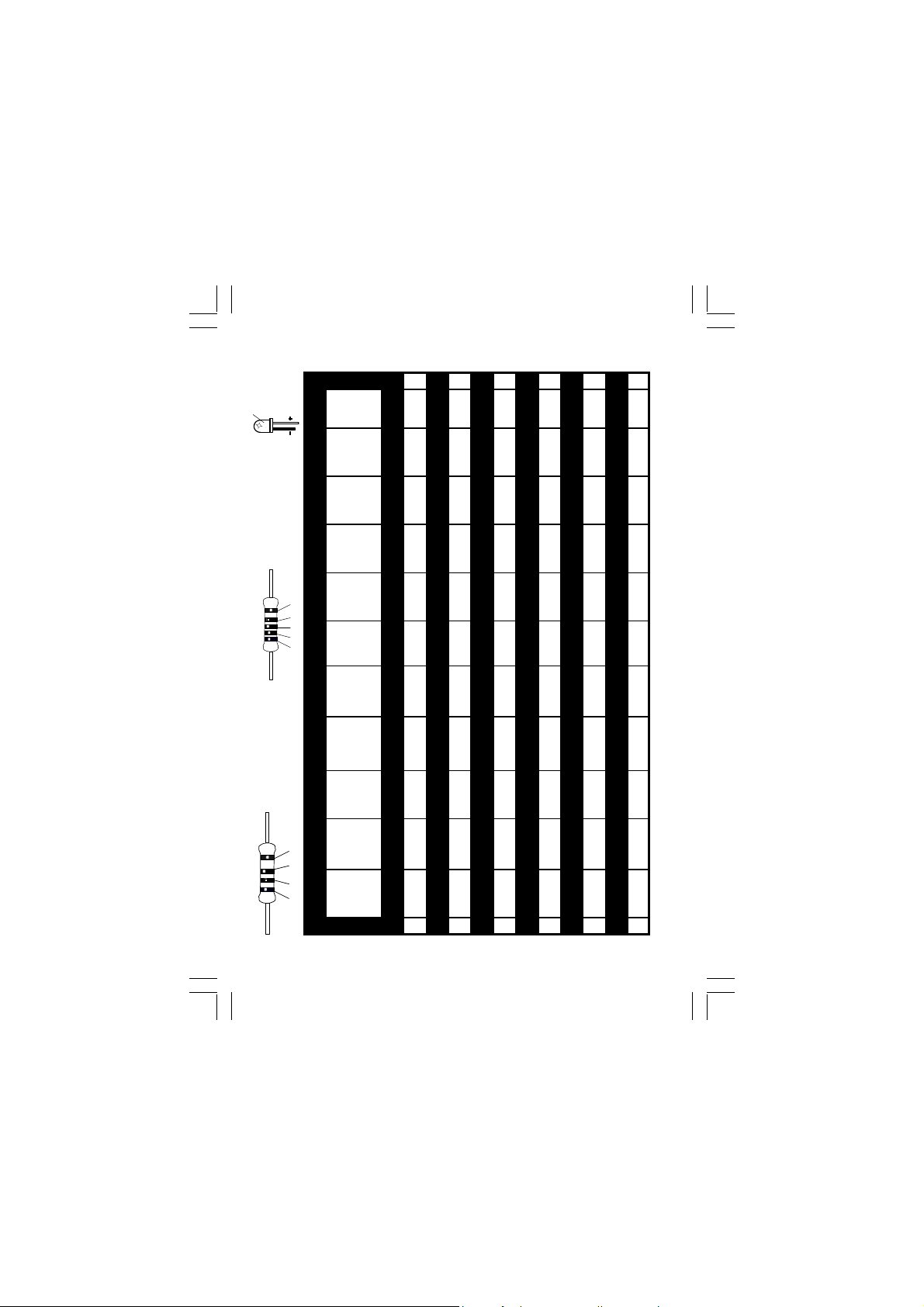
2. Resistors ‘RX’
q RX (for each output)
Type of LED
Standard (Red)
White
Yellow / Green
Blue
1K 820
470 330
1K 820
470 390
G These resistors are not supplied whit this kit!
6
Page 7

R...
Construction
3. Resistors
q R1 : 10K (1-0-3-B)
q R2 : 10K (1-0-3-B)
q R3 : 10K (1-0-3-B)
q R4 : 10K (1-0-3-B)
q R5 : 10K (1-0-3-B)
q R6 : 10K (1-0-3-B)
q R7 : 10K (1-0-3-B)
q R8 : 10K (1-0-3-B)
q R9 : 10K (1-0-3-B)
q R10 : 10K (1-0-3-B)
q R11 : 270 (2-7-1-B)
q R12 : 270 (2-7-1-B)
q R13 : 270 (2-7-1-B)
q R14 : 270 (2-7-1-B)
q R15 : 270 (2-7-1-B)
q R16 : 270 (2-7-1-B)
q R17 : 270 (2-7-1-B)
q R18 : 270 (2-7-1-B)
q R19 : 270 (2-7-1-B)
q R20 : 270 (2-7-1-B)
q R21 : 4K7 (4-7-2-B)
q R22 : 4K7 (4-7-2-B)
q R23 : 4K7 (4-7-2-B)
q R24 : 4K7 (4-7-2-B)
q R25 : 4K7 (4-7-2-B)
q R26 : 4K7 (4-7-2-B)
q R27 : 4K7 (4-7-2-B)
q R28 : 4K7 (4-7-2-B)
q R29 : 4K7 (4-7-2-B)
q R30 : 4K7 (4-7-2-B)
q R31 : 47 (4-7-0-B)
q R32 : 3K3 (3-3-2-B)
q R33 : 10K (1-0-3-B)
q R34 : 10K (1-0-3-B)
q R35 : 10K (1-0-3-B)
q R36 : 330 (3-3-1-B)
4. Diodes. Watch the
polarity !
CATHODE
D...
q D1 : 1N4007
q D2 : 1N4007
q D3 : 1N4007
q D4 : 1N4007
q D5 : 1N4007
q D6 : 1N4007
q D7 : 1N4007
q D8 : 1N4007
q D9 : 1N4007
q D10 : 1N4007
q D11 : 1N4007
q D12 : 1N5404
7
Page 8
Construction
C...
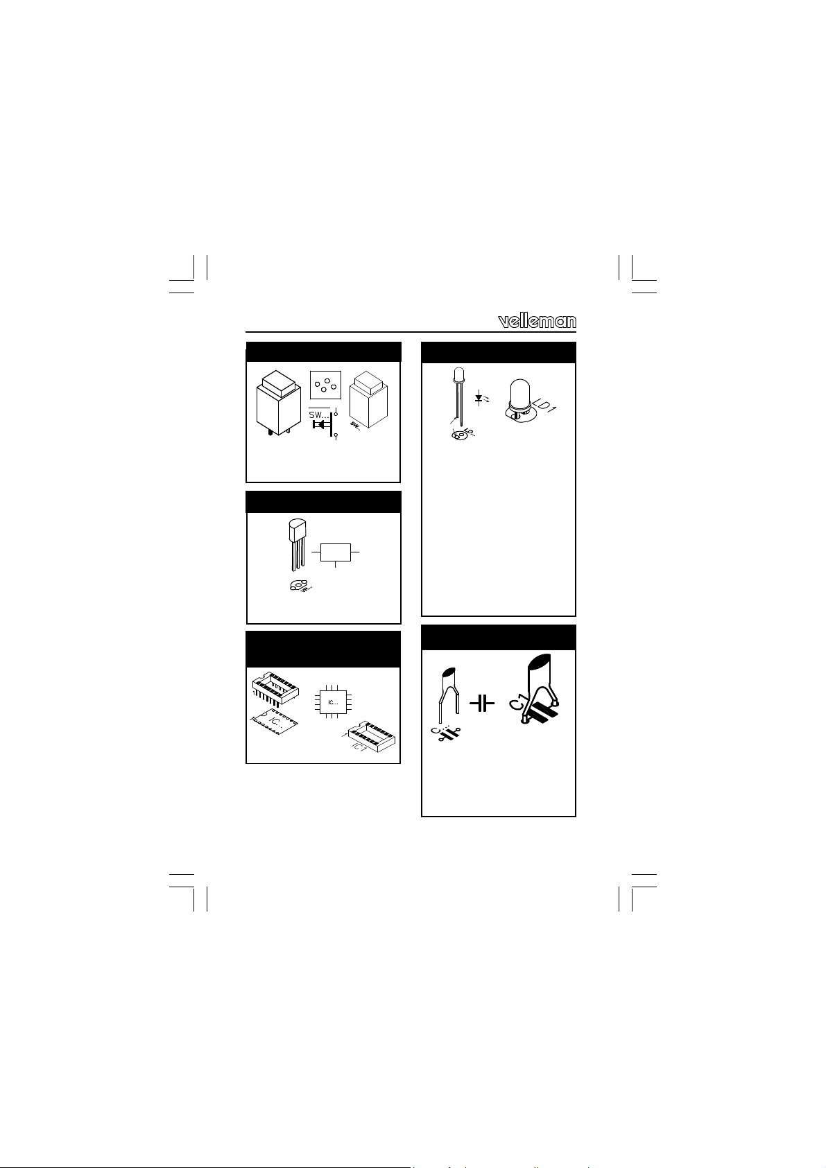
5. Pushbuttons.
q SW1 : S500
q SW2 : S500
6. Voltage Regulator.
VR...
q VR1: UA78L05
7. IC socket, Watch the
position of the notch!
q IC1 : 18P
8. LED. Watch the polarity !
COLOR= 2...5
LD...
CATHODE
q LD1 : 5mm Red
q LD2 : 5mm Red
q LD3 : 5mm Red
q LD4 : 5mm Red
q LD5 : 5mm Red
q LD6 : 5mm Red
q LD7 : 5mm Red
q LD8 : 5mm Red
q LD9 : 5mm Red
q LD10 : 5mm Red
q LD11 : 5mm Red
9.Ceramic Capacitors
q C2 : 100nF (104)
q C4 : 100nF (104)
q C6 : 100nF (104)
q C7 : 100pF (101)
8
Page 9

C...
Construction
10. Transistors.
q T1 : BC640
q T2 : BC640
q T3 : BC640
q T4 : BC640
q T5 : BC640
q T6 : BC640
q T7 : BC640
q T8 : BC640
q T9 : BC640
q T10 : BC640
q T11 : BC547B
q T12 : BC547B
q T13 : BC547B
q T14 : BC547B
q T15 : BC547B
q T16 : BC547B
q T17 : BC547B
q T18 : BC547B
q T19 : BC547B
q T20 : BC547B
11. Electrolytic capacitors.
Watch the polarity !
q C5 : 10µF
q C3 : 220µF
q C1 : 1000µF / 25V
12. Trim potentiometer
q RV1 : 100K
9
Page 10

Construction
13. Terminal block
connectors
SK10
...
...
SK1
SK1
q SK1 : CH1 (2p)
q SK2 : CH2 (2p)
q SK3 : CH3 (2p)
q SK4 : CH4 (2p)
q SK5 : CH5 (2p)
q SK6 : CH6 (2p)
q SK7 : CH7 (2p)
q SK8 : CH8 (2p)
q SK9 : CH9 (2p)
q SK10 : CH10 (2p)
q SK11 : 2p
SK10
14. Fuseholder + Fuse
F...
q F1 : 4A (slow)
15. IC, Check the
position of the notch !
q IC1: VK8044
Programmed PIC16C58B20
10
Page 11

16. Hook-up diagram
Hook-up diagram
HIGH
VOLTAGE !
Cold-cathode
fluorescent lamps
OR !
12V INPUT
12V bulb
400mA max.
12VDC / max 4A
12VDC/400mA
Inspect the complete assembly once more
before applying power to the unit !
Inverter FLPS
per channel
11
Page 12

Connection
17. Use
Connect this kit according to the wiring diagram. LED LD1 will light if the
operating voltage is correct. Take all necessary precautions to avoid
electroshocks when connecting cold-cathode fluorescent lamps : the
inverter ‘FLPS1’ uses a potentially life-th reatening voltage.
F This kit is available in various countries. Take care to use
an appropriate connection or adapter.
Selecting a light effect :
Push button SW1 ‘Effect select’ allows you to choose one of ten available programmes. Hold SW1 to see which effect is currently selected :
the LED of that effect will light. The light effect will start running when you
release SW1. Press SW1 momentarily to select the next light effect.
SW2 enables you to activate or deactivate all channels. Press SW1 to
restart the selected light effect.
Adjust the speed of the running light with RV1
F The connection cables should be equipped with an appropri-
ate strain relief when mounted in a movable housing.
Random light effect :
Hold SW2 pressed before connecting the power supply (the
other light patterns shall not work!).
Number of connected channels :
Mount a jumper wire on the spot that matches the amount of
light channels you would like to use. This will make some light
!
effects adjust to the number of channels used.
Example : Mount a jumper wire on 5 CH if you wish to use 5
light channels.
12
Page 13

18. PCB layout.
PCB
13
Page 14

Schematic diagram
SK1OUT1SK2OUT2SK4OUT4SK5OUT5SK3
O
U
T
3
S
K
6OU
T6SK7OU
T
7
S
K
8OUT8SK9OUT9SK1
0OUT10D11N400
7
GND
D
21N4007GNDD
31N
4007G
NDD41
N40
07G
N
D
GNDD51N40
0
7D6
1
N40
07G
N
DD7
1
N4007GNDD
81N4007
G
N
D
R
210KR310KR410KR
110KR510KR610KR71
0
K
R11270R
12270R13270
R14270R15270R1627
0
T11BC547LD1LED5RLGNDLD2
LED5RLL
D
3
LED5RLLD4LED5RLLD5LED5R
L
5
R
L
T12
BC5
47T13BC547T14BC54
7T1
5BC
5
4
7
GNDGNDGND
GND
VDD14
MCLR4
R214K
7R224
K7R234K
7R2
44K
7
GND
A
X.CH.SETU
P
RX1RX
2RX
3RX4RX5RX6RX7RX8RX9
1
0
T1BC640
T2B
C
6
40T3BC640T4BC640T5BC640T6BC
640T7BC64
0T8BC64
0
19. Schematic diagram.
"
R
L
E
R
W
5
1
1
O
D
D
E
P
"
L
L
6
0
3
3
D
R
3
N
G
6
0
B
R
/
T
N
I
n
6
0
C
0
1
D
1
N
C
I
G
µ
0
C51
D
N
G
5
0
O
L
8
1
7
A
R
I
V
U
n
4
0
0
C
1
7
0
µ
0
3
0
4
1
1
1
C
2
N
3
7
2
D
1
4
R
n
2
0
0
C
1
D
N
G
V
5
2
/
µ
0
1
0
C
0
1
D
N
G
4
0
2
4
1
5
D
N
D
1
N
G
W
O
L
1
S
F
D
A
N
4
G
C
1
D
1
V
K
2
S
1
+
4
K
3
D
N
G
D
N
G
D
N
G
0
R
1
3
K
3
0
1
R
K
1
2
3
0
3
V
K
0
R
3
1
R
D
E
E
P
S
T
C
E
F
F
E
14
X
R
D
D
N
N
G
G
7
7
0
0
0
0
0
4
9
4
1
0
0
N
D
N
D
4
4
1
6
C
B
9
T
8
K
0
R
1
7
0
8
0
1
7
1
7
2
R
2
R
L
R
5
8
7
6
D
L
D
N
G
5
7
2
K
4
R
0
1
9
8
7
3
4
2
1
B
B
B
B
R
R
R
R
2
3
A
A
R
R
1
2
D
D
D
D
E
L
E
L
L
L
7
7
4
4
7
6
5
1
C
T
B
6
7
2
K
R
4
3
2
1
1
1
1
7
6
5
B
B
B
R
R
R
T
U
N
I
O
K
K
L
L
C
C
/
/
1
2
C
C
S
S
O
O
5
6
1
1
8
5
1
1
C
T
T
B
D
D
N
N
G
G
7
8
7
7
2
2
K
K
R
4
R
4
H
H
H
H
H
C
C
C
C
C
2
3
4
5
1
-
-
-
-
-
2
3
4
5
1
J
J
J
J
J
7
8
1
1
0
1
A
A
R
R
RA4/T0CKI
3
VSS
5
B
8
5
C
6
1
C
I
P
0
2
0
5
W
S
S
D
N
0
1
G
0
W
5
S
S
T
C
E
L
E
S
T
C
E
F
F
E
F
p
7
0
C
0
1
D
N
G
1
6
C
B
0
1
T
0
K
K
9
1
0
0
R
R
1
1
0
0
9
0
7
2
1
7
2
R
2
R
L
R
5
D
E
L
7
4
5
C
B
D
N
G
H
C
6
-
6
J
L
L
R
R
5
5
0
1
9
D
D
E
E
D
D
L
L
L
L
7
7
4
4
5
5
0
9
C
C
2
1
T
B
T
B
D
N
G
9
7
2
0
7
K
3
R
4
K
R
4
0
1
J
.
.
.
.
1
H
J
C
H
H
H
n
0
o
C
C
1
C
-
r
8
9
7
-
-
0
-
e
1
8
9
7
p
J
J
J
J
m
u
j
a
t
u
p
M
e
s
a
e
l
5
K
3
P
0
R
1
D
N
G
D
N
G
Page 15

Page 16

VELLEMAN Components NV
Legen Heirweg 33
9890 Gavere
Belgium Europe
www.velleman.be
www.velleman-kit.com
Modifications and typographical errors reserved
© Velleman Components nv.
H8044IP - 2002 - ED1
16
 Loading...