

Page 1
Total solder points: 115
Difficulty level: beginner 1 2 3 4 5 advanced
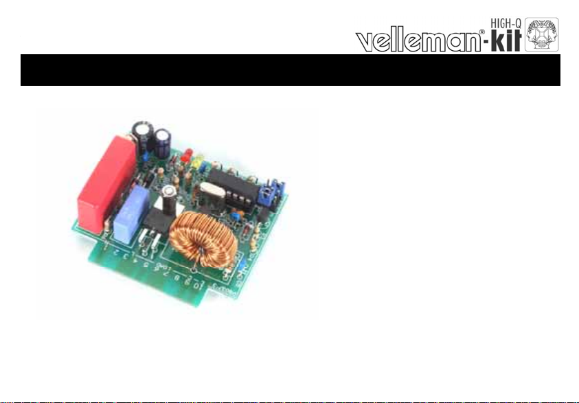
BUS DIMMER FOR HOME MODULAR LIGHT SYSTEM
K8037
e
s
u
r
o
f
e
l
u
d
o
m
”
N
I
-
G
U
L
P
“
h
h
t
i
w
m
e
m
o
m
e
t
s
y
s
r
a
l
u
d
o
6
0
0
8
K
s
t
h
g
i
l
.
ILLUSTRATED ASSEMBLY MANUAL H8037IP-1
1
Page 2

2
Page 3

Features & Specifications
This dimmer is a plug-in module for our K8006 home lighting system. Just like its predecessor K8007, it was
designed for the dimming of conventional incandescent lamps and halogen lighting. Not only is this kit easy
to operate with just one push button, it is also equipped with numerous safety features. With low-voltage
halogen lighting the transformation from mains voltage to 12V lamp voltage is to be achieved by means of a
wire-wound transformer. You can use both a toroidal and an encapsulated transformer. Most electronic transformers are incompatible with this dimmer.
Specifications:
Dimmer for our K8006 home lighting system.
Suitable for incandescent lamps, mains voltage halogen lighting and low voltage halogen lighting in combination with a
conventional (wire wound) transformer.
Easy push-button operation
A brief push toggles on/off, while continued pushing engages the dimming function
Non volatile memory for last light intensity setting.
Lots of safety features to protect lamp life e.g. “soft-start” function and automatic deactivation after 12 hours or after 20 min
of operation at insufficient light intensity...
Transformer prote ctio n in case of defe ct ive lig ht so urce s.
LED status indication.
Features:
Suppression of radio & TV interference according to EN55015.
Operating voltages: 110-125V or 230-240V AC (50/60Hz)
Max. load: 350 W/2 30V or 170W/115V
Max. phase shift with inductive load: 30°.
Dimming speed: +/- 5 sec.
PCB dimensions: 65 x 57 x 25mm.
3
Page 4
Assembly hints
0
.
0
0
0
1. Assembly (Skipping this can lead to troubles ! )
Ok, so we have your attention. These hints will help you to make this project successful. Read them carefully.
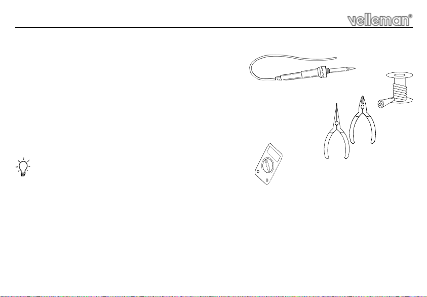
1.1 Make sure you have the right tools:
• A good quality soldering iron (25-40W) with a small tip.
• Wipe it often on a wet sponge o r c loth , to ke ep it c lean ; th en apply so lder to th e t ip, to g ive it a wet look. This is called ‘thinn ing’ an d w ill
protect the tip, an d enab les you t o make good conn ections. When so lder ro lls of f th e tip, it ne eds clean ing.
• Thin raisin-core solder. Do not use any flux or grease.
• A diagonal cutter to trim excess wires. To avoid in jury wh en cutting ex cess leads, ho ld the lead so th ey
cannot fly towards the eyes.
• Needle nose pliers, for bending leads, or to hold components in place.
• Small blade and Phillips screwdrivers. A basic range is fine.
For some projects, a basic multi-meter is required, or might be handy
1.2 Assembly Hints :
⇒ Make sure the skill level matches your experience, to avoid disappointments.
⇒ Follow the instructions carefully. Read and understand the entire step before you perform each operation.
⇒ Perform the assembly in the correct order as stated in this manual
⇒ Position all parts on the PCB (Printed Circuit Board) as shown on the drawings.
⇒ Values on the circuit diagram are subject to changes.
⇒ Values in this assembly guide are correct*
⇒ Use the check-boxes to mark your progress.
⇒ Please read the included information on safety and customer service
* Typographical inaccuracies excluded. Always look for poss ible last m inu te manu al updates, indicated as ‘NOTE ’ on a separate leaflet.
4
Page 5

1.3 Soldering Hints :
1- Mount the component against the PCB surface and carefully solder the leads
2- Make sure the solder joints are cone-shaped and shiny
3- Trim excess leads as close as possible to the solder joint
REMOVE THEM FROM THE TAPE ONE AT A TIME !
Assembly hints
AXIAL COMPONENTS ARE TAPED IN THE COR-
RECT MOUNTING SEQUENCE !
5
Page 6

Construction
LD...
CATHODE
CATHODE
1. Jumper
J : 5X
Make sure that the
jumpers are mounted
close to the PCB!
2. Diodes. Watch the polarity !
D1 : 1N4007
D2 : 1N4148
D3 : 1N4148
CATHODE
3. Zenerdiodes. Watch the
ZD1 : 12V0
ZD2 : 4V7
ZD3 : 4V7
ZD...
polarity !
CATHODE
6
4. Metal film resistor
R1 : 47 (4 - 7 - 0 - B - 9)
5. Resistor
D...
R2 : 390 (3 - 9 - 1 - B)
6. IC socket, watch the
position of the notch !
IC1 : 14P
R...
7. Capacitors.
C...
C1 : 100nF (104)
C2 : 100nF (104)
C3 : 10nF (103)
R...
C4 : 10nF (103)
C5 : 10nF (103)
C6 : 15pF (15)
C7 : 15pF (15)
8. LEDs. Watch the polarity!
LD1 : Red
LD2 : Yellow
Page 7

Construction & connection
9. Transistors.
T1 : BC547B
T2 : BC547B
10. Pin headers
JP1 : 3 pins
JP2 : 3 pins
JP3 : 3 pins
1 2 3
11. Vertical resistors
R3 : 100K (1 - 0 - 4 - B)
R4 : 470K (4 - 7 - 4 - B - 9)
R5 : 470K (4 - 7 - 4 - B - 9)
R6 : 1M (1 - 0 - 5 - B - 9)
R7 : 100K (1 - 0 - 4 - B)
R8 : 1K5 (1 - 5 - 2 - B)
R9 : 1K5 (1 - 5 - 2 - B)
R10 : 220 (2 - 2 - 1 - B - 9)
R11 : 3K9 (3 - 9 - 2 - B)
R12 : 3K9 (3 - 9 - 2 - B)
R13 : 3K9 (3 - 9 - 2 - B)
JP3
R4 … R6 & R10 are metal film
JP2
JP1
resistors.
R...
12. Capacitor
C10 : 100nF/250VAC
13. Electrolytic Capacitors.
Watch the polarity !
C8 : 100µF
C9 : 220µF
C...
14. 1W resistors
R14 : 220 (2 - 2 - 1 - B)
R...
7
Page 8

Construction
15. Quartz crystal
X...
X1 : 10MHz
16. Triac
TR1 : TIC225M
METAL DISTANCE BOLT
TRIAC
M3 NUT
M3 LOCK WASHER
M3 BOLT
8
17. Capacitor
Choose operating voltage :
For 110 - 125VAC :
C11 : 1µF / 250V
For 220 - 240VAC :
C11 : 0,47µF / 630V
18. Coil.
L1 : 1mH / 2,5A
19. IC, Check the position of
the notch!
IC1 : VK8037
programmed PIC16 F6 30 - I/P
CHECK THOROUGHLY ALL
THE COMPO NENTS FOR MISS
MOUNTING, INCLUDING SOL-
DERING ERRORS.
Page 9

Installation & use
20. Installation & use
Cut off the mains voltage of the K8006 (deactivate the main fuse of your switch box).
Mount the jumpers in locations JP1,2, 3. (see fig. 1.0) to select the settings (see page 12).
LD1
(Red)
LD2
(Yellow)
1 2 3
JP3
JP1 : Memory function
JP2 : Safe min. Luminous itensity.
JP2
JP3 : Deactivation timer.
JP1
Place the K8037 module into a free connector.
Connect a load suitable for the specifications of this module !
9
Page 10

Installation & use
You can now activate your K8006
When you start up your K8037, LD1 & LD2 will flash together for a couple of seconds until the self-test is
completed. The indication LEDs display any irregularity the CPU may discover (read "LED indication in case of
error" below). Following the self-test, LD2 will flash once when the net frequency is 50Hz or twice for 60Hz.
The module is now operational.
Press an arbitrary button momentarily to activate or deactivate the light source or hold the butt on to adjust
the luminous intensity.
LED indications in case of normal operation:
LD2 (yellow LED):
Flashes once every 5 seconds when the module is in standby mode (lamp OFF).
Flashes slowly (2x/sec) when the lamp is burning, but not at full luminous intensity.
Stays ON when max. luminous intensity has been reached.
Flashes very quickly (10x/sec) while the luminous intens ity is bei ng adjusted.
LD1 (red LED):
Flashes slowly together with LD2 (yellow LED) if the luminous intensity is too low. This only happens with
JP3 in the ‘2-3’ position.
10
Page 11

Installation & use
LED indications in case of error:
When the CPU detects an error, LD1 (red) can provide an indication as to the nature of the problem. LD2
(yellow) will then remain lit continuously, whereas LD1 (red) will repeatedly flash a number of times:
We advise you to briefly interrupt the supply voltage and evaluate the situation. It is possible to restart the
module without interrupting the voltage: hold the operation button for at least 10 seconds (until both LEDs
are extinguished).
Flashes
LD1
1
2
3 Triac triggering timeout
4 Phase shift is too great
Timeout in the positive alternation of the
mains voltage
Timeout in the negative alternation of the
mains voltage
Error Possible cause / solu tio n
error in voltage zero-crossing circuit (T1, ...)
error in voltage zero-crossing circuit (T1, ...)
- Triac defective ?
- Light source defective ?
- T2 defective ?
- Load doesn't conform to specifications ?
- Load behaves too inductively ?
- No load connected ?
- No load on transformer (because of defective lamp ?)
- Load not conform ?
11
Page 12

Jumper selection
21. Jumper selection
The settings of the dimmer module are determined by placing a shunt (=jumper) over pins 1-2 or 2-3 of JP1,
2 and 3 (see figure 1.0). The operation of the device becomes unstable if the jumpers are not mounted.
JP1 – Memory function:
The last used luminous intensity is stored in the memory if this function is activated.
JP2 – Safe min. luminous intensity :
This function is designed to make sure a lamp doesn't burn at too low a luminous intensity for too long. This
function offers two distinct advantages: first of all, the life of a halogen bulb is not shortened unnecessarily
because it's working at too low a temperature. Furthermore, it doesn't really matter if a lamp escapes your notice
because of its limited luminous intensity. The lamp will be extinguished automatically after a certain time.
12
1-2: Memory function is deactivated.
or
2-3: Memory function is activated.
1-2: This function is deactivated.
or
2-3: This function is activated.
Page 13

Jumper selection
JP3 – Deactivation timer:
Lamps are automatically deactivated after ± 12 hours of continuous use when this function is activated:
1-2: Deactivation timer is deactivated.
or
2-3: Deactivation timer is activated.
The “TP” connection on the print is only used by the people in our technical department.
13
Page 14

PCB
22. PCB layout.
14
Page 15

23. Diagram
Diagram
15
Page 16

VELLEMAN Components NV
www.velleman-kit.com
Modifications and typographical errors reserved
© Velleman Components nv.
H8037IP - 2004 - ED1
16
Legen Heirweg 33
9890 Gavere
Belgium Europe
www.velleman.be
5 410329 334796
 Loading...