

Page 1

Total solder points: 71
Difficulty level:
beginner 1o 2o 3o 4o 5þ advanced
Slow ON/OFF DIMMER
for modular light system
K8029
Features and specifications :
þ Microprocessor controlled.
þ Dual mode operation:
Mode 1 : Slow on / Slow off dimmer with two inde pendent and programmable delays. Dimming
direction changes with each keypress. Manual level
control is possible. This mode also simulates a
‘regular’ dimmer.
Mode 2 : Light is turned on at full power for a pro grammable time, after which it slowly fades to zero,
also during a programmable time.
þ For use with the Velleman home modular light system
K8006.
þ Two programmable delays ranging from 1s to 1h.
þ No memory loss in case of power failure.
þ 'soft-start' function that prolong the life of the bulbs.
þ AC power : 110-125 or 220-240VAC 50/60Hz.
þ Max. load : 1,3A (150W/120V – 300W/230V).
þ Dimensions : 67x57x25mm (2.7”x2.3”x1”).
Not suited for use with low voltage halogen
lighting or electronic transformers.
NOISE
SUPPRESSED
ACCORDING TO
EN55015
ILLUSTRATED ASSEMBLY MANUAL H8029IP-1
Page 2
VELLEMAN KIT NV
Legen Heirweg 33
9890 Gavere
Belgium
http://www.velleman.be
Page 3
0.000
Assembly hints
1. Assembly (Skipping this can lead to troubles ! )
Ok, so we have your attention. These hints will help you to make this project successful. Read them carefully.
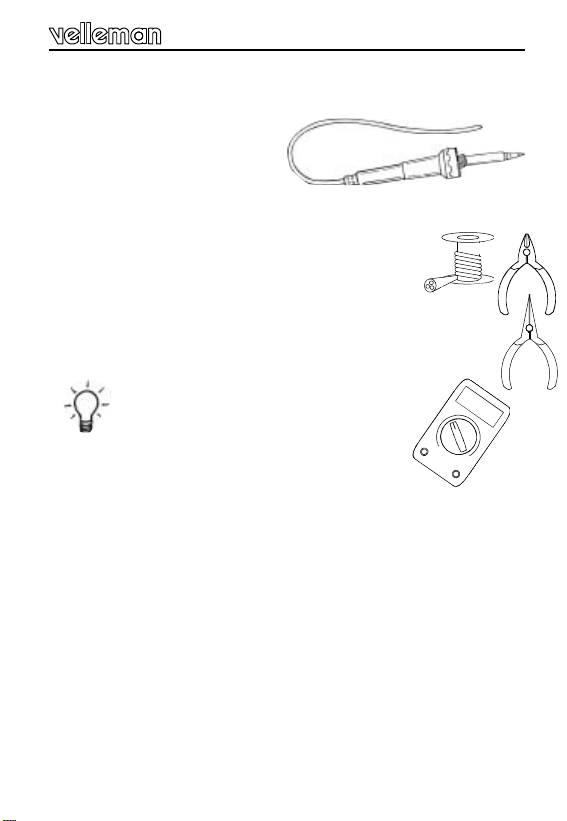
1.1 Make sure you have the right tools:
• A good quality soldering iron (2540W) with a small tip.
• Wipe it often on a wet sponge or cloth, to keep it clean; then apply solder to the
tip, to give it a wet look. This is called ‘thinning’ and will protect the tip, and enables you to make good connections. When solder rolls off the
tip, it needs cleaning.
• Thin raisin-core solder. Do not use any flux or grease.
• A diagonal cutter to trim excess wires. To avoid injury when
excess leads, hold the lead so they cannot fly towards the eyes.
• Needle nose pliers, for bending leads, or to hold components in place.
• Small blade and phillips screwdrivers. A basic range is fine.
For some projects, a basic multi-meter is required, or
might be handy
1.2 Assembly Hints :
⇒ Make sure the skill level matches your experience, to avoid
pointments.
cutting
disap-
⇒ Follow the instructions carefully. Read and understand the entire step before you
perform each operation.
⇒ Perform the assembly in the correct order as stated in this manual
⇒ Position all parts on the PCB (Printed Circuit Board) as shown on the drawings.
⇒ Values on the circuit diagram are subject to changes.
⇒ Values in this assembly guide are correct*
⇒ Use the check-boxes to mark your progress.
⇒ Please read the included information on safety and customer service
* Typographical inaccuracies excluded. Always look for possible last minute manual
updates, indicated as ‘NOTE’ on a separate leaflet.
3
Page 4
Assembly hints
COLOR= 2… 5
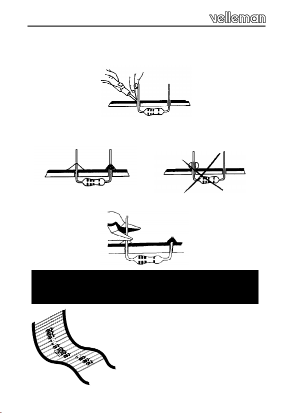
1.3 Soldering Hints :
Mount the component against the PCB surface and carefully solder the
leads
Make sure the solder joints are cone-shaped and shiny
Trim excess leads as close as possible to the solder joint
AXIAL COMPONENTS ARE TAPED IN THE CORRECT
MOUNTING SEQUENCE !
REMOVE THEM FROM THE TAPE
ONE AT A TIME !
4
Page 5
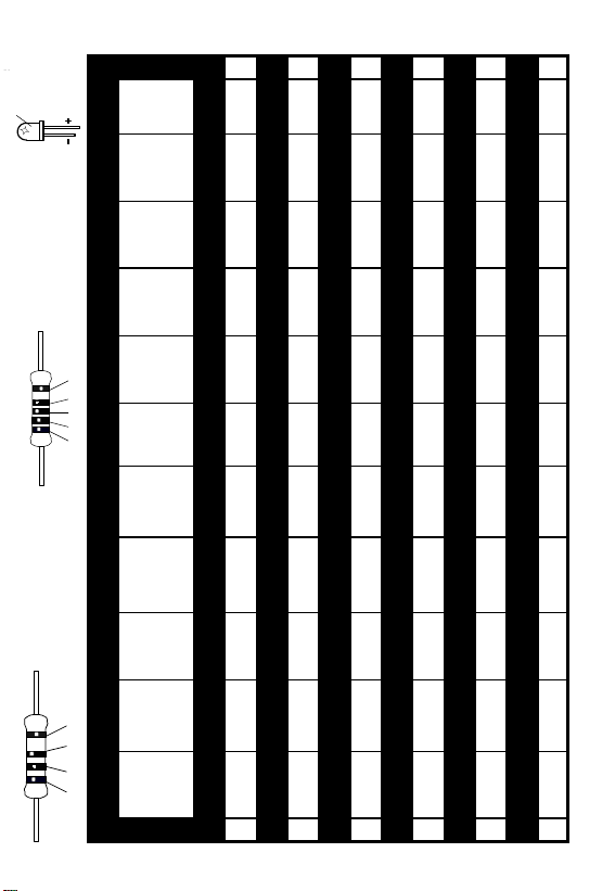
5%
4K7= ( 4 - 7 - 2 - B )
1%
4K7= ( 4 - 7 - 0 - 1 - 1 )
COLOR= 2… 5
C O D
E
KODE
COLOR= 2...5
KLEUR
CODIFI-
CATION
CODE
COLOUR
FARB
KODE
KODE
FARGE-
KODE
FARVE-
FÄRG
SCHEMA
VÄRI
KOODI
DES COU-
LEURS
DE
CODIGO
COLORES
I P E SF S DK N D GB F NL
CODIGO
DE CORES
CODICE
COLORE
C O D
E
0 Nero Preto Negro Musta Svart Sort Sort Schwarz Black Noir Zwart 0
1 Marrone Castanho Marrón Ruskea Brun Brun Brun Braun Brown Brun Bruin 1
2 Rosso Encarnado Rojo Punainen Röd Rød Rød Rot Red Rouge Rood 2
3 Aranciato Laranja Naranjado Oranssi Orange Orange Orange Orange Orange Orange Oranje 3
4 Giallo Amarelo Amarillo Keltainen Gul Gul Gul Gelb Yellow Jaune Geel 4
5 Verde Verde Verde Vihreä Grön Grøn Grønn Grün Green Vert Groen 5
6 Blu Azul Azul Sininen Blå Blå Blå Blau Blue Blue Blauw 6
7 Viola Violeta Morado Purppura Lila Violet Violet Violet Purple Violet Paars 7
8 Grigio Cinzento Gris Harmaa Grå Grå Grå Grau Grey Gris Grijs 8
9 Bianco Branco Blanco Valkoinen Vit Hvid Hvidt Weiss White Blanc Wit 9
A Argento Prateado Plata Hopea Silver Sølv Sølv Silber Silver Argent Zilver A
B Oro Dourado Oro Kulta Guld Guld Guldl Gold Gold Or Goud B
Page 6

Construction
1. Diodes.
(Watch the polarity)
CATHODE
D...
q D1 : 1N4148
q D2 : 1N4148
q D3 : 1N4007
2. Resistors.
R...
q R1: 47K (4-7-3-B)
q R2: 470K (4-7-4-B)
q R3: 470K (4-7-4-B)
q R4: 4E7 (4-7-B-B)
q R5: 10K (1-0-3-B)
q R6: 10K (1-0-3-B)
q R7: 330 (3-3-1-B)
q R8: 220K (2-2-4-B-9)
q R9: 220K (2-2-4-B-9)
q R10: 220 (2-2-1-B-9)
q R11: 27K (2-7-3-B-9)
q R12: 27K (2-7-3-B-9)
R...
Mount
R13
Vertical !
q R13: 330 (3-3-1-B)
3. Zener diode.
(Watch the polarity)
CATHODE
ZD...
q ZD1 : 5V6 / 1.3W
4. IC socket.
q IC1 : 8P
6
Page 7

Construction
5. DIP switch.
q SW1 : DS-2
SW...
1
6. Capacitors.
q C1 : 10nF (103)
q C2 : 100nF (104)
q C4 : 100nF/250V~
Check operating voltage
q For 220/240V~
C5 : 470nF/630V
q For 110/125V~
C5 : 1µF/250V
7. Electrolytic
capacitor.
(Watch the polarity)
C...
q C3 : 470µF
8. Transistor.
q T1 : BC547B
7
Page 8

Construction
9. LED’s.
COLOUR=2...5
CATHODE
CATHODE
LD...
q LD1: 3mm Red (2)
q LD2: 3mm Yellow (4)
10. Triac.
q TR1 : TIC206M or Eq.
11. Coil.
L...
q L1 : 1mH
12. IC (Check the position
of the notch !).
q IC1 : VK8029
= programmed µC:
PIC12CE518 or Eq.
8
Page 9

13. PCB layout & DIP switch setting.
1
2
1
2
1
2
1
2
ON
Slow-ON / Slow-OFF mode (1).
SW1 SW1
ON
Timer mode (2).
ON
SW1
ON
SW1
Learn mode (3).
Restore factory defaults (4).
9
Page 10

14. Use & programme this module.
Time.
T1.
T2.
Slow ON time
HOLD button: manual change
and hold brightness.
Time.
T1.
T2.
HOLD button: Switch OFF.
Brightness.
100%
50%
Brightness.
100%
50%
Fig. A - Mode 1:
Slow ON / OFF
0%
Slow OFF time
Fig. B - Mode 2:
TIMER mode.
0%
Press
button here.
10
ON time
at full brightness.
Slow OFF time
Page 11

CONNECTION & TEST: (*x: See page 9)
Always switch off the mains voltage from the K8006
bus card before:
- Plugging in or removing this module.
- Changing the operating mode. (If the K8029 is
being used, changing the operating mode has no
effect and is very dangerous!)
-Insert the K8029 into a free slot of a K8006 bus card.
-Connect a light bulb to the relevant output of the bus
card.
-Set both switches of the DIP switch SW1 to OFF (*1).
-Now switch on the voltage of the K8006 bus card, LD2
(yellow) will light up to indicate the good operation of the
microcontroller.
-The dimmer is now in the ‘slowly on and off’ state - the
factory programmed delay times are 3 minutes each.
The times can always be quickly restored,
(see ‘restoring factory settings’).
-See also page 10 (Fig A & B) of the illustrated assembly
plan for a graphic presentation of the operation.
PROGRAMMING:
The factory settings can be overwritten with your own
delay-time settings, which will be called the 1st time and
the 2nd time. Follow the procedure below for this:
Programming the 1st time (t1): (The slow ON time / delay
time in the step mode.)
1) Place the kit in the programming state using the DIP
switch SW1 (*3).
11
Page 12

2) Now switch the mains voltage on, the light and LD1 will
now burn at 2/3 intensity.
3) Briefly press the pushbutton, LD2 (yellow) will now light
up. The time registration starts now.
4) Wait until the desired time has been reached. (This
can be from 1 second to approx. 70 min. The clock will
stop automatically when the maximum registration time
has been exceeded.)
5) Briefly press the pushbutton again. The registration
clock will now stop.
-LD2 (yellow) will flash for a maximum of 5 seconds.
During this period, you have to press the pushbutton
again in order to save the registered time to memory.
When confirmed, LD1 (red) and LD2 (yellow) will flash
on 2x as an indication. If the pushbutton is not pressed
within the above 5 seconds, the time stored in the
memory will NOT be overwritten. This can be done if
only the 2nd time is to be adjusted.
Programming the 2nd time (t2): (The slow OFF time.)
-After programming the 1st time, the 2nd time automatically
follows. The light will now come on at 1/3 intensity.
-Now follow the same procedure as with the 1st time, from
point 3 onwards.
12
Page 13

Both LED’s go out at the end of the complete procedure.
Now switch off the voltage and select the operating mode
using DIP switch SW1 (slow ON/OFF or step mode).
Only switch the voltage back on after that!
Extra functions:
In the 2 different operating modes keeping the pushbutton pressed in (for more than 1 second) calls up an extra
function:
-With MODE1: The light intensity can be manually
changed here without difficulty. When the button is released the light intensity at that point in time will be preserved. This kit can thus be used as a normal hand operated dimmer. At the end of one dimming operation, the
button has to be released to reverse the dimming sense
(bright to dark or dark to bright), so that it is easy to turn
the light off or on at maximum light intensity.
-With MODE2: Keep the pushbutton pressed in for more
than 1 second during the time lapse or dimming cycle.
The light will then go out immediately.
Pressing it briefly restarts the entire cycle.
13
Page 14

Restore factory settings:
The standard factory settings for the delay times can be
restored by setting switch 1 & 2 of the DIP switch to
‘ON’ (*4). If the voltage is switched on to the kit in this
state then LD2 (yellow) will flash. After that keep the
pushbutton pressed in until both LD1 and LD2 flash. The
standard times of 3 minutes are now again stored in
memory. Switch the voltage off and select an operating
mode using DIP switch SW1 (slow ON/OFF or step
mode).
14
Page 15

15. Schematic diagram.
15
Page 16

VELLEMAN KIT NV
Legen Heirweg 33
9890 Gavere
Belgium Europe
Info ?: http://www.velleman.be
Questions ?: support@velleman.be
Modifications and typographical errors reserved
© Velleman Kit nv
H8029IP - 2000 - ED1
 Loading...