

Page 1
Total solder points: 29
Difficulty level: beginner 1 2 3 4 5 advanced
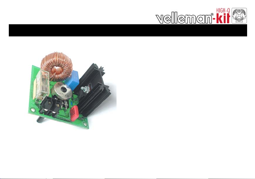
3,5A SUPPRESSED DIMMER
K8026
t
n
e
c
s
e
d
n
a
c
n
m
m
i
D
t
h
g
i
l
ILLUSTRATED ASSEMBLY MANUAL H8026IP-1
a
s
b
l
u
b
l
o
c
d
n
m
r
o
t
c
e
l
i
r
o
f
r
e
s
r
o
t
o
Page 2

Page 3

Features:
Dimmer for incandescent lightbulbs and collector motors.
protected against induction voltage peaks.
Suppressed according to EN55015.
Specifications:
AC power : 110-125 or 220-240VAC 50/60Hz.
Max. load : 3.5A (750W/220V; 375W/110V).
Dimensions: 60x60x40 mm (2.4”x2.4”x1.6”).
Features & Specifications
3
Page 4
Assembly hints
0
.
0
0
0
1. Assembly (Skipping this can lead to troubles ! )
Ok, so we have your attention. These hints will help you to make this project successful. Read them carefully.
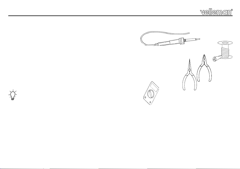
1.1 Make sure you have the right tools:
• A good quality soldering iron (25-40W) with a small tip.
• Wipe it often on a wet sponge o r c loth , to ke ep it c lean ; th en apply so lder to th e t ip, to g ive it a wet look. This is called ‘thinn ing’ an d w ill
protect the tip, an d enab les you t o make good conn ections. When so lder ro lls of f th e tip, it ne eds clean ing.
• Thin raisin-core solder. Do not use any flux or grease.
• A diagonal cutter to trim excess wires. To avoid in jury wh en cutting ex cess leads, ho ld the lead so th ey
cannot fly towards the eyes.
• Needle nose pliers, for bending leads, or to hold components in place.
• Small blade and Phillips screwdrivers. A basic range is fine.
For some projects, a basic multi-meter is required, or might be handy
1.2 Assembly Hints :
⇒ Make sure the skill level matches your experience, to avoid disappointments.
⇒ Follow the instructions carefully. Read and understand the entire step before you perform each operation.
⇒ Perform the assembly in the correct order as stated in this manual
⇒ Position all parts on the PCB (Printed Circuit Board) as shown on the drawings.
⇒ Values on the circuit diagram are subject to changes.
⇒ Values in this assembly guide are correct*
⇒ Use the check-boxes to mark your progress.
⇒ Please read the included information on safety and customer service
* Typographical inaccuracies excluded. Always look for poss ible last m inu te manu al updates, indicated as ‘NOTE ’ on a separate leaflet.
4
Page 5

Assembly hints
1.3 Soldering Hints :
1- Mount the component against the PCB surface and carefully solder the leads
2- Make sure the solder joints are cone-shaped and shiny
3- Trim excess leads as close as possible to the solder joint
REMOVE THEM FROM THE TAPE ONE AT A TIME !
AXIAL COMPONENTS ARE TAPED IN THE
CORRECT MOUNTING SEQUENCE !
You will find the colour code for the resistances and the LEDs in the HALG
(general manual) and on our website: http://www.velleman.be/common/service.aspx
5
Page 6

Construction
1. Diac.
D1 : D0200 or eq.
2. Resistor
R1 : 5K6 (5 - 6 - 2 - B)
FOR 110/125V ONLY :
R2 : 220K (2 - 2 - 4 - B)
R...
6
3. Potentiometer
RV1
HIGH
VOLTAGE
TR1
C2
R
1
L1
RV1 : 470K
Use supplied jumper wire to
connect as shown.
P8026'1
1
D
C1
RV1
R2
VELLEMAN
LN
A
L
D
O
SK1
F1
4A
SLOW
Jumper wire
4. Capacitors
C1 : 100nF (104)
C2 : 100nF / 250VAC
5. Terminal block
SK1
Page 7

Construction
6. Fuse holder + fuse
F1 (4A T)
7. Coil
F...
L...
L1 : 1,5mH / 1KHz. - 4A
8. Triac
10mm
M3 BOLT
TR1 : TIC225M or eq.
M3
NUT
Important : Put an extra layer
of solder on all pre-thinned
PCB tracks, to improve their
current handling capabilities.
7
Page 8

Hook-up
9. Hook-up example
8
!
380W/110V
750W/240V
MAX
AC POWER
WARNING : All parts carry
lethal voltages!
Do not touch while operating.
Use an isolated enclosure
knob.
Page 9

10. Schematic diagram.
60W ... 750W @ 230VAC
30W ... 400W @ 120VAC
LOAD
N
LOAD
AC POWER
L
L
SK1
F1
4A SLOW
R1
5K6
Schematic diagram
L1
220K @ 120V
R2
C1
100n
RV1
470K lin
D1
D0200YR
C2
100nF/250VAC
TR1
TIC225M
9
Page 10

PCB
11. PCB
10
F1
4A
SLOW
N
SK1
L1
1
R
L
D
A
O
L
RV1
R2
VELLEMAN
C2
TR1
C1
VOLTAGE
1
D
P8026'1
HIGH
Page 11

Page 12

VELLEMAN Components NV
www.velleman-kit.com
Modifications and typographical errors reserved
© Velleman Components nv.
H8026IP - 2004 - ED1
Legen Heirweg 33
9890 Gavere
Belgium Europe
www.velleman.be
5 410329 290986
 Loading...