

Page 1
Total solder points: 57
Difficulty level: beginner 1 2 3 4 5 advanced
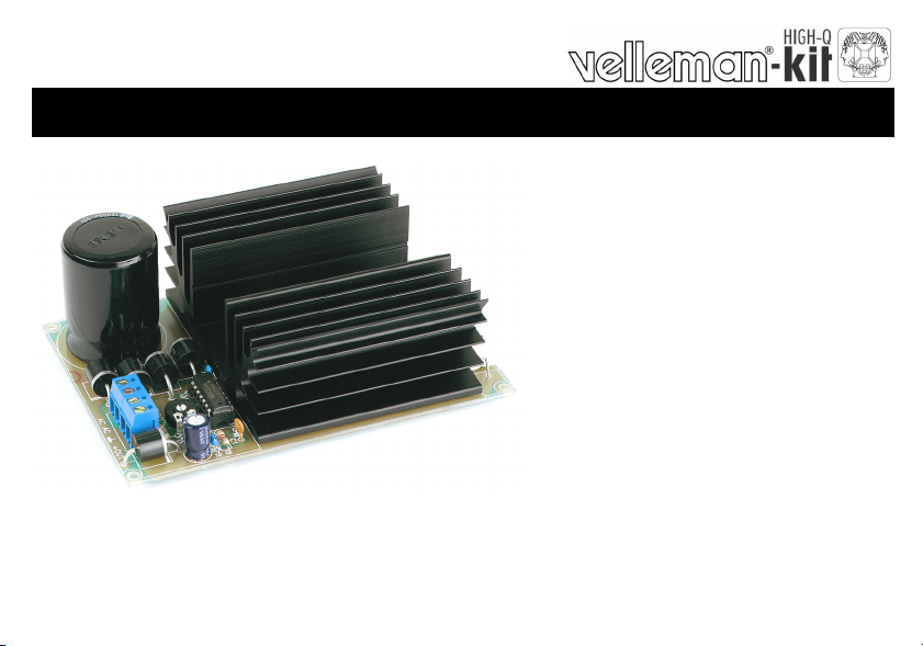
3 TO 30VDC / 3A POWER SUPPLY
K7203
d
e
s
a
b
,
s
t
i
k
r
u
o
l
l
a
o
p
A
ILLUSTRATED ASSEMBLY MANUAL H7203IP-1
s
a
n
o
e
s
i
l
i
b
a
t
v
C
D
d
p
u
s
r
e
w
o
e
g
a
t
l
o
r
fo
y
l
p
.
V
0
3
f
Page 2

Features
This kit is meant as an auxiliary or as a permanent power supply for all common Velleman kits based on a
stabilized DC voltage between 3 and 30V provided that the consumption does not exceed 3A.
Of course this power supply unit can be used for other purposes, as long as the maximum specifications are
taken into account.
Technical data :
Short circuit protected
Overload protected
Heatsink included
Output voltage: adjustable 3 to 30V stabilized.
Output current: max. 3A
Output ripple voltage: 0.5mV.
Input: 9 to 30V transformer, depending on the desired output
Dimensions (LxWxH): 130x91x50mm
Transformer not included
2
Page 3
Assembly hints
0
.
0
0
0
1. Assembly (Skipping this can lead to troubles ! )
Ok, so we have your attention. These hints will help you to make this project successful. Read them carefully.
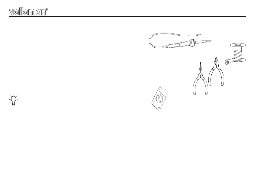
1.1 Make sure you have the right tools:
• A good quality soldering iron (25-40W) with a small tip.
• Wipe it often on a wet sponge or cloth, to keep it clean; then apply solder to the tip, to give it a wet look. This is called ‘thinning’ and will
protect the tip, and enables you to make good connections. W hen solder rolls off the tip, it needs cleaning.
• Thin raisin-core solder. Do not use any flux or grease.
• A diagonal cutter to trim excess wires. To avoid injury when cutting excess leads, hold the lead so they
cannot fly towards the eyes.
• Needle nose pliers, for bending leads, or to hold components in place.
• Small blade and Phillips screwdrivers. A basic range is fine.
For some projects, a basic multi-meter is required, or might be handy
1.2 Assembly Hints :
⇒ Make sure the skill level matches your experience, to avoid disappointments.
⇒ Follow the instructions carefully. Read and understand the entire step before you perform each operation.
⇒ Perform the assembly in the correct order as stated in this manual
⇒ Position all parts on the PCB (Printed Circuit Board) as shown on the drawings.
⇒ Values on the circuit diagram are subject to changes.
⇒ Values in this assembly guide are correct*
⇒ Use the check-boxes to mark your progress.
⇒ Please read the included information on safety and customer service
* Typographical inaccuracies excluded. Always look for possible last minute manual updates, indicated as ‘NOTE’ on a separate leaflet.
3
Page 4
Assembly hints
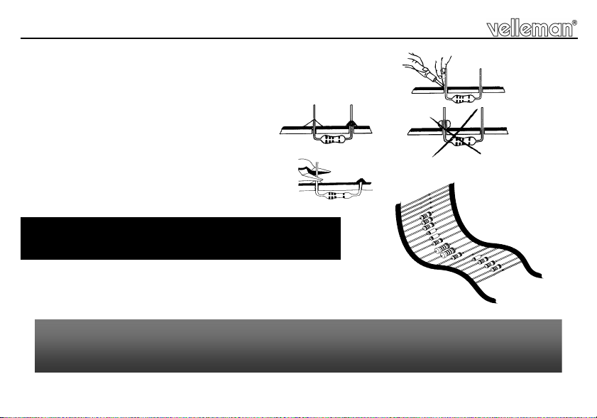
1.3 Soldering Hints :
1- Mount the component against the PCB surface and carefully solder the leads
2- Make sure the solder joints are cone-shaped and shiny
3- Trim excess leads as close as possible to the solder joint
AXIAL COMPONENTS ARE TAPED IN THE CORRECT
MOUNTING SEQUENCE !
REMOVE THEM FROM THE TAPE ONE AT A TIME !
You will find the colour code for the resistances and the LEDs in the HALG
(general manual) and on our website: http://www.velleman.be/common/service.aspx
4
Page 5

Construction
RV1
D.
CATHODE
1. Resistors
R1 : 8K2 (8 - 2 - 2 - B)
(Uout = output voltage)
R2
Uout 3...8V : 5K6 (5 - 6 - 2 - B)
Uout 8...30V : 2K2 (2 - 2 - 2 - B)
R3 : 680 (6 - 8 - 1 - B)
R4 : 1K (1 - 0 - 2 - B)
R5 : 82K (8 - 2 - 3 - B)
R...
2. IC sockets, Watch the
position of the notch !
IC1 : 14P
3. Capacitors.
C...
C1 : 470pF (471)
C2 : 100nF (104)
C3 : 100nF (104)
4. Resistor trimmer
RV1 : 10K
5. Diodes. Watch the polarity!
D1 : 6A2 or 6A6
D2 : 6A2
D3 : 6A2
6A6
D4 : 6A2
D5 : 6A2
D6 : 6A2
or 6A6
or
or 6A6
or 6A6
or 6A6
6. 5W resistor.
R6 : 0.18E
R...
2mm
7. Screw connectors
J1 : 2 x 2p
8. Electrolytic Capacitor.
Watch the polarity !
C4 : 100µF
C5 : 10.000µF
C...
5
Page 6

Construction
9. Power transistor
T1 : MJ3001 or 2N6284G
Apply some thermo-conducting
pasta to the bottom side of the
transistor and mount it on the
PCB simultaneously with the
cooling profile following the
instructions in the figure 1.0.
PCB
M3 NUT
LOCK WASHER
TRANSISTOR
HEATSINK
10. IC. Watch the position of
the notch!
IC1 : UA723D
Fig 1.0
6
M3 BOLT
Page 7

Assembly into a housing
11. Assembly into a housing
Depending on the transformer used, one may chose one of two housings with the following reference nr. for
ordering: L750 or L760.
If the circuit is to be integrated into another housing, it must be provided with ventilation holes (one may
make these holes oneself), necessary for the release of the heat developed.
If a metal housing is used, it must be earthed for security purposes.
Make sure the cooling body does not touch the housing. This might cause a short circuit.
When mounting a toroidal transformer, it must be seen to that the fixation bolt does not touch the cover. This
might cause the burning of the transformer
7
Page 8

Connection
12. Connection
Depending on the output voltage needed, one should chose the right transformer for connection to the circuit
according to the table in the parts list. If one choses too high an input voltage, it may well be so that the
power transistor is overheated.
The secondary winding of the transformer is connected to the AC points. It may be that the transformer has
two secondary windings which should be connected either in parallel or in series. The colour code can be
found on the packaging.
For safety reasons, the primary winding of the transformer is connected to the mains voltage via a mains
switch and a fuse. The rating of the fuse can be selected from the table in the parts list.
Connect a voltage meter to the points ‘GND’ and ‘+OUT’ and adjust ‘RV1’ until the desired output voltage
is reached.
Connect the circuit to be supplied by the present unit between the points ‘GND’ and ‘+OUT’. Watch the
polarity!
8
Page 9

Connection
F
L
MAINS
N
Desired
regulated
output voltage
3...5V
5...8V 5K6 12V / 50VA - 5012 250mA Slow 500mA Slow
8...13V 2K2 15V / 50VA - 5015 250mA Slow 500mA Slow
13...15V 2K2 18V / 80VA - 8018 400mA Slow 800mA Slow
15...18V 2K2 22V / 80VA - 80220 400mA Slow 800mA Slow
18...22V 2K2 24V / 80VA - 8024 400mA Slow 800mA Slow
22...30V 2K2 30V /120VA - 12030 800mA Slow 1.5A Slow
TRANSFORMER
LOAD
-
+
R2 Desired transformer
5K6
9V / 30VA - 309 160mA Slow 315mA Slow
ordercode
only @230VAC
AC
AC
GND
+OUT
Desired fuse
230VAC
K7203
Desired fuse
110VAC
9
Page 10

PCB
13. PCB layout.
10
Page 11

14. Diagram
AC
T
Diagram
NPUT
AC
D2
6A6
D1
6A6
6A6
6A6
D3
D4
10000u
C5
VOLTAGE ADJUST
RV1
10K
R3
680
C2
100n
NC
NC
NC
NC
REF
NON INV
12 11
10
VC
2
3
OUT
CL
CS
V+
1
8
9
14
IC1
723
13
INV
C1
470p
COMP
64
5
7
V-
82K
R5
MJ3001
R4
1K
0.18/5W
R6
8K2
R2
2K2
R1
T1
D5
6A6
C3
100n
C4
100u
D6
6A6
+
OUTPU
GND
11
Page 12

Modifications and typographical errors reserved
2928974
4
© Velleman Components nv.
H7203IP - 2010 - ED1 (Rev.1)
VELLEMAN Components NV
Legen Heirweg 33
9890 Gavere
Belgium Europe
www.velleman.be
www.velleman-kit.com
54103
 Loading...