

Page 1
Total solder points: 42
Difficulty level: beginner 1 2 3 4 5 advanced
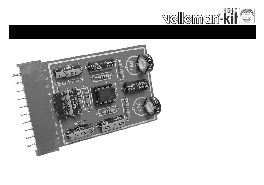
UNIVERSAL STEREO PRE - AMPLIFIER
K2572
r
e
i
f
i
l
p
m
a
e
r
p
e
s
L
b
o
t
ILLUSTRATED ASSEMBLY MANUAL H2572IP-1
s
t
s
o
o
m
i
s
l
l
a
i
o
n
w
o
.
s
l
a
n
g
Page 2
Features & Specifications
Specifications:
Power supply: 10 - 30V DC maximum, stabilized.
Current abs orption with out charge : typ. 5mA.
Adjustable gain : 40dB max.
Frequenc y range : 40H z - 30KHz (-3dB).
Output impedance : 1KΩ.
Max. Input voltage : 50mVrms (500mVrms)
Dimensions : 44 x 65mm / 1,7” x 2,6”.
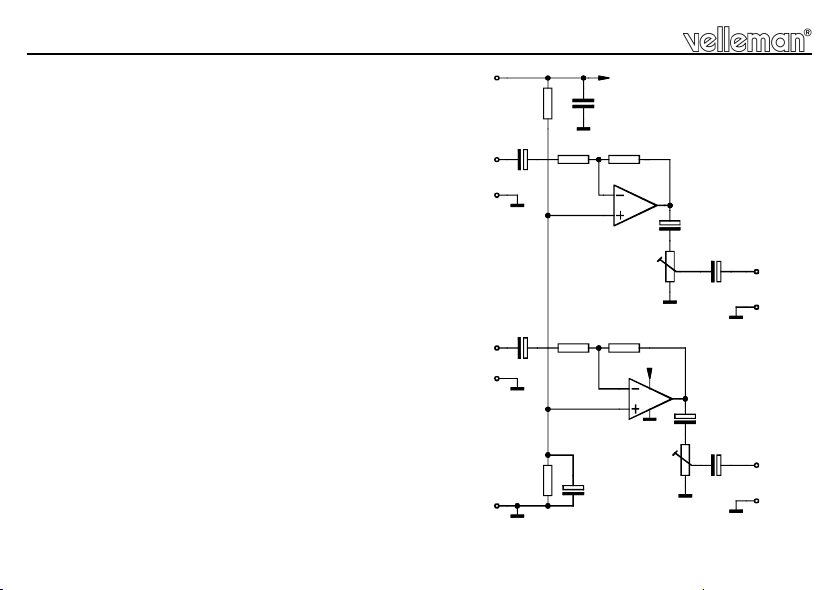
2
IN-L
IN-R
6
R2
C7
4
3
C6
7
8
R1
5
R6
R5
C4
2
3
A1,A2 = IC1
C1
+V
R3
1
A1
C2
C7
2
C3
RV2
OUT-L
1
C5
9
OUT-R
10
RV1
R4
+V
6
8
7
A2
5
4
Page 3
Assembly hints
0
.
0
0
0
1. Assembly (Skipping this can lead to troubles ! )
Ok, so we have your attention. These hints will help you to make this project successful. Read them carefully.
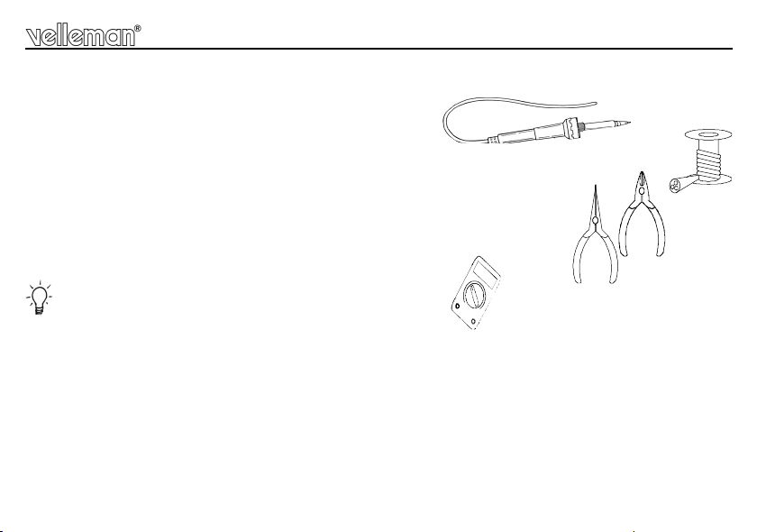
1.1 Make sure you have the right tools:
• A good quality soldering iron (25-40W) with a small tip.
• Wipe it often on a wet sponge or cloth, to keep it clean; then apply solder to the tip, to give it a wet look. This is called ‘thinning’ and will
protect the tip, and enables you to make good connections. When solder rolls off the tip, it needs cleaning.
• Thin raisin-core solder. Do not use any flux or grease.
• A diagonal cutter to t rim excess wires. To avoid injury when cutting excess l eads, ho ld the le ad so they
cannot fly towards the eyes.
• Needle nose pliers, for bending leads, or to hold components in place.
• Small blade and Phillips screwdrivers. A basic range is fine.
For some projects, a basic multi-meter is required, or might be handy
1.2 Assembly Hints :
⇒ Make sure the skill level matches your experience, to avoid disappointments.
⇒ Follow the instructions carefully. Read and understand the entire step before you perform each operation.
⇒ Perform the assembly in the correct order as stated in this manual
⇒ Position all parts on the PCB (Printed Circuit Board) as shown on the drawings.
⇒ Values on the circuit diagram are subject to changes.
⇒ Values in this assembly guide are correct*
⇒ Use the check-boxes to mark your progress.
⇒ Please read the included information on safety and customer service
* Typograp hical inac curacies excl uded. Al ways look for possi ble last minute manual updates, in dicated as ‘NOTE’ o n a separat e leafl et.
3
Page 4

Assembly hints
1.3 Soldering Hints :
1- Mount the component against the PCB surface and carefully solder the leads
2- Make sure the solder joints are cone-shaped and shiny
3- Trim excess leads as close as possible to the solder joint
REMOVE THEM FROM THE TAPE ONE AT A TIME !
AXIAL COMPONENTS ARE TAPED IN THE COR-
RECT MOUNTING SEQUENCE !
4
Page 5

Construction
C...
1. Resistors
R1 : 22K (2 - 2 - 3 - B)
R2 : 22K (2 - 2 - 3 - B)
R3 : 1MΩ (1 - 0 - 5 - B)
R4 : 1MΩ (1 - 0 - 5 - B)
R5 : 10K (1 - 0 - 3 - B)
R6 : 10K (1 - 0 - 3 - B)
R...
2. IC socket. Watch the
position of the notch!
IC1 : 8p
3. Ceramic Capacitor
C4 : 100nF (104, u1)
4. Electrolytic capacitors.
Watch the polarity !
C1 : 10µF
C2 : 1µF
C3 : 1µF
C5 : 1µF
C6 : 1µF
C7 : 1µF
C8 : 1µF
5. Potentiometers
RV1 : 1K
RV...
RV2 : 1K
C...
6 . IC. Watch the position of
the notch!
IC1 : TL072
5
Page 6

Use
7. Use
Ten connections are provided on the pcb to connect the print with a device. These connections are identical
to those of the RIAA preamplifier K2573 and in case you us e the connectors included in this kit, you may
interchange the two prints.
The grounds near the Ins and Outs ar e used to connect the shielded wires (-) of the connecting leads. The
output amplitude of the right and the left channel are totally independent s ettable by respectively RV1 &
RV2. As current consumption is very low, voltage can be taken from any well stabilized pow er supply of 10
trough 30V DC. Lower the gain from 100 to 10 if the input signal is bigger than 50mV (500mV max), by
replacing R5 & R6 by 100K resistors.
1. Ground
2. Out left
3. Ground
4. In left
5. Ground (Power supply)
6. + (power supply)
7. In right
8. Ground
9. Out right
10.Ground
Remarks : A nonwell stabilized power s upply will give a noise and hum. The leads, from and to the print,
must be as short as possible and make use of shielded wires only. Never place the preamp in the vicinity
of transformers or net.
6
Page 7

8. PCB
PCB
7
Page 8

VELLEMAN Components NV
www.velleman-kit.com
Modific ations and typographical err ors reserved
© Velleman Components nv.
H2572IP - 2003 - ED1 (rev 2.0)
Legen Heirweg 33
9890 Gavere
Belgium Europe
www.velleman.be
5 410329 310127
 Loading...