

Page 1

Total solder points: 18
Difficulty level: beginner 1 2 3 4 5 advanced
UNIVERSAL POWER SUPPLY 5 - 14DC / 1A
K2570
r
ou
y
er
pow
o
t
ay
w
y
as
e
e
h
T
ILLUSTRATED ASSEMBLY MANUAL H2570IP-1
pr
o
j
ec
.
s
t
Page 2

Features & Specifications
Features
Suits all Velleman kits requiring a regulated power supply between 5 and 12VDC, and no more than 1A.
Specifications :
Input voltage: 7-16VDC / 1A
Output voltage: 5-14VDC, regulated
Output current: max. 1A
Power limitation and thermal overload protection
Max. dissipation: 7W
PCB dimensions: 77 x 61mm (3.0" x 2.4")
Can be combined with :
K1771
K1803
K2032
K2572
K2573
K2579
K2651
K2655
FM - oscillator
Universal mono pre - amplifier
Digital panel meter
Universal stereo pre-amplifier
Stereo RIAA pre - amplifier
Universal start / stop timer
LCD panel meter
Electronic watchdog
K2656
K3400
K4601
K4900
K6400
K8015
VM114
Universal chrystal timebase
Dual electronic dice
Audio / video tv modulator
Telephone amplifier
Code lock
Multifunction relay switch
7W mono audio amplifier
2
Page 3
Assembly hints
0
.
0
0
0
1. Assembly (Skipping this can lead to troubles ! )
Ok, so we have your attention. These hints will help you to make this project successful. Read them carefully.
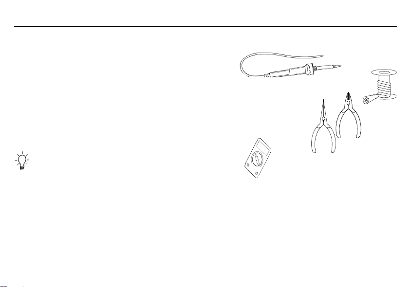
1.1 Make sure you have the right tools:
• A good quality soldering iron (25-40W) with a small tip.
• Wipe it often on a wet sponge or cloth, to keep it clean; then apply solder to the tip, to give it a wet look. This is called ‘thinning’ and will
protect the tip, and enables you to make good connections. When solder rolls off the tip, it needs cleaning.
• Thin raisin-core solder. Do not use any flux or grease.
• A diagonal cutter to trim excess wires. To avoid injury when cutting excess leads, hold the lead so they
cannot fly towards the eyes.
• Needle nose pliers, for bending leads, or to hold components in place.
• Small blade and Phillips screwdrivers. A basic range is fine.
For some projects, a basic multi-meter is required, or might be handy
1.2 Assembly Hints :
⇒ Make sure the skill level matches your experience, to avoid disappointments.
⇒ Follow the instructions carefully. Read and understand the entire step before you perform each operation.
⇒ Perform the assembly in the correct order as stated in this manual
⇒ Position all parts on the PCB (Printed Circuit Board) as shown on the drawings.
⇒ Values on the circuit diagram are subject to changes.
⇒ Values in this assembly guide are correct*
⇒ Use the check-boxes to mark your progress.
⇒ Please read the included information on safety and customer service
* Typographical inaccuracies excluded. Always look for possible last minute manual updates, indicated as ‘NOTE’ on a separate leaflet.
3
Page 4

Assembly hints
1.3 Soldering Hints :
1- Mount the component against the PCB surface and carefully solder the leads
2- Make sure the solder joints are cone-shaped and shiny
3- Trim excess leads as close as possible to the solder joint
REMOVE THEM FROM THE TAPE ONE AT A TIME !
DO NOT BLINDLY FOLLOW THE ORDER OF THE
COMPONENTS ONTO THE TAPE. ALWAYS CHECK
THEIR VALUE ON THE PARTS LIST!
4
Page 5
Construction
C...
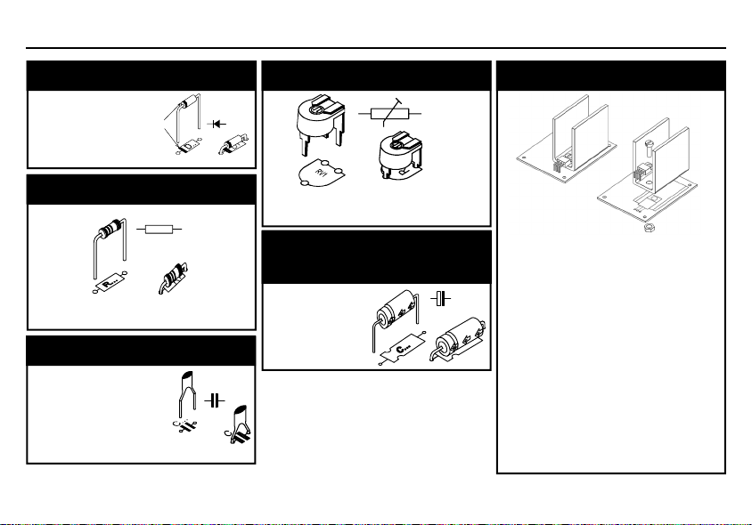
1. Diodes. Watch the polarity !
D1 : 1N4007
D2 : 1N4007
D3 : 1N4007
D4 : 1N4007
CATHODE
D.. .
2. Resistor
R1 : 270 (2 - 7 - 1 - B)
3. Capacitors
C1 : 100nF (104)
C3 : 100nF (104)
R...
4. Trim potentiometer
RV1 : 470 ohm
RV1
5. Electrolytic Capacitor.
Watch the polarity !
C2 : 2200µF
C...
6. Voltage regulator
VR : UA7805
Place the heatsink and the
regulator on the PCB.
Ensure that the hole of the
heatsink and the one of the
regulator correspond to the hole
in the PCB.
Use heatsink compound to en-
sure good heat dissipation.
Fix the two components with an
M3 bolt and nut.
Now, the regulator may be sol-
dered.
5
Page 6

Use & PCB
7. Use
To use the circuit without problem, take into account
the power dissipation in the regulator.
The transformer voltage must always be 2V higher
than the maximum desired output voltage.
If, for instance, you need an output voltage of 12V,
then you need to fit a transformer of 14V.
If, as an output voltage you only need 6V, use a transformer having 8V and not 14V, because with an 8V
transformer the dissipation in the regulator will be of
approximately 5W when drawing a current of 1A. With
a 14V transformer, the dissipation will be higher than
10W. In the second case the regulator will die in a few
minutes.
The transformer should be connected to the points “AC
IN” and the output voltage is connected at points + and
- (Vreg).
6
8. PCB
Page 7

9. DIAGRAM
Diagram
7
Page 8

Modifications and typographical errors reserved
© Velleman nv.
H2570IP - 2004 - ED1 (rev.1.0)
Legen Heirweg 33, 9890 Gavere
VELLEMAN NV
Belgium - Europe
5 410329 330781
 Loading...