

Page 1

PROMIX66/88
6-CHANNEL/8-CHANNEL PROFESSIONAL MIXER
PROFESSIONEEL 6-KANAALS / 8-KANAALS MENGPANEEL
TABLE DE MIXAGE À 6/8 CANAUX
MESA DE MEZCLAS PROFESIONAL DE 6/8 CANALES
PROFESSIONELLES 6-KANAL- / 8-KANAL-MISCHPULT
PROFESJONALNY MIKSER 6-cio/8-mio KANAŁOWY
USER MANUAL
GEBRUIKERSHANDLEIDING
NOTICE D’EMPLOI
MANUAL DEL USUARIO
BEDIENUNGSANLEITUNG
INSTRUKCJA OBSŁUGI
Page 2

PROMIX66/88 2 VELLEMAN
PROMIX66/88 – 6-CHANNEL/8-CHANNEL PROFESSIONAL MIXER
1. Introduction & Features
To all residents of the European Union
Important environmental information about this product
This symbol on the device or the package indicates that disposal of the device after its lifecycle could harm
the environment.
Do not dispose of the unit (or batteries) as unsorted municipal waste; it should be taken to a specialised
company for recycling.
This device should be returned to your distributor or to a local recycling service.
Respect the local environmental rules.
If in doubt, contact your local waste disposal authorities.
Thank you for buying the PROMIX66/88! Please read the manual thoroughly before bringing this device into service.
If the device was damaged in transit, don't install or use it and contact your dealer.
2. Safety Instructions
• Damage caused by disregard of certain guidelines in this manual is not covered by the warranty and the dealer
will not accept responsibility for any ensuing defects or problems.
• A qualified technician should install and service this device.
• Do not switch the device on immediately after it has been exposed to changes in temperature. Protect the device
against damage by leaving it switched off until it has reached room temperature.
• Do not expose the device to liquids and make sure not to place any object containing liquid on top of the device.
• Note that damage caused by user modifications to the device is not covered by the warranty.
• Keep the device away from children and unauthorised users.
3. Description
MONO Input Channel (fig. 1)
1. MIC Input
Each mono input channel offers a balanced microphone input via the XLR connector and also features a
switchable +48V phantom power supply for condenser microphones. The XLR jack is configured for pin 1
(ground), pin 2 (positive (+)) and pin 3 (negative (-)).
2. LINE IN
The LINE input is designed to accept balanced or unbalanced line level signals such as those from keyboards,
drum machines or samplers. There is enough gain available on the line input to accept even lower level signals
such as those from an unbalanced microphone or guitar output. If a balanced signal is to be connected to the line
input, then a 1/4" TRS (stereo) phone plug should be wired for the tip (positive (+)), the ring (negative (-)) and the
sleeve (ground).
NOTE: Either the MIC or the LINE input of a given channel can be connected at one time. Never connect both
simultaneously to the same channel.
Be very careful during the installation: touching live wires can cause life-threatening electroshocks.
Keep this device away from rain and moisture.
Unplug the mains lead before opening the housing.
Page 3

PROMIX66/88 3 VELLEMAN
3. TRIM Control
The TRIM control adjusts the input sensitivity (channel gain) of the MIC and LINE inputs on
the mono input channels. This control can be adjusted to accommodate input signals from a
wide variety of sources, from the high outputs from keyboards or drum machines to the small
signal outputs of microphones. This wide range eliminates the need for MIC / LINE switching.
The best S/N balance and dynamic range will be achieved if you adjust the TRIM control on
each channel separately so that the PEAK LED (7) for that channel lights occasionally.
NOTE: This control should always be turned fully anticlockwise whenever you connect or
disconnect a signal source to one of the inputs.
4. EQUALIZER Controls
All mono input channels are fitted with three-band EQ. The upper (HIGH) and lower (LOW)
shelving controls have their frequencies fixed at 12kHz and 80Hz respectively. The midrange
control has a peaking response, with Q fixed at 2 octaves and the frequency at 2.5KHz. All
three bands have up to 15dB of cut and boost with a centre detent for "off".
5. AUX / EFF SEND Control
The AUX / EFF controls are mono and post-EQ and post-fader. The signal level sent to the
AUX / EFF bus will be affected by the channel fader setting. The AUX configuration is ideal for
almost all monitoring purpose e.g. for a separate stage monitor mix in live performances or a
studio room monitor in recording applications, such as for a headphone cue system. The EFF
controls the adjustment of level sent by each channel to the internal DSP (Digital Sound
Processor).
6. PAN Control
The channel PAN positions the output of the channel in the stereo field of the Master Mix. Its
constant-power design ensures there are no level discrepancies whether a signal is hardpanned, centre-stage or somewhere in-between.
7. PEAK Indicator
The PEAK LED illuminates when a channel is going into overload. It detects the peak level
after the EQ and will light at 3dB before clipping to warn that the signal is approaching
overload. You do not want the PEAK LED to light except very intermittently during a take or a
mix. If it does light persistently, reduce input gain with the TRIM control (3).
8. CHANNEL GAIN Control
The channel GAIN controls determine the output signal level to the master mix bus. There is
no PFL function on the mixer. In order to audition any single channel for proper gain, you can
turn off the gain control of all the other channels (fully anticlockwise) and set both the
auditioned channel and MASTER MIX control (29) to unity gain (0dB). The LED OUTPUT
meter (21) should read around 0dB.
STEREO Input Channel (fig. 2)
4. EQUALIZER Controls
The stereo channel EQs operate in the same manner as those in the mono channels. The left
and right signals will be affected equally. A stereo equalizer is generally preferable to using
two mono equalizers when equalizing a stereo signal as it avoids possible discrepancies
between the left and right settings.
5. AUX / EFF SEND Control
These are the same as for the mono channels. Note that a mono sum is taken from the stereo
input.
8. CHANNEL GAIN CONTROL
The channel GAIN controls determine the output signal level to the MASTER MIX bus. There
is no PFL function on the mixer. In order to audition any single channel for proper gain you
can turn off the gain control of all the other channels (fully anticlockwise) and set both the
auditioned channel and MASTER MIX control (29) to unity gain (0dB). The LED OUTPUT
meter (21) should read around 0dB.
Page 4

PROMIX66/88 4 VELLEMAN
9. LINE IN
Each stereo channel has two balanced line level inputs on 1/4” TRS jacks for left and right channels (tip = positive
(+), ring = negative (-), sleeve = ground). If only the connector marked “L” (left) is used, the channel operates in
mono. The stereo channels are designed to handle typical line level signals. The input signals to these jacks can
be either balanced or unbalanced.
10. BAL Control
For a mono input to the L (MONO) input the function of the control is the same as the PAN controls (6) of the
mono channels. However, when a channel is run in stereo, this control functions as a BALANCE control,
determining the relative balance of the left and right channel signals being sent to the left and right MASTER MIX
buses. For example, with the BALANCE control turned fully clockwise, only the right portion of the channel’s
stereo signal will be routed to the MASTER MIX.
MASTER Section (fig. 3 & 4)
11. STEREO AUX RETURNS (LEFT / MONO, RIGHT)
The AUX RETURN jacks are the mono or stereo returns for AUX SEND. If you connect a signal to the LEFT /
MONO RETURN jack only, the AUX RETURN will operate in mono and the signal will be routed to the AUX
RETURN control (19) and then mixed into the left and right MASTER MIX stereo outputs (13). The separate left
and right return jacks are provided for use with stereo signals such as those from the output of a stereo effects
processor. The left and right return signals will be routed to the AUX RETURN level control (19) and mixed into
the left and right STEREO OUT (13) while maintaining stereo separation.
12. AUX SEND
The AUX SEND is the output for the signal sent from the channel AUX / EFF controls (5) and by the AUX SEND
controls (18) control. They are 1/4” unbalanced phone jacks (tip = positive (+), sleeve = ground). AUX SEND is a
post-fader. These signals can be sent to the input of an effects processor, multi-track recorder, or used for any
other line-level auxiliary purpose.
13. STEREO Outputs
Use these jacks to connect to an external power amplifier if extra output power for a larger PA system is required.
The stereo outputs are left (L) and right (R) unbalanced 1/4” phone jacks, wired as tip = positive (+), sleeve =
ground.
14. TAPE Inputs
These jacks will accept the signal from an external device with a stereo output such as a cassette recorder.
15. REC Outputs
The REC outputs also provide an output of the MASTER MIX. These outputs are RCA jacks and designed
primarily for inputs to tape recorders etc.
Page 5

PROMIX66/88 5 VELLEMAN
16. L-R Control Room Outputs
The L-R control room outputs can be connected to an amp to power stereo control room (or other) monitor
speakers and are 1/4” unbalanced phone jacks, wired as tip = positive (+), sleeve = ground.
17. PHONES Output
The PHONES output will feed headphones and is a 1/4” TRS jack, wired as tip = left signal, ring = right signal,
sleeve = ground.
18. AUX SEND
This is a master control that adjusts the output signal level at the AUX SEND (12) jack.
19. AUX RETURN Control
The left and right return signals will be routed to the AUX RETURN level control and mixed into the left and right
stereo OUT (13) while maintaining stereo separation.
20. PHONES/CONTROL ROOM CONTROL
The mixer allows you to monitor the MASTER
MIX. The signal level is adjusted with the
PHONES / CONTROL ROOM control and
routed to both the CONTROL ROOM (16)
and HEADPHONES (17) outputs.
21. LED OUTPUT Meter
The 10-stage LED OUTPUT meter displays
the MASTER MIX output level.
22. PHANTOM POWER ON/OFF Switch
When using condenser microphones,
+48VDC can be switched globally on or off to
the XLR MIC inputs for all mono channels.
When this switch is in the “ON” position, the
PHANTOM POWER ON LED (25) will light
and +48VDC will be provided between pins 2
and 3 on all the mono MIC input XLR
connectors. If you do not need phantom
power, be sure to turn this switch to the “OFF”
position.
NOTE: It is safe to connect balanced dynamic
microphones or line-level devices
even if this switch is on, but
connecting unbalanced devices or
devices whose transformers are
centre-grounded will cause hum or
malfunctions. Shorting the +48VDC can also damage your mixer. Also, mute the monitor or PA speakers
first when turning the phantom power on or off.
23. TAPE / REC TO CONTROL ROOM Switch
Use the TAPE / REC TO CONTOL ROOM switch to route signals from the TAPE input (14) to the PHONES /
CONTROL ROOM control (20).
24. TAPE / REC TO MASTER Switch
Use the TAPE / ECHO TO MASTER switch to route signals from the TAPE input (14) to the MASTER MIX GAIN
control (29).
25. PHANTOM POWER LED
The red +48V LED lights up when the phantom power is turned on.
26. POWER ON LED
The red LED indicates that the console is powered on.
Page 6

PROMIX66/88 6 VELLEMAN
DIGITAL EFFECTS Section
27. EFFECTS Display
Press either ECHO effect buttons to scroll in either direction through the 16 presets. The numeric effects display
will indicate which of the 16 effect presets has been selected.
28. ECHO EFFECT SELECT Buttons
The built-in DSP (Digital Sound Processor) offers 16 different preset level and echo intervals selectable by the
echo effect UP / DOWN buttons. The DSP processes the signal on the EFFECTS bus, which is the sum of the
mono and stereo channel inputs controlled by the EFF control (5).
29. MASTER MIX GAIN Control
The output level routed to the stereo outputs and REC outputs is determined ultimately by the setting of the
MASTER MIX GAIN control.
30. EFFECT SEND
The EFFECT SEND control adjusts the level of the signal on the EFFECTS bus fed to the DSP.
31. EFFECT (ECHO) RETURN
The EFFECT (ECHO) RETURN control adjusts the number of repeats of the echo effect selected with the UP /
DOWN buttons (28).
32. EFFECT GAIN
The EFFECTS GAIN fader controls the signal level sent to the MASTER MIX buses.
Rear Panel (fig. 5)
33. AC POWER IN Socket
Connect the enclosed power supply to the 3-pin mains connector on the rear of the console. Use the included
adapter to connect the console to the mains.
34. MAIN POWER Switch
This switches the mixer ON or OFF.
NOTE: Be sure to switch on the power to your mixer before switching on the amplification system.
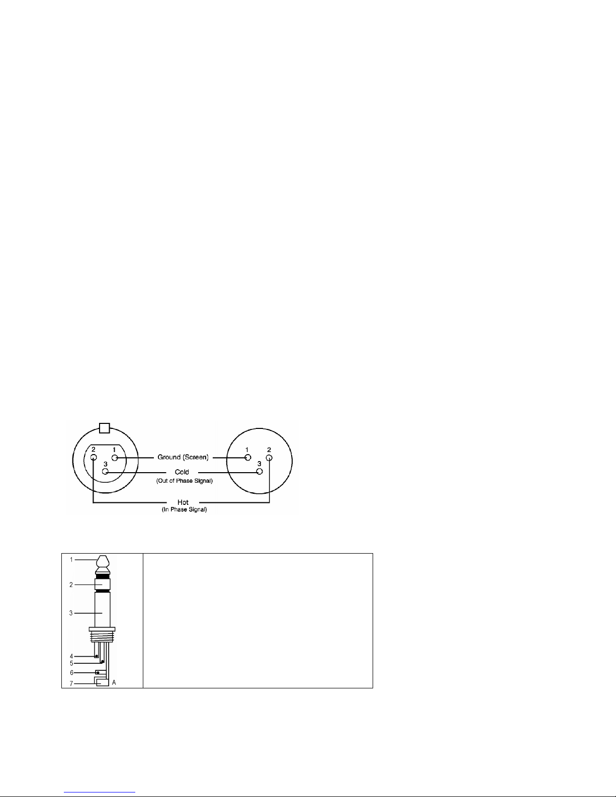
4. Connections
Unbalanced equipment may be connected to balanced inputs/outputs. Either use mono 1/4” jacks or connect the ring
and sleeve of TRS jacks. Never use unbalanced XLR connectors on the MIC input connectors when using the
phantom power supply.
Microphone input Group & mix outputs
Socket (female) Plug (male)
Page 7

PROMIX66/88 7 VELLEMAN
Headphones
1. Tip = left signal
2. Ring = right signal
3. Sleeve = ground
4. Tip
5. Ring
6. Sleeve
7. Strain relief clamp
Unbalanced use of mono 1/4” plugs
1. Tip = signal
2. Sleeve = ground
3. Tip
4. Sleeve
5. Strain relief clamp
Balanced use of stereo 1/4” plugs
1. Tip = hot (+)
2. Ring = cold (-)
3. Sleeve = ground
4. Tip
5. Ring
6. Sleeve
7. Strain relief clamp
5. Technical Specifications
Input
Input Connector Input Impedance Nominal Level Max. Level
MONO CH MIC XLR > 1.3K ohms +2dBm +14dBm
MONO CH LINE ¼” TRS > 10K ohms +4dBm +22dBm
STEREO CH LINE ¼” TRS > 10K ohms +4dBm +22dBm
TAPE IN RCA PIN JACKS > 10K ohms +2dBm +22dBm
AUX RETURNS ¼” TRS > 10K ohms +4dBm +22dBm
Output
Output Connector Input Impedance Nominal Level Max. Level
STEREO OUT L/R ¼” TRS 120 ohms +4~6dBm +22dBm
AUX SEND ¼” TRS 120 ohms +4~6dBm +20dBm
CTRL R OUT ¼” TRS 120 ohms +4~6dBm +22dBm
REC OUT RCA PIN JACKS 1K ohms +4~6dBm +22dBm
PHONES ¼” TRS 100 ohms - 40mW * 2
Page 8

PROMIX66/88 8 VELLEMAN
Frequency Response 20Hz to 20KHz
THD 0.02%, 20Hz~20KHz @ 1KHz, 0dBm
Input Channel Equalization
High 12KHz, +/- 15dB, Q fixed at 2 octaves
Mid 2.5KHz, +/- 15dB, Q fixed at 1 octave
Low 80Hz, +/- 15dB, Q fixed at 2 octaves
Gain Control Range
Input Channel Trim Control stop to stop, MIC +10dB~+60dB
LINE +10dB~+40dB
Channel/Master/Effect Faders -∞ to +15dB
Aux Send/Aux Master Send OFF to +15dB
Aux Return OFF to +20dB
Channel and Master Effects Send OFF to +15dB
Crosstalk @ 1KHz -78dB~-68dB
Hum and Noise 20Hz-20KHz, Rs = 150 ohms, input TRIM @ 0dB, sensitivity at -60dB
Equivalent Input Noise -129dBm
Residual Output Noise <90dBm
VU Meters 10-segment LED x 2
Phantom Power +48VDC
Power Supply 120VAC / 60Hz or 230VAC / 50Hz selectable
Consumption 25W
Dimensions
PROMIX66 253 x 236 x 55mm
PROMIX88 253 x 290 x 55mm
Weight
PROMIX66 1.72kg
PROMIX88 2kg
The information in this manual is subject to change without prior notice.
PROMIX66/88 – PROFESSIONEEL 6-KANAALS / 8-KANAALS MENGPANEEL
1. Inleiding en kenmerken
Aan alle ingezetenen van de Europese Unie
Belangrijke milieu-informatie betreffende dit product
Dit symbool op het toestel of de verpakking geeft aan dat, als het na zijn levenscyclus wordt weggeworpen,
dit toestel schade kan toebrengen aan het milieu.
Gooi dit toestel (en eventuele batterijen) niet bij het gewone huishoudelijke afval; het moet bij een
gespecialiseerd bedrijf terechtkomen voor recyclage.
U moet dit toestel naar uw verdeler of naar een lokaal recyclagepunt brengen.
Respecteer de plaatselijke milieuwetgeving.
Hebt u vragen, contacteer dan de plaatselijke autoriteiten inzake verwijdering.
Dank u voor uw aankoop! Lees deze handleiding grondig voor u het toestel in gebruik neemt. Werd het toestel
beschadigd tijdens het transport, installeer het dan niet en raadpleeg uw dealer.
Page 9

PROMIX66/88 9 VELLEMAN
2. Veiligheidsinstructies
• De garantie geldt niet voor schade door het negeren van bepaalde richtlijnen in deze handleiding en uw dealer zal
de verantwoordelijkheid afwijzen voor defecten of problemen die hier rechtstreeks verband mee houden.
• Laat dit toestel installeren en onderhouden door een geschoolde technicus.
• Om beschadiging te vermijden, zet u het toestel best niet aan onmiddellijk nadat het werd blootgesteld aan
temperatuurschommelingen. Wacht tot het toestel op kamertemperatuur gekomen is.
• Houd het toestel uit de buurt van vloeistoffen en plaats geen drank op het mengpaneel.
• Schade door wijzigingen die de gebruiker heeft aangebracht aan het toestel vallen niet onder de garantie.
• Houd dit toestel uit de buurt van kinderen en onbevoegden.
3. Omschrijving
MONO ingangskanaal (zie fig. 1)
1. MIC-ingang
Elk mono ingangskanaal bestaat uit een gebalanceerde microfooningang via de XLR-aansluiting en beschikt over
een schakelende fantoomvoeding (+48V) voor condensatormicrofoons. De XLR jack-aansluiting is geconfigureerd
voor pin 1 (aarding), pin 2 (positief (+)) en pin 3 (negatief (-)).
2. LINE IN
De LINE-ingang is ontworpen om gebalanceerde en niet-gebalanceerde line-signalen te ontvangen zoals die van
een keyboard, drumcomputer of sampler. Er is voldoende versterking aanwezig op de line-ingang om zelfs
zwakkere signalen zoals die van een ongebalanceerde microfoon of een gitaarsignaal te ontvangen. Wenst u een
gebalanceerd signaal aan de line-ingang te sluiten, bedraad een 1/4” TRS (stereo) plug als volgt: tip (positief (+)),
de ring (negatief (-)) en de huls (aarding).
OPMERKING: U kunt of de MIC-ingang of de LINE-ingang aansluiten. Sluit nooit beide tegelijkertijd op eenzelfde
kanaal.
3. TRIM-regeling
Met de TRIM-regeling regelt u de ingangsgevoeligheid (kanaalversterking) van de MIC-ingang en de LINE-ingang
van de mono ingangskanalen. Regel deze knop zodat u het ingangssignaal van verscheidene bronnen kunt
ontvangen, van de sterke uitgangssignalen ven een keyboard of drumcomputer tot de zwakke signalen van een
microfoon. Het grote bereik maakt MIC / LINE-schakeling overbodig. De beste S/R-verhouding en dynamisch
bereik verkrijgt u wanneer u de TRIM-regeling op elk kanaal afzonderlijk regelt zodanig dat de PEAK LED (7)
maar af en toe oplicht.
OPMERKING: Draai deze regelknop volledig naar links voordat u een signaal aansluit of ontkoppelt.
4. EQUALIZER
Alle mono ingangskanalen beschikken over een driebands equalizer. De bovenste (HIGH) en onderste (LOW)
potmeters hebben een frequentie van 12kHz respectievelijk 80Hz. De regelknop voor de middentonen heeft een
piekrespons met een Q van 2 octaven en een frequentie van 2.5KHz. Alle drie banden hebben tot 15dB
versterking of verzwakking met een centernok voor "off".
5. AUX / EFF SEND
De AUX / EFF-regelknoppen zijn mono, post-EQ en post-fader. Het signaalniveau dat naar de AUX / EFF-bus
wordt gezonden, zal beïnvloed worden door de instelling van de fader. De AUX-configuratie is ideaal voor bijna
elke monitoring, bvb. een afzonderlijke geluidsregeling van de podiummonitor tijdens een live-optreden of een
Wees voorzichtig bij de installatie: raak geen kabels aan die onder stroom staan om dodelijke elektroshocks
te vermijden.
Bescherm dit toestel tegen regen en vochtigheid.
Verzeker u ervan dat het toestel niet aangesloten is op een stroombron alvorens het te openen.
Page 10

PROMIX66/88 10 VELLEMAN
geluidsregeling in een studio tijdens een opname zoals voor een hoofdtelefoon. De EFF regelt het niveau dat elke
kanaal naar de interne DSP (Digital Sound Processor) zendt.
6. PAN-regeling
De PAN-regeling plaatst de uitgang van een kanaal in het stereobeeld van de mix. Het toestel zorgt ervoor dat er
zich geen discrepanties in het niveau voorkomen, of een signaal nu langs een kant, centraal of ergens tussenin
staat.
7. PEAK-aanduiding
De PEAK-aanduiding licht op wanneer een kanaal overstuurt. Het toestel neemt een piek waar na de EQ, licht op
3dB voor de vervorming en waarschuwt u wanneer het signaal wordt overstuurd. Zorg dat de PEAK-aanduiding
niet oplicht uitgenomen af en toe tijdens een mix. Licht de aanduiding op een constante basis, verminder de
ingangsversterking door middel van de TRIM-regeling (3).
8. CHANNEL GAIN-regeling
De GAIN-regeling bepaalt het niveau van het uitgangssignaal naar de master mix bus. De mengtafel is niet
voorzien van een PFL-functie. Om elk apart kanaal op versterking te testen, draai de gain-knop van alle andere
kanalen toe (naar links) en stel de regelknop van zowel het gewenste kanaal als die van de MASTER MIX (29) op
nulversterking (0dB). De LED-meter (21) zou 0dB moeten aanwijzen.
STEREO ingangskanaal (fig. 2)
4. EQUALIZER
De equalizer van de stereo kanalen werken zoals de equalizer van de mono kanalen. De linkse en de rechtse
signalen worden op dezelfde manier beïnvloed. Gebruik eerder een stereo equalizer dan twee mono equalizers
wanneer u een stereo signaal wenst te mixen. Zo vermijdt u mogelijke discrepanties tussen de linkse en de
rechtse instellingen.
5. AUX / EFF SEND
Identiek als de mono kanalen. Een mono som wordt van de stereo ingang genomen.
8. CHANNEL GAIN-regeling
De GAIN-regeling bepaalt het niveau van het uitgangssignaal naar de master mix bus. De mengtafel is niet
voorzien van een PFL-functie. Om elk apart kanaal op versterking te testen, draai de gain-knop van alle andere
kanalen toe (naar links) en stel de regelknop van zowel het gewenste kanaal als die van de MASTER MIX (29) op
nulversterking (0dB). De LED-meter (21) zou 0dB moeten aanwijzen.
9. LINE IN
Elk stereokanaal beschikt over twee gebalanceerde LINE-ingangen langs 1/4” TRS jack-aansluitingen voor het
linkse en het rechtse kanaal (tip = positief (+), ring = negatief (-), huls = aarding). Gebruikt u enkel de aansluiting
“L” (links), dan werkt het kanaal in mono. De stereokanalen zijn ontworpen om typische signalen aan te pakken.
De ingangssignalen naar deze jack-aansluitingen kunnen gebalanceerd of niet-gebalanceerd zijn.
10. BAL-regeling
Deze regeling werkt op dezelfde manier als de PAN-regeling (6) voor een mono-ingang naar de L (MONO)
ingang. Wanneer een kanaal echter in stereo functioneert, dan werkt deze knop als een balansregeling tussen
het linker- en rechterkanaal. Voorbeeld: Draai de BAL-regeling volledig naar rechts om enkel het rechtse gedeelte
van een stereosignaal hoorbaar te maken.
MASTER-gedeelte (zie fig. 3 & 4)
11. STEREO AUX RETURNS (LEFT / MONO, RIGHT)
De AUX RETURN-aansluitingen zijn de mono of stereo retours voor de AUX SEND. Wanneer u een signaal enkel
koppelt aan de LEFT / MONO RETURN-aansluiting, dan zal de AUX RETURN in mono functioneren en het
signaal naar de AUX RETURN-regeling (19) gestuurd worden waarna het wordt gemixt in de links en rechtse
MASTER MIX stereo-uitgangen (13). De afzonderlijke linkse en rechtse retouraansluitingen zijn meegeleverd
zodat u stereosignalen zoals deze van een stereo effectprocessor kunt gebruiken. De linkse en rechtse signalen
worden naar de AUX RETURN-regeling (19) gestuurd en gemixt in de linkse en rechtse STEREO OUT (13) terwijl
er nog steeds stereoscheiding aanwezig is.
12. AUX SEND
De AUX SEND is een uitgang voor het signaal afkomstig van de AUX / EFF-regeling (5) en gezonden door de
AUX SEND-regeling (18). Deze zijn niet-gebalanceerde 1/4” phone-pluggen (tip = positief (+), huls = aarding).
Page 11

PROMIX66/88 11 VELLEMAN
AUX SEND is een post fader. Deze signalen kunnen worden gezonden naar de ingang van een effectprocessor,
multi-track recorder of gebruikt worden met een aangesloten line-level toestel.
13. STEREO-uitgangen
Gebruik deze jackaansluitingen om de externe versterker aan te sluiten wanneer u extra vermogen nodig hebt
voor een groter PA-systeem. De stereo uitgangen zijn links (L) en rechts (R) niet-gebalanceerde 1/4” Phonepluggen, met tip = positief (+), huls = aarding.
14. TAPE-ingangen
Deze jacks ontvangen het signaal van een externe toestel met stereo uitgang zoals een cassetterecorder.
15. REC-uitgangen
De REC-uitgangen leveren een uitgang voor de MASTER MIX. Deze uitgangen zijn van het RCA-type en zijn
ontworpen als ingangen voor bandrecorders enz.
16. L-R Control Room
Deze uitgangen kunnen aan een versterker worden aangesloten om stereo monitors (of andere) te voeden. De
uitgangen zijn niet-gebalanceerde 1/4” phone-pluggen met tip = positief (+), huls = aarding.
17. PHONES
De PHONES-uitgang voedt de hoofdtelefoon en is een 1/4” TRS jack, met tip = links signaal, ring = rechts
signaal, huls = aarding.
18. AUX SEND
Dit is een master-regeling waarmee u het niveau van het uitgangssignaal kunt regelen aan de AUX SEND (12)
jack.
19. AUX RETURN
De linkse en rechtse retoursignalen worden naar de AUX RETURN gezonden en gemixt in een links en een
rechts STEREO OUT (13) terwijl er nog steeds stereoscheiding aanwezig is.
20. PHONES/CONTROL ROOM CONTROL
Met de mengtafel kunt u de MASTER MIX controleren. Het signaalniveau wordt met PHONES / CONTROL
ROOM geregeld en verzonden naar zowel de CONTROL ROOM (16) en de HEADPHONES (17).
21. LED OUTPUT
De 10-traps LED OUTPUT-meter geeft het uitgangsniveau van de MASTER MIX weer.
22. FANTOOMVOEDING ON/OFF
Gebruikt u condensatormicrofoons, dan kunt u +48VDC in- of uitschakelen. Wanneer de schakelaar op “ON”
staat, dan licht de LED van de FANTOOMVOEDING (25) op en pinnen 2 en 3 van alle mono XLR
microfooningangen worden voorzien van een spanning van +48VDC. Hebt u geen fantoomvoeding nodig, plaats
de schakelaar dan op “OFF”.
OPMERKING: U kunt gerust gebalanceerde dynamische microfoons of line level toestellen aansluiten, ook al
staat deze schakelaar op “ON”. Sluit u niet-gebalanceerde toestellen of toestellen met een
transformator met centrale aarding aan, dan kan dit brom of een slechte werking veroorzaken.
Een kortsluiting van de +48VDC kan eveneens uw mengtafel beschadigen. Demp eerst de
monitors of de PA-luidsprekers alvorens de fantoomvoeding van uw mengtafel aan of uit te
schakelen.
23. TAPE / REC TO CONTROL ROOM
Gebruik deze schakelaar om de signalen van de TAPE-uitgang (14) naar de PHONES / CONTROL ROOM (20)
te zenden.
24. TAPE / REC TO MASTER
Gebruik deze schakelaar om de signalen van de TAPE-ingang (14) naar de MASTER MIX GAIN (29) te zenden.
25. FANTOOM VOEDINGLED
De rode LED licht op wanneer de fantoomvoeding in- of uitgeschakeld wordt.
26. VOEDINGLED
De rode LED geeft weer of de tafel in- of uitgeschakeld is.
Page 12

PROMIX66/88 12 VELLEMAN
DIGITALE EFFECTEN
27. EFFECT-weergave
Druk op een ECHO effectknop om door de 16 voorkeuzeprogramma’s te rollen. De numerieke display geeft weer
welke van de 16 voorkeuzeprogramma’s is geselecteerd.
28. ECHO EFFECT keuzeknoppen
De ingebouwde DSP (Digital Sound Processor) biedt 16 verschillende echo-instellingen die met de UP / DOWNknoppen kunnen worden geselecteerd. De DSP verwerkt het signaal op de EFFECTS-bus, het geheel van de
mono en stereo-ingangen, die door EFF (5) kan bijgeregeld worden.
29. MASTER MIX GAIN
Het uitgangsniveau dat naar de stereo uitgangen en REC-uitgangen is verzonden, wordt uiteindelijk bepaald door
de regeling van MASTER MIX GAIN.
30. EFFECT SEND
Hiermee regelt u het signaalniveau op de EFFECT-bus naar de DSP.
31. EFFECT (ECHO) RETURN
De EFFECT (ECHO) RETURN regelt het aantal herhalingen van de echo die u met de UP / DOWN-knoppen (28)
heeft geselecteerd.
32. EFFECT GAIN
Met de EFFECTS GAIN fader regelt u het signaalniveau naar de MASTER MIX-bussen.
Achterpaneel (zie fig. 5)
33. AC-voedingsingang
Verbind de meegeleverde voeding met de 3-pin aansluiting achteraan het toestel. Gebruik enkel de
meegeleverde adapter.
34. VOEDINGSSCHAKELAAR
Schakel de mengtafel in- of uit.
OPMERKING: Schakel eerst uw mengtafel in alvorens de luidsprekers in te schakelen.
4. Aansluitingen
U mag niet-gebalanceerde toestellen met de gebalanceerde in- of uitgangen verbinden. Gebruik mono 1/4” jackaansluitingen of verbind de ring en de huls van de TRS jack-aansluitingen. Gebruik nooit niet-gebalanceerde XLRaansluitingen met de MIC-ingangen wanneer u de fantoomvoeding gebruikt.
Microfooningang Groep- & mixuitgangen
Doos (vrouwelijk) Plug (mannelijk)
Page 13

PROMIX66/88 13 VELLEMAN
Hoofdtelefoon
1. Tip = signaal links
2. Ring = signaal rechts
3. Huls = aarding
4. Tip
5. Ring
6. Huls
7. Snoerontlastingsklem
Niet-gebalanceerde mono 1/4” pluggen
1. Tip = signaal
2. Huls = aarding
3. Tip
4. Huls
5. Snoerontlastingsklem
Gebalanceerde stereo 1/4” pluggen
1. Tip = hot (+)
2. Ring = cold (-)
3. Huls = aarding
4. Tip
5. Ring
6. Huls
7. Snoerontlastingsklem
5. Technische specificaties
Ingang
Ingang Connector Ingangsimpedantie Nominaal niveau Max. niveau
MONO CH MIC XLR > 1.3K ohm +2dBm +14dBm
MONO CH LINE ¼” TRS > 10K ohm +4dBm +22dBm
STEREO CH LINE ¼” TRS > 10K ohm +4dBm +22dBm
TAPE IN RCA PIN JACKS > 10K ohm +2dBm +22dBm
AUX RETURNS ¼” TRS > 10K ohm +4dBm +22dBm
Uitgang
Uitgang Connector Ingangsimpedantie Nominaal niveau Max. niveau
STEREO OUT L/R ¼” TRS 120 ohm +4~6dBm +22dBm
AUX SEND ¼” TRS 120 ohm +4~6dBm +20dBm
CTRL R OUT ¼” TRS 120 ohm +4~6dBm +22dBm
REC OUT RCA PIN JACKS 1K ohm +4~6dBm +22dBm
PHONES ¼” TRS 100 ohm - 40mW * 2
Page 14

PROMIX66/88 14 VELLEMAN
Frequentierespons 20Hz tot 20KHz
THD 0.02%, 20Hz~20KHz @ 1KHz, 0dBm
Equalizer ingangskanaal
High 12KHz, +/- 15dB, Q vast op 2 octaven
Mid 2.5KHz, +/- 15dB, Q vast op 1 octaaf
Low 80Hz, +/- 15dB, Q vast op 2 octaven
Versterkingsbereik
Trim-regeling ingangskanaal stop tot stop, MIC +10dB~+60dB
LINE +10dB~+40dB
Channel/Master/Effect Faders -∞ tot +15dB
Aux Send/Aux Master Send OFF tot +15dB
Aux Return OFF tot +20dB
Channel en Master Effects Send OFF tot +15dB
Crosstalk @ 1KHz -78dB~-68dB
Brom en ruis 20Hz-20KHz, Rs = 150 ohm, input TRIM @ 0dB, gevoeligheid @ -60dB
Equivalent ingangsruis -129dBm
Uitgangsruis <90dBm
VU-meters 10-segment LED x 2
Fantoomvoeding +48VDC
Voeding 120VAC / 60Hz of 230VAC / 50Hz selecteerbaar
Verbruik 25W
Afmetingen
PROMIX66 253 x 236 x 55mm
PROMIX88 253 x 290 x 55mm
Gewicht
PROMIX66 1.72kg
PROMIX88 2kg
De informatie in deze handleiding kan te allen tijde worden gewijzigd zonder voorafgaande kennisgeving.
PROMIX66/88 – TABLE DE MIXAGE À 6/8 CANAUX
1. Introduction et caractéristiques
Aux résidents de l'Union européenne
Des informations environnementales importantes concernant ce produit
Ce symbole sur l'appareil ou l'emballage indique que l’élimination d’un appareil en fin de vie peut polluer
l'environnement.
Ne pas éliminer un appareil électrique ou électronique (et des piles éventuelles) parmi les déchets
municipaux non sujets au tri sélectif ; une déchetterie traitera l’appareil en question.
Renvoyer les équipements usagés à votre fournisseur ou à un service de recyclage local.
Il convient de respecter la réglementation locale relative à la protection de l’environnement.
Si vous avez des questions, contactez les autorités locales pour élimination.
Nous vous remercions de votre achat ! Lisez la présente notice attentivement avant la mise en service de l'appareil.
Si l’appareil a été endommagé pendant le transport, ne l'installez pas et consultez votre revendeur.
2. Prescriptions de sécurité
Soyez prudent lors de l'installation : toucher un câble sous tension peut causer des électrochocs mortels.
Protégez l'appareil contre la pluie et l'humidité.
Débranchez le câble d'alimentation avant d'ouvrir le boîtier.
Page 15

PROMIX66/88 15 VELLEMAN
• La garantie ne s'applique pas aux dommages survenus en négligeant certaines directives de cette notice et votre
revendeur déclinera toute responsabilité pour les problèmes et les défauts qui en résultent.
• Confiez l'installation et l’entretien à un personnel qualifié.
• Ne branchez pas l'appareil après exposition à des variations de température. Afin d’éviter des dommages,
attendez jusqu’à ce que l'appareil ait atteint la température ambiante avant de l'utiliser.
• Évitez d’exposer l’appareil à des liquides et veillez à ne placer aucun objet contenant un liquide sur l’appareil.
• Les dommages occasionnés par des modifications à l'appareil par le client, ne tombent pas sous la garantie.
• Gardez votre PROMIX66/88 hors de la portée de personnes non qualifiées et de jeunes enfants.
3. Description
Canal d’entrée MONO (voir ill. 1)
1. Entrée MIC
Chaque canal d’entrée mono offre une entrée symétrique pour microphone à partir d’une connexion XLR et
dispose d’une alimentation fantôme de +48V pour des microphones à condensateur. La connexion XLR est
configurée comme suit : broche 1 (masse), broche 2 (positif (+)) et broche 3 (négatif (-)).
2. LINE IN
L’entrée LINE a été conçue pour accepter des signaux à niveau en ligne symétriques ou asymétriques comme
ceux d’un clavier, d’un module de batterie électronique ou d’échantillonneurs. Il y a suffisamment de gain pour y
brancher de faibles signaux comme ceux d’un microphone asymétrique ou d’une guitare. Si vous désirez
connecter un signal symétrique à l’entrée LINE, câblez une fiche TRS de 1/4" TRS comme suit : la pointe (positif
(+)), la bague (négatif (-)) et le manche (masse).
REMARQUE: Ne connectez que l’entrée MIC ou l’entrée LINE d’un canal. Ne connectez jamais les deux aux
deux canaux simultanément.
3. Réglage TRIM
Le réglage TRIM ajuste la sensibilité à l’entrée (le gain du canal) des entrées MIC et LINE sur les canaux d’entrée
mono. Il est possible de régler de telle façon à accepter des signaux d’entrée de sources diverses, du signal fort
d’un clavier ou d’un module de batterie électronique au signal faible d’un microphone. Cette étendue élimine la
commutation MIC / LINE. Vous obtiendrez le meilleur rapport S/B et étendue dynamique en réglant le TRIM de
chaque canal séparément de manière à ce que la LED DE SURCHARGE (« PEAK ») (7) du canal ne s’illumine
que occasionnellement.
REMARQUE: Positionnez ce réglage complètement à gauche lors de la (dé)connexion d’une source de signal.
4. Les ÉGALISEURS
Tous les canaux d’entrée mono sont munis d’une égalisation 3 bandes. Les potentiomètres supérieur (HIGH) et
inférieur (LOW) on tune fréquence de 12kHz et de 80Hz respectivement. Le potentiomètre des moyens a une
réponse en crête, avec un Q fixé à 2 octaves et une fréquence de 2.5KHz. Les trois bandes ont une intensité
d’augmentation et de diminution jusqu’à 15dB avec un déclic central pour « off ».
5. AUX / EFF SEND
Les potentiomètres AUX / EFF sont des réglages mono et post-EQ et post-fader. Le niveau du signal envoyé au
bus AUX / EFF sera influencé par le réglage du fader du canal. La configuration AUX est idéale pour la balance
de p.ex. les retours de scène lors d’un concert en direct ou d’un retour de studio lors d’un enregistrement en
studio comme des écouteurs. L’EFF règle le niveau envoyé par chaque canal vers le DSP (Digital Sound
Processor, c.à.d. le processeur de traitement des signaux audionumériques) interne.
6. PAN
Le PAN positionne le signal de sortie du canal dans le champ stéréo du mixage général. Ses spécifications
éliminent les décalages de niveau de volume, qu’il soit situé sur un côté, au centre ou entre-deux.
7. LED de SURCHARGE (PEAK)
La LED de SURCHARGE (PEAK) s’illumine dès que le canal atteint la surcharge. Il détecte le niveau de crête
après l’EQ et la LED s’illumine à partir de 3dB avant la saturation pour avertir que le signal approche la
Page 16

PROMIX66/88 16 VELLEMAN
surcharge. Veillez à ce que la LED ne s’illumine pas excepté de manière intermittente pendant une prise ou le
mixage. Si la LED s’illumine régulièrement, diminuez le gain d’entrée avec le potentiomètre TRIM (3).
8. GAIN du canal
Le potentiomètre du GAIN détermine le niveau du signal de sortie vers le bus de mixage maître. La table de
mixage n’est pas munie de la fonction PFL. Pour régler le gain de chaque canal, tournez le gain de tous les
autres canaux complètement vers la gauche et placez le canal et le MASTER MIX (29) à gain unitaire (0dB).
L’échelle à LED (21) doit afficher aux alentours de 0dB.
Canal d’entrée STÉRÉO (voir ill. 2)
4. Les ÉGALISEURS
Les égaliseurs du canal stéréo fonctionnent identiquement à ceux du canal mono. Les signaux de gauche et de
droite seront influencés de manière égale. Il est préférable d’utiliser une égalisation stéréo à deux égalisations
mono lors de l’égalisation d’un signal stéréo pour éviter des décalages entre le réglage gauche et celui de droite.
5. AUX / EFF SEND
Identique à ceux du canal mono. Une somme mono est reprise à partir de l’entrée stéréo.
8. GAIN du canal
Le potentiomètre du GAIN détermine le niveau du signal de sortie vers le bus de mixage maître. La table de
mixage n’est pas munie de la fonction PFL. Pour régler le gain de chaque canal, tournez le gain de tous les
autres canaux complètement vers la gauche et placez le canal et le MASTER MIX (29) à gain unitaire (0dB).
L’échelle à LED (21) doit afficher aux alentours de 0dB.
9. LINE IN
Chaque canal stéréo est muni de deux entrées à niveau en ligne symétriques en forme de prise TRS 1/4” pour
les canaux de gauche et de droite (la pointe = positif (+), la bague = négatif (-), le manche = masse). Si vous
n’utilisez que la connexion marquée « L » (left ou gauche), le canal opère en mono. Les canaux stéréo ont été
conçus pour accepter des signaux à niveau en ligne typiques. Les signaux d’entrée sont soit symétriques soit
asymétriques.
10. BAL
Cette fonction est identique aux réglages PAN (6) des canaux mono si vous connecter un signal mono à l’entrée
L (MONO). Cependant, si un canal fonctionne en stéréo, ce réglage fonctionne de manière identique au réglage
BALANCE, déterminant la balance relative entre les signaux de gauche et de droite routés vers les bus MASTER
de gauche et de droite. Exemple : avec le réglage BALANCE complètement vers la droite vous routerez
uniquement la partie de droite d’un signal stéréo vers le MASTER MIX.
Section MASTER (voir ill. 3 & 4)
11. STEREO AUX RETURNS (LEFT / MONO, RIGHT)
Les connexions AUX RETURN sont les retours mono ou stéréo des AUX SEND. En connectant un signal au
LEFT / MONO uniquement, le AUX RETURN fonctionnera en mono et le signal sera routé vers le réglage AUX
RETURN (19) et mixé dans les sorties stéréo MASTER MIX de gauche et de gauche (13). Utilisez les retours de
gauche et de droite avec des signaux stéréo comme ceux d’un processeur d’effets. Le signal de gauche et de
droite seront routés vers le réglage AUX RETURN (19) et mixés dans les sorties STEREO OUT (13) de gauche
et de droite tout en maintenant la séparation stéréo.
12. AUX SEND
La sortie AUX SEND est la sortie pour le signal provenant de AUX / EFF (5) et de AUX SEND (18). De sont des
embases 1/4” asymétriques (pointe = positif (+), manche = masse). AUX SEND est un post-fader. Ces signaux
peuvent être routés vers l’entrée d’un processeur d‘effets, un enregistreur multivoie, ou utilisés pour brancher
n’importe quel appareil de niveau ligne auxiliaire.
13. Sorties STÉRÉO
Utilisez ces sorties pour y brancher un amplificateur externe si de la puissance supplémentaire est nécessaire,
p.ex. pour alimenter un système de sono de façade. Les sorties stéréo sont des sorties 1/4” asymétriques,
câblées comme suit : la pointe = positif (+), la manche = masse.
Page 17

PROMIX66/88 17 VELLEMAN
14. Entrées TAPE
Ces entrées acceptent le signal d’un appareil externe à sortie stéréo comme p.ex. un magnétophone à cassettes.
15. Sorties REC
Les sorties REC vous procurent une sortie MASTER MIX. Ces sorties sont des sorties RCA et ont été conçues
pour des entrées de magnétoscope à cassettes etc.
16. Sorties L-R Control Room
Les sorties peuvent être connectées à un amplificateur alimentant des enceintes. Ce sont des sorties 1/4”
asymétriques, câblées comme suit : la pointe = positif (+), la manche = masse.
17. Sorties PHONES
Cette sortie alimente le casque d’écoute et est câblée comme suit : la pointe = signal de gauche, la bague =
signal de droite, la manche = masse.
18. AUX SEND
Un régulateur général réglant le signal de sortie du AUX SEND (12).
19. AUX RETURN
Les signaux de gauche et de droite sont routés vers le AUX RETURN et mixés dans le signal stéréo OUT (13)
gauche et droite (13) toute en maintenant la séparation stéréo.
20. PHONES/CONTROL ROOM
La table de mixage permet le monitorage du MASTER MIX. Le niveau de signal est réglé à l’aide du réglage
PHONES / CONTROL ROOM et routé vers le CONTROL ROOM (16) comme les sorties HEADPHONES (17).
21. NIVEAU DE SORTIE à LED
Le niveau de sortie à LED 10 segments indique le niveau de sortie du MASTER MIX.
22. Commutateur « ON/OFF » pour l’ALIMENTATION FANTÔME
Si vous utilisez des microphones à condensateur, il est possible d’activer ou de désactiver +48VCC des entrées
XLR de tous les canaux mono. Si le commutateur est en position « ON », la LED de l’ALIMENTATION FANTÔME
(25) s’allume et les broches 2 et 3 de toutes les entrées XLR mono seront alimentées de +48VCC. Si vous
n’utilisez pas l’alimentation fantôme, désactiver le commutateur en le positionnant sur « OFF ».
REMARQUE: Bien que cela ne pose guère de problème de brancher des microphones dynamiques symétriques
ou des appareils de niveau de ligne lorsque le commutateur est positionné sur « ON », la
connexion de matériel asymétriques ou d’appareils dont le transformateur a une masse au centre
risque d’être source de ronflement ou de dysfonctionnement. Un court-circuit de l’alimentation
48VCC peut également endommager la table de mixage. Lors de la (dés)activation, veillez à
d’abord étouffer les retours de scènes ou les enceintes.
23. TAPE / REC TO CONTROL ROOM
Utilisez le poussoir TAPE / REC TO CONTOL ROOM pour router le signal provenant de l’entrée TAPE (14) vers
le réglage PHONES / CONTROL ROOM (20).
24. TAPE / REC TO MASTER
Utilisez le poussoir TAPE / ECHO TO MASTER pour router le signal provenant de l’entrée TAPE (14) vers le
réglage MASTER MIX GAIN (29).
25. LED D’ALIMENTATION FANTÔME
La LED rouge +48V s’illumine lors de l’activation de l’alimentation fantôme.
26. LED D’ALIMENTATION
La LED rouge indique la mise en marche de la table de mixage.
Section EFFETS NUMÉRIQUES
27. Afficheur EFFECTS
Enfoncez un des deux poussoirs ECHO pour pouvoir défiler à travers les 16 présélections. L’afficheur des effets
numériques indique quelle des 16 présélections a été choisie.
28. Poussoirs ECHO EFFECT SELECT
LE DSP (Digital Sound Processor) incorporé vous offre 16 niveaux de volume et intervalles d’écho
préprogrammés, sélectionnables avec les poussoirs UP / DOWN. Le DSP traite le signal sur le bus des EFFETS,
ce qui est la somme des entrées mono et stéréo contrôlées par l’EFF (5).
Page 18
PROMIX66/88 18 VELLEMAN
29. MASTER MIX GAIN
Le niveau de sortie routé vers les sorties stéréo et les sorties REC est déterminé par le réglage du MASTER MIX
GAIN.
30. EFFECT SEND
Le potentiomètre EFFECT SEND ajuste le niveau du signal sur le bus des EFFETS envoyé vers le DSP.
31. EFFECT (ECHO) RETURN
Le potentiomètre EFFECT (ECHO) RETURN ajuste le nombre de répétitions de l’écho sélectionné à l’aide des
poussoirs UP / DOWN (28).
32. EFFECT GAIN
Le fader des EFFECTS GAIN contrôle le niveau du signal envoyé vers les bus MASTER MIX.
Panneau arrière (voir ill. 5)
33. Raccordement d’ALIMENTATION CA
Connectez l’adaptateur d’alimentation à l’entrée à 3 points située à l’arrière de l’appareil. N’utilisez que
l’adaptateur fourni avec votre table de mixage.
34. INTERRUPTEUR D’ALIMENTATION
Mise en tension ou hors tension de la table de mixage.
REMARQUE: Allumez d’abord la table de mixage avant d’allumer le système d’amplification.
4. Connexions
Il est possible de brancher des appareils asymétriques aux entrées/sorties symétriques. Connectez-les à l’aide de
fiches mono 1/4” ou connectez la bague et le manche des fiches TRS. Ne branchez jamais des connecteurs XLR
asymétriques aux entrées MIC si vous utilisez l’alimentation fantôme.
Casque d’écoute
1. Pointe = signal de gauche
2. Bague = signal de droite
3. Manche = masse
4. Pointe
5. Bague
6. Manche
7. Étrier de retenue de câble
Entrée microphone Sorties groupe & mix
Embase (femelle) Fiche (mâle)
Page 19

PROMIX66/88 19 VELLEMAN
Fiches mono 1/4” asymétriques
1. Pointe = signal
2. Manche = masse
3. Pointe
4. Manche
5. Étrier de retenue de câble
Fiche stéréo 1/4” symétriques
1. Pointe = point chaud (+)
2. Bague = point froid (-)
3. Manche = masse
4. Pointe
5. Bague
6. Manche
7. Étrier de retenue de câble
5. Spécifications techniques
Entrée
Entrée Connecteur Impédance entrée Niveau nominal Niveau max.
MONO CH MIC XLR > 1.3K ohms +2dBm +14dBm
MONO CH LINE ¼” TRS > 10K ohms +4dBm +22dBm
STEREO CH LINE ¼” TRS > 10K ohms +4dBm +22dBm
TAPE IN RCA PIN JACKS > 10K ohms +2dBm +22dBm
AUX RETURNS ¼” TRS > 10K ohms +4dBm +22dBm
Sortie
Output Connecteur Impédance entrée Niveau nominal Niveau max.
STEREO OUT L/R ¼” TRS 120 ohms +4~6dBm +22dBm
AUX SEND ¼” TRS 120 ohms +4~6dBm +20dBm
CTRL R OUT ¼” TRS 120 ohms +4~6dBm +22dBm
REC OUT RCA PIN JACKS 1K ohms +4~6dBm +22dBm
PHONES ¼” TRS 100 ohms - 40mW * 2
Réponse en fréquence 20Hz to 20KHz
THD 0.02%, 20Hz~20KHz @ 1KHz, 0dBm
Egalisation canal d’entrée
High 12KHz, +/- 15dB, Q fixé à 2 octaves
Mid 2.5KHz, +/- 15dB, Q fixé à 1 octave
Low 80Hz, +/- 15dB, Q fixé à 2 octaves
Gain Control Range
Réglage trim canal d’entrée stop à stop, MIC +10dB~+60dB
LINE +10dB~+40dB
Channel/Master/Effect Faders -∞ to +15dB
Aux Send/Aux Master Send OFF à +15dB
Aux Return OFF à +20dB
Channel et Master Effects Send OFF à +15dB
Page 20

PROMIX66/88 20 VELLEMAN
Crosstalk @ 1KHz -78dB~-68dB
Ronflement et parasites 20Hz-20KHz, Rs = 150 ohms, entrée TRIM @ 0dB, sensibilité @ -60dB
Parasites à l’entrée -129dBm
Parasites à la sortie <90dBm
VU-mètres LED 10 segments x 2
Alimentation fantôme +48VCC
Alimentation 120VCA / 60Hz ou 230VCA / 50Hz sélectionnable
Consommation 25W
Dimensions
PROMIX66 253 x 236 x 55mm
PROMIX88 253 x 290 x 55mm
Poids
PROMIX66 1.72kg
PROMIX88 2kg
Toutes les informations présentées dans cette notice peuvent être modifiées sans notification préalable.
PROMIX66/88 – MESA DE MEZCLAS PROFESIONAL DE 6/8 CANALES
1. Introducción & Características
A los ciudadanos de la Unión Europea
Importantes informaciones sobre el medio ambiente concerniente este producto
Este símbolo en este aparato o el embalaje indica que, si tira las muestras inservibles, podrían dañar el
medio ambiente.
No tire este aparato (ni las pilas eventuales) en la basura doméstica; debe ir a una empresa especializada
en reciclaje. Devuelva este aparato a su distribuidor o a la unidad de reciclaje local.
Respete las leyes locales en relación con el medio ambiente.
Si tiene dudas, contacte con las autoridades locales para residuos.
¡Gracias por haber comprado la PROMIX66/88! Lea cuidadosamente las instrucciones del manual antes de usarla.
Si el aparato ha sufrido algún daño en el transporte no lo instale y póngase en contacto con su distribuidor.
2. Instrucciones de seguridad
• Daños causados por descuido de las instrucciones de seguridad de este manual invalidarán su garantía y su
distribuidor no será responsable de ningún daño u otros problemas resultantes.
• La instalación y el mantenimiento deben ser realizados por personal especializado.
• No conecte el aparato si ha estado expuesto a grandes cambios de temperatura. Espere hasta que el aparato
llegue a la temperatura ambiente.
• No exponga el aparato a líquidos y asegúrese de que no ponga bebidas encima del aparato.
• Los daños causados por modificaciones no autorizadas, no están cubiertos por la garantía.
• Mantenga la PROMIX66/88 lejos del alcance de personas no capacitadas y niños.
Cuidado durante la instalación: puede sufrir una peligrosa descarga eléctrica al tocar los cables con un
voltaje peligroso.
No exponga este equipo a lluvia o humedad.
Desconecte el cable de alimentación de la red antes de abrir la caja.
Page 21

PROMIX66/88 21 VELLEMAN
3. Descripción
Canal de entrada MONO (véase fig. 1)
1. Entrada MIC
Cada canal de entrada mono tiene una entrada equilibrada para micrófono por una conexión XLR y posee una
alimentación phantom de +48V para des micrófonos condensador. La conexión XLR está configurada de la
siguiente manera: polo 1 (masa), polo 2 (positivo (+)) y polo 3 (negativo (-)).
2. LINE IN
La entrada LINE ha sido diseñada para recibir señales equilibradas o no equilibradas como las de un teclado, un
módulo de batería electrónico o muestrarios. Hay bastante ganancia para recibir incluso las señales débiles de
p.ej. un micrófono no equilibrado o una guitarra. Si quiere conectar una señal equilibrada a la entrada LINE,
cablee un conector TRS de 1/4" TRS de la siguiente manera: la punta (positiva (+)), el anillo (negativo (-)) y la
funda (masa).
NOTA: Conecte sólo la entrada MIC o la entrada LINE de un canal. Nunca conecte ambas simultáneamente al
mismo canal.
3. Ajuste TRIM
Con el ajuste TRIM puede regular la sensibilidad en la entrada (la ganancia del canal) de las entradas MIC y
LINE de los canales de entrada mono. Regula el botón de tal manera que pueda recibir señales de entrada de
fuentes diferentes, de la señal fuerte de un teclado o un módulo de batería electrónico a la señal débil de un
micrófono. El gran rango elimina la conmutación MIC / LINE. Obtendrá la mejor relación señal/ruido y el rango
dinámico al ajustar el TRIM de cada canal por separado de tal manera que el LED DE SOBRECARGA
(« PEAK ») (7) del canal sólo se ilumina de vez en cuando.
NOTA: Gire este ajuste completamente hacia la izquierda al (des)conectar una fuente de señal.
4. Los ECUALIZADORES
Todos los canales de entrada mono están equipados con un ecualizador de 3 bandas. Los potenciómetros
superiores (HIGH) e inferiores (LOW) tienen una frecuencia de 12kHz y de 80Hz respectivamente. El
potenciómetro de los medios tiene una repuesta máxima, con una Q fija de 2 octavos y una frecuencia de
2.5KHz. Las tres bandas tienen una intensidad de subida y disminución (cut & boost) hasta 15dB con muesca
central (centre detent) central para « off ».
5. AUX / EFF SEND
Los potenciómetros AUX / EFF son ajustes mono, post-EQ y post-fader. El ajuste del fader del canal influirá el
nivel de la señal enviada al bus AUX / EFF. La configuración AUX es ideal para casi cualquier control de p.ej. un
ajuste del volumen por separado de un monitor de escena durante una actuación en directo o un ajuste del
volumen en un estudio durante una grabación como auriculares. EFF ajusta el nivel enviado por cada canal al
DSP (Digital Sound Processor, procesador digital de señales) interno.
6. PAN
El ajuste PAN posiciona la señal de salida del canal en el campo estéreo de la mezcla general. Sus
especificaciones eliminan las discrepancias de nivel de volumen, sea que se encuentre en el lado, sea en el
medio o entre los dos.
7. LED de SOBRECARGA (PEAK)
El LED de SOBRECARGA (PEAK) se ilumina en cuanto el canal alcance la sobrecarga. Detecta el nivel de
cresta después EQ y el LED se ilumina a partir de 3dB antes de la saturación para avisar que la señal alcanza la
sobrecarga. Asegúrese de que el LED no se ilumina salvo de manera intermitente durante una grabación o una
mezcla. Si el LED se ilumina regularmente, disminuya la ganancia de entrada con el potenciómetro TRIM (3).
8. GAIN del canal
El potenciómetro de GAIN determina el nivel de la señal de salida al bus de mezcla maestro. La mesa de
mezclas no está equipada con la función PFL. Para ajustar la ganancia de cada canal, gire la ganancia de todos
los otros canales completamente hacia la izquierda y ponga el canal y el MASTER MIX (29) en la posición de
ganancia unitaria (0dB). La escala de LEDs (21) tendrá que visualizar aproximadamente 0dB.
Page 22

PROMIX66/88 22 VELLEMAN
Canal de entrada ESTÉREO (véase fig. 2)
4. Los ECUALIZADORES
Los ecualizadores del canal estéreo funcionan de manera idéntica a los del canal mono. Las señales izquierdas y
derechas se influirán de la misma manera. Es aconsejable utilizar un ecualizador estéreo en lugar de dos
ecualizadores mono si quiere mezclar una señal estéreo para evitar discrepancias entre el ajuste izquierdo y el
ajuste derecho.
5. AUX / EFF SEND
Idéntico a los canales mono. Una suma mono se toma de la entrada estéreo.
8. GAIN del canal
El potenciómetro du GAIN determina el nivel de la señal de salida al bus de mezcla maestro. La mesa de
mezclas no está equipada con la función PFL. Para ajustar la ganancia de cada canal, gire la ganancia de todos
los otros canales completamente hacia la izquierda y ponga el canal y el MASTER MIX (29) en la posición de
ganancia unitaria (0dB). La escala de LEDs (21) tendrá que visualizar aproximadamente.
9. LINE IN
Cada canal estéreo está equipado con dos entradas LINE equilibradas por conexiones jack TRS 1/4” para el
canal izquierdo y derecho (la punta = positiva (+), el anillo = negativo (-), la funda = masa). Si utiliza sólo la
conexión « L » (left o izquierda), el canal funcionará en mono. Los canales estéreo han sido diseñados para
aceptar señales típicas. Las señales de entrada pueden ser equilibradas o no equilibradas.
10. BAL
Esta función equivale a los ajustes PAN (6) de los canales mono si conecta una señal mono a la entrada L
(MONO). Sin embargo, si un canal funciona en estéreo, este ajuste funcionará como ajuste de balance entre el
canal izquierdo y el canal derecho. Ejemplo: gire el ajuste BALANCE completamente hacia la derecha para que
oiga sólo la parte derecha de la señal estéreo.
Sección MASTER (véase fig. 3 & 4)
11. STEREO AUX RETURNS (LEFT / MONO, RIGHT)
Las conexiones AUX RETURN son las vueltas mono o estéreo de AUX SEND. Al conectar una señal sólo a
LEFT / MONO, AUX RETURN funcionará en mono y la señal se enviará al ajuste AUX RETURN (19) y luego se
mezclará en las salidas estéreo MASTER MIX izquierda y derecha (13). Utilice las conexiones ‘return’ izquierda y
derecha con señales estéreo como las de un procesador de efectos. La señal izquierda y derecha se enviarán al
ajuste AUX RETURN (19) y se mezclarán en las salidas STEREO OUT (13) izquierda y derecha mientras se
guarda la separación estéreo.
12. AUX SEND
La salida AUX SEND es la salida para la señal procedente del ajuste AUX / EFF (5) y enviada por AUX SEND
(18). Son conexiones no equilibradas de 1/4” (punta = positiva (+), funda = masa). AUX SEND es un post-fader.
Es posible enviar estas señales a la entrada de un procesador de efectos, una grabador multi-track, o utilizarlas
para conectar cualquier aparato de nivel línea.
13. Salidas ESTÉREO
Utilice estas salidas para conectar un amplificador externo si fuera necesaria una potencia adicional, p.ej. para
alimentar un sistema PA. Las salidas estéreo son salidas equilibradas de 1/4”, cableadas de la manera siguiente:
la punta = positiva (+), la funda = masa.
14. Entradas TAPE
Estas entradas aceptan la señal de un aparato externo con salida estéreo como p.ej. un casete.
15. Salidas REC
Las salidas REC suministran una salida MASTER MIX. Estas salidas son salidas RCA y han sido diseñadas para
entradas de casetes, etc.
16. Salidas L-R Control Room
Es posible conectar estas salidas a un amplificador alimentando cajas acústicas, etc. son salidas equilibradas de
1/4”, cableadas de la manera siguiente: la punta = positiva (+), la funda = masa.
17. Salidas PHONES
Esta salida alimenta los auriculares y está cableada de la manera siguiente: la punta = señal izquierda, el anillo =
señal derecha, la funda = masa.
Page 23

PROMIX66/88 23 VELLEMAN
18. AUX SEND
Un regulador general que ajusta la señal de salida de AUX SEND (12).
19. AUX RETURN
Las señales izquierda y derecha se envían a AUX RETURN y se mezclan en la señal estéreo OUT (13) izquierda
y derecha (13) mientras se guarda la separación estéreo.
20. PHONES/CONTROL ROOM
La mesa de mezclas permite controlar el MASTER MIX. El nivel de la señal se regula con el ajuste PHONES /
CONTROL ROOM y se envía a CONTROL ROOM (16) y HEADPHONES (17).
21. NIVEL DE SALIDA con LED
El nivel de salida con LED de 10 segmentos indica el nivel de salida de MASTER MIX.
22. Conmutador « ON/OFF » para la ALIMENTACIÓN PHANTOM
Al utilizar micrófonos condensador, es posible activar o desactivar +48VCC de las entradas XLR de todos los
canales mono. Si el conmutador está en la posición « ON », el LED de la ALIMENTACIÓN PHANTOM (25) se
ilumina y los polos 2 y 3 de todas las entradas XLR mono se alimentarán con +48VCC. Si no utiliza la
alimentación phantom, desactive el conmutador al ponerlo en « OFF ».
NOTA: Es posible conectar micrófonos dinámicos equilibrados o aparatos de nivel de línea si el conmutador está
en la posición « ON ». Al conectar aparatos no equilibrados o aparatos cuyo transformador tiene una
masa central, esto podría causar interferencias o un mal funcionamiento. Un cortocircuito de la
alimentación 48VCC podría dañar también la mesa de mezclas. Primero, atenúe los monitores o los
altavoces PA antes de (des)activar la alimentación phantom.
23. TAPE / REC TO CONTROL ROOM
Utilice el pulsador TAPE / REC TO CONTOL ROOM para enviar la señal de la entrada TAPE (14) al ajuste
PHONES / CONTROL ROOM (20).
24. TAPE / REC TO MASTER
Utilice el pulsador TAPE / ECHO TO MASTER para enviar la señal de la entrada TAPE (14) al ajuste MASTER
MIX GAIN (29).
25. LED DE ALIMENTACIÓN PHANTOM
El LED rojo +48V se ilumina al activar la alimentación phantom.
26. LED DE ALIMENTACIÓN
El LED rojo indica la puesta en marcha de la mesa de mezclas.
Sección EFECTOS DIGITALES
27. Pantalla EFFECTS
Pulse uno de los dos pulsadores ECHO para desplazarse en las 16 preselecciones. La pantalla de efectos
digitales indica la preselección seleccionada.
28. Pulsadores ECHO EFFECT SELECT
El DSP (Digital Sound Processor) incorporado ofrece 16 niveles de volumen y ajustes eco preprogramados que
se pueden seleccionar con los pulsadores UP / DOWN. El DSP trata la señal en el bus EFFETS, lo que es la
suma de las entradas mono y estéreo controlados por EFF (5).
29. MASTER MIX GAIN
El nivel de salida enviado a las salidas estéreo y las salidas REC se determina por el ajuste MASTER MIX GAIN.
30. EFFECT SEND
El potenciómetro EFFECT SEND ajuste el nivel de la señal en el bus EFFETS envidado al DSP.
31. EFFECT (ECHO) RETURN
El potenciómetro EFFECT (ECHO) RETURN ajuste el número de repeticiones del eco seleccionado con los
pulsadores UP / DOWN (28).
32. EFFECT GAIN
El fader EFFECTS GAIN controla el nivel de la señal enviada al bus MASTER MIX.
Page 24

PROMIX66/88 24 VELLEMAN
Panel trasero (véase fig. 5)
33. Conexión de ALIMENTACIÓN CA
Conecte el adaptador de alimentación a la entrada de 3 puntos de la parte trasera del aparato. Utilice sólo el
adaptador incluido.
34. INTERRUPTOR DE ALIMENTACIÓN
Activar o desactivar la mesa de mezclas.
NOTA: Primero active la mesa de mezclas antes de activar el sistema de amplificación.
4. Conexiones
Es posible conectar aparatos no equilibrados a las entradas/salidas no equilibradas. Conéctelos con los conectores
mono 1/4” o conecte el anillo y la funda de los conectores TRS. Nunca conecte conectores XLR no equilibrados a
las entradas MIC si utiliza la alimentación phantom.
Auriculares
1. Punta = señal izquierda
2. Anillo = señal derecha
3. Funda = masa
4. Punta
5. Anillo
6. Funda
7. Abrazadera pasacables
Conectores mono 1/4” no equilibrados
1. Punta = señal
2. Funda = masa
3. Punta
4. Funda
5. Abrazadera pasacables
Entrada micrófono Salidas grupo & mezcla
Base (hembra) Conector (macho)
Page 25

PROMIX66/88 25 VELLEMAN
Conector estéreo 1/4” equilibrado
1. Punta = punta caliente (+)
2. Anillo = punta fría (-)
3. Funda = masa
4. Punta
5. Anillo
6. Funda
7. Abrazadera pasacables
5. Especificaciones
Entrada
Entrada
Conector
Impedancia de
entrada
Nivel nominal Nivel máx.
MONO CH MIC XLR > 1.3K ohms +2dBm +14dBm
MONO CH LINE ¼” TRS > 10K ohms +4dBm +22dBm
STEREO CH LINE ¼” TRS > 10K ohms +4dBm +22dBm
TAPE IN RCA PIN JACKS > 10K ohms +2dBm +22dBm
AUX RETURNS ¼” TRS > 10K ohms +4dBm +22dBm
Salida
Salida
Conector
Impedancia de
entrada
Nivel nominal Nivel máx.
STEREO OUT L/R ¼” TRS 120 ohms +4~6dBm +22dBm
AUX SEND ¼” TRS 120 ohms +4~6dBm +20dBm
CTRL R OUT ¼” TRS 120 ohms +4~6dBm +22dBm
REC OUT RCA PIN JACKS 1K ohms +4~6dBm +22dBm
PHONES ¼” TRS 100 ohms - 40mW * 2
Respuesta en frecuencia de 20Hz a 20KHz
THD 0.02%, 20Hz~20KHz @ 1KHz, 0dBm
Ecualizador canal de entrada
High 12KHz, +/- 15dB, Q fija de 2 octavos
Mid 2.5KHz, +/- 15dB, Q fija de 1 octavo
Low 80Hz, +/- 15dB, Q fija de 2 octavos
Rango control de ganancia
Ajuste trim canal de entrada stop a stop, MIC +10dB~+60dB
LINE +10dB~+40dB
Channel/Master/Effect Faders -∞ a +15dB
Aux Send/Aux Master Send OFF a +15dB
Aux Return OFF a +20dB
Channel y Master Effects Send OFF a +15dB
Crosstalk @ 1KHz -78dB~-68dB
Interferencias 20Hz-20KHz, Rs = 150 ohms, entrada TRIM @ 0dB, sensibilidad @ -
60dB
Interferencias a la entrada -129dBm
Interferencias a la salida <90dBm
VUmetros LED 10 segmentos x 2
Alimentación phantom +48VCC
Page 26

PROMIX66/88 26 VELLEMAN
Alimentación 120VCA / 60Hz o 230VCA / 50Hz seleccionable
Consumo 25W
Dimensiones
PROMIX66 253 x 236 x 55mm
PROMIX88 253 x 290 x 55mm
Peso
PROMIX66 1.72kg
PROMIX88 2kg
Se pueden modificar las especificaciones y el contenido de este manual sin previo aviso.
PROMIX66/88 – PROFESSIONELLES 6-KANAL- / 8-KANAL-MISCHPULT
1. Einführung & Eigenschaften
An alle Einwohner der Europäischen Union
Wichtige Umweltinformationen über dieses Produkt
Dieses Symbol auf dem Produkt oder der Verpackung zeigt an, dass die Entsorgung dieses Produktes nach
seinem Lebenszyklus der Umwelt Schaden zufügen kann.
Entsorgen Sie die Einheit (oder verwendeten Batterien) nicht als unsortiertes Hausmüll; die Einheit oder
verwendeten Batterien müssen von einer spezialisierten Firma zwecks Recycling entsorgt werden.
Diese Einheit muss an den Händler oder ein örtliches Recycling-Unternehmen retourniert werden.
Respektieren Sie die örtlichen Umweltvorschriften.
Falls Zweifel bestehen, wenden Sie sich für Entsorgungsrichtlinien an Ihre örtliche Behörde.
Danke für Ihren Ankauf! Lesen Sie vor Inbetriebnahme diese Bedienungsanleitung sorgfältig durch. Überprüfen Sie,
ob Transportschäden vorliegen. Sollte dies der Fall sein, verwenden Sie das Gerät nicht und wenden Sie sich an
Ihren Händler.
2. Sicherheitsvorschriften
• Bei Schäden, die durch Nichtbeachtung der Bedienungsanleitung verursacht werden, erlischt der
Garantieanspruch. Für daraus resultierende Folgeschäden übernimmt der Hersteller keine Haftung.
• Lassen Sie dieses Gerät von einem qualifizierten Techniker installieren und warten.
• Das Gerät bei Temperaturschwankungen nicht sofort einschalten. Schützen Sie das Gerät vor Beschädigung,
indem Sie es ausgeschaltet lassen bis es akklimatisiert ist (Zimmertemperatur erreicht hat).
• Stellen Sie keine Getränke auf das Gerät oder in der Nähe. Trennen Sie sofort das Gerät vom Netz wenn eine
Flüssigkeit in das Gehäuse eindringt. Lassen Sie das Gerät durch einen qualifizierten Techniker warten bevor Sie
es erneut verwenden. Bei Schäden verursacht durch ein Eindringen einer Flüssigkeit erlischt der
Garantieanspruch.
• Bei Schäden verursacht durch eigenmächtige Änderungen erlischt der Garantieanspruch.
• Das Gerät von Kindern und Unbefugten fern halten.
Seien Sie während der Installation des Gerätes sehr vorsichtig: das Berühren von unter Spannung stehenden
Leitungen könnte zu lebensgefährlichen elektrischen Schlägen führen.
Das Gerät vor Regen und Feuchte schützen.
Trennen Sie das Gerät immer vom Netz bevor Sie es öffnen.
Page 27

PROMIX66/88 27 VELLEMAN
3. Beschreibung
MONO-Eingangskanal (Abb. 1)
1. MIC-Eingang
Jeder Mono-Eingangskanal besteht aus einem symmetrischen Mikrofoneingang über den XLR-Anschluss und
verfügt über eine schaltende Phantomspeisung (+48V) für Kondensatormikrofone. Der XLR-Anschluss ist
konfiguriert für Pin 1 (Erdung), Pin 2 (positiv (+)) und Pin 3 (negativ (-)).
2. LINE IN
Der LINE-Eingang ist entworfen um symmetrische und unsymmetrische Line-Signale, wie die eines Keyboards,
eines Drumcomputers oder Samplers, zu empfangen. Es gibt eine ausreichende Verstärkung auf dem LineEingang um sogar schwächere Signale, wie die eines unsymmetrischen Mikrofons oder einer Gitarre, zu
empfangen. Möchten Sie ein symmetrisches Signal an den Line-Eingang anschließen, bekabeln Sie einen 1/4”
TRS (Stereo)-Stecker wie folgt: Spitze (positiv (+)), Ring (negativ (-)) und Hülse (Erdung).
BEMERKUNG: Sie können den MIC-Eingang oder den LINE-Eingang anschließen. Schließen Sie nie die beiden
zur gleichen Zeit an denselben Kanal an.
3. TRIMM-Regler
Mit dem TRIMM-Regler regeln Sie die Eingangsempfindlichkeit (Kanalverstärkung) des MIC-Eingangs und der
Mono-Eingangskanäle. Regeln Sie diesen Knopf, damit Sie das Eingangssignal verschiedener Quellen (sowohl
die starken Ausgangssignale eines Keyboards oder Drumcomputers, als auch die schwachen Ausgangssignale
eines Mikrofons) empfangen können. Der große Bereich macht MIC / LINE-Schaltung überflüssig. Das beste
Signal/Rauschabstandverhältnis und den besten dynamischen Bereich bekommen Sie wenn Sie den TRIMMRegler bei jedem Kanal separat regeln, sodass die PEAK LED (7) nur ab und zu leuchtet.
BEMERKUNG: Drehen Sie diesen Regelschalter ganz nach links bevor Sie ein Signal anschließen oder trennen.
4. EQUALIZER
Alle Mono-Eingangskanäle verfügen über einen 3-Band-Equalizer. Die obere (HIGH) und untere (LOW)
Potentiometer haben eine Frequenz von 12kHz, beziehungsweise 80Hz. Der Regelschalter für die Mitteltöne hat
eine Spitzenansprechempfindlichkeit mit Q von 2 Oktaven und einer Frequenz von 2.5KHz. Alle Bänder haben bis
15dB Cut und Boost mit einer Mittellage für "off".
5. AUX / EFF SEND
Die AUX / EFF-Regler sind Mono, Post-EQ und Post-Fader. Der Signalpegel, der zum AUX / EFF-Bus gesendet
wird, wird durch die Einstellung des Faders beeinflusst werden. Die AUX-Konfiguration ist ideal für fast jedes
Monitoring, z.B. eine separate Tonregelung des Bühnenmonitors während einer Live-Vorstellung oder eine
Tonregelung in einem Studio während einer Aufnahme wie für ein Kopfhörer. EFF regelt den Pegel, den jeder
Kanal an den internen DSP (Digital Sound Processor) sendet.
6. PAN-Regler
Der PAN-Regler setzt den Ausgang eines Kanals in das Stereobild des Master Mix. Das Gerät sorgt dafür, dass
sich keine Diskrepanzen im Pegel ergeben, egal ob sich ein Signal an einer Seite, zentral oder zwischendrin
befindet.
7. PEAK-Anzeige
Die PEAK-Anzeige leuchtet auf wenn sich ein Kanal übersteuert. Das Gerät stellt eine Spitze nach EQ fest,
leuchtet 3dB vor der Verformung auf und warnt Sie wenn das Signal übersteuert wird. Sorgen Sie dafür, dass die
PEAK-Anzeige nicht aufleuchtet, mit Ausnahme von einigen Malen bei einem Mix. Wenn die Anzeige konstant
aufleuchtet, mindern Sie die Eingangsverstärkung mithilfe des TRIMM-Reglers.
8. CHANNEL GAIN-Regler
Der GAIN-Regler bestimmt den Pegel des Ausgangssignals zum Master Mix Bus. Das Mischpult hat eine PFLFunktion. Um jeden Kanal auf Verstärkung zu prüfen, drehen Sie den Gain-Knopf aller anderen Kanäle zu (nach
links) und stellen Sie den Regler des gewünschten Kanals und den des MASTER MIX (29) auf Nullverstärkung
ein (0dB). Das LED-Meter (21) sollte 0dB anzeigen.
Page 28

PROMIX66/88 28 VELLEMAN
STEREO-Eingangskanal (Abb. 2)
4. EQUALIZER
Der Equalizer der Stereo-Kanäle funktioniert wie der Equalizer der Mono-Kanäle. Die linken und die rechten
Signale werden auf dieselbe Art und Weise beeinflusst. Verwenden Sie eher einen Stereo-Equalizer anstatt zwei
Mono-Equalizer wenn Sie ein Stereo-Signal mischen wollen. So vermeiden Sie mögliche Diskrepanzen zwischen
den linken und den rechten Einstellungen.
5. AUX / EFF SEND
Identisch mit den Mono-Kanälen. Eine Mono-Summe wird vom Stereo-Eingang genommen.
8. CHANNEL GAIN-Regler
Der GAIN-Regler bestimmt den Pegel des Ausgangssignals zum Master Mix Bus. Das Mischpult hat keine PFLFunktion. Um jeden Kanal separat auf Verstärkung zu prüfen, drehen Sie den Gain-Knopf aller anderen Kanäle
zu (nach links) und stellen Sie den Regler des gewünschten Kanals und den des MASTER MIX (29) auf
Nullverstärkung ein (0dB). Das LED-Meter (21) sollte 0dB anzeigen.
9. LINE IN
Jeder Stereokanal verfügt über zwei LINE-Eingänge über 1/4” TRS-Anschlüsse für den linken und den rechten
Kanal (Spitze = positiv (+), Ring = negativ (-), Hülse = Erdung). Verwenden Sie nur den Anschluss “L” (links),
dann funktioniert der Kanal im Mono-Betrieb. Die Stereo-Kanäle wurden zum Bewältigen typischer Signale
entworfen. Die Eingangssignale zu diesen Eingangsbuchsen können symmetrisch oder unsymmetrisch sein.
10. BAL-Regler
Dieser Regler funktioniert wie die PAN-Regelung (6) für einen Mono-Eingang zum L (MONO) Eingang. Wenn ein
Kanal aber in stereo funktioniert, dann funktioniert dieser Knopf wie eine Balance-Regelung zwischen dem linken
und rechten Kanal. Beispiel: drehen Sie den BAL-Regler ganz nach rechts um nur den rechten Teil eines
Stereokanals hörbar zu machen.
MASTER-Teil (siehe Abb. 3 & 4)
11. STEREO AUX RETURNS (LEFT / MONO, RIGHT)
Die AUX RETURN-Anschlüsse sind die Mono oder Stereo Retours für AUX SEND. Wenn Sie ein Signal nur an
den LEFT / MONO RETURN-Anschluss anschließen, dann wird AUX RETURN mono funktionieren und wird das
Signal zum AUX RETURN-Regler (19) gesendet werden, wonach es in den linken und den rechten MASTER MIX
Stereo-Ausgänge (13) gemischt wird. Die separaten linken und rechten Retouranschlüsse sind mitgeliefert, damit
Sie Stereosignale wie diese eines Stereo-Effektprozessors verwenden können. Die linken und die rechten
Signale werden zum AUX RETURN-Regler (19) geschickt und in dem linken und rechten STEREO OUT (13)
gemischt während es noch immer eine Stereotrennung gibt.
12. AUX SEND
Der AUX SEND ist ein Ausgang für das Signal vom AUX / EFF-Regler (5) und gesendet vom AUX SEND-Regler
(18). Diese sind unsymmetrische 1/4” Telefonbuchsen (Spitze = positiv (+), Hülse = Erdung). AUX SEND ist ein
Post Fader. Diese Signale können zum Eingang eines Effektprozessors, eines Multi-Track-Recorders gesendet
werden oder mit einem angeschlossenen Line-Level-Gerät verwendet werden.
13. STEREO-Ausgänge
Verwenden Sie diese Anschlüsse um den externen Verstärker wieder anzuschließen wenn Sie zusätzliche
Leistung für ein größeres PA-System brauchen. Die Stereo-Ausgänge sind links (L) und rechts (R)
unsymmetrische 1/4” Telefonbuchsen mit Spitze = positiv (+), Hülse = Erdung.
14. TAPE-Eingänge
Diese Buchsen empfangen das Signal eines externen Gerätes mit Stereo-Ausgang wie eines
Kassettenrecorders.
15. REC-Ausgänge
Die REC-Ausgänge liefern einen Ausgang für den MASTER MIX. Diese Ausgänge sind des Cinch-Typs und sind
geeignet als Eingänge für Tonbandgeräte usw.
16. L-R Control Room
Diese Ausgänge können an einen Verstärker angeschlossen werden um Stereo-Monitore (oder andere) mit
Strom zu versorgen. Die Ausgänge sind unsymmetrische 1/4” Telefonbuchsen mit Spitze = positiv (+), Hülse =
Erdung.
Page 29

PROMIX66/88 29 VELLEMAN
17. PHONES
Der PHONES-Ausgang versorgt den Kopfhörer mit Strom und ist eine 1/4” TRS-Buchse mit Spitze = Signal links
= Signal rechts, Hülse = Erdung.
18. AUX SEND
Ist ein Master-Regler, mit dem Sie den Pegel des Ausgangssignals an der AUX SEND (12)-Buchse regeln
können.
19. AUX RETURN
Die linken und rechten Retoursignale werden an AUX RETURN geschickt und in einem linken und rechten
STEREO OUT (13) gemischt während es noch immer eine Stereotrennung gibt.
20. PHONES/CONTROL ROOM CONTROL
Mit dem Mischpult können Sie den MASTER MIX steuern. Der Signalpegel wird mit PHONES / CONTROL
ROOM geregelt und sowohl an CONTROL ROOM (16) und HEADPHONES (17) geschickt.
21. LED OUTPUT
Das 10-stufige LED OUTPUT-Meter zeigt den Ausgangspegel des MASTER MIX an.
22. PHANTOMSPEISUNG ON/OFF
Wenn Sie Kondensatormikrofone verwenden, dann können Sie +48VDC ein- oder ausschalten. Wenn der
Schalter auf “ON” steht, leuchtet die LED der PHANTOMSPEISUNG (25) auf und die Pins 2 und 3 aller Mono
XLR-Mikrofoneingänge werden mit einer Spannung von +48VDC versehen. Wenn Sie keine Phantomspeisung
brauchen, stellen Sie den Schalter auf “OFF”.
BEMERKUNG: Sie können symmetrische dynamische Mikrofone oder Line-Level Geräte anschließen, auch
wenn der Schalter auf “ON” steht. Wenn Sie unsymmetrische Geräte oder Geräte mit einem
Transformator mit zentraler Erdung anschließen, kann ein Brummton oder ein slechter Betrieb
verursacht werden. Ein Kurzschluss der +48VDC Stromversorgung kann das Mischpult
beschädigen. Dämpfen Sie zuerst die Monitore oder die PA-Lautsprecher bevor Sie die
Phantomspeisung des Mischpultes ein- oder ausschalten.
23. TAPE / REC TO CONTROL ROOM
Verwenden Sie diesen Schalter um die Signale des TAPE-Ausgangs (14) an PHONES / CONTROL ROOM (20)
zu senden.
24. TAPE / REC TO MASTER
Verwenden Sie diesen Schalter um die Signale des TAPE-Eingangs (14) an MASTER MIX GAIN (29) zu senden.
25. LED PHANTOMSPEISUNG
Die rote LED leuchtet auf wenn die Phantomspeisung ein- oder ausgeschaltet wird.
26. STROMVERSORGUNGSLED
Die rote LED zeigt an, ob das Mischpult ein- oder ausgeschaltet ist.
DIGITALE EFFEKTE
27. EFFECT-Wiedergabe
Drücken Sie die ECHO-Effekttaste um durch die 16 Voreinstellungen zu blättern. Das numerische Display zeigt
an, welche Voreinstellung selektiert ist.
28. ECHO EFFECT-Wahltasten
Der eingebaute DSP (Digital Sound Processor) bietet 16 verschiedene Echo-Einstellungen, die mit den UP /
DOWN-Tasten selektiert werden können. Der DSP verarbeitet das Signal auf dem EFFECTS-Bus, die
Gesamtheit der Mono und Stereo-Eingänge, die über EFF (5) feinabgestimmt werden können.
29. MASTER MIX GAIN
Der Ausgangspegel, der an die Stereo-Ausgänge und REC-Ausgänge gesendet wurde, wird schließlich durch die
Regelung des MASTER MIX GAIN bestimmt.
30. EFFECT SEND
So regeln Sie den Signalpegel auf dem EFFECT-Bus an DSP.
31. EFFECT (ECHO) RETURN
Der EFFECT (ECHO) RETURN regelt die Anzahl Echo-Wiederholungen, die Sie mit den UP / DOWN-Tasten (28)
selektiert haben.
Page 30

PROMIX66/88 30 VELLEMAN
32. EFFECT GAIN
Mit dem EFFECTS GAIN Fader regeln Sie den Signalpegel zu den MASTER MIX-Bussen.
Rückplatte (siehe Abb. 5)
33. AC-EINSPEISUNG
Schließen Sie die mitgelieferte Stromversorgung an den 3-poligen Anschluss an der Rückseite des Gerätes an.
Verwenden Sie nur das mitgelieferte Netzgerät.
34. STROMVERSORGUNGSSCHALTER
Schalten Sie das Mischpult ein oder aus.
BEMERKUNG: Schalten Sie zuerst das Mischpult ein bevor Sie die Lautsprecher einschalten.
4. Anschlüsse
Sie dürfen unsymmetrische Geräte mit den symmetrischen Ein- oder Ausgängen verbinden. Verwenden Sie Mono
1/4”-Anschlüsse oder verbinden Sie den Ring oder die Hülse der TRS-Anschlüsse. Verwenden Sie nie
unsymmetrische XLR-Anschlüsse mit den MIC-Eingängen wenn Sie die Phantomspeisung verwenden.
Kopfhörer
1. Spitze = Signal links
2. Ring = Signal rechts
3. Hülse = Erdung
4. Spitze
5. Ring
6. Hülse
7. Zugentlastungsklemme
Unsymmetrische Mono 1/4” Stecker
1. Spitze = Signal
2. Hülse = Erdung
3. Spitze
4. Hülse
5. Zugentlastungsklemme
Mikrofoneingänge Gruppen- & Mixausgänge
Buchse Stecker
Page 31
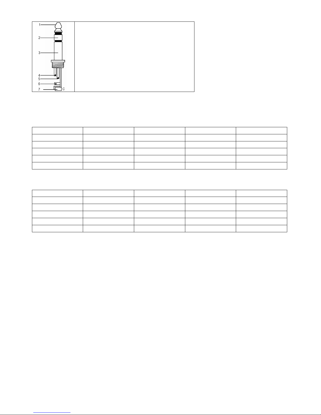
PROMIX66/88 31 VELLEMAN
Symmetrische Stereo-1/4” Stecker
1. Spitze = heiß (+)
2. Ring = kalt (-)
3. Hülse = Erdung
4. Spitze
5. Ring
6. Hülse
7. Zugentlastungsklemme
5. Technische Daten
Eingang
Eingang Anschluss Eingangsimpedanz Nominalpegel Max. Pegel
MONO CH MIC XLR > 1.3K Ohm +2dBm +14dBm
MONO CH LINE ¼” TRS > 10K Ohm +4dBm +22dBm
STEREO CH LINE ¼” TRS > 10K Ohm +4dBm +22dBm
TAPE IN RCA PIN JACKS > 10K Ohm +2dBm +22dBm
AUX RETURNS ¼” TRS > 10K Ohm +4dBm +22dBm
Ausgang
Ausgang Anschluss Eingangsimpedanz Nominalpegel Max. Pegel
STEREO OUT L/R ¼” TRS 120 Ohm +4~6dBm +22dBm
AUX SEND ¼” TRS 120 Ohm +4~6dBm +20dBm
CTRL R OUT ¼” TRS 120 Ohm +4~6dBm +22dBm
REC OUT RCA PIN JACKS 1K Ohm +4~6dBm +22dBm
PHONES ¼” TRS 100 Ohm - 40mW * 2
Frequenzbereich 20Hz bis 20KHz
THD 0.02%, 20Hz~20KHz @ 1KHz, 0dBm
Equalizer Eingangskanal
High 12KHz, +/- 15dB, Q fest auf 2 Oktaven
Mid 2.5KHz, +/- 15dB, Q fest auf eine 1 Oktave
Low 80Hz, +/- 15dB, Q fest auf 2 Oktaven
Verstärkungsbereich
Trimm-Regelung Eingangskanal Stopp bis Stopp, MIC +10dB~+60dB
LINE +10dB~+40dB
Kanal/Master/Effekt Faders -∞ bis +15dB
Aux Send/Aux Master Send OFF bis+15dB
Aux Return OFF bis +20dB
Kanal und Master Effects Send OFF bis +15dB
Crosstalk @ 1KHz -78dB~-68dB
Brummton und Geräusch 20Hz-20KHz, Rs = 150 Ohm, Eingang TRIMM @ 0dB, Empfindlichkeit
@ -60dB
Äquivalent Eingangsrauschen -129dBm
Ausgangsrauschen <90dBm
VU-Meter 10-Segment LED x 2
Phantomspeisung +48VDC
Stromversorgung 120VAC / 60Hz oder 230VAC / 50Hz wählbar
Stromaufnahme 25W
Page 32

PROMIX66/88 32 VELLEMAN
Abmessungen
PROMIX66 253 x 236 x 55mm
PROMIX88 253 x 290 x 55mm
Gewicht
PROMIX66 1.72kg
PROMIX88 2kg
Alle Änderungen vorbehalten.
PROMIX66/88 – PROFESJONALNY MIKSER 6-cio/8-mio KANAŁOWY
1. Wprowadzenie.
Przeznaczona dla mieszkańców Unii Europejskiej.
Ważne informacje dotyczące środowiska.
Ten symbol umieszczony na urządzeniu bądź opakowaniu wskazuje, że wyrzucenie produktu może być
szkodliwe dla środowiska i nie należy go traktować jako odpad komunalny. Nie wyrzucaj urządzenia lub
baterii do zbiorczego śmietnika, tylko do specjalnie przeznaczonych do tego pojemników na urządzenia
elektroniczne lub skontaktuj się z firmą zajmującą się recyklingiem.
Urządzenie możesz oddać dystrybutorowi lub firmie zajmującej się recyklingiem. Postępuj zgodnie z zasadami
bezpieczeństwa dotyczącymi środowiska. Jeśli masz wątpliwości skontaktuj się z firmą zajmującą się utylizacją
odpadów
Dziękujemy za wybór produktu HQPOWER. Prosimy o dokładne zapoznanie się z instrukcją obsługi przed użyciem.
Jeśli urządzenie zostało uszkodzone podczas transportu prosimy o nie korzystanie z niego i skontaktowanie się ze
sprzedawcą.
2. Instrukcje bezpieczeństwa, środki ostrożności
• Wszelkie szkody spowodowane użytkowaniem niezgodnym z niniejszą instrukcją nie są objęte gwarancją, a
sprzedawca nie ponosi za nie odpowiedzialności.
• Montaż oraz naprawy powinny być przeprowadzone przez wykwalifikowany personel techniczny.
• Nie włączać urządzenia, gdy było ono narażone na duże zmiany temperatury. Przed włączeniem należy
odczekać, aż urządzenie osiągnie temperaturę otoczenia.
• Nie narażać urządzenia na działanie cieczy. Należy zadbać, aby powyżej urządzenia nie znajdowały się żadne
naczynia z płynami mogącymi zalać urządzenie.
• Wszelkie szkody powstałe na skutek samodzielnej modyfikacji przez użytkownika nie są objęte gwarancją.
• Chronić przed dziećmi oraz użytkownikami nieautoryzowanymi.
3. Opis produktu.
MONO Input Chanel.
1. MIC Input – wejście mikrofonowe.
Każdy kanał wejścia MIC oferuje monofoniczne symetryczne (zrównoważone) wejście mikrofonowe przez
gniazdo XLR z funkcje zasilania +48VDC phantom dla mikrofonów pojemnościowych. Rozkład pinów gniazda
XLR: Pin 1 (masa), Pin 2 (dodatni (+)),Pin 3 (ujemne (-)).
Proszę zachować wszelką ostrożność podczas instalacji urządzenia. Bezpośrednie dotknięcie elementów
będących pod napięciem grozi porażeniem wysokim napięciem.
Chronić przed deszczem, wilgocią, oblaniem oraz innym kontaktem z cieczami.
Przed otworzeniem obudowy odłączyć urządzenie z sieci energetycznej.
Page 33

PROMIX66/88 33 VELLEMAN
2. LINE IN wejście liniowe.
Każde wejście linowe monofoniczne jest tak zaprojektowane, że akceptuje sygnał
symetryczny jak również asymetryczny takie jak np. instrumenty klawiszowe, automaty
perkusyjne czy samplery. Do wejścia liniowego możesz podłączyć nawet sygnały o
bardzo niskim poziomie jak mikrofon czy gitara (mogą być sygnały asymetryczne).
Wejście LINE wykonane w formie gniazda 6,3 mm typu „Jack“. Do wejścia LINE można
podłączyć sygnał symetryczny. W tym celu należy użyć trójpolowy wtyk Jack 6,3mm.
Rozkład pinów wtyku Jack 6,3mm: końcówka - dodatni (+), pierścień - ujemne (-), tuleja
(masa ).
UWAGA: W danej chwili można używać jedynie albo wejścia mikrofonowego MIC albo
wejścia LINE, ale nigdy obu jednocześnie.
3. TRIM Control – regulacja czułości wejść MIC / LINE.
Regulator TRIM reguluje czułość wejść MIC / LINE dla każdego kanału monofonicznego.
Dzięki funkcji TRIM z łatwością można dopasować każde źródło sygnału od tych z
wysokim poziomem np. instrumenty klawiszowe, automaty perkusyjne czy samplery po
źródła dostarczające niski poziom sygnału jak mikrofony. Szeroki zakres regulacji
eliminuje potrzebę przełączania wejść MIC / LINE. Najlepszy odstęp sygnału od szumu
S/N oraz wysoki poziom dynamiki zostanie osiągnięty wtedy, gdy regulacja TRIM będzie
przeprowadzona dla każdego kanału osobno, zwracając uwagę, aby dioda PEAK LED
(7) zapalała się sporadycznie.
UWAGA: Zawsze, gdy podłączasz lub odłączasz źródło sygnału od wejść MIC / LINE
regulator TRIM musi byś skręcony do oporu w lewo.
4. EQUALIZER Controls – regulacja barwy dźwięku.
Wszystkie monofoniczne wejścia wyposażone są w trzypasmową regulacje barwy
dźwięku, która pozwala na podbicie lub stłumienie sygnału +/- 15dB. W pozycji środkowej
korektor jest neutralny 0 dB. Częstotliwość graniczna korektora górnego pasma (HIGH )
wynosi 12kHz, natomiast dolnego 80Hz.
5. AUX / EFF SEND Control
Regulator AUX / EFF kontroluje poziom sygnału, który jest pobierany za equalizerem i
regulatorem CHANNEL GAIN Control (8). Konfiguracja wyjścia AUX daje szereg
możliwości monitorowania dźwięku w studiu nagraniowym czy na scenie. Regulatory EFF
kontrolują poziom każdego sygnału wychodzącego z kanałów miksera, które są wysyłane na
wewnętrzną magistralę do wbudowanego procesora sygnałowego DSP (Digital Sound
Processor).
6. PAN Control – regulacja położenia sygnału.
Regulacja PAN okreś
la położenie sygnału wejścia MIC/LINE w panoramie przestrzeni
stereo. Regulacja ta charakteryzuje się tym, iż sygnał posiada stałą moc i poziom w
panoramie przestrzeni stereo niezależnie od jego przesunięcia.
7. PEAK Indicator – wskaźnik poziomu sygnału.
Dioda LED sygnalizuje zbyt wysoki poziom sygnału po wyjściu z equalizera. Dioda zapala
się, gdy poziom sygnału jest na poziomie -3 dB przed przesterowaniem. Dioda może się
zapalać okazjonalnie, jednak, gdy świeci cały czas lub niemal cały czas należy zmniejszyć
poziom sygnału regulatorem TRIM Control (3).
8. CHANNEL GAIN Control – regulator poziomu sygnału.
Regulator kontroluje poziom sygnału kanału MIC/LINE wchodzącego na MASTER MIX.
Mikser nie posiada funkcji PFL, a zatem, aby odsłuchać dźwięk z kanału MIC/LINE należy
pozostałe regulatory LEVEL innych kanałów skręcić maksymalnie w lewo. Regulator LEVEL
oraz MASTER MIX (29) należ
y ustawić w pozycji środkowej 0dB. Diodowy miernik poziomu
sygnału (21) powinien wskazywać poziom 0dB LEVEL.
Page 34

PROMIX66/88 34 VELLEMAN
STEREO Input Channel (rysunek 2).
4. EQUALIZER Controls.
Regulacja barwy dźwięku działa w identyczny sposób jak w torze monofonicznym. Wszystkie regulacje odbywają
się współbieżnie dla kanału lewego i prawego. Preferuje się stosowanie korektora stereo zamiast dwóch mono
ponieważ w ten sposób unika się rozbieżności podczas regulacji pomiędzy kanałami.
5. AUX / EFF SEND Control.
Posiada dokładnie taką samą funkcjonalność jak w torze monofonicznym.
8. CHANNEL GAIN CONTROL – regulator poziomu sygnału..
Regulator kontroluje poziom sygnału kanału MIC/LINE wchodzącego na MASTER MIX. Mikser nie posiada funkcji
PFL, a zatem aby odsłuchać dźwięk z kanału MIC/LINE należy pozostałe regulatory LEVEL innych kanałów
skręcić maksymalnie w lewo. Regulator CHANNEL GAIN Control (8) oraz MASTER MIX (21) należy ustawić w
pozycji środkowej 0dB. Diodowy miernik poziomu sygnału (21) powinien wskazywać poziom 0dB LEVEL.
9. LINE IN – wejście liniowe.
Każde stereofoniczne wejście linowe monofoniczne ma dwa symetryczne wejścia wykonane w formie gniazda 6,3
mm typu „jack“. Dla każdego kanału lewego i prawego oddzielnie. Jeżeli używane jest tylko gniazdo oznaczone
jako "L", kanał pracuje jako monofoniczny. Kanały stereofoniczne przystosowane są do pracy z sygnałami o
poziomie LINE. Oba gniazda mogą pracować symetrycznie lub asymetrycznie. Sygnał symetryczny doprowadza
się według schematu: Rozkład pinów wtyku Jack 6,3mm: końcówka - dodatni (+),pierścień - ujemne (-) ,tuleja
(masa ).
10.BAL Control – regulacja balansu.
W przypadku, gdy sygnał doprowadzony jest tylko do lewego kanału regulator BAL (9) przyjmuje funkcję PAN (5).
Jednak gdy kanał pracuje w trybie stereofonicznym wtedy regulator BAL (9) ustala względny udział pomiędzy
lewym, a prawym sygnałem wejścia liniowego przed doprowadzeniem sygnałów na szyny sygnałowe MASTER
MIX. Jeżeli regulator BAL (9) zostanie maksymalnie skręcony w prawo to tylko sygnał z kanału prawego zostanie
skierowany na szynę sygnału MASTER MIX.
PANEL GŁÓWNY (rysunek 3 & 4)
11. STEREO AUX RETURNS (LEFT / MONO, RIGHT) – wejścia sygnałów efektowych.
Gniazda typu Jack 6,3mm AUX RETURN można użyć jako mono lub stereo do podłączenia sygnału z wyjścia
efektów AUX SEND lub dodatkowego źródła z wyjściem liniowym. Jeżeli tylko podłączysz sygnał do LEFT /
MONO RETURN to AUX RETURN będzie działać w trybie mono i sygnał będzie przesyłany do regulatora AUX
RETURN (19). Następnie zmiksowany pomiędzy kanałami lewym, a prawym w Master Mix i skierowany na
wyjścia stereo (13). Jeżeli jednak podłączysz sygnał stereo do obu wejść kanału lewego i prawego to sygnały
zostaną przesłane regulatora AUX RETURN (19), a następnie zmiksowane pomiędzy kanałami lewym, a prawym
w Master Mix i skierowany na wyjścia stereo (13) z zachowaniem pełnej separacji kanałów.
Page 35

PROMIX66/88 35 VELLEMAN
12. AUX SEND - wyjście sygnału.
Wyjście AUX SEND do wysyłające sygnał do urządzenia efektowego. Poziom sygnał na wyjściu AUX SEND jest
kontrolowany przez regulatory AUX / EFF controls (5) oraz AUX SEND controls (18). Wyjście AUX SEND
wykonane jest jako gniazd monofoniczne ( asymetrycznych) typu Jack 6,3mm. Wyprowadzenia sygnału w
gniazdach: końcówka - dodatni (+), tuleja (masa ). Sygnał może wykorzystany przez urządzenia typu: procesor
efektów, rejestrator wielościeżkowy lub wiele innych urządzeń akceptujących sygnał o poziomie LINE.
13. STEREO Outputs – wyjście stereofoniczne.
Wyjście to wyprowadza sygnał główny do zewnętrznego wzmacniacza mocy. Wyjście stereofoniczne STREO
OUTPUT wykonane jest jako para gniazd monofonicznych ( asymetrycznych) typu Jack 6,3mm. Wyprowadzenia
sygnału w gniazdach: końcówka - dodatni (+), tuleja (masa ).
14. TAPE Inputs – wejście magnetofonowe.
Wejście magnetofonowe TAPE INPUT służy do przyłączenia zewnętrznego źródła w postaci magnetofonu.
Wyście wykonane jest jako para gniazd RCA.
15. REC Outputs – wyjście magnetofonowe.
Wyjście magnetofonowe REC OUTPUT wyprowadza stereofoniczny sygnał MASTER MIX. Wyjścia to służy do
podłączenia urządzeń rejestrujących dźwięk. Wyjście wykonane jest jako para gniazd RCA.
16. L-R Control Room Outputs wyjście do monitora.
Wyjście L-R control room outputs służy do podłączania wzmacniacza systemu odsłuchowego lub innego systemu
monitorującego. Wykonane jest jako podwójne gniazdo monofoniczne typu Jack 6,3mm. Wyprowadzenia
sygnału w gnieździe: końcówka sygnał, tuleja (masa )
17. PHONES Output – wyjście słuchawkowe.
Wyjście słuchawkowe służy do podsłuchu za MASTER MIX. Wykonane jest jako gniazdo typu Jack 6,3mm.
Wyprowadzenia sygnału w gnieździe: końcówka kanał lewy, pierścień kanał prawy, tuleja (masa ).
18. AUX SEND - regulacja poziomu sygnału wysyłanego na efekt.
Regulacja poziomu sygnału dostępnego na złączu typu jack 6,3mm AUX SEND (12).
19. AUX RETURN Control - regulacja poziomu sygnału wyjściowego.
Regulacja poziomu sygnału dostępnego na złączach typu jack 6,3mm STEREO OUT (13).
20. PHONES/CONTROL ROOM CONTROL-
regulacja głośności na wyjściach
odsłuchowych CONTROL ROOM (16) oraz
HEADPHONES (17).
21. LED OUTPUT Meter - 10-cio segmentowy
diodowy LED wskaźnik poziomu sygnału
MASTER MIX.
22. PHANTOM POWER ON/OFF Switch –
włącznik zasilana phantom +48VDC.
Kiedy używasz mikrofonu pojemnościowego
wymagane jest włączenie napięcia zasilania
+48VDC. Zasilanie phantomowe włącza się
przy pomocy włącznika PHANTOM POWER
ON/OFF, co jest sygnalizowane świeceniem
diody LED PHANTOM POWER ON LED (25).
Zasilanie +48VDC pojawia się na obu
kanałach mono MIC XLR na pinie 3. Jeżeli
nie potrzebujesz zasilania phantom zawsze
wyłącz zasilanie.
UWAGA: Przy włączonym zasilaniu 48VDC
nie ma ryzyka uszkodzenia urządzeń z
wyjściem symetrycznym. Jednak w
przypadku urządzeń z wyjście
niesymetrycznym lub symetrycznym
transformatorem na wyjściu istnieje ryzyko ich
uszkodzenia, a głośniku może pojawić się
brzęczenie. Zwarcie +48VDC może uszkodzić
Page 36

PROMIX66/88 36 VELLEMAN
mikser. Aby zapobiec trzaskowi podczas włączania +48VDC, należy włączyć zasilanie phantom przy wyłączonym
mikserze lub skręconych na minimum regulatorze MASTER MIX (29) lub regulatorów TRIM (3).
23. TAPE / REC TO CONTROL ROOM Switch.
Jeżeli przycisk TAPE / REC TO CONTOL ROOM jest wciśnięty, sygnał z gniazd TAPE input (14) zostanie
przełączony na PHONES / CONTROL ROOM (20).
24. TAPE / REC TO MASTER Switch.
Jeżeli przycisk TAPE / ECHO TO MASTER jest wciśnięty, sygnał z gniazd TAPE input (14) zostanie przełączony
na MASTER MIX GAIN (29).
25. PHANTOM POWER LED
Czerwona dioda LED +48V świeci gdy zasilanie phantom jest włączone.
26. POWER ON LED - kontrolka zasilania LED.
Świecenie dioda LED POWER ON LED sygnalizuje, że mikser jest włączony.
DIGITAL EFFECTS Section
27. EFFECTS Display – wyświetlacz numeru efektu dźwiękowego.
Naciskając przyciski wyboru efektu ECHO na wyświetlaczu będzie widoczny numer efektu w zakresie 1 – 16.
28. ECHO EFFECT SELECT Buttons
Wbudowany procesor dźwięku DSP oferuje 16 różnych efektów Echo zróżnicowanych ze względu na poziom
sygnału jak i parametry czasowe. Efekty wybiera się przy pomocy przycisków UP / DOWN. Procesor dźwięku
DSP przetwarza sygnał z szyny EFFECTS BUS, a następnie kieruje na kanały mono i stereo, kontrolowane przez
regulatory EFF (5).
29. MASTER MIX GAIN Control– główny regulator poziomu sygnału wyjściowego z miksera.
Regulator MASTER MIX GAIN Control reguluje poziom sygnału na wyjściach STEREO OUTPUTS oraz REC
OUTPUT.
30. EFFECT SEND – regulator poziomu sygnału do procesora DSP
Regulacja poziomu sygnału wysyłanego na szynę efektów dźwiękowych w procesorze dźwiękowym DSP.
31. EFFECT (ECHO) RETURN – regulator ilości powtórzeń
Regulacja ilości powtórzeń efektu ECHO. Wybór efektu przy pomocy przycisków UP / DOWN (28).
32. EFFECT GAIN
Regulacja poziomu sygnału wychodzącego z procesora DSP, który jest kierowany na szynę MASTER MIX.
Tylna ścianka miksera (rysunek 5)
33. AC POWER IN – gniazdo zasilania miksera
Podłącz 3-pinowy wtyk zasilacza do gniazda zasilania miksera, a następnie zasilacz do sieci energetycznej.
34. MAIN POWER Switch – włącznik zasilania miksera.
Przy pomocy tego włącznika włącza się i wyłącza mikser. Włącznik w pozycji ON załącza zasilanie miksera.
UWAGA: Pamiętaj aby przed włączeniem zasilania miksera był on połączony całkowicie z systemem
nagłaśniającym. (Zaleca się przekręcenie regulatora MASTER MIX maksymalnie w lewą stronę).
4. Złącza.
Do miksera można podłączać urządzenia z sygnałem niesymetrycznym. W tym celu należy stosować
monofoniczne wtyki typu Jack 6,3mm lub w przypadku stosowania wtyków stereofonicznych połączyć
pierścień z tuleją masową wtyczki.
Page 37

PROMIX66/88 37 VELLEMAN
Nigdy nie używać połączeń asymetrycznych przy wejściu MIC w przypadku gdy ma być stosowany
mikrofon z zasilaniem phantom.
5. Specyfikacja techniczna
INPUT - wejścia
Wejście Złącze Impedancja
wejściowa
Poziom nominalny Poziom
maksymalny
MONO CH MIC XLR > 1.3K ohms +2dBm +14dBm
Słuchawki
1. Końcówka = sygnał kanału lewego.
2. Pierścień. = sygnał kanału prawego.
3. Tulejka = masa.
4. Końcówka
5. Pierścień.
6. Tulejka
7. Uchwyt przewodu.
Podłączenie sygnału asymetrycznego Jack 6,3mm mono
1. Końcówka = sygnał
2. Tulejka = masa.
3. Końcówka
4. Tulejka
5. Uchwyt przewodu.
Podłączenie sygnału symetrycznego Jack 6,3mm stereo
1. Końcówka = gorący (+)
2. Pierścień. = zimny (-)
3. Tulejka = masa.
4. Końcówka
5. Pierścień.
6. Tulejka
7. Uchwyt przewodu.
Microphone input Group & mix outputs
Gniazdo Wtyk
Page 38

PROMIX66/88 38 VELLEMAN
MONO CH LINE ¼” TRS > 10K ohms +4dBm +22dBm
STEREO CH LINE ¼” TRS > 10K ohms +4dBm +22dBm
TAPE IN RCA PIN JACKS > 10K ohms +2dBm +22dBm
AUX RETURNS ¼” TRS > 10K ohms +4dBm +22dBm
OUTPUT – wyjścia
Wejście Złącze Impedancja
wejściowa
Poziom nominalny Poziom
maksymalny
STEREO OUT L/R ¼” TRS 120 ohms +4~6dBm +22dBm
AUX SEND ¼” TRS 120 ohms +4~6dBm +20dBm
CTRL R OUT ¼” TRS 120 ohms +4~6dBm +22dBm
REC OUT RCA PIN JACKS 1K ohms +4~6dBm +22dBm
PHONES ¼” TRS 100 ohms - 40mW * 2
Pasmo przenoszenia 20Hz to 20KHz
Zniekształcenia THD 0.02%, 20Hz~20KHz @ 1KHz, 0dBm
Podział equalizera
High - górne 12KHz, +/- 15dB, Q 2 oktawy
Mid - żsrodkowe 2.5KHz, +/- 15dB, Q 1 octawa
Low - dolne 80Hz, +/- 15dB, Q 2 octawy
Zakresy regulacji poszczególnych elementów
Input Channel Trim Control stop to stop, MIC +10dB~+60dB
LINE +10dB~+40dB
Channel/Master/Effect Faders -∞ to +15dB
Aux Send/Aux Master Send -∞ to +15dB
Aux Return -∞ to +20dB
Channel and Master Effects Send -∞ to +15dB
Przesłuchy @ 1KHz -78dB~-68dB
Szumy 20Hz-20KHz, Rs = 150 ohms, input TRIM @ 0dB, sensitivity at -60dB
Poziom szumów na wejściu EIN -129dBm
Residual Output Noise <90dBm
Wskaźnik wysterowania VU 10-segment LED x 2
ZasilaniePhantom +48VDC
Zasilanie 120VAC / 60Hz or 230VAC / 50Hz selectable
Pobór mocy 25W
Wymiary
PROMIX66 253 x 236 x 55mm
PROMIX88 253 x 290 x 55mm
Waga
PROMIX66 1.72kg
PROMIX88 2kg
Informacje zawarte w niniejszym instrukcji mogą ulec zmianie bez uprzedzenia.
Page 39

Velleman® Service and Quality Warranty
Velleman® has over 35 years of experience in the electronics world and
distributes its products in more than 85 countries.
All our products fulfil strict quality requirements and legal stipulations in the
EU. In order to ensure the quality, our products regularly go through an extra
quality check, both by an internal quality department and by specialized
external organisations. If, all precautionary measures notwithstanding,
problems should occur, please make appeal to our warranty (see guarantee
conditions).
General Warranty Conditions Concerning Consumer Products (for
EU):
• All consumer products are subject to a 24-month warranty on production
flaws and defective material as from the original date of purchase.
• Velleman® can decide to replace an article with an equivalent article, or to
refund the retail value totally or partially when the complaint is valid and a
free repair or replacement of the article is impossible, or if the expenses are
out of proportion.
You will be delivered a replacing article or a refund at the value of 100% of
the purchase price in case of a flaw occurred in the first year after the date of
purchase and delivery, or a replacing article at 50% of the purchase price or a
refund at the value of 50% of the retail value in case of a flaw occurred in the
second year after the date of purchase and delivery.
• Not covered by warranty:
- all direct or indirect damage caused after delivery to the article (e.g. by
oxidation, shocks, falls, dust, dirt, humidity...), and by the article, as well as
its contents (e.g. data loss), compensation for loss of profits;
- frequently replaced consumable goods, parts or accessories such as
batteries, lamps, rubber parts, drive belts... (unlimited list);
- flaws resulting from fire, water damage, lightning, accident, natural
disaster, etc.;
- flaws caused deliberately, negligently or resulting from improper handling,
negligent maintenance, abusive use or use contrary to the manufacturer’s
instructions;
- damage caused by a commercial, professional or collective use of the article
(the warranty validity will be reduced to six (6) months when the article is
used professionally);
- damage resulting from an inappropriate packing and shipping of the article;
- all damage caused by modification, repair or alteration performed by a third
party without written permission by Velleman®.
• Articles to be repaired must be delivered to your Velleman® dealer, solidly
packed (preferably in the original packaging), and be completed with the
original receipt of purchase and a clear flaw description.
• Hint: In order to save on cost and time, please reread the manual and
check if the flaw is caused by obvious causes prior to presenting the article
for repair. Note that returning a non-defective article can also involve
handling costs.
• Repairs occurring after warranty expiration are subject to shipping costs.
• The above conditions are without prejudice to all commercial warranties.
The above enumeration is subject to modification according to the article (see
article’s manual).
Velleman® service- en kwaliteitsgarantie
Velleman® heeft ruim 35 jaar ervaring in de elektronicawereld en verdeelt in
meer dan 85 landen.
Al onze producten beantwoorden aan strikte kwaliteitseisen en aan de
wettelijke bepalingen geldig in de EU. Om de kwaliteit te waarborgen,
ondergaan onze producten op regelmatige tijdstippen een extra
kwaliteitscontrole, zowel door onze eigen kwaliteitsafdeling als door externe
gespecialiseerde organisaties. Mocht er ondanks deze voorzorgen toch een
probleem optreden, dan kunt u steeds een beroep doen op onze waarborg
(zie waarborgvoorwaarden).
Algemene waarborgvoorwaarden consumentengoederen (voor
Europese Unie):
• Op alle consumentengoederen geldt een garantieperiode van 24 maanden
op productie- en materiaalfouten en dit vanaf de oorspronkelijke
aankoopdatum.
• Indien de klacht gegrond is en een gratis reparatie of vervanging van een
artikel onmogelijk is of indien de kosten hiervoor buiten verhouding zijn, kan
Velleman
®
beslissen het desbetreffende artikel te vervangen door een
gelijkwaardig artikel of de aankoopsom van het artikel gedeeltelijk of volledig
terug te betalen. In dat geval krijgt u een vervangend product of
terugbetaling ter waarde van 100% van de aankoopsom bij ontdekking van
een gebrek tot één jaar na aankoop en levering, of een vervangend product
tegen 50% van de kostprijs of terugbetaling van 50% bij ontdekking na één
jaar tot 2 jaar.
• Valt niet onder waarborg:
- alle rechtstreekse of onrechtstreekse schade na de levering veroorzaakt aan
het toestel (bv. door oxidatie, schokken, val, stof, vuil, vocht...), en door het
toestel, alsook zijn inhoud (bv. verlies van data), vergoeding voor eventuele
winstderving.
- verbruiksgoederen, onderdelen of hulpstukken die regelmatig dienen te
worden vervangen, zoals bv. batterijen, lampen, rubberen onderdelen,
aandrijfriemen... (onbeperkte lijst).
- defecten ten gevolge van brand, waterschade, bliksem, ongevallen,
natuurrampen, enz.
- defecten veroorzaakt door opzet, nalatigheid of door een onoordeelkundige
behandeling, slecht onderhoud of abnormaal gebruik of gebruik van het
toestel strijdig met de voorschriften van de fabrikant.
- schade ten gevolge van een commercieel, professioneel of collectief gebruik
van het apparaat (bij professioneel gebruik wordt de garantieperiode herleid
tot 6 maand).
- schade veroorzaakt door onvoldoende bescherming bij transport van het
apparaat.
- alle schade door wijzigingen, reparaties of modificaties uitgevoerd door
derden zonder toestemming van Velleman
®
.
• Toestellen dienen ter reparatie aangeboden te worden bij uw Velleman®verdeler. Het toestel dient vergezeld te zijn van het oorspronkelijke
aankoopbewijs. Zorg voor een degelijke verpakking (bij voorkeur de originele
verpakking) en voeg een duidelijke foutomschrijving bij.
• Tip: alvorens het toestel voor reparatie aan te bieden, kijk nog eens na of
er geen voor de hand liggende reden is waarom het toestel niet naar behoren
werkt (zie handleiding). Op deze wijze kunt u kosten en tijd besparen. Denk
eraan dat er ook voor niet-defecte toestellen een kost voor controle
aangerekend kan worden.
• Bij reparaties buiten de waarborgperiode zullen transportkosten
aangerekend worden.
• Elke commerciële garantie laat deze rechten onverminderd.
Bovenstaande opsomming kan eventueel aangepast worden
naargelang de aard van het product (zie handleiding van het
betreffende product).
Garantie de service et de qualité Velleman®
Velleman® jouit d’une expérience de plus de 35 ans dans le monde de
l’électronique avec une distribution dans plus de 85 pays.
Tous nos produits répondent à des exigences de qualité rigoureuses et à des
dispositions légales en vigueur dans l’UE. Afin de garantir la qualité, nous
soumettons régulièrement nos produits à des contrôles de qualité
supplémentaires, tant par notre propre service qualité que par un service
qualité externe. Dans le cas improbable d’un défaut malgré toutes les
précautions, il est possible d’invoquer notre garantie (voir les conditions de
garantie).
Conditions générales concernant la garantie sur les produits grand
public (pour l’UE) :
• tout produit grand public est garanti 24 mois contre tout vice de production
ou de matériaux à dater du jour d’acquisition effective ;
• si la plainte est justifiée et que la réparation ou le remplacement d’un article
est jugé impossible, ou lorsque les coûts s’avèrent disproportionnés,
Velleman® s’autorise à remplacer ledit article par un article équivalent ou à
rembourser la totalité ou une partie du prix d’achat. Le cas échéant, il vous
sera consenti un article de remplacement ou le remboursement complet du
prix d’achat lors d’un défaut dans un délai de 1 an après l’achat et la
livraison, ou un article de remplacement moyennant 50% du prix d’achat ou
le remboursement de 50% du prix d’achat lors d’un défaut après 1 à 2 ans.
• sont par conséquent exclus :
- tout dommage direct ou indirect survenu à l’article après livraison (p.ex.
dommage lié à l’oxydation, choc, chute, poussière, sable, impureté…) et
provoqué par l’appareil, ainsi que son contenu (p.ex. perte de données) et
une indemnisation éventuelle pour perte de revenus ;
- tout bien de consommation ou accessoire, ou pièce qui nécessite un
remplacement régulier comme p.ex. piles, ampoules, pièces en caoutchouc,
courroies… (liste illimitée) ;
- tout dommage qui résulte d’un incendie, de la foudre, d’un accident, d’une
catastrophe naturelle, etc. ;
- tout dommage provoqué par une négligence, volontaire ou non, une
utilisation ou un entretien incorrect, ou une utilisation de l’appareil contraire
aux prescriptions du fabricant ;
- tout dommage à cause d’une utilisation commerciale, professionnelle ou
collective de l’appareil (la période de garantie sera réduite à 6 mois lors d’une
utilisation professionnelle) ;
- tout dommage à l’appareil qui résulte d’une utilisation incorrecte ou
différente que celle pour laquelle il a été initialement prévu comme décrit
dans la notice ;
- tout dommage engendré par un retour de l’appareil emballé dans un
conditionnement non ou insuffisamment protégé ;
- toute réparation ou modification effectuée par une tierce personne sans
l’autorisation explicite de SA Velleman® ;
- frais de transport de et vers Velleman® si l’appareil n’est plus couvert sous
la garantie.
• toute réparation sera fournie par l’endroit de l’achat. L’appareil doit
nécessairement être accompagné du bon d’achat d’origine et être dûment
conditionné (de préférence dans l’emballage d’origine avec mention du
défaut) ;
• conseil : il est conseillé de consulter la notice et de contrôler câbles, piles,
etc. avant de retourner l’appareil. Un appareil retourné jugé défectueux qui
s’avère en bon état de marche pourra faire l’objet d’une note de frais à
charge du consommateur ;
• une réparation effectuée en-dehors de la période de garantie fera l’objet de
frais de transport ;
• toute garantie commerciale ne porte pas atteinte aux conditions
susmentionnées.
La liste susmentionnée peut être sujette à une complémentation
selon le type de l’article et être mentionnée dans la notice d’emploi.
Garantía de servicio y calidad Velleman®
Velleman® disfruta de una experiencia de más de 35 años en el mundo de la
electrónica con una distribución en más de 85 países.
Todos nuestros productos responden a normas de calidad rigurosas y
disposiciones legales vigentes en la UE. Para garantizar la calidad, sometimos
nuestros productos regularmente a controles de calidad adicionales, tanto por
nuestro propio servicio de calidad como por un servicio de calidad externo. En
el caso improbable de que surgieran problemas a pesar de todas las
precauciones, es posible apelar a nuestra garantía (véase las condiciones de
garantía).
Condiciones generales referentes a la garantía sobre productos de
venta al público (para la Unión Europea):
• Todos los productos de venta al público tienen un período de garantía de 24
meses contra errores de producción o errores en materiales desde la
adquisición original;
• Si la queja está fundada y si la reparación o la sustitución de un artículo es
imposible, o si los gastos son desproporcionados, Velleman® autoriza
reemplazar el artículo por un artículo equivalente o reembolsar la totalidad o
una parte del precio de compra. En este caso, recibirá un artículo de recambio
o el reembolso completo del precio de compra al descubrir un defecto hasta
un año después de la compra y la entrega, o un artículo de recambio al 50%
del precio de compra o la sustitución de un 50% del precio de compra al
descubrir un defecto después de 1 a 2 años.
• Por consiguiente, están excluidos entre otras cosas:
- todos los daños causados directamente o indirectamente al aparato y su
contenido después de la entrega (p.ej. por oxidación, choques, caída,...) y
causados por el aparato, al igual que el contenido (p.ej. pérdida de datos) y
una indemnización eventual para falta de ganancias;
- partes o accesorios que deban ser reemplazados regularmente, como por
ejemplo baterías, lámparas, partes de goma, ... (lista ilimitada);
- defectos causados por un incendio, daños causados por el agua, rayos,
accidentes, catástrofes naturales, etc.;
Page 40

PROMIX66/88 40 VELLEMAN
- defectos causados a conciencia , descuido o por malos tratos, un
mantenimiento inapropiado o un uso anormal del aparato contrario a las
instrucciones del fabricante;
- daños causados por un uso comercial, profesional o colectivo del aparato (el
período de garantía se reducirá a 6 meses con uso profesional);
- daños causados por un uso incorrecto o un uso ajeno al que est está
previsto el producto inicialmente como está descrito en el manual del usuario;
- daños causados por una protección insuficiente al transportar el aparato.
- daños causados por reparaciones o modificaciones efectuadas por una
tercera persona sin la autorización explicita de SA Velleman®;
- se calcula gastos de transporte de y a Velleman® si el aparato ya no está
cubierto por la garantía.
• Cualquier reparación se efectuará por el lugar de compra. Devuelva el
aparato con la factura de compra original y transpórtelo en un embalaje
sólido (preferentemente el embalaje original). Incluya también una buena
descripción del defecto;
• Consejo: Lea el manual del usuario y controle los cables, las pilas, etc.
antes de devolver el aparato. Si no se encuentra un defecto en el artículo los
gastos podrían correr a cargo del cliente;
• Los gastos de transporte correrán a carga del cliente para una reparación
efectuada fuera del periode de garantía.
• Cualquier gesto comercial no disminuye estos derechos.
La lista previamente mencionada puede ser adaptada según el tipo de
artículo (véase el manual del usuario del artículo en cuestión)
Velleman® Service- und Qualitätsgarantie
Velleman® hat gut 35 Jahre Erfahrung in der Elektronikwelt und vertreibt
seine Produkte in über 85 Ländern.
Alle Produkte entsprechen den strengen Qualitätsforderungen und
gesetzlichen Anforderungen in der EU. Um die Qualität zu gewährleisten
werden unsere Produkte regelmäßig einer zusätzlichen Qualitätskontrolle
unterworfen, sowohl von unserer eigenen Qualitätsabteilung als auch von
externen spezialisierten Organisationen. Sollten, trotz aller
Vorsichtsmaßnahmen, Probleme auftreten, nehmen Sie bitte die Garantie in
Anspruch (siehe Garantiebedingungen).
Allgemeine Garantiebedingungen in Bezug auf Konsumgüter (für die
Europäische Union):
• Alle Produkte haben für Material- oder Herstellungsfehler eine
Garantieperiode von 24 Monaten ab Verkaufsdatum.
• Wenn die Klage berechtigt ist und falls eine kostenlose Reparatur oder ein
Austausch des Gerätes unmöglicht ist, oder wenn die Kosten dafür
unverhältnismäßig sind, kann Velleman® sich darüber entscheiden, dieses
Produkt durch ein gleiches Produkt zu ersetzen oder die Kaufsumme ganz
oder teilweise zurückzuzahlen. In diesem Fall erhalten Sie ein Ersatzprodukt
oder eine Rückzahlung im Werte von 100% der Kaufsumme im Falle eines
Defektes bis zu 1 Jahr nach Kauf oder Lieferung, oder Sie bekommen ein
Ersatzprodukt im Werte von 50% der Kaufsumme oder eine Rückzahlung im
Werte von 50 % im Falle eines Defektes im zweiten Jahr.
• Von der Garantie ausgeschlossen sind:
- alle direkten oder indirekten Schäden, die nach Lieferung am Gerät und
durch das Gerät verursacht werden (z.B. Oxidation, Stöße, Fall, Staub,
Schmutz, Feuchtigkeit, ...), sowie auch der Inhalt (z.B. Datenverlust),
Entschädigung für eventuellen Gewinnausfall.
- Verbrauchsgüter, Teile oder Zubehörteile, die regelmäßig ausgewechselt
werden, wie z.B. Batterien, Lampen, Gummiteile, Treibriemen, usw.
(unbeschränkte Liste).
- Schäden verursacht durch Brandschaden, Wasserschaden, Blitz, Unfälle,
Naturkatastrophen, usw.
- Schäden verursacht durch absichtliche, nachlässige oder unsachgemäße
Anwendung, schlechte Wartung, zweckentfremdete Anwendung oder
Nichtbeachtung von Benutzerhinweisen in der Bedienungsanleitung.
- Schäden infolge einer kommerziellen, professionellen oder kollektiven
Anwendung des Gerätes (bei gewerblicher Anwendung wird die
Garantieperiode auf 6 Monate zurückgeführt).
- Schäden verursacht durch eine unsachgemäße Verpackung und
unsachgemäßen Transport des Gerätes.
- alle Schäden verursacht durch unautorisierte Änderungen, Reparaturen oder
Modifikationen, die von einem Dritten ohne Erlaubnis von Velleman
®
vorgenommen werden.
• Im Fall einer Reparatur, wenden Sie sich an Ihren Velleman
®
-Verteiler.
Legen Sie das Produkt ordnungsgemäß verpackt (vorzugsweise die
Originalverpackung) und mit dem Original-Kaufbeleg vor. Fügen Sie eine
deutliche Fehlerumschreibung hinzu.
• Hinweis: Um Kosten und Zeit zu sparen, lesen Sie die Bedienungsanleitung
nochmals und überprüfen Sie, ob es keinen auf de Hand liegenden Grund
gibt, ehe Sie das Gerät zur Reparatur zurückschicken. Stellt sich bei der
Überprüfung des Geräts heraus, dass kein Geräteschaden vorliegt, könnte
dem Kunden eine Untersuchungspauschale berechnet.
• Für Reparaturen nach Ablauf der Garantiefrist werden Transportkosten
berechnet.
• Jede kommerzielle Garantie lässt diese Rechte unberührt.
Die oben stehende Aufzählung kann eventuell angepasst werden
gemäß der Art des Produktes (siehe Bedienungsanleitung des
Gerätes).
Velleman® usługi i gwarancja jakości
Velleman® ma ponad 35-letnie doświadczenie w świecie elektroniki.
Dystrybuujemy swoje produkty do ponad 85 krajów.
Wszystkie nasze produkty spełniają surowe wymagania jakościowe oraz
wypełniają normy i dyrektywy obowiązujące w krajach UE. W celu
zapewnienia najwyższej jakości naszych produktów, przechodzą one
regularne oraz dodatkowo wyrywkowe badania kontroli jakości, zarówno
naszego wewnętrznego działu jakości jak również wyspecjalizowanych firm
zewnętrznych. Pomimo dołożenia wszelkich starań czasem mogą pojawić się
problemy techniczne, prosimy odwołać się do gwarancji (patrz warunki
gwarancji).
Ogólne Warunki dotyczące gwarancji:
Wszystkie produkty konsumenckie podlegają 24-miesięcznej gwarancji na
wady produkcyjne i materiałowe od daty zakupu.
W przypadku, gdy usterka jest niemożliwa do usunięcia lub koszt usunięcia
jest nadmiernie wysoki Velleman® może zdecydować o wymianie artykułu na
nowy, wolny od wad lub zwrócić zapłaconą kwotę. Zwrot gotówki może
jednak nastąpić z uwzględnieniem poniższych warunków:
zwrot 100% ceny zakupu w przypadku, gdy wada wystąpiła w ciągu
pierwszego roku od daty zakupu i dostawy
wymiana wadliwego artykułu na nowy, wolny od wad z odpłatnością 50%
ceny detalicznej lub zwrot 50% kwoty ceny nabycia w przypadku gdy wada
wystąpiła w drugim roku od daty zakupu i dostawy.
Produkt nie podlega naprawie gwarancyjnej:
- gdy wszystkie bezpośrednie lub pośrednie szkody spowodowane są
działaniem czynników środowiskowych lub losowych (np. przez utlenianie,
wstrząsy, upadki, kurz, brud, ...), wilgotności;
- gwarant nie ponosi odpowiedzialności za szkody wynikających z utraty
danych;
- utrata zysków z tytułu niesprawności produktu; z gwarancji wyłaczone są
matriały eksploatacyjne: baterie, żarówki, paski napędowe, gumowe
elementy napędowe... (nieograniczona lista);
- usterka wynika z działania pożaru, zalania wszelkimi cieczami, uderzenia
pioruna, upadku lub klęski żywiołowej, itp.;
- usterka wynika z zaniedbań eksploatacyjnych tj. umyślne bądź nieumyślne
zaniechanie czyszczenia, konserwacji, wymiany materiałów ekspolatacyjnych,
niedbalstwa lub z niewłaściwego obchodzenia się lub niezgodnego
użytkowania z instrukcją producenta;
- szkody wynikające z nadmiernego użytkowania gdy nie jest do tego celu
przeznaczony tj. działalność komerycjna, zawodowa lub wspólne użytkowanie
przez wiele osób - okres obowiązywania gwarancji zostanie obniżony do 6
(sześć) miesięcy;
- Szkody wynikające ze źle zabezpieczonej wysyłki produktu;
- Wszelkie szkody spowodowane przez nieautoryzowaną naprawę,
modyfikację, przeróbkę produktu przez osoby trzecie jak również bez
pisemnej zgody firmy Velleman®.
Uszkodzony produkt musi zostać dostarczony do sprzedawcy Velleman®,
solidnie zapakowany (najlepiej w oryginalnym opakowaniu), wraz z
wyposażeniem z jakim produkt został sprzedany. W przypadku wysyłki
towaru w opakowaniu innym niż oryginalnym ryzyko usterki produktu oraz
tego skutki przechodzą na właściciela produktu. Wraz z niesprawnym
produktem należy dołączyć jasny i szczegółowy opis jego usterki, wady;
Wskazówka: Aby zaoszczędzić na kosztach i czasie, proszę szczegółowo
zapoznać się z instrukcja obsługi; czy przyczyną wady są okoliczności
techniczne czy też wynikaja wyłącznie z nieznajomości obsługi produktu. W
przypadku wysyłki sprawnego produktu do serwisu nabywca może zostać
obciążony kosztmi obsługi oraz transportu.
W przypadku napraw pogwarancyjnych lub odpłatnych klient ponosi
dodatkowo koszt wysyłki produktu do i z serwisu.
wymienione wyżej warunki są bez uszczerbku dla wszystkich komercyjnych
gwarancji.
Powyższe postanowienia mogą podlegać modyfikacji w zależności od
wyrobu (patrz art obsługi).
 Loading...