

Page 1

CAMCOLD7
MINI PAN/TILT DOME COLOR CAMERA
MINIATUUR KLEUREN DOMECAMERA - PAN/TILT
MINICAMÉRA DÔME COULEUR - PAN/TILT
PAN/TILT MINI-DOME-FARBKAMERA
MINICÁMARA DOMO COLOR PAN/TILT
USER MANUAL 3
GEBRUIKERSHANDLEIDING 8
NOTICE D’EMPLOI 13
MANUAL DEL USUARIO 18
BEDIENUNGSANLEITUNG 23
Page 2

Page 3
CAMCOLD7
00 (17/09/2008)
3
User manual
1.
Introduction
To all residents of the European Union
Important environmental information about this product
This symbol on the device or the package indicates that disposal of the device
after its lifecycle could harm the environment.
Do not dispose of the unit (or batteries) as unsorted municipal waste; it should
be taken to a specialized company for recycling.
This device should be returned to your distributor or to a local recycling service.
Respect the local environmental rules.
If in doubt, contact your local waste disposal authorities.
Thank you for choosing the Velleman
CAMCOLD7
! Please read the manual thoroughly before
bringing this device into service. If the device was damaged in transit, don't install or use it
and contact your dealer.
2.
Safety Instructions
Keep the device away from children and unauthorized users.
FOR INDOOR USE ONLY. Keep this device away from rain, moisture, humidity,
splashing or dripping liquids.
Risk of electric shock when opening the cover.
No user-serviceable parts inside. Refer to an authorized dealer for service and/or
spare parts.
• Damage caused by disregard of certain guidelines in this manual is not covered by the
warranty and the dealer will not accept responsibility for any ensuing defects or problems.
• Note that damage caused by user modifications to the device is not covered by the
warranty.
3.
General Guidelines
• Protect this device from shocks and abuse. Avoid brute force when operating the device.
• Protected the device against extreme heat (e.g. direct sunlight, heater …), dust and
moisture.
• Familiarise yourself with the functions of the device before actually using it.
• All modifications of the device are forbidden for safety reasons.
• Only use the device for its intended purpose. Using the device in an unauthorised way will
void the warranty.
4.
Features
• fashionable design and suitable size for various applications
• On-Screen Display (OSD) function
• remote control via RS-485 Pelco-P and Pelco-D interface
• control of up to 15 devices using IR wireless control kit
• auto scan function
• for indoor use only
Page 4
CAMCOLD7
00 (17/09/2008)
4
5.
Overview
6.
Configuration
•
Before installing the mini pan/tilt dome, it must be configured though setting the
dipswitches that are located inside the dome. To reach the dipswitches, open the dome by
rotating the transparent cover (2) clockwise and lifting it.
•
Be very careful not to touch any other part inside the housing while setting the switches,
as damage might occur.
•
SW1~SW4 are used to set the ID of the device, allowing for a system with up to 15
unique devices. However, when using the IR remote control device, only the 9 first
(lowest) IDs can be controlled.
•
SW5 and SW6 set the BAUD rate, SW7 the used protocol and SW8 sets the type of alarm
contact to normally open (N.O.) or normally closed (N.C.).
ID SW 1 SW 2 SW 3 SW 4
0 OFF OFF OFF OFF SW 5 SW 6 BAUD rate
1 ON OFF OFF OFF ON ON 2400
2 OFF ON OFF OFF OFF ON 4800
3 ON ON OFF OFF ON OFF 9600
4 OFF OFF ON OFF
5 ON OFF ON OFF
6 OFF ON ON OFF SW 7 Protocol
7 ON ON ON OFF ON Native
8 OFF OFF OFF ON
OFF PELCO
9 ON OFF OFF ON
10 OFF ON OFF ON
11 ON ON OFF ON SW 8 Alarm type
12 OFF OFF ON ON ON N.O.
13 ON OFF ON ON
OFF N.C.
14 OFF ON ON ON
15 ON ON ON ON
•
Close the dome by placing the transparent cover (2) back and turning it counter
clockwise. Secure the transparent cover by mounting a small screw in the hole in the
housing.
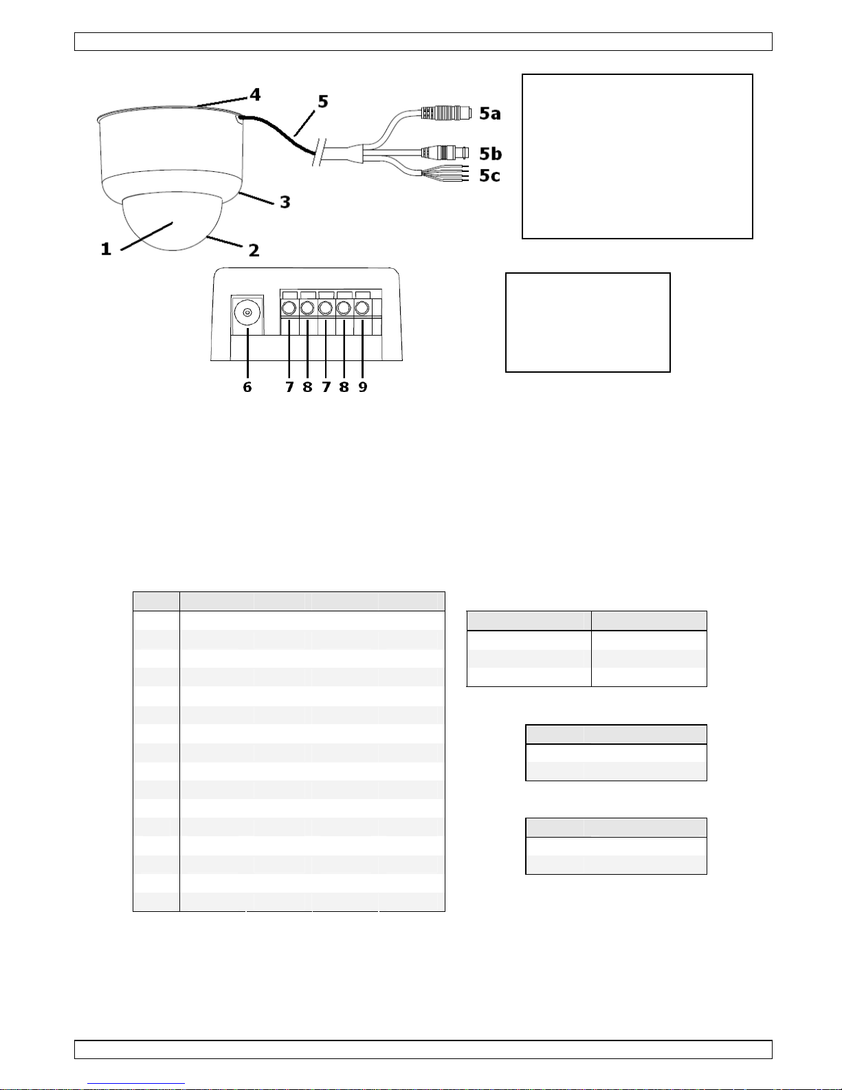
Dome
1. Camera
2. Transparent cover
3. Non-transparent housing
4. Mounting plate
5. Input/output cable
5a. video output (BNC)
5b. power input
5c. communication
IR receiver
6. DC power input
7. RS-485 D+
8. RS-485 D-
9. Ground
Page 5

CAMCOLD7
00 (17/09/2008)
5
7.
Installation
•
Remove the mounting plate (4) from the housing (3) by turning it clockwise and lifting it.
•
Fix the mounting plate (4) to the ceiling with 4 screws.
•
Attach the dome to the mounting plate (4). To do this, line up the pins on the mounting
plate (4) with the holes in the housing. Put the dome on the mounting plate (4) and
rotate counter clockwise to secure it.
•
Connect the video output (5a) to a monitor/DVR/multiplexer/….
•
Connect the communication cable (5c) to the IR receiver (7, 8 and 9):
Yellow lead Alarm input Green lead RS-485 D+
Blue lead Ground Red lead RS-485 D-
•
Use the yellow and blue leads to make a connection to the IR receiver and/or an existing
tamper switch (not incl.), motion sensor (not incl.), alarm system (not incl.), etc…. .
•
Provide power to the power input (5b) of the dome.
•
Connect a 12VDC/1A power supply (e.g. PS1210 - not included) to the DC power input
(6) of the IR receiver.
8.
Operation
•
After applying power to the mini dome, the camera will move to its initial position and the
system will be in standby mode.
•
To allow the controller to detect all connected mini pans/tilt domes, press [0] followed by
[ENTER]. After successful detection, the receiver box will produce a short beep. When
detection fails, a long beep followed by 3 short beeps will be produced.
Note: only the 9 lowest ID numbers can be controlled by the remote control.
•
Select the mini pan/tilt dome to be controlled by pressing the numeric button ([1]~ [9])
on the remote control, followed by [ENTER].
Note: there is no direct relationship between the entered number and the ID of the mini
pan/tilt dome. The dome with the lowest ID will be assigned to button [1] and so on.
•
To move the camera position, use the up/down/left/right keys on the remote control.
Note that only the camera direction will change, not the speed.
•
The mini pan/tilt dome can store 16 preset points which can be recalled instantly.
•
To configure a preset point, go to the desired dome and move to the desired camera
position with the up/down/left/right keys on the remote control. Enter a preset number by
pressing the desired number on the remote control followed by the [SET PRESET] button.
Follow the same procedure for more preset points. Entering an existing preset number
will override the previous preset point with the new configuration.
•
To recall a preset point, go to the desired dome and simply press the preset number
followed by the [GO PRESET] button on the remote control.
•
The mini pan/tilt dome contains an auto pan function. Depending on the chosen option,
the camera will automatically scan 4, 8 or 16 preset points:
[1] fast pan, 4 preset points [4] slow pan, 8 preset points
[2] slow pan, 4 preset points [5] fast pan, 16 preset points
[3] fast pan, 8 preset points [6] slow pan, 16 preset points
•
To start auto pan, select a number ([1]~[6]) and push the AUTO PAN key on the remote
control.
•
To stop auto pan mode, press AUTO PAN again in the remote control, or simply press a
direction button.
Note: as the remote control is universal, following buttons are not operational:
[AUTOFOCUS] [ZOOM IN] [ZOOM OUT] [FOCUS NEAR] [FOCUS FAR] [SPEED +]
[SPEED -]
•
When an alarm condition occurs (yellow lead), the buzzer inside the IR receiver will be
activated. To deactivate, press the EVENT RST key on the remote control. The controller
will switch automatically to the camera that triggered the alarm.
Page 6

CAMCOLD7
00 (17/09/2008)
6
9.
Overview remote control
Function Remote Control
Search System Connection [0] -> [ENTER]
Rotate/view up Press [Direction Button-Upward]
Rotate/view down Press [Direction Button Downward]
Rotate/view left Press [Direction Button Leftward]
Mini Pan/ Tilt Dome Operation
Rotate/view right Press [Direction Button Rightward]
Select Mini Pan/ Tilt Dome Number Button ([1]~[9]) -> [ENTER]
Preset Position Setup Number button (16 Preset Points) -> [SET PRESET]
Call Preset Point Setup Number Button (16 Preset Points) -> [GO PRESET]
Start-up Preset Auto Pan Mode ([1]~[6]) -> [AUTO PAN]
Stop Preset Auto Pan Mode [AUTO PAN] or [Direction Button]
Deactivate Alarm [EVENT RESET]
No function defined
[AUTOFOCUS] [ZOOM IN] [ZOOM OUT] [FOCUS NEAR] [FOCUS
FAR] [SPEED +] [SPEED -]
10.
Troubleshooting
No power or unable to switch on
the mini pan/tilt dome
Verify and make sure that the right power adapter is used
No video image on monitor Check connection of the BNC video output
Unable to control the mini pan/tilt
dome
Verify the ID setting
Verify the RS-485 communication lines
Verify whether an alarm condition exists
Try restarting the dome
11. Technical specifications
camera
system PAL
sensor 1/3" Sony Super HAD colour CCD
number of pixels 582 (H) x 500 (V)
horizontal resolution 380 TV lines
video S/N ratio >= 48dB
min. illumination 0.2 lux / F2.0
iris auto
focal length 3.6mm
back light compensation yes
video output level 1.0Vpp / 75Ω, composite
synchronizing system internal (negative synchronisation)
gain control auto
white balance auto
electronic shutter control auto (1/50s-1/110.000s)
pan/tilt
pan angle 0° - 340°
tilt angle 0° - 80°
pan manual speed control 1° - 150°
tilt manual speed control 1° - 100°
pan auto speed control 1° - 300°
tilt auto speed control 1° - 200°
preset point 16 preset points (6 preset groups)
communication RS-485
Page 7

CAMCOLD7
00 (17/09/2008)
7
protocol Pelco-P or Pelco-D (adjustable)
baud rate 2400, 4800, 9600 bit/s (adjustable)
housing ABS cast plastic
alarm 1 input
general
power supply 12VDC/1A (PS1210 not incl.)
dimensions Ø143 x 135mm
weight 750g
optional
controller keyboard via RS-485
CAMCOLD/CK, VWS2E, DVR4MQAEE, DVR4MQAE, DVR8N2,
DVR16N
Use this device with original accessories only. Velleman nv cannot be held
responsible in the event of damage or injury resulted from (incorrect) use of this
device.
For more info concerning this product, please visit our website www.velleman.eu.
The information in this manual is subject to change without prior notice.
Page 8
CAMCOLD7
00 (17/09/2008)
8
Gebruikershandleiding
1.
Inleiding
Aan alle ingezetenen van de Europese Unie
Belangrijke milieu-informatie betreffende dit product
Dit symbool op het toestel of de verpakking geeft aan dat, als het na zijn
levenscyclus wordt weggeworpen, dit toestel schade kan toebrengen aan het
milieu. Gooi dit toestel (en eventuele batterijen) niet bij het gewone
huishoudelijke afval; het moet bij een gespecialiseerd bedrijf terechtkomen voor
recyclage. U moet dit toestel naar uw verdeler of naar een lokaal recyclagepunt
brengen. Respecteer de plaatselijke milieuwetgeving.
Hebt u vragen, contacteer dan de plaatselijke autoriteiten inzake verwijdering.
Dank u voor uw aankoop! Lees deze handleiding grondig voor u het toestel in gebruik
neemt. Werd het toestel beschadigd tijdens het transport, installeer het dan niet en
raadpleeg uw dealer.
2.
Veiligheidsinstructies
Houd dit toestel uit de buurt van kinderen en onbevoegden..
ENKEL VOOR GEBRUIK BINNENSHUIS. Houd dit toestel uit de buurt van
regen, vochtigheid, opspattende en druppelende vloeistoffen.
Elektrocutiegevaar bij het openen van de behuizing.
De gebruiker mag geen onderdelen vervangen. Bestel eventuele
reserveonderdelen bij uw dealer.
• De garantie geldt niet voor schade door het negeren van bepaalde richtlijnen in deze
handleiding en uw dealer zal de verantwoordelijkheid afwijzen voor defecten of problemen
die hier rechtstreeks verband mee houden.
• Schade door wijzigingen die de gebruiker heeft aangebracht aan het toestel vallen niet
onder de garantie.
3.
Algemene richtlijnen
• Bescherm dit toestel tegen schokken. Vermijd brute kracht tijdens de bediening van dit
toestel.
• Bescherm dit toestel tegen extreme temperaturen, stof en vochtigheid.
• Leer eerst de functies van het toestel kennen voor u het gaat gebruiken.
• Om veiligheidsredenen mag de gebruiker geen wijzigingen aanbrengen aan het toestel.
• Gebruik het toestel enkel waarvoor het gemaakt is. Andere toepassingen kunnen leiden
tot kortsluitingen, brandwonden, elektrische schokken, enz. Bij onoordeelkundig gebruik
vervalt de garantie.
4.
Eigenschappen
• geschikt voor tal van toepassingen
• OSD-functie (On-Screen Display)
• afstandsbediend via RS-485 Pelco-P- en Pelco-D-interface
• bedien tot 15 toestellen via draadloze IR-besturingskit
• automatische scan
• enkel voor gebruik binnenshuis
Page 9
CAMCOLD7
00 (17/09/2008)
9
5.
Omschrijving
6.
Configuratie
•
De camera dient eerst geconfigureerd te worden via de DIP-schakelaars alvorens hem te
installeren. De DIP-schakelaars bevinden zich binnenin de camera. Open de camera door
de transparante koepel (2) naar rechts te draaien.
•
Ga voorzichtig te werk en zorg dat u bij het instellen van de schakelaars geen enkel
onderdeel in de camera verplaatst.
•
Stel het ID-adres in van de camera via SW1 ~ SW4 (15 mogelijke adressen). Met gebruik
van de de IR-afstandsbediening kunnen enkel de eerste 9 (laagste) adressen bestuurd
worden.
•
Stel de baudsnelheid in via SW5 en SW6, stel het protocol in via SW7 en stel het
alarmcontact in (normaal open (N.O.) of gesloten (N.C.)) via SW8.
ID SW1 SW2 SW3 SW4
0 OFF OFF OFF OFF SW5 SW6 BAUD
1 ON OFF OFF OFF ON ON 2400
2 OFF ON OFF OFF OFF ON 4800
3 ON ON OFF OFF ON OFF 9600
4 OFF OFF ON OFF
5 ON OFF ON OFF
6 OFF ON ON OFF SW7 Protocol
7 ON ON ON OFF ON Standaard
8 OFF OFF OFF ON
OFF PELCO
9 ON OFF OFF ON
10 OFF ON OFF ON
11 ON ON OFF ON SW8 Alarmtype
12 OFF OFF ON ON ON N.O.
13 ON OFF ON ON
OFF N.C.
14 OFF ON ON ON
15 ON ON ON ON
•
Plaats de koepel (2) op de camera en draai hem naar links. Bevestig hem met de kleine
schroef.
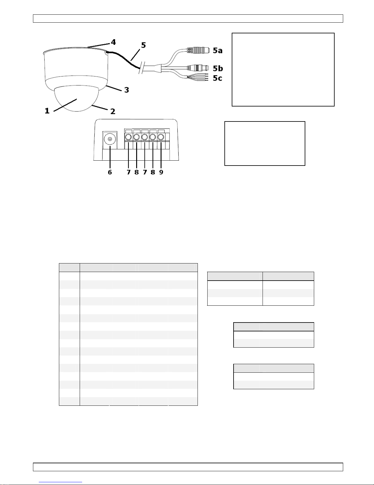
Camera
1. camera
2. transparante koepel
3. behuizing
4. montageplaat
5. aansluitkabel
5a. video-uitgang (BNC)
5b. voedingsingang
5c. communicatie
IR-ontvanger
6. ingang DC-voeding
7. RS-485 D+
8. RS-485 D-
9. massa
Page 10

CAMCOLD7
00 (17/09/2008)
10
7.
Installatie
•
Verwijder de montageplaat (4) van de behuizing (3) door de plaat naar rechts te draaien.
•
Bevestig de montageplaat (4) aan het plafond met behulp van de 4 schroeven.
•
Bevestig de camera aan de montageplaat (4): plaats de pinnen op de montageplaat (4)
in de groeven van de behuizing en draai de camera naar rechts.
•
Sluit de video-uitgang (5a) aan de monitor/DVR/multiplexer/…
•
Sluit de communicatiekabel (5c) aan de IR-ontvanger (7, 8 en 9):
Gele draad Alarmingang Groene draad RS-485 D+
Blauwe draad Massa Rode draad RS-485 D-
•
Maak een aansluiting met de IR-ontvanger en/of een bestaande anti-sabotageschakelaar
(niet meegeleverd), bewegingssensor (niet meegeleverd), alarmsysteem (niet
meegeleverd), enz. met de blauwe en gele draad.
•
Sluit de voeding aan de voedingsingang (5b) van de camera.
•
Sluit een voeding van 12 VDC / 1 A (bv. onze PS1210 – niet meegeleverd) aan de DCingang (6) van de IR-ontvanger.
8.
Gebruik
•
Na het aansluiten van de voeding draait de camera naar de standaardpositie en schakelt
hij in stand-by.
•
Druk op [0] > [ENTER] zodat de controller alle aangesloten camera’s erkent. De
ontvanger piept kort. Lukt dit niet, dan zal de ontvanger eenmaal lang en driemaal kort
piepen.
Opmerking: De afstandsbediening kan enkel de laagste 9 adressen besturen.
•
Selecteer de camera die u wenst te besturen met behulp van de cijfertoetsen ([1] ~ [9])
op de afstandsbediening en druk daarna op [ENTER].
Opmerking: Er bestaat geen verband tussen de ingedrukte cijfertoets en het adres van de
camera. De camera met het laagste adres wordt automatisch toegewezen naar
cijfertoets [1], enz.
•
Verplaats de camera met / / / . Merk op dat de draaisnelheid niet verandert.
•
De camera heeft een geheugen tot 16 presets die u met een enkele druk op een toets
kunt opvragen.
•
Hoe een preset instellen: selecteer de camera en plaats hem op de gewenste positie met
/ / / op de afstandsbediening. Druk op een cijfertoets en daarna op [SET PRESET]
om deze positie te bewaren. Stel zo alle gewenste presets in. Let op: Een bestaande
preset wordt overschreven indien u tweemaal dezelfde cijfertoets indrukt.
•
Vraag een preset op door eerst de camera te selecteren en daarna de gewenste preset te
selecteren en op [GO PRESET] te drukken.
•
De camera is uitgerust met een auto panfunctie. Afhankelijk van de geselecteerde optie
scant de camera automatisch 4, 8 op 16 presets:
[1] snelle pan, 4 presets [4] trage pan, 8 presets
[2] trage pan, 4 presets [5] snelle pan, 16 presets
[3] snelle pan, 8 presets [6] trage pan, 16 presets
•
Start de auto panfunctie door op een cijfertoets ([1] ~ [6]) en daarna op [AUTO PAN] te
drukken. Druk opnieuw op [AUTO PAN] of op een pijltjestoets om de functie te stoppen.
Opmerking: Aangezien de afstandsbediening van het universele type is, zijn de functies
[AUTOFOCUS] [ZOOM IN] [ZOOM OUT] [FOCUS NEAR] [FOCUS FAR] [SPEED +]
[SPEED -] niet beschikbaar.
•
Bij alarm (gele draad) wordt de zoemer van de IR-ontvanger ingeschakeld. Schakel de
zoemer uit door op [EVENT RST] te drukken: de controller schakelt automatisch over naar
de camera die het alarm inschakelde.
Page 11

CAMCOLD7
00 (17/09/2008)
11
9.
Omschrijving afstandsbediening
Functie Afstandsbediening
Zoek aansluiting [0] -> [ENTER]
Draai/omhoog
Druk op [ ]
Draai/omlaag
Druk op [ ]
Draai/links
Druk op [ ]
Gebruik van de camera
Draai/rechts
Druk op [ ]
Selecteer camera Cijfertoets ([1] ~ [9]) -> [ENTER]
Stel preset in Cijfertoets (16 presets) -> [SET PRESET]
Vraag preset op Cijfertoets (16 presets) -> [GO PRESET]
Start preset auto pan op ([1] ~ [6]) -> [AUTO PAN]
Stop preset auto pan
[AUTO PAN] of [
/ / /
]
Schakel alarm uit [EVENT RESET]
Geen functie
[AUTOFOCUS] [ZOOM IN] [ZOOM OUT] [FOCUS NEAR] [FOCUS
FAR] [SPEED +] [SPEED -]
10.
Problemen en oplossingen
De camera functioneert niet
Controleer de voeding en gebruik de correcte
voedingsadapter.
Geen beeld op de monitor Controleer de aansluiting van de BNC video-uitgang.
Kan de camera niet besturen
Controleer de ID-instelling.
Controleer de RS-485 communicatielijnen.
Controleer of er inderdaad een alarmsituatie aanwezig is.
Herstart de camera.
11.
Technische specificaties
camera
systeem PAL
sensor 1/3" Sony Super HAD kleuren-CCD
aantal pixels 582 (H) x 500 (V)
horizontale resolutie 380 tv-lijnen
S/R-verhouding video ≥ 48 dB
min. verlichting 0,2 lux / F2,0
iris automatisch
focuslengte 3,6 mm
tegenlichtcompensatie ja
uitgangsniveau video 1,0 Vpp / 75 Ω, composiet
synchronisatiesysteem intern (negatieve synchronisatie)
gainregeling automatisch
witbalans automatisch
elektronische sluiter automatisch (1/50 s-1/110 000 s)
pan/tilt
panhoek 0° - 340°
tilthoek 0° - 80°
manuele snelheidsregeling pan 1° - 150°
manuele snelheidsregeling tilt 1° - 100°
auto snelheidsregeling pan 1° - 300°
auto snelheidsregeling tilt 1° - 200°
presets 16 presets (6 groepen)
communicatie RS-485
Page 12

CAMCOLD7
00 (17/09/2008)
12
protocol Pelco-P of Pelco-D (instelbaar)
baudsnelheid 2400, 4800, 9600 bits/s (instelbaar)
behuizing gegoten ABS
alarm 1 ingang
algemeen
voeding 12 VDC / 1 A (PS1210 niet meegelev.)
afmetingen Ø 143 x 135 mm
gewicht 750 g
opties
bedieningspaneel via RS-485
CAMCOLD/CK, VWS2E, DVR4MQAEE, DVR4MQAE, DVR8N2,
DVR16N
Gebruik dit toestel enkel met originele accessoires. Velleman nv is niet
aansprakelijk voor schade of kwetsuren bij (verkeerd) gebruik van dit toestel.
Voor meer informatie over dit product, zie www.velleman.eu. De informatie in
deze handleiding kan te allen tijde worden gewijzigd zonder voorafgaande
kennisgeving.
Page 13
CAMCOLD7
00 (17/09/2008)
13
NOTICE D’EMPLOI
1.
Introduction
Aux résidents de l'Union européenne
Des informations environnementales importantes concernant ce produit
Ce symbole sur l'appareil ou l'emballage indique que l’élimination d’un appareil en
fin de vie peut polluer l'environnement. Ne pas jeter un appareil électrique ou
électronique (et des piles éventuelles) parmi les déchets municipaux non sujets au
tri sélectif ; une déchèterie traitera l’appareil en question. Renvoyer les
équipements usagés à votre fournisseur ou à un service de recyclage local. Il convient de
respecter la réglementation locale relative à la protection de l’environnement.
En cas de questions, contacter les autorités locales pour élimination.
Nous vous remercions de votre achat ! Lire la présente notice attentivement avant la mise
en service de l’appareil. Si l’appareil a été endommagé pendant le transport, ne pas
l’installer et consulter votre revendeur.
2.
Prescriptions de sécurité
Garder le thermomètre hors de la portée de personnes non qualifiées et
de jeunes enfants.
UNIQUEMENT POUR USAGE À L’INTÉRIEUR. Protéger l’appareil contre la
pluie, l’humidité et les éclaboussures.
Risque d’électrochocs lors de l’ouverture du boîtier.
Il n’y a aucune pièce maintenable par l’utilisateur. Commander des pièces de
rechange éventuelles chez votre revendeur.
• La garantie ne s’applique pas aux dommages survenus en négligeant certaines directives
de cette notice et votre revendeur déclinera toute responsabilité pour les problèmes et les
défauts qui en résultent.
• Les dommages occasionnés par des modifications à l’appareil par le client ne tombent pas
sous la garantie.
3.
Directives générales
• Protéger la caméra contre les chocs et la traiter avec circonspection pendant l’installation
et l’opération.
• Tenir le thermomètre à l’écart de la poussière, l’humidité et des températures extrêmes.
• Se familiariser avec le fonctionnement de l’appareil avant de l’utiliser.
• Toute modification de l’appareil est interdite pour des raisons de sécurité.
• N’utiliser le thermomètre qu’à sa fonction prévue. Un usage impropre annule d'office la
garantie.
4.
Caractéristiques
• caméra aux dimensions multi-applications
• fonction de menu à l’écran OSD
• commande à distance depuis interface RS-485 Pelco-P et Pelco-D
• possibilité de pilotage jusqu’à 15 appareils en utilisant le kit de contrôle IR
• fonction de balayage automatique
• uniquement pour usage à l’intérieur
Page 14

CAMCOLD7
00 (17/09/2008)
14
5.
Description
6.
Paramétrage
•
Avant d’installer la caméra, il est nécessaire de la paramétrer à l’aide des interrupteurs
DIP à l’intérieur du boîtier. Ouvrir le boîtier en desserrant le dôme (2).
•
Procéder avec précaution et s’assurer de ne pas endommager les composantes internes.
•
Paramétrer l’adresse de la caméra avec les interrupteurs SW1 ~ SW4 (jusqu’à 15
adresses). Cependant, l’utilisation de la télécommande ne vous permettra de piloter que
les 9 premières adresses.
•
Paramétrer la vitesse de transmission avec les interrupteurs DIP SW5 et SW6,
sélectionner le protocole avec l’interrupteur SW7 et le contact d’alarme (normalement
ouvert (N.O.) ou fermé (N.F.)) avec l’interrupteur SW8.
ID SW1 SW2 SW3 SW4
0 OFF OFF OFF OFF SW5 SW6 BAUD
1 ON OFF OFF OFF ON ON 2400
2 OFF ON OFF OFF OFF ON 4800
3 ON ON OFF OFF ON OFF 9600
4 OFF OFF ON OFF
5 ON OFF ON OFF
6 OFF ON ON OFF SW7 Protocole
7 ON ON ON OFF ON Standard
8 OFF OFF OFF ON
OFF PELCO
9 ON OFF OFF ON
10 OFF ON OFF ON
11 ON ON OFF ON SW8
Type d’alarme
12 OFF OFF ON ON ON N.O.
13 ON OFF ON ON
OFF N.C.
14 OFF ON ON ON
15 ON ON ON ON
•
Refermer le boîtier en replaçant le dôme (2) et en le serrant vers la gauche. Fixer avec la
petite vis.
Caméra dôme
1. caméra
2. dôme transparent
3. boîtier
4. plaquette de montage
5. câble d’entrée/de sortie
5a. sortie vidéo (BNC)
5b. entrée d’alimentation
5c. communication
récepteur IR
6. entrée d’alimentation CC
7. RS-485 D+
8. RS-485 D-
9. masse
Page 15

CAMCOLD7
00 (17/09/2008)
15
7.
Installation
•
Retirer la plaquette de montage (4) du boîtier (3) en la tournant vers la droite.
•
Fixer la plaquette de montage (4) au plafond à l’aide de 4 vis.
•
Fixer la caméra à la plaquette (4) en alignant les broches aux trous dans le boîtier.
Tourner la caméra.
•
Raccorder la sortie vidéo (5a) à un moniteur/DVR/multiplexer/…
•
Raccorder le câble de communication (5c) au récepteur IR (7, 8 et 9):
Fil jaune Entrée d’alarme Fil vert RS-485 D+
Fil bleu Masse Fil rouge RS-485 D-
•
Utiliser les fils jaune et bleu pour établir la connexion entre le récepteur IR et/ou un
contact anti-sabotage (non incl.), un capteur de mouvement (non incl.), un système
d’alarme (non incl.), etc.
•
Mettre la caméra sous tension.
•
Raccorder une alimentation 12 VCC / 1 A (p.ex. PS1210 – non incluse) à l’entrée CC (6)
du récepteur.
8.
Emploi
•
Après la mise sous tension, la camera se positionnera en position standard et elle
commutera en mode veille.
•
Enfoncer [0] > [ENTER] pour établir la connexion entre le contrôleur et la (les)
caméra(s). Le récepteur émet une tonalité. Une longue tonalité suivie par 3 courtes
tonalités signifie que la connexion n’a pas été établie.
Remarque : L’utilisation de la télécommande ne vous permettra de piloter que les 9
premières adresses.
•
Sélectionner la caméra en enfonçant la touche numérique ([1]~ [9]) correspondante sur
la télécommande. Enfoncer [ENTER].
Remarque : Il n’y a pas de rapport direct entre la saisie et l’adresse de la camera. La
caméra ayant l’adresse la moins élevée sera assignée sous la touche [1], etc.
•
Déplacer la caméra en enfonçant la touche [ / / / ] sur lé télécommande. Remarque :
la vitesse de rotation est invariable.
•
Il est possible de mémoriser jusqu’à 16 présélections. Ces présélections peuvent être
appelées à l’aide d’une seule touche.
•
Paramétrage d’une présélection : sélectionner la caméra et la déplacer vers le point
souhaité à l’aide de la touche [ / / / ].Enfoncer une touche numérique sur la
télécommande et ensuite confirmer avec la touche [SET PRESET]. Procéder de façon
semblable pour paramétrer le reste des présélections. Attention : une deuxième pression
sur une même touche écrasera la présélection mémorisée.
•
Appeler la présélection en enfonçant la touche numérique et la touche [GO PRESET].
•
La caméra est équipée d’une fonction pan automatique. La caméra balayera 4, 8 ou 16
présélections selon l’option sélectionnée.
[1] pan rapide, 4 présélections [4] pan lent, 8 présélections
[2] pan lent, 4 présélections [5] pan rapide, 16 présélections
[3] pan rapide, 8 présélections [6] pan lent, 16 présélections
•
Démarrer la fonction en sélectionnant une option ([1] ~ [6]) et en confirmant avec la
touché [AUTO PAN].
•
Arrêter la fonction en enfonçant la touche [AUTO PAN] ou la touche [ / / / ] sur lé
télécommande.
Remarque : La télécommande étant de type universelle, les fonctions suivantes ne sont pas
disponibles : [AUTOFOCUS] [ZOOM IN] [ZOOM OUT] [FOCUS NEAR] [FOCUS FAR]
[SPEED +] [SPEED -].
•
En cas d’alarme (fil jaune), le ronfleur du récepteur IR est activé. Enfoncer la touche
[EVENT RST] sur la télécommande pour le désactiver. Le contrôleur commute
automatiquement vers la caméra ayant déclenchée l’alarme.
Page 16

CAMCOLD7
00 (17/09/2008)
16
9.
Description de la télécommande
Fonction Télécommande
Connexion [0] -> [ENTER]
Rotation/haut
Enfoncer [ ]
Rotation/bas
Enfoncer [ ]
Rotation/gauche
Enfoncer [ ]
Commande de la caméra
Rotation/droite
Enfoncer [ ]
Sélection de la caméra Touche ([1] ~ [9]) -> [ENTER]
Paramétrage présélection Touche numérique (16 présélections) -> [SET PRESET]
Présélection Touche numérique (16 présélections) -> [GO PRESET]
Activation pan automatique ([1] ~ [6]) -> [AUTO PAN]
Désactivation pan automatique
[AUTO PAN] ou [
/ / /
]
Désactivation de l’alarme [EVENT RESET]
Pas de fonction
[AUTOFOCUS] [ZOOM IN] [ZOOM OUT] [FOCUS NEAR] [FOCUS
FAR] [SPEED +] [SPEED -]
10.
Problèmes et solutions
La caméra ne fonctionne pas Vérifier le type d’adaptateur secteur.
Pas d’image Vérifier la connexion de la sortie vidéo BNC.
Caméra incontrôlable
Vérifier l’adresse.
Vérifier la communication RS-485.
S’assurer d’une situation d’alarme.
Réinitialiser la caméra.
11. Spécifications techniques
caméra
système PAL
capteur CCD 1/3" Sony Super HAD couleur
pixels 582 (H) x 500 (V)
résolution horizontale 380 lignes TV
rapport S/B vidéo ≥ 48 dB
éclairement min. 0,2 lux / F2,0
iris auto
longueur focale 3,6 mm
compensation de contre-jour oui
niveau de sortie vidéo 1,0 Vpp / 75 Ω, composite
système de synchronisation interne (synchronisation négative)
réglage du gain auto
balance des blancs auto
obturateur électronique auto (1/50 s-1/110 000 s)
pan/tilt
angle pan 0° - 340°
angle tilt 0° - 80°
vitesse pan manuelle 1° - 150°
vitesse tilt manuelle 1° - 100°
vitesse pan auto 1° - 300°
vitesse tilt auto 1° - 200°
présélections 16 présélections (6 groupes)
communication RS-485
protocole Pelco-P ou Pelco-D (sélectionnable)
Page 17

CAMCOLD7
00 (17/09/2008)
17
vitesse de transmission 2400, 4800, 9600 bits/s (sélectionnable)
boîtier plastique ABS moulé
alarme 1 entrée
général
alimentation 12 VCC / 1 A (PS1210 non incl.)
dimensions Ø 143 x 135 mm
poids 750 g
options
panneau de commande depuis
RS-485
CAMCOLD/CK, VWS2E, DVR4MQAEE, DVR4MQAE, DVR8N2,
DVR16N
N’employer cet appareil qu’avec des accessoires d’origine. SA Velleman ne sera
aucunement responsable de dommages ou lésions survenus à un usage (incorrect)
de cet appareil. Pour plus d’information concernant cet article, visitez notre site
web www.velleman.eu. Toutes les informations présentées dans cette notice
peuvent être modifiées sans notification préalable.
Page 18

CAMCOLD7
00 (17/09/2008)
18
MANUAL DEL USUARIO
1.
Introducción
A los ciudadanos de la Unión Europea
Importantes informaciones sobre el medio ambiente concerniente a este producto
Este símbolo en este aparato o el embalaje indica que, si tira las muestras
inservibles, podrían dañar el medio ambiente. No tire este aparato (ni las pilas, si las
hubiera) en la basura doméstica; debe ir a una empresa especializada en reciclaje.
Devuelva este aparato a su distribuidor o a la unidad de reciclaje local.
Respete las leyes locales en relación con el medio ambiente.
Si tiene dudas, contacte con las autoridades locales para residuos.
¡Gracias por haber comprado la CAMCOLD7! Lea atentamente las instrucciones del manual
antes de usarla. Si el aparato ha sufrido algún daño en el transporte no lo instale y póngase
en contacto con su distribuidor.
2.
Instrucciones de seguridad
Mantenga el aparato lejos del alcance de personas no capacitadas y
niños.
SÓLO PARA EL USO EN INTERIORES. No exponga este equipo a lluvia,
humedad ni a ningún tipo de salpicadura o goteo.
Riesgo de descargas eléctricas al abrir la caja.
El usuario no habrá de efectuar el mantenimiento de ninguna pieza. Contacte con
su distribuidor si necesita piezas de recambio.
• Daños causados por descuido de las instrucciones de seguridad de este manual
invalidarán su garantía y su distribuidor no será responsable de ningún daño u otros
problemas resultantes.
• Los daños causados por modificaciones no autorizadas, no están cubiertos por la garantía.
3.
Normas generales
• No agite el aparato. Evite usar excesiva fuerza durante el manejo y la instalación.
• No exponga este aparato a polvo, humedad y temperaturas extremas.
• Familiarícese con el funcionamiento del aparato antes de utilizarlo.
• Por razones de seguridad, las modificaciones no autorizadas del aparato están prohibidas.
• Utilice sólo el aparato para las aplicaciones descritas en este manual. Un uso
desautorizado anula la garantía completamente.
4.
Características
• diseño elegante y adecuada para diferentes aplicaciones
• función OSD (On-Screen Display)
• mando a distancia por interfaz RS-485 Pelco-P y Pelco-D
• es posible controlar hasta 15 aparatos con el controlador IR inalámbrico
• función de exploración automática
• sólo para uso en interiores
Page 19

CAMCOLD7
00 (17/09/2008)
19
5.
Descripción
6.
Ajuste
•
Antes de instalar la cámara, es necesario ajustarla con los interruptores DIP del interior
de la caja. Abra la caja al desatornillar la cúpula (2).
•
Sea cuidadoso y asegúrese de que no dañe los componentes internos.
•
Ajuste la dirección ID de la cámara con los interruptores SW1 ~ SW4 (hasta 15
direcciones). Si utiliza el mando a distancia sólo es posible controlar las 9 primeras
direcciones.
•
Ajuste la velocidad de transmisión con los interruptores DIP SW5 y SW6. Seleccione el
protocolo con el interruptor SW7 y el contacto de alarma (normalmente abierto (N.A.) o
cerrado (N.C.) con el interruptor SW8.
ID SW1 SW2 SW3 SW4
0 OFF OFF OFF OFF SW5 SW6 BAUD
1 ON OFF OFF OFF ON ON 2400
2 OFF ON OFF OFF OFF ON 4800
3 ON ON OFF OFF ON OFF 9600
4 OFF OFF ON OFF
5 ON OFF ON OFF
6 OFF ON ON OFF SW7 Protocole
7 ON ON ON OFF ON Estándar
8 OFF OFF OFF ON
OFF PELCO
9 ON OFF OFF ON
10 OFF ON OFF ON
11 ON ON OFF ON SW8
Tipo de
alarma
12 OFF OFF ON ON ON N.A.
13 ON OFF ON ON
OFF N.C.
14 OFF ON ON ON
15 ON ON ON ON
•
Cierre la caja al volver a poner la cúpula (2) y al girarlo hacia la izquierda. Fije con el
pequeño tornillo.
Cámara domo
1. cámara
2. cúpula transparente
3. caja
4. placa de montaje
5. cable de entrada/salida
5a. salida de vídeo (BNC)
5b. entrada de alimentación
5c. comunicación
Receptor IR
6. entrada de alimentación
CC
7. RS-485 D+
8. RS-485 D-
9. masa
Page 20

CAMCOLD7
00 (17/09/2008)
20
7.
Instalación
•
Saque la placa de montaje (4) de la caja (3) al girarla hacia la derecha.
•
Fije la placa de montaje (4) con los 4 tornillos al techo.
•
Fije la cámara a la placa (4) al alinear los polos con los agujeros de la caja. Gire la
cámara.
•
Conecte la salida de vídeo (5a) a un monitor/DVR/multiplexer/…
•
Conecte el cable de comunicación (5c) al receptor IR (7, 8 y 9):
Hilo amarillo Entrada de
alarma
Hilo verde RS-485 D+
Hilo azul Masa Hilo rojo RS-485 D-
•
Utilice el hilo amarillo y el hilo azul para establecer la conexión entre el receptor IR y/o un
contacto antisabotaje (no incl.), un sensor de movimiento (no incl.), un sistema de
alarma (no incl.), etc.
•
Ponga la cámara bajo tensión.
•
Conecte una alimentación de 12 VCC / 1 A (p.ej. PS1210 – no incl.) a la entrada CC (6)
del receptor.
8.
Uso
•
Después de la puesto bajo tensión, la cámara se pone en la posición estándar y conmuta
al modo de espera (stand-by).
•
Pulse [0] > [ENTER] para establecer la conexión entre el controlador y la (las) cámara(s).
El receptor emite un sonido. Un sonido largo seguido por 3 sonidos cortos significa que no
se ha realizado la conexión.
Nota: Si utiliza el mando a distancia sólo es posible controlar las 9 primeras direcciones.
•
Seleccione la cámara al pulsar la tecla numérica ([1]~ [9]) correspondiente del mando a
distancia. Pulse [ENTER].
Nota: no hay ninguna relación directa entre la tecla numérica pulsada y la dirección de la
cámara. La cámara con la dirección más baja se atribuirá a la tecla numérica [1], etc.
•
Desplace la cámara al pulsar la tecla [ / / / ] del mando a distancia. Tenga en cuenta
que la velocidad de rotación no cambia.
•
Es posible guardar hasta 16 preselecciones que pueden ser recordadas con una sola tecla.
•
Ajustar una preselección: seleccione la cámara y póngala con la tecla [ / / / ] en el
punto deseado. Pulse una tecla del mando a distancia y luego confirme con la tecla [SET
PRESET]. Continúe de la misma manera para ajustar las otras preselecciones. ¡Ojo!: Se
sobre-escribirá la preselección guardada al pulsar la misma tecla numérica una segunda
vez.
•
Recuerde la preselección al pulsar la tecla numérica y la tecla [GO PRESET].
•
La cámara está equipada con una función pan automático. La cámara explorará 4, 8 ó 16
preselecciones según la opción seleccionada.
[1]
pan rápido, 4
preselecciones
[4] pan lento, 8 preselecciones
[2] pan lento, 4 preselecciones [5]
pan rápido, 16
preselecciones
[3]
pan rápido, 8
preselecciones
[6] pan lento, 16 preselecciones
•
Active la función al seleccionar una opción ([1] ~ [6]) y al confirmar con la tecla [AUTO
PAN].
•
Desactive la función al pulsar la tecla [AUTO PAN] o la tecla [ / / / ] del mando a
distancia.
Nota
: Visto que el mando a distancia está del tipo universal, las siguientes funciones no
están: [AUTOFOCUS] [ZOOM IN] [ZOOM OUT] [FOCUS NEAR] [FOCUS FAR] [SPEED
+] [SPEED -].
•
En caso de alarma (hilo amarillo), se activa el zumbador del receptor IR. Pulse la tecla
[EVENT RST] del mando a distancia para desactivarlo. El controlador conmuta
automáticamente a la cámara que ha activado la alarma.
Page 21

CAMCOLD7
00 (17/09/2008)
21
9.
Descripción del mando a distancia
Función Mando a distancia
Conexión [0] -> [ENTER]
Rotación/arriba
Pulse [ ]
Rotación /abajo
Pulse [ ]
Rotación /izquierda
Pulse [ ]
Control de la cámara
Rotación /derecha
Pulse [ ]
Selección de la cámara Tecla ([1] ~ [9]) -> [ENTER]
Ajuste preselección Tecla numérica (16 preselecciones) -> [SET PRESET]
Preselección Tecla numérica (16 preselecciones) -> [GO PRESET]
Activación pan automática ([1] ~ [6]) -> [AUTO PAN]
Desactivación pan automática
[AUTO PAN] o [
/ / /
]
Desactivación de la alarma [EVENT RESET]
Sin función
[AUTOFOCUS] [ZOOM IN] [ZOOM OUT] [FOCUS NEAR] [FOCUS
FAR] [SPEED +] [SPEED -]
10.
Solución de problemas
La cámara no funciona
Controle la alimentación y utilice el adaptador de red
adecuado.
No hay una imagen Controle la conexión de la salida de vídeo BNC.
Cámara incontrolable
Controle la dirección.
Controle la comunicación RS-485.
Controle si hay una situación de alarma.
Reinicialice la cámara.
11. Especificaciones
cámara
sistema PAL
sensor Sony Super HAD color CCD de 1/3"
píxeles 582 (H) x 500 (V)
resolución horizontal 380 líneas TV
relación señal / ruido vídeo ≥ 48 dB
iluminación mínima 0,2 lux / F2,0
iris auto
longitud foco 3,6 mm
compensación de contraluz
(BLC)
sí
nivel de salida de vídeo 1,0 Vpp / 75 Ω, compuesto
sincronización interna (sincronización negativa)
control de ganancia automático
balance de blancos automático
control shutter electrónico automático (1/50 s-1/110 000 s)
pan/tilt
ángulo pan 0° - 340°
ángulo tilt 0° - 80°
velocidad pan manual 1° - 150°
velocidad tilt manual 1° - 100°
velocidad pan automática 1° - 300°
velocidad tilt automática 1° - 200°
preselecciones 16 preselecciones (6 grupos)
Page 22

CAMCOLD7
00 (17/09/2008)
22
comunicación RS-485
protocolo Pelco-P o Pelco-D (seleccionable)
velocidad de transmisión 2400, 4800, 9600 bits/s (seleccionable)
caja ABS, carcasa de plástico, fundición a presión
alarma 1 entrada
general
alimentación 12 VCC / 1 A (PS1210 no incl.)
dimensiones Ø 143 x 135 mm
peso 750 g
opciones
panel de control por RS-485
CAMCOLD/CK, VWS2E, DVR4MQAEE, DVR4MQAE, DVR8N2,
DVR16N
Utilice este aparato sólo con los accesorios originales. Velleman Spain SL no será
responsable de daños ni lesiones causados por un uso (indebido) de este aparato.
Para más información sobre este producto, visite nuestra página web
www.velleman.eu. Se pueden modificar las especificaciones y el contenido de este
manual sin previo aviso.
Page 23

CAMCOLD7
00 (17/09/2008)
23
BEDIENUNGSANLEITUNG
1.
Einführung
An alle Einwohner der Europäischen Union
Wichtige Umweltinformationen über dieses Produkt
Dieses Symbol auf dem Produkt oder der Verpackung zeigt an, dass die Entsorgung
dieses Produktes nach seinem Lebenszyklus der Umwelt Schaden zufügen kann.
Entsorgen Sie die Einheit (oder verwendeten Batterien) nicht als unsortiertes
Hausmüll; die Einheit oder verwendeten Batterien müssen von einer spezialisierten
Firma zwecks Recycling entsorgt werden. Diese Einheit muss an den Händler oder
ein örtliches Recycling-Unternehmen retourniert werden. Respektieren Sie die örtlichen
Umweltvorschriften.
Falls Zweifel bestehen, wenden Sie sich für Entsorgungsrichtlinien an Ihre örtliche
Behörde.
Wir bedanken uns für den Kauf der CAMCOLD7! Lesen Sie diese Bedienungsanleitung vor
Inbetriebnahme sorgfältig durch. Überprüfen Sie, ob Transportschäden vorliegen. Sollte dies
der Fall sein, verwenden Sie das Gerät nicht und wenden Sie sich an Ihren Händler.
2.
Sicherheitshinweise
Halten Sie Kinder und Unbefugte vom Gerät fern.
NUR FÜR DIE ANWENDUNG IM INNENBEREICH. Schützen Sie das Gerät vor
Regen und Feuchte. Setzen Sie das Gerät keiner Flüssigkeit wie z.B. Tropf- oder
Spritzwasser, aus.
Stromschlaggefahr wenn Sie das Gehäuse öffnen.
Es gibt keine zu wartenden Teile. Bestellen Sie eventuelle Ersatzteile bei Ihrem
Fachhändler.
• Bei Schäden, die durch Nichtbeachtung der Bedienungsanleitung verursacht werden,
erlischt der Garantieanspruch. Für daraus resultierende Folgeschäden übernimmt der
Hersteller keine Haftung.
• Bei Schäden verursacht durch eigenmächtige Änderungen erlischt der Garantieanspruch.
3.
Allgemeine Richtlinien
• Vermeiden Sie Erschütterungen. Vermeiden Sie rohe Gewalt während der Installation und
Bedienung des Gerätes.
• Schützen Sie das Gerät vor extreme Temperaturen, Staub und Feuchte.
• Nehmen Sie das Gerät erst in Betrieb, nachdem Sie sich mit seinen Funktionen vertraut
gemacht haben.
• Eigenmächtige Veränderungen sind aus Sicherheitsgründen verboten.
• Verwenden Sie das Gerät nur für Anwendungen beschrieben in dieser
Bedienungsanleitung sonst kann dies zu Schäden am Produkt führen und erlischt der
Garantieanspruch.
4.
Eigenschaften
• elegantes Design und geeignet für verschiedene Applikationen
• OSD-Funktion (On-Screen Display)
• Fernbedienung über RS-485 Pelco-P und Pelco-D-Schnittstelle
• es können bis zu 15 Geräte über drahtlosen IR-Steuergerät gesteuert werden
Page 24

CAMCOLD7
00 (17/09/2008)
24
• automatische Scanfunktion
• eignet sich nur für die Anwendung im Innenbereich
5.
Umschreibung
6.
Konfiguration
•
Konfigurieren Sie die Kamera zuerst über die DIP-Schalter ehe Sie diese installieren. Die
DIP-Schalter befinden sich innerhalb der Kamera. Öffnen Sie die Kamera, indem Sie die
transparente Kuppel (2) nach rechts drehen.
•
Seien Sie vorsichtig und beachten Sie, dass Sie keine Komponenten innerhalb der Kamera
beschädigen wenn Sie die Schalter einstellen.
•
Stellen Sie die ID-Adresse der Kamera über SW1 ~ SW4 (15 mögliche Adressen) ein.
Wenn Sie die IR-Fernbedienung verwenden, können Sie nur die ersten 9 (niedrigsten)
Adressen kontrollieren.
•
Stellen Sie die Baudrate über SW5 und SW6 ein. Stellen Sie das Protokoll über SW7 ein
und stellen Sie den Alarmkontakt (normal offen (N.O.) oder geschlossen (N.C.)) über
SW8 ein.
ID SW1 SW2 SW3 SW4
0 OFF OFF OFF OFF SW5 SW6 BAUD
1 ON OFF OFF OFF ON ON 2400
2 OFF ON OFF OFF OFF ON 4800
3 ON ON OFF OFF ON OFF 9600
4 OFF OFF ON OFF
5 ON OFF ON OFF
6 OFF ON ON OFF SW7 Protokoll
7 ON ON ON OFF ON Standard
8 OFF OFF OFF ON
OFF PELCO
9 ON OFF OFF ON
10 OFF ON OFF ON
11 ON ON OFF ON SW8 Alarmtyp
12 OFF OFF ON ON ON N.O.
13 ON OFF ON ON
OFF N.C.
14 OFF ON ON ON
15 ON ON ON ON
•
Stellen Sie die Kuppel (2) auf die Kamera und drehen Sie diese nach links. Befestigen Sie
mit der kleinen Schraube.
Kamera
1. Kamera
2. transparente Kuppel
3. Gehäuse
4. Montageplatte
5. Anschlusskabel
5a. Video-Ausgang (BNC)
5b. Netzeingang
5c. Kommunikation
IR-Empfänger
6. Eingang DCNetzeingang
7. RS-485 D+
8. RS-485 D-
9. Mase
Page 25

CAMCOLD7
00 (17/09/2008)
25
7.
Installation
•
Entfernen Sie die Montageplatte (4) vom Gehäuse (3), indem Sie die Montageplatte nach rechts drehen.
•
Befestigen Sie die Montageplatte (4) mit den 4 Schrauben an der Decke.
•
Befestigen Sie die Kamera an der Montageplatte (4): stellen Sie die Bolzen auf die Montageplatte
(4), stecken Sie diese in die Löcher des Gehäuses und drehen Sie die Kamera nach rechts.
•
Verbinden Sie den Video-Ausgang (5a) mit dem Monitor/DVR/Multiplexer/…
•
Verbinden Sie das Kommunikationskabel (5c) mit dem IR-Empfänger (7, 8 und 9):
Gelbes Kabel Alarmeingang Grünes Kabel RS-485 D+
Blaues Kabel Massa Rotes Kabel RS-485 D-
•
Stellen Sie eine Verbindung mit dem IR-Empfänger und/oder dem bestehenden
Sabotagekontakt (nicht mitgeliefert), Bewegungssensor (nicht mitgeliefert), Alarmsystem
(nicht mitgeliefert), usw. mit dem blauen und gelben Kabel her.
•
Verbinden Sie die Stromversorgung mit dem Netzeingang (5b) der Kamera.
•
Verbinden Sie ein 12 VDC/1A-Netzteil (z.B. PS1210 – nicht mitgeliefert) mit dem DCEingang (6) des IR-Empfängers.
8.
Anwendung
•
Nachdem Sie das Netzteil angeschlossen haben, geht die Kamera zur Standardposition
und schaltet auf den Standby-Modus um.
•
Drücken Sie [0] > [ENTER] damit der Controller alle angeschlossenen Kameras detektiert.
Der Empfänger piepst kurz. Wenn dies nicht gelingt, so piepst der de Empfänger ein Mal
lang und drei Mal kurz.
Bemerkung: Die Fernbedienung kann nur die niedrigsten 9 Adressen steuern.
•
Wählen Sie die Kamera, die Sie über die Nummerntasten ([1] ~ [9]) der Fernbedienung
steuern möchten, und drücken Sie danach [ENTER].
Bemerkung: Es gibt keinen Zusammenhang zwischen der gedrückten Nummerntaste und
der Adresse der Kamera. Die Kamera mit der niedrigsten Adresse wird automatisch
der Nummerntaste [1], usw. zugewiesen.
•
Ändern Sie die Position der Kamera mit / / / . Bemerken Sie, dass die
Drehgeschwindigkeit sich nicht ändert.
•
Die Kamera hat einen Speicher für 16 voreingestellte Positionen, die Sie mit nur einem
einzigen Tastendruck Sie abrufen.
•
Wie eine voreingestellte Position einstellen: wählen Sie die Kamera und stellen Sie diese
mit / / / der Fernbedienung auf der gewünschte Position. Drücken Sie eine
Nummerntaste und danach [SET POSITION] um diese Position zu speichern. Stellen Sie
so alle gewünschten Positionen ein. Achtung: Eine bestehende Position wird
überschrieben wenn Sie zwei Mal dieselbe Nummerntaste drücken.
•
Rufen Sie eine Position ab, indem Sie zuerst die Kamera und danach und danach de
gewünschte Position auswählen und indem Sie [GO POSITION] drücken.
•
Die Kamera verfügt über eine automatische Panfunktion. Je nach die gewählte Option
scannt die Kamera automatisch 4, 8 oder 16 voreingestellte Positionen:
[1]
schnelle
Schwenkbewegung (Pan),
4 Positionen
[4]
Langsame
Schwenkbewegung (Pan), 8
Positionen
[2]
Langsame
Schwenkbewegung (Pan),
4 Positionen
[5]
schnelle Schwenkbewegung
(Pan), 16 Positionen
[3]
schnelle
Schwenkbewegung (Pan),
8 Positionen
[6]
Langsame
Schwenkbewegung (Pan),
16 Positionen
•
Starten Sie die automatische Panfunktion, indem Sie eine Nummerntaste ([1] ~ [6]) und
danach [AUTO PAN] drücken. Drücken Sie [AUTO PAN] wieder oder drücken Sie die
Richtungstaste, um die Funktion zu stoppen.
Bemerkung: Da die Fernbedienung eine Universalfernbedienung ist, stehen nachfolgende
Funktionen nicht zur Verfügung: [AUTOFOCUS] [ZOOM IN] [ZOOM OUT] [FOCUS
NEAR] [FOCUS FAR] [SPEED +] [SPEED -].
Page 26

CAMCOLD7
00 (17/09/2008)
26
•
Bei Alarm (gelbes Kabel) wird der Summer des IR-Empfängers eingeschaltet. Schalten Sie
den Summer aus, indem Sie [EVENT RST] drücken: der Controller schaltet automatisch
auf die die Kamera, die den Alarm eingeschaltet hat, um.
9.
Umschreibung Fernbedienung
Funktion Fernbedienung
Verbindung suchen [0] -> [ENTER]
Drehen/oben
Drücken Sie [ ]
Drehen /unten
Drücken Sie [ ]
Drehen /links
Drücken Sie [ ]
Die Kamera verwenden
Drehen /rechts
Drücken Sie [ ]
Eine Kamera auswählen Nummerntaste ([1] ~ [9]) -> [ENTER]
Position einstellen Nummerntaste (16 Positionen) -> [SET POSITION]
Position abrufen Nummerntaste (16 Positionen) -> [GO POSITION]
Position automatische
Schwenkbewegung (Pan)
starten
([1] ~ [6]) -> [AUTO PAN]
Position automatische
Schwenkbewegung (Pan)
stoppen
[AUTO PAN] oder [
/ / /
]
Alarm ausschalten [EVENT RESET]
Ohne Funktion
[AUTOFOCUS] [ZOOM IN] [ZOOM OUT] [FOCUS NEAR] [FOCUS
FAR] [SPEED +] [SPEED -]
10.
Problemlösung
Die Kamera funktioniert nicht
Überprüfen Sie die Stromversorgung und verwenden Sie das
geeignete Netzteil.
Es gibt kein Bild auf dem Monitor Überprüfen Sie den Anschluss des BNC Video-Ausganges.
Kann die Kamera nicht steuern
Überprüfen Sie die ID-Einstellung.
Überprüfen Sie die RS-485 Kommunikationslinien.
Überprüfen Sie, ob es tatsächlich eine Alarmsituation gibt.
Starten Sie die Kamera erneut.
11.
Technische Daten
Kamera
System PAL
Sensor 1/3" Sony Super HAD kleuren-CCD
Pixelanzahl 582 (H) x 500 (V)
horizontale Auflösung 380 TV-Zeilen
Video Signal/Rauschabstand ≥ 48 dB
Mindestbeleuchtung 0,2 lux / F2,0
Blende automatisch
Brennweite 3,6 mm
Gegenlichtkompensation (BLC) ja
Video-Ausgangspegel 1,0 Vpp / 75 Ω, komposit
Synchronisation intern (negative Synchronisation)
Verstärkungsregelung automatisch
Weißabgleich automatisch
elektronische
Verschlusssteuerung
automatisch (1/50 s-1/110 000 s)
Page 27

CAMCOLD7
00 (17/09/2008)
27
Schwenk/Neige
Schwenkwinkel (Pan) 0° - 340°
Neigewinkel (Tilt) 0° - 80°
manuelle
Geschwindigkeitsregelung der
Schwenkbewegung
1° - 150°
manuelle
Geschwindigkeitsregelung der
Neigebewegung
1° - 100°
automatische
Geschwindigkeitsregelung der
Schwenkbewegung
1° - 300°
automatische
Geschwindigkeitsregelung der
Neigebewegung
1° - 200°
Voreingestellte Positionen 16 Positionen (6 Gruppen)
Kommunikation RS-485
Protokoll Pelco-P oder Pelco-D (einstellbar)
Baudrate 2400, 4800, 9600 bits/s (einstellbar)
Gehäuse ABS-Kunststoffgehäuse, gegossen
Alarm 1 Eingang
Allgemein
Stromversorgung 12 VDC / 1 A (PS1210 nicht mitgeliefert)
Abmessungen Ø 143 x 135 mm
Gewicht 750 g
Optionen
Bedienungskonsole über RS-485
CAMCOLD/CK, VWS2E, DVR4MQAEE, DVR4MQAE, DVR8N2,
DVR16N
Verwenden Sie dieses Gerät nur mit originellen Zubehörteilen. Velleman NV
übernimmt keine Haftung für Schaden oder Verletzungen bei (falscher)
Anwendung dieses Gerätes. Für mehr Informationen zu diesem Produkt, siehe
www.velleman.eu. Alle Änderungen ohne vorherige Ankündigung vorbehalten.
 Loading...