

Page 1

CAMCOLD5 - 1 - VELLEMAN
CAMCOLD5 – MINI P/T COLOUR DOME CAMERA
1. Introduction
To all residents of the European Union
Important environmental information about this product
This symbol on the device or the package indicates that disposal of the device after its lifecycle could harm
the environment.
Do not dispose of the unit (or batteries) as unsorted municipal waste; it should be taken to a specialised
company for recycling.
This device should be returned to your distributor or to a local recycling service.
Respect the local environmental rules.
If in doubt, contact your local waste disposal authorities.
Thank you for buying the CAMCOLD5! Please read the manual thoroughly before bringing this device into service. If
the device was damaged in transit, don't install or use it and contact your dealer.
2. Safety Instructions
• Damage caused by disregard of certain guidelines in this manual is not covered by the warranty and the dealer
will not accept responsibility for any ensuing defects or problems.
• A qualified technician should install and service this device.
• There are no user-serviceable parts.
• Note that damage caused by user modifications to the device is not covered by the warranty.
• Keep the device away from children and unauthorised users.
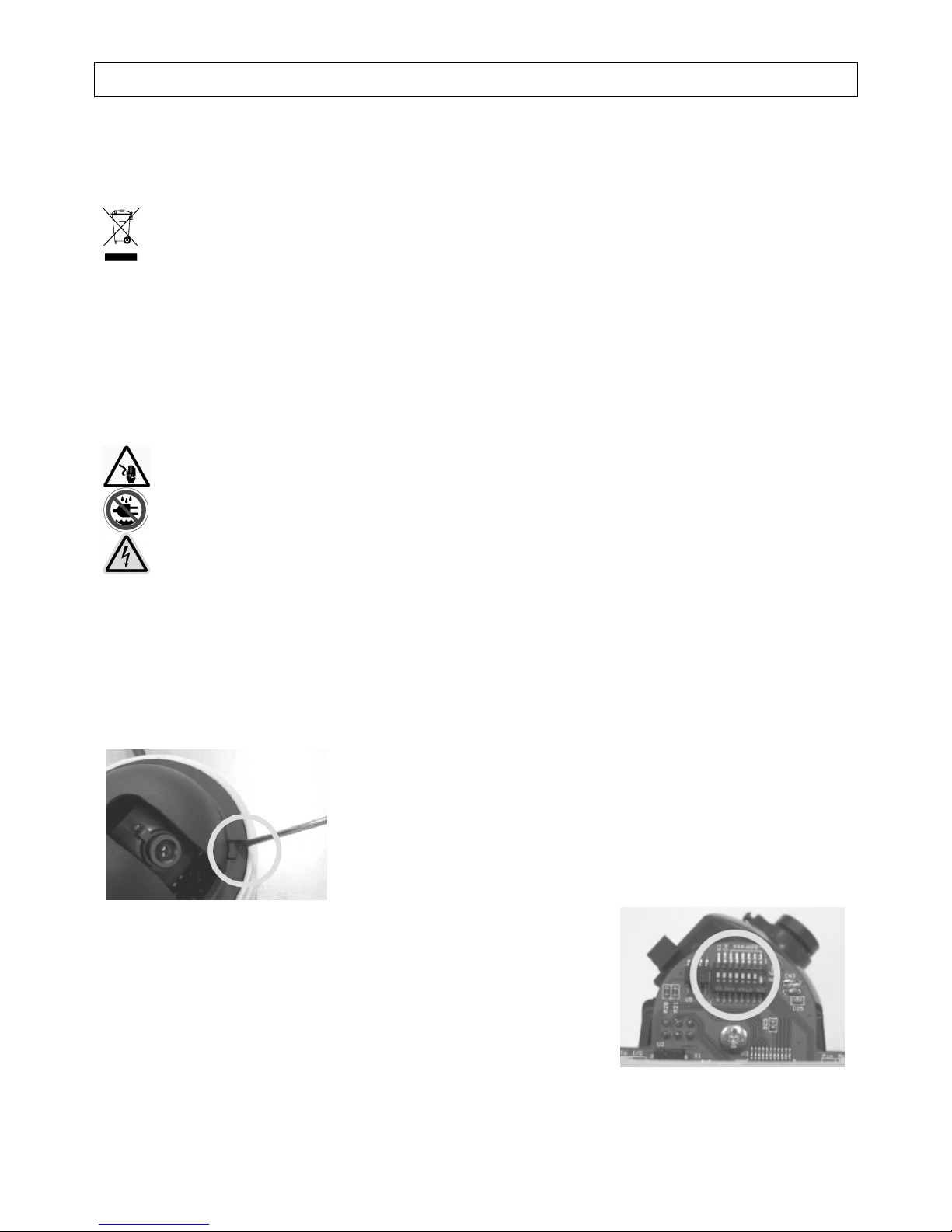
3. How to Set the DIP Switches
Press the tab on the side of the camera and remove the dome shield.
To configure your camera, adjust the DIP switches on the PCB. Refer to the
switch settings below.
Be very careful during the installation: touching live wires can cause life-threatening electroshocks.
Keep this device away from rain and moisture.
Presence of lethal voltage.
Page 2

CAMCOLD5 - 2 - VELLEMAN
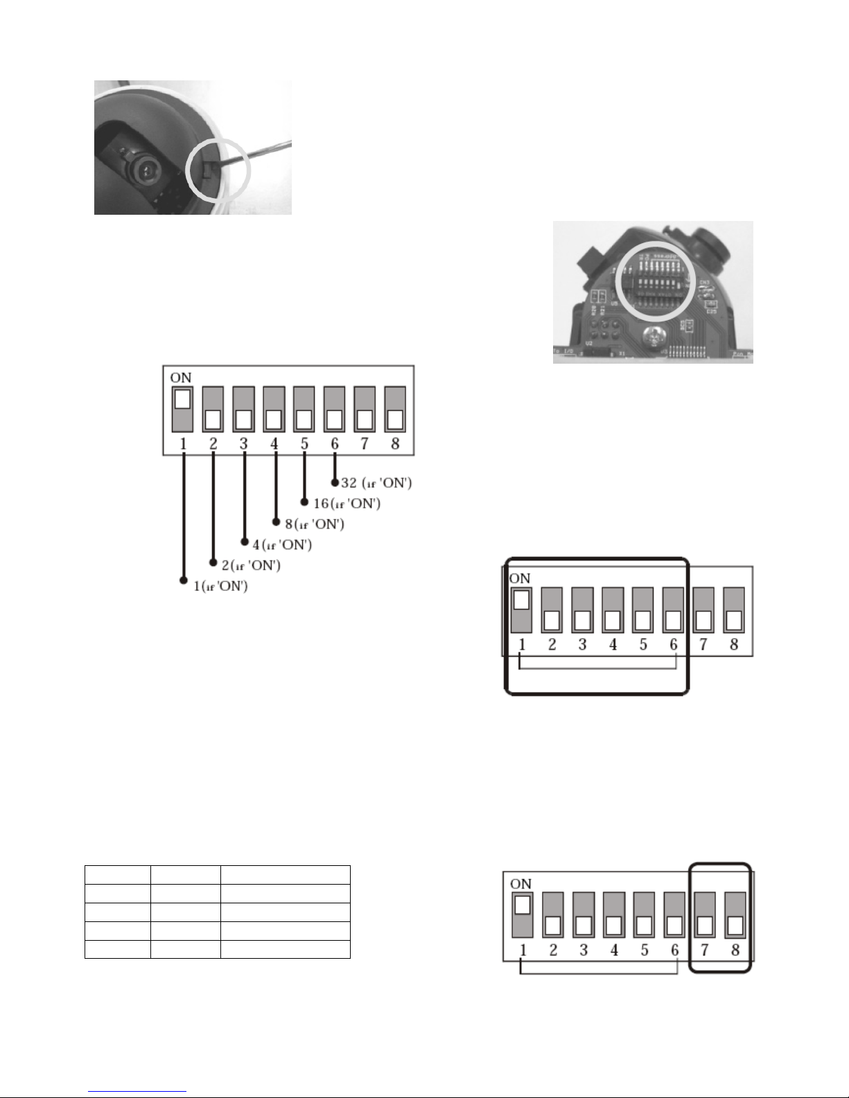
a. Camera ID Selection
• Set the binary number for the camera ID (1 ~ 63 except for 0) by
changing the DIP switch. Example: If you want to set the camera
ID as 10, switch on the following DIP switches: 0 + 2 + 0 + 8 + 0.
• The default camera ID is 1.
• When operating the camera with a controller, make sure the ID in
the DIP switch setting is identical to the camera ID of the
controller. If you operate several cameras, it is recommended to
memorize the camera ID as their respective location.
b. Control Protocol Selection
• Remove the power to the camera before changing the protocol.
• Select the appropriate protocol with the DIP switch combination.
Switch 7 Switch 8 Protocol / Baud rate
OFF OFF Pelco-D, 2400 bps
OFF ON Pelco-P, 4800 bps
ON OFF Pelco-D, 9600 bps
ON ON Pelco-P, 9600 bps
• If you want to control the camera using your DVR or P/T controller, make sure the protocol in those devices is
identical to the camera protocol. Otherwise, you will not be able to control the camera.
• Factory default protocol is Pelco-D, 2400 bps.
• Press F4 on the controller and select the same protocol as the one on the camera.
4. Mounting
a. Ceiling Mounting
1. Make a 30-40mm hole into the
ceiling using a hole saw.
2. Fix the mounting plate using the
included screws.
3. Insert the camera cable through
the hole.
Page 3

CAMCOLD5 - 3 - VELLEMAN
4. Locate the three transparent pins
on the camera and align them
with the three slots of the
mounting plate.
5. Fix the camera into the mounting
plate by pushing and twisting.
6. Now, mount the clear dome onto
the camera by turning it. Make
sure not to leave fingerprints on
the dome.
b. Wall Mounting
1. Remove the top cover
of the mounting
bracket.
2. Fix the mounting plate
on the mounting
bracket using the
included screws.
3. Mark the position of the
holes (68mm spacing)
of the mounting bracket
on the wall. Slightly
screw the screws into
the wall.
4. Now, slide the
mounting bracket over
the screws and make
the screws fit into the
slots of the bracket.
Tighten the screws.
5. Pass the cable through
the hole on the upper
side of the bracket.
6. Align the pins on the
camera with the slots
on the bracket. Push
and twist the camera so
it snaps into the
bracket.
7. Assemble the top cover
of the bracket and fix it
with the included
screws.
8. Now, mount the clear
dome onto the camera
by turning it. Make sure
not to leave fingerprints
on the dome.
5. Connection
Page 4

CAMCOLD5 - 4 - VELLEMAN
Power Connector
• Check the voltage and current capacity of the power source. The rated power to operate the CAMCOLD5 is
12VDC / 500mA.
• After connecting the power adapter wires to the included terminal block, plug into the power connector.
• Mind the polarity of the connector.
Video Out Connector
• Connect with a coaxial cable with BNC connector.
RS485 Connector
• After assembling the communication wires and the included 2-pin terminal, plug into the connector.
6. Remarks
• Check the power cable before powering the camera.
• The camera ID must be identical to that of the target camera. The camera ID can be checked by reading the DIP
switched of the camera.
• If your controller supports multiple protocols, the protocol must be changed to match that of the camera.
• After changing the camera protocol by modifying the DIP switches, the change will be effective after a camera
rebooting.
• Since the operation method can be different for each controller, refer to the manual of your controller if the
camera does not respond correctly.
7. Controlling the Dome Camera
a. Selecting the Camera
• Choose a camera by pressing the camera number 1 – 99 and the CAM key.
• Press -1 to choose the previous camera or press +1 to choose the next camera.
Example: Selecting camera n° 2.
o Press 2 and the CAM key to select camera n° 2.
o After having selected the camera, press -1 to select the previous camera or press +1 to select the next
camera.
b. Controlling the P/T and the Lens
• Select a camera (see “Selecting a Camera”).
• Press Z-, Z+, F- or F+ to control the P/T or tilt the joystick to control the lens.
Example: Controlling the P/T of camera n° 2.
o Press 2 and the CAM key to select camera n° 2.
o Tilt the joystick to control the camera P/T or use the Z-, Z+, F- or F+ key to control the lens.
c. Setting Up the Preset
• Select a camera and set the P/T and the lens to the desired position.
• Press the F1 key and press 8.
• Define the preset number (1 – 32).
• Press PRE to confirm.
Page 5

CAMCOLD5 - 5 - VELLEMAN
Example: Setting preset 15 to camera n° 5.
o Press 5 and then press the CAM key to select the camera.
o Move the P/T and the lens to the desired position.
o Press the F1 key.
o Press 8.
o Press 15.
o Press PRE to confirm your selection.
d. Running the Preset
• Select the desired camera number.
• Define the preset (1 - 32). The default preset is 1.
• Press the CALL key. The corresponding preset will be displayed on the screen.
Example: Setting camera n° 3 to preset 6.
o Press 3.
o Press the CAM key.
o Press 6.
o Press the CALL key.
o Preset 6 of camera n° will be displayed.
e. Pausing a Running Preset
• Select the desired camera ID (1 – 63).
• Press the HOLD key or tilt the joystick. The auto running preset will be paused.
Example: Pausing the preset of camera n° 4.
o Press 4.
o Press the CAM key.
o Press HOLD or tilt the joystick. The preset of camera 4 will be paused.
8. Troubleshooting
Problem Possible Cause Solution
Wrong connection. Check the connection. The camera does not react when
connected to a power supply.
Power deficiency. Check the power supply.
Wrong camera ID or baud rate. Reset the camera ID or baud rate.
Wrong protocol. Reset the protocol.
Light and image cannot be
controlled.
Wrong RS485 terminator setting. Reset the RS485 terminator setting.
Non-compatible protocol. Reset the DIP setting.
Wrong camera ID. Reset the camera ID.
Power deficiency. Check the power supply.
The camera cannot be controlled or
is moving erratically.
Wrong RS485 terminator setting. Reset the RS485 terminator setting.
Wrong zoom setting. Reset the zoom setting.
Fluctuating image.
Power deficiency. Check the power supply.
Focus is manually set. Run a preset or set the camera.
Dimmed image.
Dirty lens. Clean the lens.
Page 6

CAMCOLD5 - 6 - VELLEMAN
9. Technical Specifications
Camera
System PAL
Sensor 1/3” Sony Super HAD colour CCD
Pixels 512 (H) x 492 (V)
Horizontal Resolution 380 TV lines
Video S/N Ratio ≥ 50dB
Min. Illumination 0.5 lux / F1.4
Iris automatic
Focal Length 6mm
Backlight ON/OFF
Video Output Level 1.0Vpp / 75Ω composite
Synchronizing System internal
Auto Gain Control fixed (0dB / 20dB)
Electronic Shutter Control auto (1/60 – 1/100000s)
Pan/Tilt
Auto Scan Range 5° ~ 350°
Swing Speed Pan: 0.5°/s ~ 120°/s
Tilt: 0.5°/s ~ 45°/s
Presets 32
Communication RS485
Baud Rate 9600 bit/s (WORLD protocol)
Protocol Pelco-P (9600 bps), Pelco-D (2400 bps)
Housing ABS cast plastic
Alarms 8 in / 4 out
Power Supply 12VDC / 1A
Dimensions Ø110 x 110mm
Weight 700g
Humidity ≤ 95% RH
Options controller keyboard via RS485 (CAMCOLD/CK)
brackets (CAMCOLD/B2 and CAMCOLD/CB1)
10. Connection Example
The information in this manual is subject to change without prior notice.
Page 7
CAMCOLD5 - 7 - VELLEMAN
CAMCOLD5 – MINI P/T KLEUREN DOME CAMERA
1. Inleiding
Aan alle ingezetenen van de Europese Unie
Belangrijke milieu-informatie betreffende dit product
Dit symbool op het toestel of de verpakking geeft aan dat, als het na zijn levenscyclus wordt weggeworpen,
dit toestel schade kan toebrengen aan het milieu.
Gooi dit toestel (en eventuele batterijen) niet bij het gewone huishoudelijke afval; het moet bij een
gespecialiseerd bedrijf terechtkomen voor recyclage.
U moet dit toestel naar uw verdeler of naar een lokaal recyclagepunt brengen.
Respecteer de plaatselijke milieuwetgeving.
Hebt u vragen, contacteer dan de plaatselijke autoriteiten inzake verwijdering.
Dank u voor uw aankoop! Lees deze handleiding grondig voor u het toestel in gebruik neemt. Werd het toestel
beschadigd tijdens het transport, installeer het dan niet en raadpleeg uw dealer.
2. Veiligheidsvoorschriften
• De garantie geldt niet voor schade door het negeren van bepaalde richtlijnen in deze handleiding en uw dealer zal
de verantwoordelijkheid afwijzen voor defecten of problemen die hier rechtstreeks verband mee houden.
• Laat dit toestel installeren en onderhouden door een geschoolde technicus.
• De gebruiker mag geen onderdelen vervangen.
• Schade door wijzigingen die de gebruiker heeft aangebracht aan het toestel vallen niet onder de garantie.
• Houd dit toestel uit de buurt van kinderen en onbevoegden.
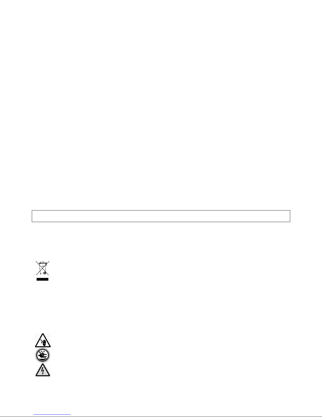
3. De DIP-schakelaars instellen
Duw op het lipje naast de camera en verwijder de koepel.
Om de camera te configureren, stel de DIP-schakelaars in op de printplaat.
Raadpleeg de figuur hieronder.
Gevaarlijke spanning!
Wees voorzichtig bij de installatie: raak geen kabels aan die onder stroom staan om
dodelijke
elektroshocks te vermijden.
Bescherm dit toestel tegen regen en vochtigheid.
Page 8

CAMCOLD5 - 8 - VELLEMAN
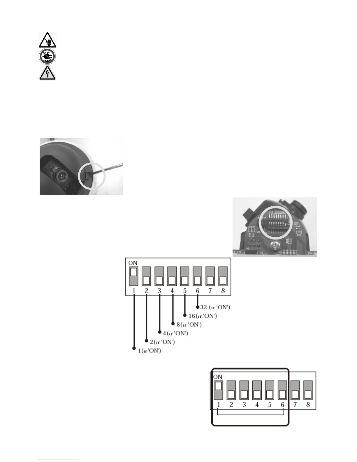
a. De camera-ID kiezen
• Stel het binair getal voor de camera-ID in (1 ~ 63 uitgenomen 0)
aan de hand van de DIP-schakelaars. Voorbeeld: Camera-ID als
10, stel de schakelaars als volgt in: 0 + 2 + 0 + 8 + 0.
• De standaard camera-ID is 1.
• Wanneer u de camera bestuurt via een bedieningspaneel, zorg er
dan voor dat de ID van de camera en het paneel identiek zijn.
Wenst u meer dan één camera te gebruiken, noteer dan de
camera-ID en de respectievelijke locatie.
b. Het protocol kiezen
• Ontkoppel de camera van de voeding alvorens het protocol te wijzigen.
• Kies het gepaste protocol aan de hand van de DIP-schakelaars.
Sch. 7 Sch. 8 Protocol / Snelheid
OFF OFF Pelco-D, 2400 bps
OFF ON Pelco-P, 4800 bps
ON OFF Pelco-D, 9600 bps
ON ON Pelco-P, 9600 bps
• Wenst u de camera via uw DVR of P/T controller te besturen, zorg dat het protocol van deze apparaten met het
protocol van de camera overeenstemt. Een verschil in protocol maakt de besturing onmogelijk.
• De standaard fabrieksinstelling is Pelco-D, 2400 bps.
• Druk op F4 op het bedieningspaneel en kies hetzelfde protocol als dat van de camera.
4. Montage
Zie Engelse handleiding vanaf pagina 3.
5. Aansluiting
Zie Engelse handleiding vanaf pagina 4.
Page 9

CAMCOLD5 - 9 - VELLEMAN
6. Opmerkingen
• Controleer de voedingskabel voor u de camera voedt.
• De camera-ID moet identiek zijn aan dat van de eigenlijke camera. Controleer daarom de DIP-schakelaars van de
camera.
• Zorg dat u het protocol van de controller aanpast aan dat van de camera indien de controller verscheidene
protocols ondersteunt.
• Een wijziging van het protocol via de DIP-schakelaars treedt pas in werking nadat u de camera heeft herstart.
• Raadpleeg de handleiding van elke controller indien de camera niet naar behoren werkt. Elke controller heeft een
verschillende configuratie.
7. De camera besturen
Zie Engelse handleiding vanaf pagina 4.
8. Problemen en oplossingen
Probleem Mogelijke oorzaak Oplossing
Verkeerde aansluiting. Controleer de aansluiting. De camera reageert niet wanneer u
de voeding aansluit.
Geen voeding. Controleer de voeding.
Verkeerde camera-ID of
overdrachtsnelheid.
Stel de camera-ID of
overdrachtsnelheid opnieuw in.
Verkeerd protocol. Stel het protocol opnieuw in.
De lichtsterkte en het beeld kunnen
niet worden bijgeregeld.
Verkeerde instelling van de RS485weerstand.
Stel de RS485-weerstand opnieuw
in.
Niet-compatibel protocol. Stel de DIP-schakelaars opnieuw in.
Verkeerde camera-ID. Stel de camera-ID opnieuw in.
Geen voeding. Controleer de voeding.
De camera kan niet worden bestuurd
/ onregelmatige beweging.
Verkeerde instelling van de RS485weerstand.
Stel de RS485-weerstand opnieuw
in.
Verkeerde zoominstelling. Stel de zoominstelling opnieuw in.
Onstabiel beeld.
Geen voeding. Controleer de voeding.
Focussering is manueel ingesteld. Laat een voorprogramma lopen of
stel de camera in.
Donker beeld.
Bevuilde lens. Maak de lens schoon.
9. Technische specificaties
Camera
Systeem PAL
Sensor 1/3” Sony Super HAD kleuren CCD
Pixels 512 (H) x 492 (V)
Horizontale resolutie 380 tv-lijnen
S/R verhouding ≥ 50dB
Lichtsterkte 0.5 lux / F1.4
Iris automatisch
Focussering 6mm
Backlight ON/OFF
Video-uitgang 1.0Vpp / 75Ω composiet
Sync System intern
AGC vast (0dB / 20dB)
Elektronische sluiter auto (1/60 – 1/100000s)
Page 10

CAMCOLD5 - 10 - VELLEMAN
Pan/Tilt
Automatisch scanbereik 5° ~ 350°
Snelheid Pan: 0.5°/s ~ 120°/s
Tilt: 0.5°/s ~ 45°/s
Presets 32
Communicatie RS485
Overdrachtsnelheid 9600 bit/s (WORLD protocol)
Protocol Pelco-P (9600 bps), Pelco-D (2400 bps)
Behuizing ABS gegoten plastic
Alarm 8 in / 4 out
Voeding 12VDC / 1A
Afmetingen Ø110 x 110mm
Gewicht 700g
Vochtigheidsgraad ≤ 95% RH
Opties bedieningspaneel via RS485 (CAMCOLD/CK)
montagebeugels (CAMCOLD/B2 en CAMCOLD/CB1)
10. Aansluitingsvoorbeeld
Zie figuur pagina 6.
De informatie in deze handleiding kan te allen tijde worden gewijzigd zonder voorafgaande kennisgeving.
CAMCOLD5 – CAMÉRA P/T DÔME COULEUR MINIATURE
1. Introduction
Aux résidents de l'Union européenne
Des informations environnementales importantes concernant ce produit
Ce symbole sur l'appareil ou l'emballage indique que l’élimination d’un appareil en fin de vie peut polluer
l'environnement.
Ne pas éliminer un appareil électrique ou électronique (et des piles éventuelles) parmi les déchets
municipaux non sujets au tri sélectif ; une déchetterie traitera l’appareil en question.
Renvoyer les équipements usagés à votre fournisseur ou à un service de recyclage local.
Il convient de respecter la réglementation locale relative à la protection de l’environnement.
Si vous avez des questions, contactez les autorités locales pour élimination.
Nous vous remercions de votre achat ! Lisez attentivement la présente notice avant la mise en service de l'appareil.
Si l’appareil a été endommagé pendant le transport, ne l'installez pas et consultez votre revendeur.
2. Prescriptions de sécurité
• La garantie ne s'applique pas aux dommages survenus en négligeant certaines directives de cette notice et votre
revendeur déclinera toute responsabilité pour les problèmes et les défauts qui en résultent.
• Confiez l'installation et l’entretien à un personnel qualifié.
• Toute modification de l’appareil est interdite pour des raisons de sécurité.
• Les dommages occasionnés par des modifications à l'appareil par le client, ne tombent pas sous la garantie.
• Gardez votre CAMCOLD5 hors de la portée de personnes non qualifiées et de jeunes enfants.
Tension dangereuse !
Soyez prudent lors de l'installation : toucher un câble sous tension peut causer des électrochocs mortels.
Protégez l'appareil contre la pluie et l'humidité.
Page 11
CAMCOLD5 - 11 - VELLEMAN
3. Réglage des commutateurs DIP
Appuyez sur la languette à côté de la caméra et retirez le dôme.
Pour configurer la caméra, réglez les commutateurs DIP sur le circuit imprimé.
Consultez l’illustration ci-dessous.
a. Choisir l’ID de la caméra
• Instaurez le nombre binaire de l’ID de la caméra (1 ~ 63 excepté
0) à l’aide des commutateurs DIP. Exemple : l’ID a la valeur 10,
instauration des commutateurs comme suit : 0 + 2 + 0 + 8 + 0.
• La valeur par défaut est 1.
• Si vous désirez contrôler la caméra à partir d’une console, veillez à ce que l’ID de la caméra est celle de la
console soient identiques. Si vous utilisez plusieurs caméras, il est conseillé de noter l’ID de chaque caméra et la
localisation.
b. Choisir le protocole
• Coupez l’alimentation vers la caméra avant de modifier le protocole.
• Choisissez le protocole approprié à l’aide des commutateurs DIP.
DIP 7 DIP 8 Protocole / Vitesse
OFF OFF Pelco-D, 2400 bps
OFF ON Pelco-P, 4800 bps
ON OFF Pelco-D, 9600 bps
ON ON Pelco-P, 9600 bps
• Si vous désirez contrôler la caméra à partir de votre DVR ou
console P/T, veillez à ce que le protocole de ces appareils soit synchronisé avec le protocole de la caméra. Une
différence de protocole rendra le contrôle impossible.
Page 12

CAMCOLD5 - 12 - VELLEMAN
• Le protocole par défaut est le Pelco-D, 2400 bps.
• Enfoncez F4 sur la console de commande et sélectionnez le même protocole que celui de la caméra.
4. Montage
Voir notice en Anglais à la page 3.
5. Connexion
Voir notice en Anglais à la page 4.
6. Remarque
• Vérifiez le cordon d’alimentation avant de brancher la caméra.
• Contrôlez les commutateurs DIP de la caméra et vérifiez qu’ils soient correctement configurés.
• Veillez à synchroniser le protocole de la console de contrôle et celui de la caméra si la console supporte plusieurs
protocoles.
• Une modification du protocole n’a effet qu’après une réinitialisation de la caméra.
• Consultez la notice de la console si la caméra ne fonctionne pas convenablement. Chaque console est
configurée différemment.
7. Contrôle de la caméra
Voir notice en Anglais à la page 4.
8. Problèmes et solutions
Problème Cause possible Solution
Connexion incorrecte. Vérifiez la connexion. La caméra ne réagit pas lors d la
connexion de l’alimentation.
Alimentation défaillante. Vérifiez l’alimentation.
ID de la caméra ou vitesse de
transmission incorrecte.
Réinstaurez l’ID de la caméra ou la
vitesse de transmission.
Protocole incorrecte. Réinstaurez le protocole.
L’intensité lumineuse et l’image ne
peuvent pas être contrôlées.
Réglage de la résistance RS485
incorrect.
Réinstaurez la résistance RS485.
Protocole incompatible. Réinstaurez les commutateurs DIP.
ID de la caméra incorrecte. Réinstaurez l’ID de la caméra.
Alimentation défaillante. Vérifiez l’alimentation.
La caméra est incontrôlable /
mouvement irrégulier.
Réglage de la résistance RS485
incorrect.
Réinstaurez la résistance RS485.
Réglage du zoom incorrect. Réglez le zoom.
Image instable.
Alimentation défaillante. Vérifiez l’alimentation.
Focalisation réglée manuellement. Démarrez une présélection ou réglez
la focalisation. Image floue.
Objectif sale. Nettoyez l’objectif.
9. Spécifications techniques
Caméra
Système PAL
Capteur 1/3” Sony Super HAD CCD couleur
Pixels 512 (H) x 492 (V)
Résolution horizontale 380 lignes TV
Rapport S/B
≥ 50dB
Intensité lumineuse 0.5 lux / F1.4
Page 13
CAMCOLD5 - 13 - VELLEMAN
Iris automatique
Focalisation 6mm
Backlight ON/OFF
Sortie vidéo 1.0Vpp / 75Ω composite
Sync System interne
AGC fixe (0dB / 20dB)
Obturateur électronique auto (1/60 – 1/100000s)
Pan/Tilt
Balayage automatique 5° ~ 350°
Vitesse Pan : 0.5°/s ~ 120°/s
Tilt : 0.5°/s ~ 45°/s
Présélections 32
Communication RS485
Vitesse de transmission 9600 bit/s (protocole WORLD)
Protocole Pelco-P (9600 bps), Pelco-D (2400 bps)
Boîtier résine ABS
Alarme 8 in / 4 out
Alimentation 12VDC / 1A
Dimensions Ø110 x 110mm
Poids 700g
Taux d’humidité ≤ 95% RH
Options console de contrôle via RS485 (CAMCOLD/CK)
Supports de montage (CAMCOLD/B2 et CAMCOLD/CB1)
10. Exemple d’une connexion
Voir notice en Anglais à la page 6.
Toutes les informations présentées dans cette notice peuvent être modifiées sans notification préalable.
CAMCOLD5 – MINICÁMARA DOMO PT COLOR
1. Introducción
A los ciudadanos de la Unión Europea
Importantes informaciones sobre el medio ambiente concerniente a este producto
Este símbolo en este aparato o el embalaje indica que, si tira las muestras inservibles, podrían dañar el
medio ambiente.
No tire este aparato (ni las pilas eventuales) en la basura doméstica; debe ir a una empresa especializada
en reciclaje. Devuelva este aparato a su distribuidor o a la unidad de reciclaje local.
Respete las leyes locales en relación con el medio ambiente.
Si tiene dudas, contacte con las autoridades locales para residuos.
¡Gracias por haber comprado la CAMCOLD5! Lea atentamente las instrucciones del manual antes de usarla. Si el
aparato ha sufrido algún daño en el transporte no lo conecte a la red y póngase en contacto con su distribuidor.
2. Instrucciones de seguridad
• Daños causados por descuido de las instrucciones de seguridad de este manual invalidarán su garantía y su
distribuidor no será responsable de ningún daño u otros problemas resultantes.
¡Tensión peligrosa!
Cuidado durante la instalación: puede sufrir una peligrosa descarga eléctrica al tocar los cables con un
voltaje peligroso
.
No exponga este equipo a lluvia ni humedad.
Page 14

CAMCOLD5 - 14 - VELLEMAN
• La instalación y el mantenimiento deben ser realizados por personal especializado.
• Los daños causados por modificaciones no autorizadas, no están cubiertos por la garantía.
• Mantenga la CAMCOLD5 lejos del alcance de personas no capacitadas y niños.
3. Ajuste de los conmutadores DIP
Apriete la lengüeta del lateral de la cámara y quite el domo.
Para configurar la cámara, ajuste los conmutadores DIP del CI. Véase la
siguiente figura.
a. Seleccionar ID de la cámara
• Introduzca el número binario de ID de la cámara (1 ~ 63 salvo 0)
con los conmutadores DIP. Ejemplo: si ID tiene el valor 10,
seleccione los conmutadores de la siguiente manera: 0 + 2 + 0 +
8 + 0.
• ID por defecto es el valor 1.
• Si quiere controlar la cámara con una consola de control,
asegúrese de que el ID de la cámara y de la consola sea
idéntico. Si utiliza varias cámaras, apunte ID y la localización de
cada cámara.
b. Seleccionar el protocolo
• Desconecte la cámara antes de modificar el protocolo.
• Seleccione el protocolo adecuado con los conmutadores DIP.
DIP 7 DIP 8
Protocolo /
Velocidad
OFF OFF Pelco-D, 2400 bps
OFF ON Pelco-P, 4800 bps
ON OFF Pelco-D, 9600 bps
ON ON Pelco-P, 9600 bps
Page 15

CAMCOLD5 - 15 - VELLEMAN
• Si quiere controlar la cámara desde su DVR o consola P/T, asegúrese de que el protocolo de estos aparatos esté
sincronizado con el protocolo de la cámara. el control se volverá imposible si hay una diferencia de protocolo.
• El protocolo por defecto es el Pelco-D, 2400 bps.
• Pulse F4 en la consola de control y seleccione el mismo protocolo que el de la cámara.
4. Montaje
Véase en la página 3.
5. Conexión
Véase en la página 4.
6. Observación
• Verifique el cable de alimentación antes de conectar la cámara.
• Controle los conmutadores DIP de la cámara y verifique que estén configuradas de manera correcta.
• Asegúrese de que el protocolo de la consola y el protocolo e la cámara estén sincronizados si la consola soporta
varios protocolos.
• Una modificación del protocolo sólo se efectúa después de haber reinicializado la cámara.
• Consulte el manual del usuario de la consola si la cámara no funciona correctamente. Cada consola tiene una
configuración diferente.
7. Manejar la cámara
Véase en la página 4.
8. Solución de problemas
Problema Causa posible Solución
Conexión incorrecta. Verifique la conexión. La cámara no reacciona al conectar
la alimentación.
Alimentación defectuosa. Verifique la alimentación.
ID de la cámara o velocidad de
transmisión incorrecta.
Vuelva a seleccionar ID de la
cámara o la velocidad de
transmisión.
Protocolo incorrecto. Vuelva a seleccionar el protocolo.
Es imposible controlar la intensidad
luminosa y la imagen.
Ajuste incorrecto de la resistencia
RS485.
Vuelva a seleccionar la resistencia
RS485.
Protocolo incompatible. Vuelva a seleccionar los
conmutadores DIP.
ID incorrecto de la cámara. Vuelva a seleccionar ID de la
cámara.
Alimentación defectuosa. Verifique la alimentación.
Es imposible controlar la cámara /
movimiento irregular.
Ajuste incorrecto de la resistencia
RS485.
Vuelva a seleccionar la resistencia
RS485.
Ajuste incorrecto del zoom. Ajuste el zoom.
Imagen inestable.
Alimentación defectuosa. Verifique la alimentación.
Foco ajustado manualmente. Ejecute una preselección o ajuste el
foco.
Imagen oscura.
Óptica sucia. Limpie la óptica.
Page 16

CAMCOLD5 - 16 - VELLEMAN
9. Especificaciones
Cámara
Sistema PAL
Sensor de imágenes Sony Super HAD CCD color de 1/3”
Píxeles 512 (H) x 492 (V)
Resolución horizontal 380 líneas TV
Relación señal/ruido ≥ 50dB
Intensidad luminosa 0.5 lux / F1.4
Iris automático
Foco 6mm
Retroiluminación ON/OFF
Salida de vídeo 1.0Vpp / 75Ω compuesto
Sincronización interna
AGC fijo (0dB / 20dB)
Shutter electrónico automático (1/60 – 1/100000 seg.)
Pan/Tilt
Exploración automática 5° ~ 350°
Velocidad Pan: 0.5°/s ~ 120°/s
Tilt: 0.5°/s ~ 45°/s
Preselecciones 32
Comunicación RS485
Velocidad de transmisión 9600 bit/s (protocole WORLD)
Protocolo Pelco-P (9600 bps), Pelco-D (2400 bps)
Carcasa resina ABS
Alarma 8 in / 4 out
Alimentación 12VDC / 1A
Dimensiones Ø110 x 110mm
Peso 700g
Humedad ≤ 95% RH
Opciones Consola de control por RS485 (CAMCOLD/CK)
Soportes de montaje (CAMCOLD/B2 y CAMCOLD/CB1)
10. Ejemplo de una conexión
Véase en la página 6.
Se pueden modificar las especificaciones y el contenido de este manual sin previo aviso.
CAMCOLD5 – P/T DOME-FARBKAMERA
1. Einführung
An alle Einwohner der Europäischen Union
Wichtige Umweltinformationen über dieses Produkt
Dieses Symbol auf dem Produkt oder der Verpackung zeigt an, dass die Entsorgung dieses Produktes nach
seinem Lebenszyklus der Umwelt Schaden zufügen kann.
Entsorgen Sie die Einheit (oder verwendeten Batterien) nicht als unsortiertes Hausmüll; die Einheit oder
verwendeten Batterien müssen von einer spezialisierten Firma zwecks Recycling entsorgt werden.
Diese Einheit muss an den Händler oder ein örtliches Recycling-Unternehmen retourniert werden.
Respektieren Sie die örtlichen Umweltvorschriften.
Falls Zweifel bestehen, wenden Sie sich für Entsorgungsrichtlinien an Ihre örtliche Behörde.
Danke für Ihren Ankauf! Lesen Sie diese Bedienungsanleitung vor Inbetriebnahme sorgfältig durch. Überprüfen Sie,
ob Transportschäden vorliegen. Sollte dies der Fall sein, verwenden Sie das Gerät nicht.
Page 17
CAMCOLD5 - 17 - VELLEMAN
2. Sicherheitsvorschriften
• Bei Schäden, die durch Nichtbeachtung der Bedienungsanleitung verursacht werden, erlischt der
Garantieanspruch. Für daraus resultierende Folgeschäden übernimmt der Hersteller keine Haftung.
• Das Gerät muss von einem Fachmann installiert und gewertet werden.
• Bei Schäden, verursacht durch eigenmächtige Änderungen, erlischt der Garantieanspruch.
• Halten Sie Kinder und Unbefugte vom Gerät fern.
3. Die DIP-Schalter einstellen
Drücken Sie die Lasche neben der Kamera und entfernen Sie die Kuppel.
Zur Konfiguration der Kamera, stellen Sie die DIP-Schalter auf der Printplatte
ein. Siehe Abbildung unten.
a. Die Kamera-ID wählen
• Stellen Sie die Binärzahl für die Kamera-ID mit den DIP-Schaltern
ein (1 ~ 63 ausgenommen 0). Beispiel: Kamera-ID 10, stellen sie
die Schalter wie folgt ein: 0 + 2 + 0 + 8 + 0.
• Die standardmäßige Kamera-ID ist 1.
• Wenn Sie die Kamera über ein Bedienfeld steuern, sorgen Sie
dafür, dass die ID der Kamera und die des Bedienfeldes identisch
sind. Wenn Sie mehr als eine Kamera verwenden wollen,
notieren Sie sich die Kamera-ID und die entsprechende Stelle.
Lebensgefährliche Spannungen!
Seien Sie während der Ins
tallation sehr vorsichtig: berühren Sie keine spannungsführenden Leitungen
um elektrische Schläge zu vermeiden.
Das Gerät vor Regen und Feuchtigkeit schützen.
Page 18

CAMCOLD5 - 18 - VELLEMAN
b. Das Protokoll wählen
• Trennen Sie die Kamera vom Netz ehe Sie das Protokoll ändern.
• Wählen Sie das geeignete Protokoll mit den DIP-Schaltern.
Sch. 7 Sch. 8 Protokoll /
Geschwindigkeit
OFF OFF Pelco-D, 2400 bps
OFF ON Pelco-P, 4800 bps
ON OFF Pelco-D, 9600 bps
ON ON Pelco-P, 9600 bps
• Möchten Sie Ihre Kamera über DVR oder P/T Steuergerät steuern, sorgen Sie dafür, dass das Protokoll dieser
Geräte mit dem Protokoll der Geräte übereinstimmt. Ein Protokollunterschied macht die Steuerung unmöglich.
• Die Werkseinstellung ist Pelco-D, 2400 bps.
• Drücken Sie F4 im Steuergerät und wählen Sie dasselbe Protokoll als das der Kamera.
4. Montage
Siehe englische Bedienungsanleitung ab Seite 3.
5. Anschluss
Siehe englische Bedienungsanleitung ab Seite 4.
6. Bemerkungen
• Überprüfen Sie das Versorgungskabel bevor Sie die Kamera mit Strom versorgen.
• Die Kamera-ID muss identisch mit der, der eigentlichen Kamera sein. Überprüfen Sie deshalb die DIP-Schalter
der Kamera.
• Sorgen Sie dafür, dass Sie das Protokoll des Steuergerätes dem der Kamera anpassen wenn das Steuergerät
verschiedene Programme unterstützt.
• Eine Änderung des Protokolls über die DIP-Schalter wird erst aktiviert wenn Sie den Computer neu starten.
• Siehe die Bedienungsanleitung für jedes Steuergerät wenn die Kamera nicht korrekt funktioniert. Jedes
Steuergerät hat eine andere Konfiguration.
7. Die Kamera steuern
Siehe englische Bedienungsanleitung ab Seite 4.
8. Problemlösung
Problem mögliche Ursache Lösung
falscher Anschluss überprüfen Sie den Anschluss die Kamera reagiert nicht wenn Sie
die Stromversorgung anschließen.
keine Stromversorgung überprüfen Sie die Stromversorgung
falsche Kamera-ID oder
Übertragungsgeschwindigkeit
Stellen Sie die Kamera-ID oder die
Übertragungsgeschwindigkeit erneut
ein.
falsches Protokoll stellen Sie das Protokoll erneut ein
die Lichtstärke und das Bild können
nicht abgestimmt werden.
falsche Einstellung des RS485-
Widerstands
stellen Sie den RS485-Widerstand
erneut ein.
Page 19

CAMCOLD5 - 19 - VELLEMAN
nicht-kompatibles Protokoll stellen Sie die DIP-Schalter erneut
ein.
falsche Kamera-ID Stellen Sie die Kamera-ID erneut ein
keine Stromversorgung Überprüfen Sie die
Stromversorgung.
Kamera kann nicht gesteuert werden
/ unregelmäßige Bewegung
falsche Einstellung des RS485-
Widerstands
stellen Sie die Zoomfunktion erneut
ein
falsche Zoomeinstellung Überprüfen Sie die Stromversorgung
instabiles Bild
keine Stromversorgung Lassen Sie ein Vorprogramm
ablaufen oder stellen Sie die Kamera
ein
Fokussierung ist manuell eingestellt reinigen Sie das Objektiv
dunkles Bild
schmutziges Objektiv stellen Sie die Zoomfunktion erneut
ein
9. Technische Daten
Camera
System PAL
Sensor 1/3” Sony Super HAD CCD-Farbkamera
Pixel 512 (H) x 492 (V)
Horizontale Auflösung 380 TV-Zeilen
Signal/Rauschabstand ≥ 50dB
Lichtstärke 0.5 lux / F1.4
Blende automatisch
Fokussierung 6mm
Hintergrundbeleuchtung ON/OFF
Video-Ausgang 1.0Vpp / 75Ω composite
Sync System intern
AGC fest (0dB / 20dB)
Elektronischer Verschluss auto (1/60 – 1/100000s)
Schwenk/Neige
Automatischer Scanbereich 5° ~ 350°
Geschwindigkeit Neige 0.5°/s ~ 45°/s
Voreinstellungen 32
Kommunikation RS485
Übertragungsgeschwindigkeit 9600 bit/s (WORLD Protokoll)
Protokoll Pelco-P (9600 bps), Pelco-D (2400 bps)
Gehäuse ABS-Kunststoff, gegossen
Alarm 8 in / 4 out
Stromversorgung 12VDC / 1A
Abmessungen Ø110 x 110mm
Gewicht 700g
Feuchtigkeitsgrad ≤ 95% RH
Optionen Bedienfeld über RS485 (CAMCOLD/CK)
Montagebügel (CAMCOLD/B2 und CAMCOLD/CB1)
10.Anschlussbeispiel
Siehe Abb. Seite 6.
Alle Änderungen vorbehalten.
 Loading...