

Page 1
CAMCOLD4
PROFESSIONAL OUTDOOR COLOUR PTZ DOME CAMERA
PROFESSIONELE KLEUREN PTZ BUITENCAMERA
CAMÉRA COULEUR PTZ PROFESSIONELLE POUR USAGE À L’EXTÉRIEUR
CÁMARA DOMO PTZ COLOR PROFESIONAL PARA EXTERIORES
PROFESSIONELLE PTZ-DOME-FARBKAMERA FÜR DEN AUßENBEREICH
USER MANUAL
GEBRUIKERSHANDLEIDING
NOTICE D’EMPLOI
MANUAL DEL USUARIO
BEDIENUNGSANLEITUNG
Page 2

Page 3
CAMCOLD4_v2 VELLEMAN 3
CAMCOLD4 – PROFESSIONAL OUTDOOR COLOUR PTZ DOME CAMERA
1. Introduction
To all residents of the European Union
Important environmental information about this product
This symbol on the device or the package indicates that disposal of the device after its lifecycle could harm
the environment.
Do not dispose of the unit (or batteries) as unsorted municipal waste; it should be taken to a specialised
company for recycling.
This device should be returned to your distributor or to a local recycling service.
Respect the local environmental rules.
If in doubt, contact your local waste disposal authorities.
Thank you for buying the CAMCOLD4! Please read the manual thoroughly before bringing this device into service. If
the device was damaged in transit, don't install or use it and contact your dealer.
2. Safety Instructions
• Damage caused by disregard of certain guidelines in this manual is not covered by the warranty and the dealer
will not accept responsibility for any ensuing defects or problems.
• A qualified technician should install and service this device.
• Unplug the unit from the mains before cleaning. Use a damp cloth only. Do not use liquid or aerosol cleaners and
make sure no liquid penetrates the housing.
• Note that damage caused by user modifications to the device is not covered by the warranty.
• Keep the device away from children and unauthorised users.
3. General Guidelines
• All modifications of the device are forbidden for safety reasons.
• Be careful not to leave fingerprints on the clear dome as they can affect the picture quality. Clean the dome using
a soft cloth.
• Never place the camera on an unstable stand, tripod or bracket as the unit may fall, causing bodily injuries and/or
damage to surrounding objects.
• There are no user-serviceable parts.
• Contact your dealer for spare parts if necessary.
• Do not expose the camera to direct sunlight or strong light beams. The CCD lens could be permanently damaged.
• Do not try to open the housing and repair the camera if it does not respond correctly. Read this manual over again
and find out the defect.
• Do not shake the device. Avoid brute force when installing or operating the device. Install the camera in a place
without vibrations.
Be very careful during the installation: touching live wires can cause life-threatening electroshocks.
Keep this device away from rain and moisture.
Unplug the mains lead before opening the housing.
Presence of lethal voltage.
Page 4
CAMCOLD4_v2 VELLEMAN 4
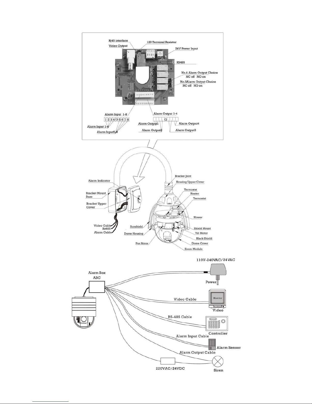
4. Description
Page 5
CAMCOLD4_v2 VELLEMAN 5
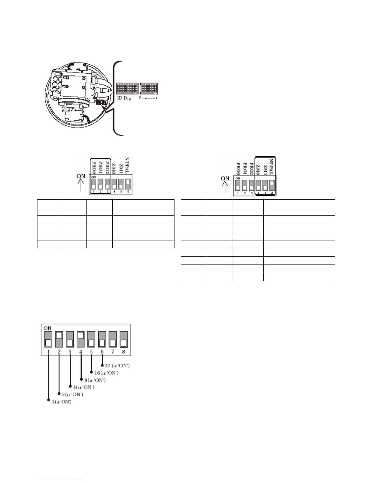
5. Setting the Protocol and the Camera ID
Before installing the camera, configure the camera ID and the communication protocol using the DIP switches.
There are two sets of DIP switches. Note that the default protocol is
Pelco-D with a baud rate of 2400 bps.
a. Protocol Setting
PRO0
Pin 1
PRO1
Pin 2
PRO2
Pin 3
Protocol / Baud
ZM1
Pin 4
ZM2
Pin 5
NT/PAL
Pin 6
Camera
OFF OFF OFF Pelco-D, 2400 bps OFF OFF OFF SONY X18, NTSC
ON OFF ON Pelco-D, 9600 bps OFF OFF OFF CNB X26, NTSC
OFF ON OFF Pelco-P, 4800 bps ON OFF OFF CNB X22, NTSC
ON ON ON Pelco-P, 9600 bps ON OFF OFF LG X27, NTSC
OFF ON ON SONY X18, PAL
OFF ON ON CNB X26, PAL
ON ON ON CNB X22, PAL
ON ON ON LG X27, PAL
Press F4 on the controller and select the same protocol as the one on the camera.
b. Camera ID Setting
Make sure the camera ID on the DIP switches and the camera ID on the
controller are identical. When controlling more than one camera, it is
recommended to memorize the IDs and the location of each camera.
By changing the DIP switch setting, you can set the binary number for each
camera ID (1 ~ 63, except 0). Default camera ID is 1. Example: Set the
camera ID as 10: 0 + 2 + 0 + 8 + 0.
c. RS485 Resistor
It is recommended to set the terminal resistor of the last camera in the series to ON. The switch is placed on the
alarm and connection board.
Page 6
CAMCOLD4_v2 VELLEMAN 6
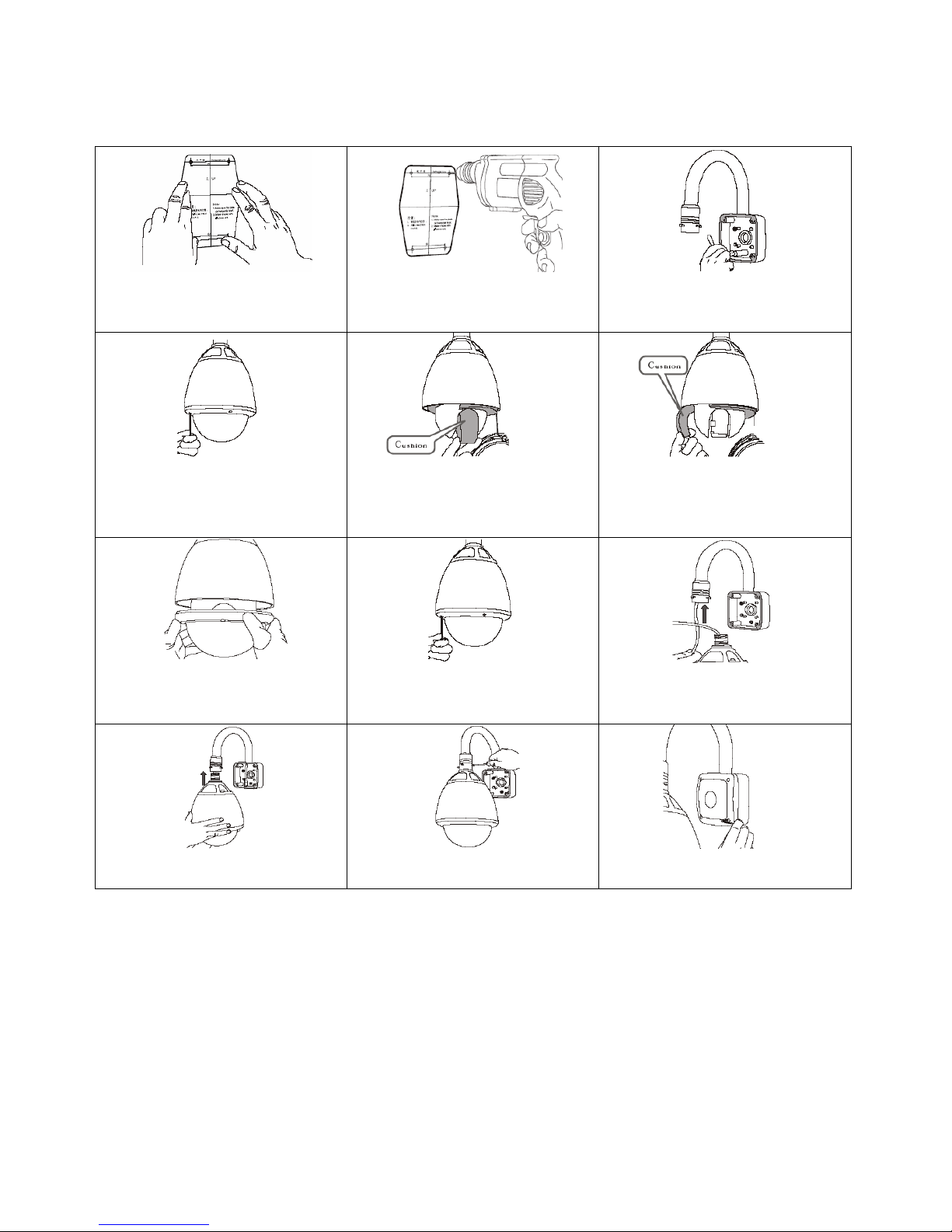
6. Installation
Wall Mounting
1. Stick the mounting pattern on the
desired installation spot.
2. Drill the mounting holes
according to the pattern.
3. Fix the mounting bracket base
onto the wall using the included
tools.
4. Remove the dome from the
housing wearing gloves so as not
to leave fingerprints.
5. Remove the cushions protecting
the lens.
6. Remove the cushions protecting
the camera. Remember to set the
DIP switches before closing the
dome.
7. Replace the dome on the
camera. Wear gloves so as not to
leave any fingerprints.
8. Pass the cable with the RJ45
connectors through the bracket.
9. Pass the cable with the RJ45
connectors through the bracket.
10. Fix the camera onto the bracket.
11. Fasten the included screws using
the included screwdriver.
12. Replace the cover and fasten it
with the included screws.
7. Controlling the CAMCOLD4 using a Keyboard
a. Selecting the Camera
• Choose a camera by pressing the camera number 1 – 255 and the CAM key.
• Press -1 to choose the previous camera or press +1 to choose the next camera.
Example: Selecting camera n° 2.
o Press 2 and the CAM key to select camera n° 2.
o After having selected the camera, press -1 to select the previous camera or press +1 to select the next
camera.
Page 7

CAMCOLD4_v2 VELLEMAN 7
b. Controlling the P/T and the Lens
• Select a camera (see “Selecting a Camera”).
• Press I-, I+, Z-, Z+, F- or F+ to control the P/T or tilt the joystick to control the lens.
Example: Controlling the P/T of camera n° 2.
o Press 2 and the CAM key to select camera n° 2.
o Tilt the joystick to control the camera P/T or use the I-, I+, Z-, Z+, F- or F+ key to control the lens.
c. Setting Up the Preset
• Select a camera and set the P/T and the lens to the desired position.
• Press the F1 key and press 8.
• Define the preset number (1 – 32).
• Press PRE to confirm.
Example: Setting preset 15 to camera n° 5.
o Press 5 and then press the CAM key to select the camera.
o Move the P/T and the lens to the desired position.
o Press the F1 key.
o Press 8.
o Press 15.
o Press PRE to confirm your selection.
d. Running the Preset
• Select the desired camera number.
• Define the preset (1 - 128). The default preset is 1.
• Press the CALL key. The corresponding preset will be displayed on the screen.
Example: Setting camera n° 3 to preset 6.
o Press 3.
o Press the CAM key.
o Press 6.
o Press the CALL key.
o Preset 6 of camera n° will be displayed.
e. Deleting a Preset
• Select the desired camera number and press the CAM key.
• Define the preset (1 - 128) and press the DEL key.
• The preset has been deleted.
Example: Deleting preset 2 of camera n° 3.
o Press 3.
o Press the CAM key.
o Press 2.
o Press the DEL key.
o The preset has been deleted.
Page 8

CAMCOLD4_v2 VELLEMAN 8
f. Camera Operation
• Calling up the OSD
o When in the OSD, press 96 and then the CALL key to set the dome camera. Tilt the joystick up or down to
select a menu item. Use F- to confirm or F+ to cancel.
• The Pattern
o Press a numeric key (1~4) and hold the SAL key pressed for more than 2 seconds to set a pattern. Press a
numeric key (1~4) and press the SAL key shortly to run the pattern.
• The Group
o Press a numeric key (21~28) and press the SAL key to run a predefined group (1~8). Use the OSD menu to
define or delete the group.
• Swing
o Press a numeric key (11~18) and press the SAL key to run a predefined swing movement (1~8) and use the
OSD menu to define or delete a swing pattern.
8. Controlling the CAMCOLD4 using the OSD
Before operating the camera, check following points:
• The camera ID of the controller must match the target camera ID. Check the DIP switches.
• If your controller supports multiple protocols, make sure the used protocol matches the camera’s protocol.
• Refer to the manual of the controller as each controller has different operating methods.
• Preset 96 is reserved to start the OSD menu. Therefore, preset 96 cannot be used as a regular camera preset.
The OSD Menu
Function: Configure the preset, group and alarm I/O function for each application.
To start the Menu: Press 96 and press the SWING PATTERN key.
• Preset
Function: Save up to 127 presets (1~128 except for 96).
Setting up a preset: Select the desired camera. Press the F1 key, press 8 and press enter the desired preset
number. Press the RRE key to confirm.
Running a preset: Select the desired camera. Enter the reset number (1~128) and press the CALL key to run the
corresponding preset.
Deleting a preset: Use the OSD menu.
• Swing
Function: Make a camera move between two preset positions. The speed can be selected from SLOW (15°/s),
NORMAL (30°/s) or FAST (60°/s).
Setting the swing pattern: Use the OSD menu.
Running a swing pattern: Press a key (11~18) and press the SAL key on the controller.
Deleting a swing pattern: Use the OSD menu.
• Pattern
Function: Create and save specific camera movements defined with the joystick. Maximum 4 one-minute patterns
can be stored.
Setting the pattern: Using the controller, press a numeric key (1~4) and hold the SAL key pressed for more than 2
seconds. Move the camera using the joystick and create your scan pattern. Maximum recording
Page 9
CAMCOLD4_v2 VELLEMAN 9
time is 1 minute. The remaining time will be displayed on screen in a percentage. Save the
pattern using the F- key. Cancel the pattern using the F+. You can also use the OSD menu.
Running a pattern: Choose a pattern (1~4) and press the SAL key.
Deleting a pattern: Use the OSD menu.
• Group
Function: The group function allows you to run a sequence of presets, patterns or swing movements. You can store
up to 8 groups each with a max. of 20 actions. The group can be created, modified or deleted using the
menu. The dwell time defined in the preset is effective when the group is running.
Setting the group: Use the OSD menu.
Running the group: Press a numeric key (21~28) to choose the group and press the SAL key on the controller.
Example: If your group number is 5, press 25 and the SAL key.
Deleting a group: Use the OSD menu.
• Other functions
Power-up action: This function enables you to recover the last action before the camera shut down.
Auto-flip 180°: If the tilt angle exceeds 90°, the pan is automatically moved into the opposite direction so the target is
continuously tracked.
Park action: This function enables you to point the camera at a specific target. The interval can be defined from 1
minute up to 4 hours.
Original position: Define the original position. The pan angle can be modified changing the original position. However,
the tilt angle will not be affected.
Alarm I/O: Using the optional alarm I/O module, 8 alarm inputs and 4 outputs will be available. If an external sensor is
activated, the camera can be set to move to a preset position. The output relay can be programmed to
take actions as e.g. turning on the light or activating the alarm. Note that the latest alarm input is effective
if multiple sensors have been activated.
Privacy mask: To ensure the privacy, you can create up to 8 white masks so objects such as windows can be hidden.
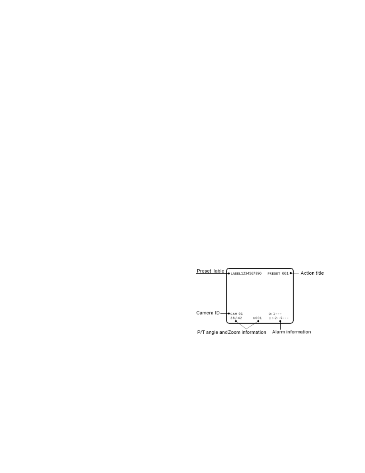
The OSD Display of the Main Screen
PTZ information: Current pan/tilt angle in degrees and zoom
magnification.
Camera ID: Current camera ID.
Preset table: The label stored for a specific preset.
Action title: SPRESETxxx: Preset xxx is stored.
PRESETxxx: Camera has reached preset xxx.
UNDEFINED: Ana undefined preset number is
called.
SWINGxxx: Swing xxx is active.
Alarm Information: Current state of the alarm I/O. Example above: Output 1 is active, inputs 2 and 5 are active.
General Rules when Operating the Menu
• Menu items between (brackets) always have a submenu.
• To access a submenu, press F-, to exit the menu press F+.
• Use the joystick (up, down, left or right) to move from item to item.
• Confirm pressing F-.
• To modify a value, use the joystick (up, down, left or right), press F- to save the modification or press F+ to
cancel.
Page 10

CAMCOLD4_v2 VELLEMAN 10
Main menu
Display Setup
This menu enables you to show or hide the OSD menu. An item set on AUTO will only
be displayed when modified.
Camera Setup
Set up the general functions of the camera. Tilt the joystick up or down to select the
mode. If the LINE LOCK is activated, the video signal is synchronized with the AC
power. The video can fluctuate after a modification. RESET CAMERA will reinitialize the
camera.
P/T motion setup
Set up the general functions of the pan/tilt movement. The max. JOG SPEED is listed below with a 1x zoom. As the
zoom magnification is increased, the speed will be decreased so the camera will be controllable.
FAST 0°~160°/s
NORMAL 0°~80°/s
SLOW 0°~40°/s
If you inverse the JOG DIRECTION, the screen will move in the same direction as the
jog tilt direction. A normal JOG DIRECTION will invert the direction.
PARK action setup
This function enables you to point the camera at a specific target. The time is displayed
in an hh:mm:ss format and can be modified.
Original position setup
Redefine a particular pan position to the original position. In the SET ORIGIN
POSITION submenu, you can move the pan position using the joystick and redefine the
original position.
Alarm input setup
Match the alarm sensor to one of the preset positions. If an external sensor is activated,
the camera will move to the corresponding preset position.
Page 11

CAMCOLD4_v2 VELLEMAN 11
Preset setup
Select a preset which you can create or modify. If the current preset number was
predefined, the camera will move to the stored position and automatically zoom. In the
other case, UNDEFINED will be displayed. The DWELL TIME will be displayed in an
hh:mm:ss format.
Edit relay out
Define the relay output. If an output relay is activated (ON), the number corresponding to
each point will appear. You can set relay outputs per preset.
Edit present label
Edit a name for each preset. The label can be up to 15 characters long and will be
automatically displayed in the upper left corner of the screen. Use the joystick (up, down,
left or right) to move the cursor to the appropriate character. Delete a previous character
using the ← symbol. Press OK when the name is complete and press F- to confirm.
Move the cursor to CANCEL and press F+ to abort the modification.
Edit a preset scene
Use the joystick and move the camera to desired position. Press F- to save the current
PTZ data. Press F+ to cancel the PTZ data.
Pattern setup
Select the pattern number to edit. If the pattern number does not exist, UNDEFINED will
be displayed. You can record a pattern under PROGRAM PATTERN.
Record pattern
Use the joystick and the camera to the starting position and the desired zoom. To start
recording the pattern, press F-. To exit the menu, press F+. The recorded data will be
lost. Maximum recording time is 1 minute. The remaining recording time will be displayed
in a percentage.
Swing setup
Select the swing number which you desire to create or modify. If the current swing number is not defined,
UNDEFINED SWING will be mentioned. Define the two preset positions for the swing motion. UNDEFINED PRESET
means you have assigned an undefined value for one of the positions. The SWING
SPEED can also be set. Refer to the table below.
FAST 60°/s
NORMAL 30°/s
SLOW 15°/s
The LOOP represents the number of swing motions effectuated by the camera within a group.
Page 12

CAMCOLD4_v2 VELLEMAN 12
Group setup
x000 means no action has been selected. If you assign a preset, it will show
p001~p128; if you assign a swing motion, it will show s1~s8; if you assign a pattern, it
will show t1~t4. CLEAR GROUP will delete all 20 entries.
Setup action
Select the desired group number using the joystick
and press F- to modify.
Use the joystick to select an entity to be modified.
Press F-.
Select the proper action (x, s, t or p) using the
joystick. Press F-. If you press F+ the modified value
will be ignored.
When completed, move to OK and press F- to finish.
Privacy mask setup
Enable or disable the display of the masking. Program the zone in the SET PRIVACY
MASK submenu.
Privacy zone setup
Move to the scene to hide using the joystick. Adjust the zoom since the mask will be
created at full screen size. When finished masking, press F- to confirm or press F+ to
cancel. The mask will now be displayed. Press F- to save or F+ to cancel. After you exit
the menu, you will notice the mask whenever you move to the zone the mask is
assigned to. The number in the centre represents the mask number. Max. 8 zones can
be assigned. Note that the zone can be a little misaligned since the OSD display is
relatively slow and the minimum resolution is limited.
Page 13

CAMCOLD4_v2 VELLEMAN 13
9. Troubleshooting
Problem Possible Cause Solution
The camera does not react when
connected to a power supply.
Wrong connection. Check the connection.
Power deficiency. Check the power supply.
Pan and tilt cannot be controlled.
Wrong camera ID or baud rate. Reset the camera ID or baud rate.
Too many domes on the RS485
cable.
Use a RS485 distributor.
Wrong protocol. Reset the protocol.
Low-quality RS485 cable. Use a high-quality RS485 cable.
Bad RS485 connection. Check the connection with the
RS485.
Wrong RS485 terminator setting. Reset the RS485 terminator setting.
Initializing failure.
Pan or tilt switch fault. Replace the switch.
Power deficiency. Check the power supply or use a
thicker wire.
Wrong DIP setting. Modify the DIP switch setting.
No video signal.
Wrong video connection. Check the connection.
Loose cable. Plug the cable correctly.
Zoom module fault. Replace the zoom module.
Fluctuating image.
Wrong zoom setting. Reset the zoom setting.
Power deficiency. Check the power supply.
Dimmed image.
Focus is manually set. Run a preset or set the camera.
Dirty lens or dome. Clean the lens and the dome.
10. Technical Specifications
Camera
System PAL/NTSC
Sensor 1/4" Sony Super HAD colour CCD
Number of Pixels 752 (H) x 582 (V)
Horizontal Resolution 480 TV lines
Video S/N Ratio ≥48dB
Zoom 27 x optical (f=3.25-88mm) 10 x digital zoom
Min. Illumination 1lux (normal), 0.01 lux (DSS) / F1.4
Day / Night auto
Iris auto/manual
Focus auto/manual
White Balance auto/manual
Backlight Compensation on/off
Video Output Level 1.0Vpp / 75Ω, composite
Synchronizing System internal
Gamma Correction 0.45
Auto Gain Control max. 29dB
Electronic Shutter Control auto (1/50-1/100000s) / flickerless mode
Pan / Tilt
Swing Angle pan: 360° continuous; tilt: 90°
Swing Speed pan: 0.05°/s ~ 180°/s (proportional to zoom)
Presets 127 (max. preset speed: 400°/s)
Pattern 4 channels each (speed: 0.1°/s ~ 180°/s)
Swing 8 channels each (speed: 15°/s ~ 60°/s)
Group each with 20 actions like preset, pattern and swing
Communication RS485
Page 14

CAMCOLD4_v2 VELLEMAN 14
Baud Rate max. 9600 bit/s (WORLD protocol)
Protocol Pelco-P (9600 bps), Pelco-D (2400 bps)
Housing ABS cast plastic
Others
Power Supply 24VDC / 3A
Power Consumption 20W
Dimensions Ø214 x 260mm (dome: Ø130mm)
Weight 1.5kg
Working temperature -35°C ~ 50°C
Max. Humidity 95% RH
Options controller keyboard via RS485 (CAMCOLD/CK)
For more info concerning this product, please visit our website www.velleman.eu.
The information in this manual is subject to change without prior notice.
CAMCOLD4 – PROFESSIONELE KLEUREN PTZ BUITENCAMERA
1. Inleiding
Aan alle ingezetenen van de Europese Unie
Belangrijke milieu-informatie betreffende dit product
Dit symbool op het toestel of de verpakking geeft aan dat, als het na zijn levenscyclus wordt weggeworpen,
dit toestel schade kan toebrengen aan het milieu.
Gooi dit toestel (en eventuele batterijen) niet bij het gewone huishoudelijke afval; het moet bij een
gespecialiseerd bedrijf terechtkomen voor recyclage.
U moet dit toestel naar uw verdeler of naar een lokaal recyclagepunt brengen.
Respecteer de plaatselijke milieuwetgeving.
Hebt u vragen, contacteer dan de plaatselijke autoriteiten inzake verwijdering.
Dank u voor uw aankoop! Lees deze handleiding grondig voor u het toestel in gebruik neemt. Werd het toestel
beschadigd tijdens het transport, installeer het dan niet en raadpleeg uw dealer.
2. Veiligheidsinstructies
• De garantie geldt niet voor schade door het negeren van bepaalde richtlijnen in deze handleiding en uw dealer zal
de verantwoordelijkheid afwijzen voor defecten of problemen die hier rechtstreeks verband mee houden.
• Laat dit toestel installeren en onderhouden door een geschoolde technicus.
• Trek de stekker uit het stopcontact voordat u het toestel reinigt. Gebruik een vochtige doek. Vermijd gebruik van
vloeibare reinigingsproducten en sproeiers en zorg dat er geen vloeistof in de behuizing kan doordringen.
• Schade door wijzigingen die de gebruiker heeft aangebracht aan het toestel vallen niet onder de garantie.
• Houd dit toestel uit de buurt van kinderen en onbevoegden.
Wees voorzichtig bij de installatie: raak geen kabels aan die onder stroom staan om dodelijke elektroshocks
te vermijden.
Gevaarlijke spanning!
Bescherm dit toestel tegen regen en vochtigheid.
Verzeker u ervan dat het toestel niet aangesloten is op een stroombron alvorens het te openen.
Page 15

CAMCOLD4_v2 VELLEMAN 15
3. Algemene richtlijnen
• Om veiligheidsredenen mag de gebruiker geen wijzigingen aanbrengen aan het toestel.
• Laat geen vingerafdrukken na op de koepel. Vingerafdrukken kunnen het opgenomen beeld negatief
beïnvloeden. Maak de koepel schoon met een zachte doek.
• Plaats de camera nooit op een onstabiele voet, driepoot of montagebeugel om te vermijden dat de camera valt en
beschadiging aan omliggende objecten of lichamelijke letsels veroorzaakt.
• De gebruiker mag geen onderdelen vervangen.
• Bestel eventuele reserveonderdelen bij uw dealer.
• Stel het toestel niet bloot aan direct zonlicht of sterke lichtstralen zodat de CCD-lens niet beschadigd kan worden.
• Open de behuizing niet en probeer de camera niet zelf te repareren wanneer ze niet naar behoren werkt. Herlees
de handleiding en probeer het defect te ontdekken.
• Schud het toestel niet dooreen. Vermijd brute kracht tijdens de installatie en de bediening van dit toestel.
Installeer het toestel op een plaats waar geen trillingen voorkomen.
4. Omschrijving
Zie figuren in de Engelse handleiding op pagina 2.
5. Het protocol en de camera-ID instellen
Alvorens de camera te installeren, configureert u best de camera, de ID van de camera en het protocol aan de hand
van de DIP-schakelaars.
Er zijn twee reeksen DIP-schakelaars. Het standaard protocol is
het Peclo-D protocol met een overdrachtsnelheid van 2400 bps.
a. Het protocol instellen
PRO0
Pin 1
PRO1
Pin 2
PRO2
Pin 3
Protocol / Snelheid
ZM1
Pin 4
ZM2
Pin 5
NT/PAL
Pin 6
Camera
OFF OFF OFF Pelco-D, 2400 bps OFF OFF OFF SONY X18, NTSC
ON OFF ON Pelco-D, 9600 bps OFF OFF OFF CNB X26, NTSC
OFF ON OFF Pelco-P, 4800 bps ON OFF OFF CNB X22, NTSC
ON ON ON Pelco-P, 9600 bps ON OFF OFF LG X27, NTSC
OFF ON ON SONY X18, PAL
OFF ON ON CNB X26, PAL
ON ON ON CNB X22, PAL
ON ON ON LG X27, PAL
Druk op F4 op het bedieningspaneel en kies hetzelfde protocol als dat van de camera.
Page 16

CAMCOLD4_v2 VELLEMAN 16
b. Instellen van de camera-ID
Zorg ervoor dat de ID van de camera op de camera (DIP-schakelaars) en op het
controlepaneel identiek zijn. Wanneer u meer dan één camera wenst te besturen,
is het aanbevolen van de ID en de locatie van elke camera te noteren.
Door de DIP-schakelaars te wijzigen, kunt u het binaire nummer van elke cameraID instellen (1 ~ 63, uitgenomen 0). De standaard camera-ID is 1. Voorbeeld: Stel
de camera in als 10: 0 + 2 + 0 + 8 + 0.
c. De eindweerstand van de RS485
Het is aanbevolen de eindweerstand van de laatste camera in de serie in te schakelen (ON). De schakelaar bevindt
zich op het aansluitingsbord van de camera.
6. Installatie
Zie Engelse handleiding op pagina 4.
7. Uw CAMCOLD4 besturen vanaf het controlepaneel
Zie Engelse handleiding vanaf pagina 4.
8. Uw CAMCOLD4 besturen vanaf de OSD
Zie Engelse handleiding vanaf pagina 6.
9. Problemen en oplossingen
Probleem Mogelijke oorzaak Oplossing
De camera reageert niet wanneer u
de voeding aansluit.
Verkeerde aansluiting. Controleer de aansluiting.
Geen voeding. Controleer de voeding.
Pan en tilt kunnen niet bestuurd
worden.
Verkeerde camera-ID of
overdrachtsnelheid.
Stel de camera-ID of
overdrachtsnelheid opnieuw in.
Te veel camera’s op de RS485kabel aangesloten.
Gebruik een RS485-verdeler.
Verkeerd protocol. Stel het protocol opnieuw in.
RS485-kabel van minderwaardige
kwaliteit.
Gebruik een hoogwaardige RS485-
kabel.
Slechte RS485-aansluiting. Controleer de RS485-aansluiting.
Verkeerde instelling eindweerstand. Stel de RS485-weerstand opnieuw
in.
Fout bij het initialiseren.
Fout van de pan- of tiltschakelaar. Vervang de schakelaar.
Geen voeding. Controleer de voeding of gebruik
een dikkere kabel.
Verkeerde DIP-instelling. Wijzig de DIP-instelling.
Geen videosignaal.
Verkeerde videoaansluiting. Controleer de aansluiting.
Kabel niet goed aangesloten. Sluit de kabel correct aan.
Fout van de zoommodule. Vervang de zoommodule.
Onstabiel beeld.
Verkeerde zoominstelling. Stel de zoominstelling opnieuw in.
Geen voeding. Controleer de voeding.
Donker beeld.
Focussering is manueel ingesteld. Laat een voorprogramma lopen of
stel de camera in.
Bevuilde lens. Maak de lens schoon.
Page 17

CAMCOLD4_v2 VELLEMAN 17
10. Technische specificaties
Camera
Systeem PAL/NTSC
Sensor 1/4" Sony Super HAD kleuren CCD
Pixels 752 (H) x 582 (V)
Horizontale resolutie 480 tv-lijnen
S/R verhouding ≥48dB
Zoom 27 x optische (f=3.25-88mm) 10 x digitale zoom
Min. verlichting 1lux (normaal), 0.01 lux (DSS) / F1.4
Dag / Nacht automatisch
Iris automatisch/manueel
Focussering automatisch/manueel
Witbalans automatisch/manueel
Tegenlichtcompensatie on/off
Uitgangsniveau video 1.0Vpp / 75Ω, composiet
Sync systeem intern
Gammacorrectie 0.45
Auto Gain Control max. 29dB
Elektronische sluiter auto (1/50-1/100000s) / flickerless mode
Pan / Tilt
Hoek pan: 360° continue rotatie; tilt: 90°
Snelheid pan: 0.05°/s ~ 180°/s (proportioneel tot zoom)
Presets 127 (max. snelheid: 400°/s)
Pattern 4 kanalen elk (snelheid: 0.1°/s ~ 180°/s)
Swing 8 kanalen elk (snelheid: 15°/s ~ 60°/s)
Group elk met 20 handelingen zoals preset, pattern en swing
Communicatie RS485
Overdrachtsnelheid max. 9600 bit/s (WORLD-protocol)
Protocol Pelco-P (9600 bps), Pelco-D (2400 bps)
Behuizing ABS gegoten plastic
Andere
Voeding 24VDC / 3A
Verbruik 20W
Afmetingen Ø214 x 260mm (koepel: Ø130mm)
Gewicht 1.5kg
Werktemperatuur -35°C ~ 50°C
Max. Vochtigheidsgraad 95% RH
Opties controlepaneel via RS485 (CAMCOLD/CK)
Voor meer informatie omtrent dit product, zie www.velleman.eu.
De informatie in deze handleiding kan te allen tijde worden gewijzigd zonder voorafgaande kennisgeving.
CAMCOLD4 – CAMÉRA COULEUR PTZ PROFESSIONELLE POUR USAGE À L’EXTÉRIEUR
1. Introduction
Aux résidents de l'Union européenne
Des informations environnementales importantes concernant ce produit
Ce symbole sur l'appareil ou l'emballage indique que l’élimination d’un appareil en fin de vie peut polluer
l'environnement.
Ne pas éliminer un appareil électrique ou électronique (et des piles éventuelles) parmi les déchets
municipaux non sujets au tri sélectif ; une déchetterie traitera l’appareil en question.
Renvoyer les équipements usagés à votre fournisseur ou à un service de recyclage local.
Il convient de respecter la réglementation locale relative à la protection de l’environnement.
Si vous avez des questions, contactez les autorités locales pour élimination.
Page 18

CAMCOLD4_v2 VELLEMAN 18
Nous vous remercions de votre achat ! Lisez attentivement la présente notice avant la mise en service de l'appareil.
Si l’appareil a été endommagé pendant le transport, ne l'installez pas et consultez votre revendeur.
2. Prescriptions de sécurité
• La garantie ne s'applique pas aux dommages survenus en négligeant certaines directives de cette notice et votre
revendeur déclinera toute responsabilité pour les problèmes et les défauts qui en résultent.
• Confiez l'installation et l’entretien à un personnel qualifié.
• Débranchez l’appareil s’il n’est pas utilisé ou pour le nettoyer. Utilisez un chiffon humide. Évitez l’usage de
détergents liquides et de vaporisateurs et veillez à ce qu’aucun liquide ne puisse pénétrer le boîtier.
• Les dommages occasionnés par des modifications à l'appareil par le client, ne tombent pas sous la garantie.
• Gardez votre CAMCOLD4 hors de la portée de personnes non qualifiées et de jeunes enfants.
3. Directives générales
• Toute modification de l’appareil est interdite pour des raisons de sécurité.
• Évitez de laissez des marques de doigt sur le dôme. Des marques de doigt peuvent influencer l’image de manière
négative. Nettoyez le dôme avec un chiffon humide.
• N’installez jamais la caméra sur un statif, un trépied ou un support de montage instable pour éviter qu’elle tombe
et cause des endommagements à des objets adjacents ou des blessures corporelles.
• Il n’y a aucune pièce maintenable par l’utilisateur.
• Commandez des pièces de rechange éventuelles chez votre revendeur.
• N’exposez pas l’appareil aux rayons directs du soleil ou des rayons lumineux intensifs pour éviter que l’objectif
CCD s’endommage.
• N’ouvrez pas le boîtier et n’essayez jamais de réparer la caméra en cas de défaut. Relisez la notice et essayez
de déceler le problème.
• Évitez de secouer l'appareil et traitez l'appareil avec circonspection pendant l'installation et l'opération. Installez
cet appareil à un endroit à l’abri de vibrations.
4. Description
Voir la notice en Anglais à la page 2.
5. Établir le protocole et l’ID de la caméra
Avant d’installer la caméra, configurez la caméra, l’ID de la caméra
et le protocole à l’aide des commutateurs DIP.
Il y a deux rangés de commutateurs DIP. Le protocole par défaut
est le protocole Peclo-D avec une vitesse de transmission de 2400
bps.
Soyez prudent lors de l'installation : toucher un câble sous tension peut causer des électrochocs mortels.
Tension dangereuse !
Protégez l'appareil contre la pluie et l'humidité.
Débranchez le câble d'alimentation avant d'ouvrir le boîtier.
Page 19

CAMCOLD4_v2 VELLEMAN 19
a. Établir le protocole
PRO0
DIP 1
PRO1
DIP 2
PRO2
DIP 3
Protocole / Vitesse
ZM1
DIP 4
ZM2
DIP 5
NT/PAL
DIP 6
Caméra
OFF OFF OFF Pelco-D, 2400 bps OFF OFF OFF SONY X18, NTSC
ON OFF ON Pelco-D, 9600 bps OFF OFF OFF CNB X26, NTSC
OFF ON OFF Pelco-P, 4800 bps ON OFF OFF CNB X22, NTSC
ON ON ON Pelco-P, 9600 bps ON OFF OFF LG X27, NTSC
OFF ON ON SONY X18, PAL
OFF ON ON CNB X26, PAL
ON ON ON CNB X22, PAL
ON ON ON LG X27, PAL
Enfoncez F4 sur la console de commande et sélectionnez le même protocole que celui de la caméra.
b. Établir l’ID de la caméra
Veillez à ce que l’ID sur la caméra (commutateurs DIP) celui sur le panneau
de contrôle soient identiques. Si vous désirez contrôler plusieurs caméras, il
est conseillé de noter l’ID et la localisation de chaque caméra.
En modifiant les commutateurs DIP il est possible d’établir le nombre binaire
de chaque caméra (1 ~ 63, excepté 0). L’ID de caméra par défaut est 1.
Exemple : Établir la caméra comme 10: 0 + 2 + 0 + 8 + 0.
c. La résistance de terminaison RS485
Il est recommandé d’activer (« ON ») la résistance de terminaison de la dernière caméra dans la série. Le
commutateur se trouve sur le circuit imprimé de chaque caméra.
6. Installation
Voir la notice en Anglais à la page 4.
7. Contrôler votre CAMCOLD4 à partir du panneau de contrôle
Voir la notice en Anglais à la page 4.
8. Contrôler votre CAMCOLD4 à partir de l’OSD
Voir la notice en Anglais à la page 6.
Page 20

CAMCOLD4_v2 VELLEMAN 20
9. Problèmes et solutions
Problème Cause possible Solution
La caméra ne réagit pas lors d la
connexion de l’alimentation.
Connexion incorrecte. Vérifiez la connexion.
Alimentation défaillante. Vérifiez l’alimentation
Pan et tilt incontrôlables.
ID de la caméra ou vitesse de
transmission incorrecte.
Réinstaurez l’ID de la caméra ou la
vitesse de transmission.
Trop de dômes connectés sur le
câble RS485.
Utilisez un distributeur RS485.
Protocole incorrecte. Réinstaurez le protocole.
Câble RS485 de basse qualité. Utilisez un câble RS485 de haute
qualité.
Connexion RS485 incorrecte. Vérifiez la connexion RS485.
Réglage de la résistance RS485
incorrect.
Rétablissez le réglage e la
résistance RS485.
Faute de réinitialisation.
Faute de l’interrupteur pan ou tilt. Remplacez l’interrupteur.
Alimentation défaillante. Vérifiez l’alimentation ou utilisez un
câble plus épais.
Réglage DIP incorrect. Modifiez le réglage des
commutateurs DIP.
Pas de signal vidéo.
Connexion vidéo incorrecte. Vérifiez la connexion.
Câble mal connecté. Connectez la câble de manière
correcte.
Faute du module zoom. Remplacez le module.
Image instable.
Réglage du zoom incorrect. Réglez le zoom.
Alimentation défaillante. Vérifiez l’alimentation
Image floue.
Focalisation réglée manuellement. Démarrez une présélection ou réglez
la focalisation.
Objectif sale. Nettoyez l’objectif.
10. Spécifications techniques
Caméra
Système PAL/NTSC
Capteur CCD couleur 1/4" Sony Super HAD
Pixels 752 (H) x 582 (V)
Résolution horizontale 480 lignes TV
Rapport S/B ≥48dB
Zoom 27x zoom optique (f=3.25-88mm) 10x zoom numérique
Intensité lumineuse 1 lux (normal), 0.01 lux (DSS) / F1.4
Jour / nuit automatique
Iris automatique/manuel
Focalisation automatique/manuel
Balance des blancs automatique/manuel
Compensation de contre-jour on/off
Niveau de sortie vidéo 1.0Vpp / 75Ω, composite
Sync systeem interne
Correction gamma 0.45
Contrôle automatique du gain max. 29dB
Obturateur électronique auto (1/50-1/100000s) / mode « flickerless »
Page 21

CAMCOLD4_v2 VELLEMAN 21
Pan / Tilt
Angle pan : 360° rotation continue ; tilt : 90°
Vitesse pan : 0.05°/s ~ 180°/s (en proportion du zoom)
Présélections 127 (vitesse max. : 400°/s)
Pattern 4 canaux pour chaque (vitesse : 0.1°/s ~ 180°/s)
Swing 8 canaux pour chaque (vitesse : 15°/s ~ 60°/s)
Groupe chaqu’une avec 20 actions comme présélection, pattern et swing
Communication RS485
Vitesse de transmission max. 9600 bit/s (protocole WORLD)
Protocole Pelco-P (9600 bps), Pelco-D (2400 bps)
Boîtier résine ABS
Autres
Alimentation 24VCC / 3A
Consommation 20W
Dimensions Ø214 x 260mm (dôme : Ø130mm)
Poids 1.5kg
Température de service -35°C ~ 50°C
Taux d’humidité 95% RH
Options panneau de contrôle via RS485 (CAMCOLD/CK)
Pour plus d’information concernant cet article, visitez notre site web www.velleman.eu.
Toutes les informations présentées dans cette notice peuvent être modifiées sans notification préalable.
CAMCOLD4 – CÁMARA DOMO PTZ COLOR PROFESIONAL PARA EXTERIORES
1. Introducción
A los ciudadanos de la Unión Europea
Importantes informaciones sobre el medio ambiente concerniente a este producto
Este símbolo en este aparato o el embalaje indica que, si tira las muestras inservibles, podrían dañar el
medio ambiente.
No tire este aparato (ni las pilas, si las hubiera) en la basura doméstica; debe ir a una empresa
especializada en reciclaje. Devuelva este aparato a su distribuidor o a la unidad de reciclaje local.
Respete las leyes locales en relación con el medio ambiente.
Si tiene dudas, contacte con las autoridades locales para residuos.
¡Gracias por haber comprado la CAMCOLD4! Lea atentamente las instrucciones del manual antes de usarla. Si el
aparato ha sufrido algún daño en el transporte no lo conecte a la red y póngase en contacto con su distribuidor.
2. Instrucciones de seguridad
• Daños causados por descuido de las instrucciones de seguridad de este manual invalidarán su garantía y su
distribuidor no será responsable de ningún daño u otros problemas resultantes.
• La instalación y el mantenimiento deben ser realizados por personal especializado.
• Desconecte siempre el aparato si no va a usarlo durante un largo período de tiempo o antes de limpiarlo. Utilice
un paño húmedo y sin pelusas. Evite el uso de alcohol y de disolventes y asegúrese de que ningún líquido pueda
entrar en la caja.
• Los daños causados por modificaciones no autorizadas, no están cubiertos por la garantía.
• Mantenga la CAMCOLD4 lejos del alcance de personas no capacitadas y niños.
¡Tensión peligrosa!
Cuidado durante la instalación: puede sufrir una peligrosa descarga eléctrica al tocar los cables con un
voltaje peligroso.
No exponga este equipo a lluvia ni humedad.
Page 22

CAMCOLD4_v2 VELLEMAN 22
3. Normas generales
• Por razones de seguridad, las modificaciones no autorizadas del aparato están prohibidas.
• No deje huellas dactilares en el domo. Huellas dactilares pueden afectar a la imagen de manera negativa. Limpie
el domo con un paño húmedo.
• Nunca instale la cámara en un pie, un trípode ni un soporte de montaje inestable para evitar que caiga y dañe
objetos cercanos o cause lesiones corporales.
• El usuario no habrá de efectuar el mantenimiento de ninguna pieza.
• Contacte con su distribuidor si necesita piezas de recambio.
• No exponga el aparato a los rayos directos del sol ni a rayos luminosos intensivos para evitar que la óptica CCD
se dañe.
• No abra la caja ni intente reparar la cámara si no funciona correctamente. Vuelva a leer el manual del usuario e
intente encontrar el problema.
• No agite el aparato. Evite usar excesiva fuerza durante la instalación y el funcionamiento. Instale este aparato en
un lugar sin vibraciones.
4. Descripción
Véase el manual del usuario inglés en la página 2.
5. Seleccionar el protocolo e ID de la cámara
Antes de instalar la cámara, configure la cámara, ID de la cámara y
el protocolo con los conmutadores DIP.
Hay dos filos de conmutadores DIP. El protocolo por defecto es el
protocolo Peclo-D con una velocidad de transmisión de 2400 bps.
a. Seleccionar el protocolo
PRO0
DIP 1
PRO1
DIP 2
PRO2
DIP 3
Protocolo /
Velocidad
ZM1
DIP 4
ZM2
DIP 5
NT/PAL
DIP 6
Cámara
OFF OFF OFF Pelco-D, 2400 bps OFF OFF OFF SONY X18, NTSC
ON OFF ON Pelco-D, 9600 bps OFF OFF OFF CNB X26, NTSC
OFF ON OFF Pelco-P, 4800 bps ON OFF OFF CNB X22, NTSC
ON ON ON Pelco-P, 9600 bps ON OFF OFF LG X27, NTSC
OFF ON ON SONY X18, PAL
OFF ON ON CNB X26, PAL
ON ON ON CNB X22, PAL
ON ON ON LG X27, PAL
Pulse F4 en la consola de control y seleccione el mismo protocolo que el de la cámara.
Page 23

CAMCOLD4_v2 VELLEMAN 23
b. Seleccionar ID de la cámara
Asegúrese de que el ID de la cámara (conmutadores DIP) y de la consola
sea idéntico. Si utiliza varias cámaras, apunte ID y la localización de cada
cámara.
Al modificar los conmutadores DIP es posible seleccionar el número binario
de cada cámara (1 ~ 63, salvo 0). ID de la cámara por defecto es 1. Ejemplo:
introduzca ID de la cámara como 10: 0 + 2 + 0 + 8 + 0.
c. La resistencia de terminación RS485
Active (« ON ») la resistencia de terminación de la última cámara de la serie. El conmutador está en el CI de cada
cámara.
6. Instalación
Véase el manual del usuario inglés en la página 4.
7. Controlar la CAMCOLD4 desde el panel de control
Véase el manual del usuario inglés en la página 4.
8. Controlar la CAMCOLD4 desde OSD (visualización en pantalla)
Véase el manual del usuario inglés en la página 6.
9. Solución de problemas
Problema Causa posible Solución
La cámara no reacciona al conectar
la alimentación.
Conexión incorrecta. Verifique la conexión.
Alimentación defectuosa. Verifique la alimentación.
Pan y tilt incontrolables.
ID de la cámara o velocidad de
transmisión incorrecta.
Vuelva a seleccionar ID de la
cámara o la velocidad de
transmisión.
Demasiados domos están
conectados al cable RS485.
Utilice un distribuidor RS485.
Protocolo incorrecto. Vuelva a seleccionar el protocolo.
Cable RS485 de calidad inferior. Utilice un cable RS485 de alta
calidad.
Conexión RS485 incorrecta. Verifique la conexión RS485.
Ajuste incorrecto de la resistencia
RS485.
Vuelva a ajustar la resistencia
RS485.
Error de reinicialización.
Interruptor pan o tilt defectuoso. Reemplace el interruptor.
Alimentación defectuosa. Verifique la alimentación o utilice un
cable más grueso.
Ajuste DIP incorrecto. Modifique el ajuste de los
conmutadores DIP.
Page 24

CAMCOLD4_v2 VELLEMAN 24
No hay una señal de vídeo.
Conexión de vídeo incorrecto. Verifique la conexión.
El cable está conectado de manera
incorrecto.
Conecte el cable de manera
correcta.
Módulo zoom defectuoso. Reemplace el módulo.
Imagen inestable.
Ajuste incorrecto del zoom. Ajuste el zoom.
Alimentación defectuosa. Verifique la alimentación
Imagen oscura.
Foco ajustado manualmente. Ejecute una preselección o ajuste el
foco.
Óptica sucia. Limpie la óptica.
10. Especificaciones
Cámara
Sistema PAL/NTSC
Sensor CCD color Sony Super HAD de 1/4"
Píxeles 752 (H) x 582 (V)
Resolución horizontal 480 líneas TV
Relación señal/ruido ≥48dB
Zoom 27x zoom óptico (f=3.25-88mm) 10x zoom digital
Intensidad luminosa 1 lux (normal), 0.01 lux (DSS) / F1.4
Día / noche automático
Iris automático / manual
Foco automático / manual
Balance de los blancos automático / manual
Compensación de contraluz (BLC) on/off
Nivel de salida de vídeo 1.0Vpp / 75Ω, compuesto
Sincronización interna
Corrección de contraste (gama) 0.45
Control automático de ganancia máx. 29dB
Shutter electrónico auto (1/50-1/100000s) / modo « flickerless »
Pan / Tilt
Ángulo pan : 360° rotación continua; tilt : 90°
Velocidad pan : 0.05°/s ~ 180°/s (proporcional al zoom)
Ajustes preprogramados 127 (velocidad máx. : 400°/s)
Motivo 4 canales cada uno (velocidad: 0.1°/s ~ 180°/s)
Oscilación 8 canales cada uno (velocidad: 15°/s ~ 60°/s)
Grupo cada uno con 20 acciones como preset, modelo y oscilación
Comunicación RS485
Velocidad de transmisión de baudios máx. 9600 bit/s (protocolo WORLD)
Protocolo Pelco-P (9600 bps), Pelco-D (2400 bps)
Carcasa resina ABS
Otras especificaciones
Alimentación 24VCC / 3A
Consumo 20W
Dimensiones Ø214 x 260mm (domo: Ø130mm)
Peso 1.5kg
Temperatura de funcionamiento -35°C ~ 50°C
Humedad 95% RH
Opciones panel de control por RS485 (CAMCOLD/CK)
Para más información sobre este producto, visite nuestra página web www.velleman.eu.
Se pueden modificar las especificaciones y el contenido de este manual sin previo aviso.
Page 25

CAMCOLD4_v2 VELLEMAN 25
CAMCOLD4 – PROFESSIONELLE PTZ-DOME-FARBKAMERA FÜR DEN AUßENBEREICH
1. Einführung
An alle Einwohner der Europäischen Union
Wichtige Umweltinformationen über dieses Produkt
Dieses Symbol auf dem Produkt oder der Verpackung zeigt an, dass die Entsorgung dieses Produktes nach
seinem Lebenszyklus der Umwelt Schaden zufügen kann.
Entsorgen Sie die Einheit (oder verwendeten Batterien) nicht als unsortiertes Hausmüll; die Einheit oder
verwendeten Batterien müssen von einer spezialisierten Firma zwecks Recycling entsorgt werden.
Diese Einheit muss an den Händler oder ein örtliches Recycling-Unternehmen retourniert werden.
Respektieren Sie die örtlichen Umweltvorschriften.
Falls Zweifel bestehen, wenden Sie sich für Entsorgungsrichtlinien an Ihre örtliche Behörde.
Danke für Ihren Ankauf! Lesen Sie diese Bedienungsanleitung vor Inbetriebnahme sorgfältig durch. Überprüfen Sie,
ob Transportschäden vorliegen. Sollte dies der Fall sein, verwenden Sie das Gerät nicht.
2. Sicherheitsvorschriften
• Bei Schäden, die durch Nichtbeachtung der Bedienungsanleitung verursacht werden, erlischt der
Garantieanspruch. Für daraus resultierende Folgeschäden übernimmt der Hersteller keine Haftung.
• Das Gerät muss von einem Fachmann installiert und gewertet werden.
• Trennen Sie das Gerät vom Netz bevor Sie es reinigen. Verwenden Sie ein feuchtes Tuch und vermeiden Sie
flüssige Reinigungsmittel und Sprühmittel. Sorgen Sie dafür, dass keine Flüssigkeit in das Gehäuse eindringen
kann.
• Bei Schäden, verursacht durch eigenmächtige Änderungen, erlischt der Garantieanspruch.
• Halten Sie Kinder und Unbefugte vom Gerät fern.
3. Allgemeine Richtlinien
• Eigenmächtige Änderungen sind aus Sicherheitsgründen verboten.
• Lassen Sie keine Fingerabdrücke zurück. Fingerabdrücke können das Bild negativ beeinflussen. Reinigen Sie die
Kuppel mit einem sanften Tuch. Stellen Sie die Kamera nie auf einen unstabilen Fuß, ein unstabiles Stativ oder
befestigen Sie nie an einem unstabilen Montagebügel. So vermeiden Sie, dass die Kamera fällt und Schaden an
Objekten oder Personenschaden verursacht.
• Der Anwender darf nicht eigenmächtig Teile ersetzen.
• Bestellen Sie etwaige Ersatzteile bei Ihrem Händler.
• Das Gerät keinem Sonnenlicht oder starken Lichtstrahlen aussetzen, damit das CCD-Objektiv nicht beschädigt
wird.
• Öffnen Sie nie das Gehäuse und versuchen Sie nie selbst die Kamera zu reparieren. Lesen Sie nochmals die
Bedienungsanleitung und versuchen Sie den Defekt zu entdecken.
• Vermeiden Sie Erschütterungen. Vermeiden Sie rohe Gewalt während der Installation und Bedienung des
Gerätes. Installieren Sie das Gerät an einer erschütterungsfreien Stelle.
Seien Sie sehr vorsichtig bei der Installation: berühren Sie keine spannungsführenden Kabel um elektrische
Schläge zu vermeiden.
Gefährliche Spannung !
Das Gerät vor Regen und Feuchtigkeit schützen.
Trennen Sie das Gerät vor dem Öffnen vom Netz.
Page 26

CAMCOLD4_v2 VELLEMAN 26
4. Umschreibung
Siehe Abb. in der englischen Bedienungsanleitung auf Seite 2.
5. Protokoll und Kamera-ID einstellen
Bevor Sie die Kamera installieren, konfigurieren Sie am besten die Kamera, die Kamera-ID und das Protokoll anhand
der DIP-Schalter.
Es gibt zwei DIP-Schalter-Reihen: Das Standardprotokoll ist das
Pelco-D-Protokoll mit einer Übertragungsgeschwindigkeit von 2400
bps.
a. Das Protokoll einstellen
PRO0
Pin 1
PRO1
Pin 2
PRO2
Pin 3
Protokoll /
Geschwindigkeit
ZM1
Pin 4
ZM2
Pin 5
NT/PAL
Pin 6
Kamera
OFF OFF OFF Pelco-D, 2400 bps OFF OFF OFF SONY X18, NTSC
ON OFF ON Pelco-D, 9600 bps OFF OFF OFF CNB X26, NTSC
OFF ON OFF Pelco-P, 4800 bps ON OFF OFF CNB X22, NTSC
ON ON ON Pelco-P, 9600 bps ON OFF OFF LG X27, NTSC
OFF ON ON SONY X18, PAL
OFF ON ON CNB X26, PAL
ON ON ON CNB X22, PAL
ON ON ON LG X27, PAL
Drücken Sie F4 im Steuergerät und wählen Sie dasselbe Protokoll als das der Kamera.
b. Einstellen der Kamera-ID
Sorgen Sie dafür, dass die ID der Kamera auf der Kamera (DIP-Schalter) und auf
dem Bedienfeld identisch sind. Wenn Sie die Kamera über ein Bedienfeld steuern,
sorgen Sie dafür, dass die ID der Kamera und die des Bedienfeldes identisch sind.
Wenn Sie mehr als eine Kamera verwenden wollen, notieren Sie sich die KameraID und die entsprechende Stelle.
Indem Sie die DIP-Schalter ändern, können Sie die binäre Nummer jeder KameraID einstellen (1 ~ 63, ausgenommen 0). Die standardmäßige Kamera-ID ist 1.
Beispiel: Stellen Sie die Kamera als 10 ein: 0 + 2 + 0 + 8 + 0.
Page 27

CAMCOLD4_v2 VELLEMAN 27
c. Endwiderstand von RS485
Es ist empfehlenswert, den Endwiderstand der letzten Kamera in der Reihe einzuschalten (ON). Der Schalter
befindet sich auf der Anschlussplatte der Kamera.
6. Installation
Siehe englische Bedienungsanleitung Seite 4.
7. Ihre CAMCOLD4 über das Bedienfeld steuern
Siehe englische Bedienungsanleitung Seite 4.
8. Ihre CAMCOLD4 über OSD steuern
Siehe englische Bedienungsanleitung Seite.
9. Problemlösung
Problem mögliche Ursache Lösung
die Kamera reagiert nicht wenn Sie
die Stromversorgung anschließen.
falscher Anschluss überprüfen Sie den Anschluss
keine Stromversorgung überprüfen Sie die Stromversorgung
Schwenk und Neige funktionieren
nicht.
falsche Kamera-ID oder
Übertragungsgeschwindigkeit
stellen Sie die Kamera-ID oder die
Übertragungsgeschwindigkeit erneut
ein
zu viele Kameras an das RS485Kabel angeschlossen
verwenden Sie einen RS485-
Verteiler
falsches Protokoll Stellen Sie das Protokoll erneut ein
RS485-Kabel minderwertiger
Qualität
verwenden Sie ein hochwertiges
RS485-Kabel
slechter RS485-Anschluss überprüfen Sie den RS485-
Anschluss
falsche Einstellung des
Endwiderstands
stellen Sie den RS485-Widerstand
erneut ein
Fehler beim Initialisieren
Fehler beim Schwenk-/Neigeschalter ersetzen Sie den Schalter
keine Stromversorgung prüfen Sie die
Spannungsversorgung oder
verwenden Sie ein dickeres Kabel.
falsche DIP-Einstellung ändern Sie die DIP-Einstellung
Kein Videosignal
falscher Videoanschluss überprüfen Sie den Videoanschluss
Kabel nicht richtig angeschlossen schließen Sie das Kabel korrekt an
Fehler des Zoommoduls ersetzen Sie das Zoommodul.
instabiles Bild
falsche Zoomeinstellung stellen Sie die Zoomfunktion erneut
ein
keine Stromversorgung überprüfen Sie die Stromversorgung
dunkles Bild
Fokussierung ist manuell eingestellt lassen Sie ein Vorprogramm
ablaufen oder stellen Sie die Kamera
ein
schmutziges Objektiv stellen Sie die Zoomfunktion erneut
ein
Page 28

CAMCOLD4_v2 VELLEMAN 28
10. Technische Daten
Kamera
System PAL/NTSC
Sensor 1/4" Sony Super HAD CCD-Farbkamera
Pixel 752 (H) x 582 (V)
Horizontale Auflösung 480 TV-Zeilen
Signal/Rauschabstand ≥48dB
Zoom 27 x optisches (f=3.25-88mm) 10 x digitales zoom
Mindestbeleuchtung 1lux (normal), 0.01 lux (DSS) / F1.4
Tag / Nacht automatisch
Blende automatisch/manuell
Fokussierung automatisch/manuell
Weißabgleich automatisch/manuell
BLC on/off
Ausgangspegel Video 1.0Vpp / 75Ω, "composite"
Synchronisation intern
Gammakorrektur 0.45
automatische Verstärkungsregelung max. 29dB
elektronische Verschlusssteuerung auto (1/50-1/100000s) / flickerless Modus
Schwenk/Neige
Drehwinkel Schwenk: 360°, ständige Rotation, Neige: 90°
Drehgeschwindigkeit Schwenk: 0.05°/s ~ 180°/s (proportional zu Zoom)
Voreinstellungen 127 (max. voreingestellte Geschwindigkeit: 400°/s)
Muster jeweils 4-Kanal (Geschwindigkeit: 0.1°/s ~ 180°/s)
Swing jeweils 8-Kanal (Geschwindigkeit: 15°/s ~ 60°/s)
Gruppe jeweils mit 20 Aktionen wie Voreinstellung, Muster und Swing
Kommunikation RS485
Baudrate max. 9600bit/s (WORLD-Protokoll)
Protokoll Pelco-P (9600 bps), Pelco-D (2400 bps)
Gehäuse ABS-Kunststoffgehäuse, gegossen
Andere
Stromversorgung 24VDC / 3A
Stromverbrauch 20W
Abmessungen Ø214 x 260mm (Kuppel: Ø130mm)
Gewicht 1.5kg
Betriebstemperatur -35°C ~ 50°C
max. Feuchtigkeit 95% RH
Optionen Controller Keyboard über RS485 (CAMCOLD/CK)
Für mehr Informationen zu diesem Produkt, siehe www.velleman.eu.
Alle Änderungen vorbehalten.
 Loading...