

Page 1
CAMCOLD3 - 1 - VELLEMAN
CAMCOLD3 – COLOUR DOME CAMERA – 22x ZOOM
1. Introduction & Features
To all residents of the European Union
Important environmental information about this product
This symbol on the device or the package indicates that disposal of the device after its lifecycle could harm
the environment.
Do not dispose of the unit (or batteries) as unsorted municipal waste; it should be taken to a specialised
company for recycling.
This device should be returned to your distributor or to a local recycling service.
Respect the local environmental rules.
If in doubt, contact your local waste disposal authorities.
Thank you for buying the CAMCOLD3! Please read the manual thoroughly before bringing this device into service. If
the device was damaged in transit, don't install or use it and contact your dealer.
2. Safety Instructions
• Damage caused by disregard of certain guidelines in this manual is not covered by the warranty and the dealer
will not accept responsibility for any ensuing defects or problems.
• A qualified technician should install and service this device.
• Note that damage caused by user modifications to the device is not covered by the warranty.
• Keep the device away from children and unauthorised users.
3. General Guidelines
• Only use a 12VDC power supply to avoid damaging the camera.
• Do not place or mount this device on an unstable stand, tripod or bracket to prevent it form damaging.
• Do not expose the camera to direct sunlight, moisture or caustic gases.
• Do not shake the device. Avoid brute force when installing or operating the device.
• All modifications of the device are forbidden for safety reasons.
• Disconnect the device from the mains prior to maintenance activities.
• Wipe the device regularly with a moist, lint-free cloth. Do not use alcohol or solvents.
• There are no user-serviceable parts.
• Contact your dealer for spare parts if necessary.
4. Connection
a. External Cable Connection
All the cameras will be connected to an RS485 adapter. A 0.5mm 8-core twisted pair will be used to connect the
dome camera and the RS485 adapter. An RJ45 crystal head is fixed on both ends of the twisted pair, which an be
inserted into the RS485 adapter and the RJ45 head of the dome camera.
Be very careful during the installation: touching live wires can cause life-threatening electroshocks.
Keep this device away from rain and moisture.
Unplug the mains lead before opening the housing.
Do not open the housing; risk of electroshocks.
Page 2
CAMCOLD3 - 2 - VELLEMAN
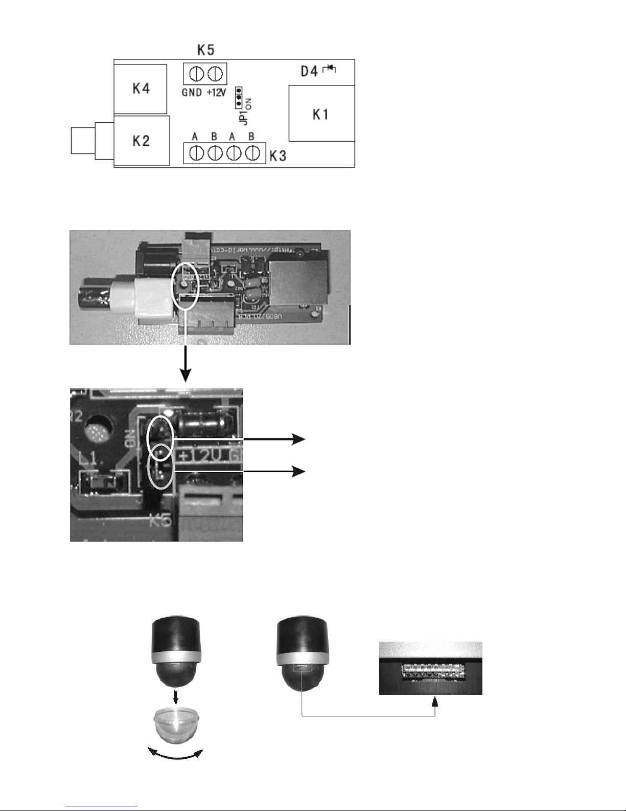
K1: RJ45 terminal jack
K2: BNC jack
K3: RS485 input and output terminal block
K4: 12VDC input terminal block
K5: 12VDC input terminal block
JP1: RS485 resistor
D4: indicator light
Note: K3 and K4 are two different power inputs with different PIN configuration.
b. RS485 Resistor
Always place the RS485 resistor of the last
camera in the series on ON in order to prevent
reflection and disturbance of the RS485
communication with other devices.
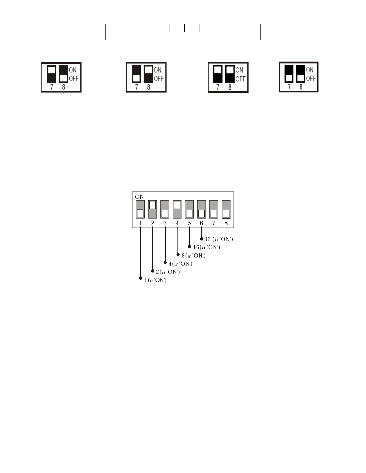
5. Protocol Setup
DIP switches 7 and 8 define the camera protocol. Please, refer to the figure below to set the Pelco-P or the Pelco-D
protocol.
ON
Factory Default Setting OFF
Page 3
CAMCOLD3 - 3 - VELLEMAN
DIP switch 1 2 3 4 5 6 7 8
Camera ID Protocol
DIP Switch Setting:
Press F4 on the controller and select the same protocol as the one on the camera.
6. Camera ID Setup
Set the binary number for the camera ID by changing the DIP switch (0 = OFF, 1 = ON).
Example: Setting the camera ID as 10 (ID = 0 + 2 + 0 + 8 + 0 = 10).
• You can set the camera ID from 0 to 63. Do not use the value 0 as ID.
• The default camera ID is 1.
• If you desire operating the camera with a controller, the camera ID setting and the controller ID must be identical.
When using more than one camera, it is recommended to memorize the camera IDs and their camera locations.
• Camera ID under Pelco-D = camera ID under Pelco-P/Vicanyx -1. Camera ID 2 under Pelco-D = camera ID under
Pelco-P/Vicanyx.
7. Installation
• A qualified technician should install and service this device according to the local regulation.
• Do not leave fingerprints on the lens as they will affect the picture quality. Clean the lens with a soft cloth. Do not
use alcohol or solvents.
• The auto scan range can be adjusted by the controlling software. The dome does not have any limit stop bolts.
Tilt limit is not adjustable; do not try to make any adjustments by hand.
Pelco
-
D protocol
Pelco
-P Protocol
Pelco
-
P protocol
Vicanyx protocol
Baud rate: 2400bps Baud rate: 9600bps Baud rate: 9600bps
Non-continuous code continuous code
Page 4
CAMCOLD3 - 4 - VELLEMAN
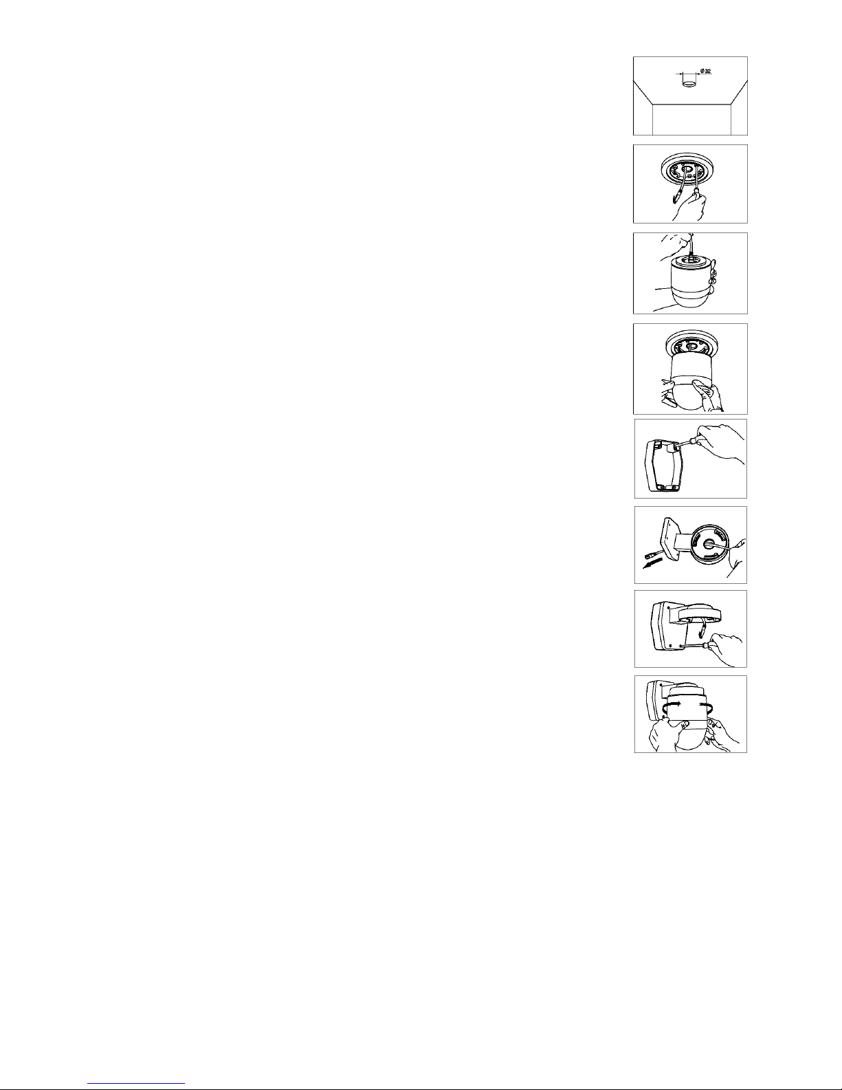
a. Ceiling Mounting
1. Choose a mounting location. Drill a Ø30mm hole for the cabling in the ceiling using an
appropriate hole saw. If the ceiling isn’t firm enough, install a suitable board to strengthen.
Now, install the mounting bracket for dome cameras (CAMCOLD/CB2).
2. Connect the 8-core twisted pair to the RS485 adapter and slide it through the hole in the
ceiling. Connect the other end of the cable to the dome camera. For the correct wiring of
the RS485 adapter, refer to “Connection”.
3. Place the dome onto the mounting bracket. Align the three tabs on the dome camera with
the three slots on the mounting bracket. Push and turn the camera in a clockwise direction
until it locks in place.
b. Wall Mounting
REMARK: To avoid vibrating pictures, make sure the construction to which the device is
attached is able to support 5 times the weight of the camera and the bracket.
1. Fix the bracket support to the wall with the screws included with the bracket.
2. Open the back of the wall bracket (CAMCOLD/B1) and slide the cable through the hole.
3. Connect the cable to the RS485 adapter. Mount the wall bracket onto the wall and fix it
using the screws included with the wall bracket.
4. Connect the twisted pair to the dome camera. Place the camera onto the wall bracket.
Align the three tabs on the camera with the three slots of the bracket. Push and turn the
camera in a clockwise direction until it locks in place.
8. Controlling the Dome Camera
a. Selecting the Camera
• Choose a camera by pressing the camera number 1 – 99 and the CAM key.
• Press -1 to choose the previous camera or press +1 to choose the next camera.
Example: Selecting camera n° 2.
o Press 2 and the CAM key to select camera n° 2.
o After having selected the camera, press -1 to select the previous camera or press +1 to select the next
camera.
b. Controlling the P/T and the Lens
• Select a camera (see “Selecting a Camera”).
• Press Z-, Z+, F- or F+ to control the P/T or tilt the joystick to control the lens.
Page 5

CAMCOLD3 - 5 - VELLEMAN
Example: Controlling the P/T of camera n° 2.
o Press 2 and the CAM key to select camera n° 2.
o Tilt the joystick to control the camera P/T or use the Z-, Z+, F- or F+ key to control the lens.
c. Setting Up the Preset
• Select a camera and set the P/T and the lens to the desired position.
• Press the F1 key and press 8.
• Define the preset number (1 – 64).
• Press PRE to confirm.
Example: Setting preset 15 to camera n° 5.
o Press 5 and then press the CAM key to select the camera.
o Move the P/T and the lens to the desired position.
o Press the F1 key.
o Press 8.
o Press 15.
o Press PRE to confirm your selection.
d. Running the Preset
• Select the desired camera number.
• Define the preset (1 - 64). The default preset is 1.
• Press the CALL key. The corresponding preset will be displayed on the screen.
Example: Setting camera n° 3 to preset 6.
o Press 3.
o Press the CAM key.
o Press 6.
o Press the CALL key.
o Preset 6 of camera n° will be displayed.
e. Pausing a Running Preset
• Select the desired camera ID (1 – 63).
• Press the HOLD key or tilt the joystick. The auto running preset will be paused.
Example: Pausing the preset of camera n° 4.
o Press 4.
o Press the CAM key.
o Press HOLD or tilt the joystick. The preset of camera 4 will be paused.
f. Setting the Auto Scan
• Make the camera turn to the left using the joystick until the desired position has been reached.
• Press 92 and press the CALL key to set the left limit auto scan.
• Make the camera turn to the right using the joystick until the desired position has been reached.
• Press 93 and press the CALL key to set the right limit auto scan.
• Press the PAN key to make the camera scan from the left to the right. When the camera reaches the appointed
position, it will pause for 2 seconds and then move repeatedly from the left to the right. To stop the auto scan, just
tilt the joystick.
Page 6

CAMCOLD3 - 6 - VELLEMAN
Example: Setting the auto scan for camera n° 2.
o Press 2 and then the CAM key to select the camera.
o Make the camera turn to the left using the joystick until the desired position has been reached.
o Press 92 and press the CALL key to set the left limit auto scan.
o Make the camera turn to the right using the joystick until the desired position has been reached.
o Press 93 and press the CALL key to set the right limit auto scan.
o Press the PAN key to confirm your settings. Camera n° 2 will auto scan within the predefined range.
9. Troubleshooting
Problem Possible Cause Solution
Wrong connection. Check the connection. The camera does not react when
connected to a power supply.
Power deficiency. Check the power supply.
Wrong camera ID or baud rate. Reset the camera ID or baud rate.
Wrong protocol. Reset the protocol.
Light and image cannot be
controlled.
Wrong RS485 terminator setting. Reset the RS485 terminator setting.
Non-compatible protocol. Reset the DIP setting.
Wrong camera ID. Reset the camera ID.
Power deficiency. Check the power supply.
The camera cannot be controlled or
is moving erratically.
Wrong RS485 terminator setting. Reset the RS485 terminator setting.
Wrong zoom setting. Reset the zoom setting.
Fluctuating image.
Power deficiency. Check the power supply.
Focus is manually set. Run a preset or set the camera.
Dimmed image.
Dirty lens. Clean the lens.
10. Technical Specifications
Camera
System PAL/NTSC
Sensor 1/4” SONY Super HAD CCD
Pixels 512 (H) x 492 (V)
Horizontal Resolution 420 TV lines
S/N Ratio ≥ 48dB
Zoom 22x optical zoom (f = 3.9 – 85.8mm); 10x digital zoom
Min. Illumination 0.5 lux / F1.4
Iris auto / manual
Focus auto / manual
White Balance auto / manual
Backlight auto
Video Output Level 1.0Vpp / 75Ω composite
Synchronizing System internal
Gamma Correction 0.45
AGC max. 29dB
Electronic Shutter Control auto (1/50 – 1/100000sec) / flickerless mode
Pan/Tilt
Swing Angle pan: 360° continuous rotation; tilt: 90°
Swing Speed pan: 0.5°/s ~ 45°/s; tilt: 0.5°/s ~ 45°/s
Presets 64
Communication RS485
Baud Rate 9600 bit/s
Protocol Pelco-P, Pelco-D
Housing ABS cast plastic
Page 7

CAMCOLD3 - 7 - VELLEMAN
Others
Power Supply 12VDC / 2A
Power Consumption 15W
Dimensions Ø126 x 185mm (dome: Ø130mm)
Weight 1.5kg
Operation Temperature 0°C – 50°C
Options
Housings CAMCOLD/HB, CAMCOLD/B1, CAMCOLD/CB
Controller Keyboard via RS485 CAMCOLC/CK
Brackets CAMCOLD/B2, CAMCOLD/CB1
11. Connection Example
The information in this manual is subject to change without prior notice.
Page 8
CAMCOLD3 - 8 - VELLEMAN
CAMCOLD3 – KLEUREN DOME CAMERA – 22x ZOOM
1. Inleiding
Aan alle ingezetenen van de Europese Unie
Belangrijke milieu-informatie betreffende dit product
Dit symbool op het toestel of de verpakking geeft aan dat, als het na zijn levenscyclus wordt weggeworpen,
dit toestel schade kan toebrengen aan het milieu.
Gooi dit toestel (en eventuele batterijen) niet bij het gewone huishoudelijke afval; het moet bij een
gespecialiseerd bedrijf terechtkomen voor recyclage.
U moet dit toestel naar uw verdeler of naar een lokaal recyclagepunt brengen.
Respecteer de plaatselijke milieuwetgeving.
Hebt u vragen, contacteer dan de plaatselijke autoriteiten inzake verwijdering.
Dank u voor uw aankoop! Lees deze handleiding grondig voor u het toestel in gebruik neemt. Werd het toestel
beschadigd tijdens het transport, installeer het dan niet en raadpleeg uw dealer.
2. Safety Instructions
• De garantie geldt niet voor schade door het negeren van bepaalde richtlijnen in deze handleiding en uw dealer zal
de verantwoordelijkheid afwijzen voor defecten of problemen die hier rechtstreeks verband mee houden.
• Laat dit toestel installeren en onderhouden door een geschoolde technicus.
• Schade door wijzigingen die de gebruiker heeft aangebracht aan het toestel vallen niet onder de garantie.
• Houd dit toestel uit de buurt van kinderen en onbevoegden.
3. Algemene richtlijnen
• Gebruik enkel een voeding van 12VDC om beschadiging van de camera te vermijden.
• Plaats of monteer dit toestel niet op een onstabiele voet, driepoot of montagebeugel om beschadiging te
vermijden.
• Stel de camera niet bloot aan direct zonlicht, vochtigheid of bijtende gassen.
• Schud het toestel niet dooreen. Vermijd brute kracht tijdens de installatie en de bediening van dit toestel.
• Om veiligheidsredenen mag de gebruiker geen wijzigingen aanbrengen aan het toestel.
• Ontkoppel het toestel van het lichtnet voor u aan onderhoudswerkzaamheden begint.
• Maak het toestel geregeld schoon met een vochtige, niet pluizende doek. Gebruik geen alcohol of solvent.
• De gebruiker mag geen onderdelen vervangen.
• Bestel eventuele reserveonderdelen bij uw dealer.
4. Aansluiting
a. Aansluiting van de externe kabels
Alle camera’s worden op een RS485-adapter aangesloten. Gebruik een 8-aderige twisted pair-kabel van 0.5mm om
de camera op de RS485-adapter aan te sluiten. De RJ45, een doorschijnende aansluiting op beide zijden van de
kabel, sluit u aan op de RS485-adapter en de RJ45-aansluiting van de camera.
Wees voorzichtig bij de installatie: raak geen kabels aan die onder stroom staan om
dodelijke
elektroshocks te vermijden.
Bescherm dit toestel tegen regen en vochtigheid.
Verzeker u ervan dat het toestel niet aangesloten is op een stroombron alvorens het te openen.
Open de behuizing niet; mogelijke elektroshocks.
Page 9

CAMCOLD3 - 9 - VELLEMAN
K1: RJ45-aansluiting
K2: BNC jackaansluiting
K3: RS485 in- en uitgangsblok
K4: 12VDC ingangsblok
K5: 12VDC ingangsblok
JP1: RS485-weerstand
D4: indicatielampje
Opmerking: K3 en K4 zijn twee verschillende voedingsingangen met een afwijkende pinconfiguratie.
b. RS485-weerstand
Plaats de RS485-weerstand van de laatste
camera in de serie op ON zodat storingen van
de communicatie tussen de RS485 en andere
apparaten worden tegengegaan.
5. Het protocol instellen
DIP-schakelaars 7 en 8 definiëren het protocol van de camera. Raadpleeg de onderstaande figuur en stel het PelcoP of Pelco-D protocol in.
ON
OFF (fabrieksinstelling)
Page 10

CAMCOLD3 - 10 - VELLEMAN
DIP-
schakelaar
1 2 3 4 5 6 7 8
Camera-ID Protocol
Instelling van de DIP-schakelaars:
Druk op F4 op het bedieningspaneel en kies hetzelfde protocol als dat van de camera.
6. Instellen van de camera-ID
Stel het binaire nummer in voor de camera-ID aan de hand van de
DIP-schakelaars (0 = OFF, 1 = ON).
Voorbeeld: ID van de camera 10 (ID = 0 + 2 + 0 + 8 + 0 = 10).
• De camera-ID is instelbaar van 1 tot 63. Gebruik waarde 0 niet als ID.
• De standaard camera-ID is 1.
• Wenst u de camera aan de hand van een controller te besturen, zorg dan dat de ID van de controller en deze van
de camera identiek zijn. Wanneer u meer dan één camera gebruikt, raden wij u aan de IDs en de locatie van elke
camera te noteren.
• Camera-ID onder Pelco-D = camera-ID onder Pelco-P/Vicanyx -1. Camera-ID 2 onder Pelco-D = camera-ID
onder Pelco-P/Vicanyx.
7. Installatie
Zie Engelse handleiding vanaf pagina 4.
8. De camera besturen
Zie Engelse handleiding vanaf pagina 4.
Pelco
-
D protocol
Pelco
-P Protocol
Pelco
-
P protocol
Vicanyx protocol
Snelheid: 2400bps Snelheid: 9600bps Snelheid: 9600bps
Niet-continue code Continue code
Page 11

CAMCOLD3 - 11 - VELLEMAN
9. Problemen en oplossingen
Probleem Mogelijke oorzaak Oplossing
Verkeerde aansluiting. Controleer de aansluiting. De camera reageert niet wanneer u
de voeding aansluit.
Geen voeding. Controleer de voeding.
Verkeerde camera-ID of
overdrachtsnelheid.
Stel de camera-ID of
overdrachtsnelheid opnieuw in.
Verkeerd protocol. Stel het protocol opnieuw in.
De lichtsterkte en het beeld kunnen
niet worden bijgeregeld.
Verkeerde instelling van de RS485weerstand.
Stel de RS485-weerstand opnieuw
in.
Niet-compatibel protocol. Stel de DIP-schakelaars opnieuw in.
Verkeerde camera-ID. Stel de camera-ID opnieuw in.
Geen voeding. Controleer de voeding.
De camera kan niet worden bestuurd
/ onregelmatige beweging.
Verkeerde instelling van de RS485weerstand.
Stel de RS485-weerstand opnieuw
in.
Verkeerde zoominstelling. Stel de zoominstelling opnieuw in.
Onstabiel beeld.
Geen voeding. Controleer de voeding.
Focussering is manueel ingesteld. Laat een voorprogramma lopen of
stel de camera in.
Donker beeld.
Bevuilde lens. Maak de lens schoon.
10. Technische specificaties
Camera
Systeem PAL/NTSC
Sensor 1/4” SONY Super HAD CCD
Pixels 512 (H) x 492 (V)
Horizontale resolutie 420 tv-lijnen
S/R verhouding ≥ 48dB
Zoom 22x optische zoom (f = 3.9 – 85.8mm); 10x digitale zoom
Lichtsterkte 0.5 lux / F1.4
Iris auto / manueel
Focus auto / manueel
Witbalans auto / manueel
Backlight auto
Video-uitgang 1.0Vpp / 75Ω composiet
Sync System intern
Gammacorrectie 0.45
AGC max. 29dB
Elektronische sluiter auto (1/50 – 1/100000sec.) / flickerless mode
Pan/Tilt
Hoek pan: 360° continue rotatie; tilt: 90°
Snelheid pan: 0.5°/sec. ~ 45°/sec.; tilt: 0.5°/sec. ~ 45°/sec.
Presets 64
Communicatie RS485
Overdrachtsnelheid 9600 bit/sec.
Protocol Pelco-P, Pelco-D
Behuizing ABS gegoten plastic
Andere
Voeding 12VDC / 2A
Verbruik 15W
Afmetingen Ø126 x 185mm (dome: Ø130mm)
Gewicht 1.5kg
Werktemperatuur 0°C – 50°C
Page 12

CAMCOLD3 - 12 - VELLEMAN
Opties
Behuizingen CAMCOLD/HB, CAMCOLD/B1, CAMCOLD/CB
Bedieningspaneel via RS485 CAMCOLC/CK
Montagebeugels CAMCOLD/B2, CAMCOLD/CB1
11. Aansluitingsvoorbeeld
Zie figuur pagina 7.
De informatie in deze handleiding kan te allen tijde worden gewijzigd zonder voorafgaande kennisgeving.
CAMCOLD3 – CAMÉRA DÔME COULEUR– 22x ZOOM
1. Introduction
Aux résidents de l'Union européenne
Des informations environnementales importantes concernant ce produit
Ce symbole sur l'appareil ou l'emballage indique que l’élimination d’un appareil en fin de vie peut polluer
l'environnement.
Ne pas éliminer un appareil électrique ou électronique (et des piles éventuelles) parmi les déchets
municipaux non sujets au tri sélectif ; une déchetterie traitera l’appareil en question.
Renvoyer les équipements usagés à votre fournisseur ou à un service de recyclage local.
Il convient de respecter la réglementation locale relative à la protection de l’environnement.
Si vous avez des questions, contactez les autorités locales pour élimination.
Nous vous remercions de votre achat ! Lisez attentivement la présente notice avant la mise en service de l'appareil.
Si l’appareil a été endommagé pendant le transport, ne l'installez pas et consultez votre revendeur.
2. Prescriptions de sécurité
• La garantie ne s'applique pas aux dommages survenus en négligeant certaines directives de cette notice et votre
revendeur déclinera toute responsabilité pour les problèmes et les défauts qui en résultent.
• Confiez l'installation et l’entretien à un personnel qualifié.
• Les dommages occasionnés par des modifications à l'appareil par le client, ne tombent pas sous la garantie.
• Gardez votre CAMCOLD3 hors de la portée de personnes non qualifiées et de jeunes enfants.
3. Directives générales
• N’utilisez qu’une alimentation de 12VCC pour éviter d‘endommager la caméra.
• Pour éviter des endommagements, ne placez ou ne montez pas la caméra sur un socle, trépied ou support de
montage instable.
• Évitez d‘exposer la caméra aux rayons directs du soleil, à l’humidité ou à des gaz caustiques.
• Évitez de secouer l'appareil et traitez l'appareil avec circonspection pendant l'installation et l'opération.
N’ouvrez pas le boîtier ; risques d’électrochocs.
Soyez prudent lors de l'installation : toucher un câble sous tension peut causer des électrochocs mortels.
Protégez l'appareil contre la pluie et l'humidité.
Débranchez le câble d'alimentation avant d'ouvrir le boîtier.
Page 13

CAMCOLD3 - 13 - VELLEMAN
• Toute modification de l’appareil est interdite pour des raisons de sécurité.
• Débranchez l'appareil avant de le nettoyer.
• Essuyez l'appareil régulièrement avec un chiffon humide non pelucheux. Evitez l'usage d'alcool et de solvants.
• Il n’y a aucune pièce maintenable par l’utilisateur.
• Commandez des pièces de rechange éventuelles chez votre revendeur.
4. Connexion
a. Connexion du câble externe
Toutes les caméras seront connectées à un adaptateur RS485. Utilisez une paire torsadée de 0.5mm à 8
conducteurs pour la connexion de la caméra dôme à l’adaptateur RS485. Fixez un connecteur type RJ45 à chaque
extrémité de la paire torsadée et insérez un connecteur dans l’adaptateur RS485 et l’autre dans l’entrée RJ45 de la
caméra dôme.
K1: Connecteur RJ45
K2: Connecteur BNC
K3: Bloc de bornes d’entrée et de sortie RS485
K4: Bloc d’entrée 12VCC
K5: Bloc d’entrée 12VCC
JP1: Résistance RS485
D4: Voyant
Remarque: K3 et K4 sont deux entrées d’alimentation différentes avec une configuration différentes des bornes.
b. Résistance RS485
Placez la résistance RS485 de la dernière caméra dans la
série sur ON pour éviter les brouillages de la
communication entre le RS485 et les autres appareils.
ON
OFF (réglage par défaut)
Page 14

CAMCOLD3 - 14 - VELLEMAN
5. Instauration du protocole
Les commutateurs DIP n° 7 et 8 déterminent le protocole de la caméra. Consultez l’illustration ci-dessous et
choisissez entre le protocole Pelco-P ou le protocole Pelco-D.
DIP 1 2 3 4 5 6 7 8
ID de la caméra Protocole
Réglage des commutateurs DIP :
Enfoncez F4 sur la console de commande et sélectionnez le même protocole que celui de la caméra.
6. Instauration de l’ID de la caméra
Établissez le nombre binaire de l’ID de la caméra en modifiant les
commutateurs DIP (0 = OFF, 1 = ON).
Exemple: Établir l’ID de la caméra comme 10 (ID = 0 + 2 + 0 + 8 + 0 =
10).
• Choisissez un numéro d’ID de caméra de 1 à 63. N’utilisez pas la valeur 0.
• L’ID par défaut est la valeur 1.
• Si vous désirez contrôler la caméra à l’aide d’une console de contrôle, veillez à ce que l’ID de la caméra et de la
console soient identiques. Si vous utilisez plusieurs caméras, il est conseillé de noter les IDs et la localisation de
chaque caméra.
• ID de la caméra sous Pelco-D = Id de la caméra sous Pelco-P/Vicanyx -1. ID de la caméra 2 sous Pelco-D = ID
de la caméra sous Pelco-P/Vicanyx.
Protocole Pelco
-D
Protocole Pelco
-P
Protocole Pelco
-P
Protocole Vicanyx
Vitesse : 2400bps Vitesse : 9600bps Vitesse : 9600bps
Code non continu Code continu
Page 15

CAMCOLD3 - 15 - VELLEMAN
7. Installation
Voir notice en Anglais à la page 4.
8. Contrôle de la caméra dôme
Voir notice en Anglais à la page 4.
9. Solutions aux problèmes
Problème Cause possible Solution
Connexion incorrecte. Vérifiez la connexion. La caméra ne réagit pas lors d la
connexion de l’alimentation.
Alimentation défaillante. Vérifiez l’alimentation.
ID de la caméra ou vitesse de
transmission incorrecte.
Réinstaurez l’ID de la caméra ou la
vitesse de transmission.
Protocole incorrecte. Réinstaurez le protocole.
L’intensité lumineuse et l’image ne
peuvent pas être contrôlées.
Réglage de la résistance RS485
incorrect.
Réinstaurez la résistance RS485.
Protocole incompatible. Réinstaurez les commutateurs DIP.
ID de la caméra incorrecte. Réinstaurez l’ID de la caméra.
Alimentation défaillante. Vérifiez l’alimentation.
La caméra est incontrôlable /
mouvement irrégulier.
Réglage de la résistance RS485
incorrect.
Réinstaurez la résistance RS485.
Réglage du zoom incorrect. Réglez le zoom.
Image instable.
Alimentation défaillante. Vérifiez l’alimentation.
Focalisation réglée manuellement. Démarrez une présélection ou réglez
la focalisation. Image floue.
Objectif sale. Nettoyez l’objectif.
10. Spécifications techniques
Caméra
Système PAL/NTSC
Capteur 1/4” SONY Super HAD CCD
Pixels 512 (H) x 492 (V)
Résolution horizontale 420 lignes TV
Rapport S/B ≥ 48dB
Zoom 22x zoom optique (f = 3.9 – 85.8mm); 10x zoom numérique
Intensité lumineuse 0.5 lux / F1.4
Iris auto / manuel
Focalisation auto / manuel
Balance des blancs auto / manuel
« Backlight » auto
Sortie vidéo 1.0Vpp / 75Ω composite
Sync System interne
Correction gamma 0.45
AGC max. 29dB
Obturateur électronique auto (1/50 – 1/100000sec) / mode « flickerless »
Pan/Tilt
Angle pan : 360° rotation continue ; tilt : 90°
Vitesse pan : 0.5°/sec ~ 45°/sec ; tilt : 0.5°/sec ~ 45°/sec
Présélections 64
Communication RS485
Vitesse de transmission 9600 bit/sec
Page 16

CAMCOLD3 - 16 - VELLEMAN
Protocole Pelco-P, Pelco-D
Boîtier résine ABS
Autres
Alimentation 12VDC / 2A
Consommation 15W
Dimensions Ø126 x 185mm (dôme : Ø130mm)
Poids 1.5kg
Température de service 0°C – 50°C
Options
Boîtiers CAMCOLD/HB, CAMCOLD/B1, CAMCOLD/CB
Console de commande via RS485 CAMCOLC/CK
Supports de montage CAMCOLD/B2, CAMCOLD/CB1
11. Exemple d’une connexion
Voir notice en Anglais à la page 7.
Toutes les informations présentées dans cette notice peuvent être modifiées sans notification préalable.
CAMCOLD3 – CÁMARA DOMO COLOR – 22x ZOOM
1. Introducción
A los ciudadanos de la Unión Europea
Importantes informaciones sobre el medio ambiente concerniente a este producto
Este símbolo en este aparato o el embalaje indica que, si tira las muestras inservibles, podrían dañar el
medio ambiente.
No tire este aparato (ni las pilas, si las hubiera) en la basura doméstica; debe ir a una empresa
especializada en reciclaje. Devuelva este aparato a su distribuidor o a la unidad de reciclaje local.
Respete las leyes locales en relación con el medio ambiente.
Si tiene dudas, contacte con las autoridades locales para residuos.
¡Gracias por haber comprado la CAMCOLD3! Lea atentamente las instrucciones del manual antes de usarla. Si el
aparato ha sufrido algún daño en el transporte no lo conecte a la red y póngase en contacto con su distribuidor.
2. Instrucciones de seguridad
• Daños causados por descuido de las instrucciones de seguridad de este manual invalidarán su garantía y su
distribuidor no será responsable de ningún daño u otros problemas resultantes.
• La instalación y el mantenimiento deben ser realizados por personal especializado.
• Los daños causados por modificaciones no autorizadas, no están cubiertos por la garantía.
• Mantenga la CAMCOLD3 lejos del alcance de personas no capacitadas y niños.
No abra la caja; riesgos de electrochoque.
Cuidado durante la instala
ción: puede sufrir una peligrosa descarga eléctrica al tocar los cables con un
voltaje peligroso.
No exponga este equipo a lluvia
ni
humedad
.
Desconecte el cable de alimentación de la red antes de abrir la caja
.
Page 17

CAMCOLD3 - 17 - VELLEMAN
3. Normas generales
• Utilice sólo una alimentación de 12VCC para evitar dañar la cámara.
• Para evitar daños, no ponga ni monte la cámara en un pie, trípode o soporte de montaje inestable.
• No exponga la cámara a la luz solar directa, humedad o gases cáusticos.
• No agite el aparato. Evite usar excesiva fuerza durante la instalación y la reparación.
• Por razones de seguridad, las modificaciones no autorizadas del aparato están prohibidas.
• Desconecte siempre el aparato de la red antes de limpiarlo.
• Limpie el aparato regularmente con un paño húmedo y sin pelusas. Evite el uso de alcohol y de disolventes.
• El usuario no habrá de efectuar el mantenimiento de ninguna pieza.
• Contacte con su distribuidor si necesita piezas de recambio.
4. Conexión
a. Conectar el cable externo
Todas las cámaras están conectadas a un adaptador RS485. Utilice un cable de 8 polos y par trenzado de 0.5mm
para conectar la cámara domo al adaptador RS485. Fije un conector del tipo RJ45 a cada extremo del par trenzado
e introduzca un conector en el adaptador RS485 y el otro en la entrada RJ45 de la cámara domo.
K1: Conector RJ45
K2: Conector BNC
K3: Bloque de bornes de entrada y salida RS485
K4: Bloque de entrada 12VCC
K5: Bloque de entrada 12VCC
JP1: Resistencia RS485
D4: Indicador
Observación: K3 y K4 son dos entradas de alimentación diferentes con otra configuración de los polos.
b. Resistencia RS485
Ponga la resistencia RS485 de la última cámara de la serie
en la posición ON para evitar interferencias en la
comunicación entre el RS485 y los otros aparatos.
ON
OFF (ajuste de fábrica)
Page 18

CAMCOLD3 - 18 - VELLEMAN
5. Seleccionar el protocolo
Los conmutadores DIP n° 7 y 8 determinan el protocolo de la cámara. Véase la siguiente figura y seleccione entre el
protocolo Pelco-P y el protocolo Pelco-D.
DIP 1 2 3 4 5 6 7 8
ID de la cámara Protocolo
Ajuste de los conmutadores DIP:
Pulse F4 en la consola de control y seleccione el mismo protocolo que el de la cámara.
6. Seleccionar ID de la cámara
Introduzca el número binario de ID de la cámara con los
conmutadores DIP (0 = OFF, 1 = ON).
Ejemplo: introduzca ID de la cámara como 10 (ID = 0 + 2 + 0 + 8 + 0
= 10).
• Seleccione un número de ID de cámara de 1 a 63. No utilice el valor 0.
• ID por defecto es el valor 1.
• Si quiere controlar la cámara con una consola de control, asegúrese de que el ID de la cámara y de la consola
sea idéntico. Si utiliza varias cámaras, apunte ID y la localización de cada cámara.
• ID de la cámara en Pelco-D = Id de la cámara en Pelco-P/Vicanyx -1. ID de la cámara 2 en Pelco-D = ID de la
cámara en Pelco-P/Vicanyx
Protocolo
Pelco
-D
Protocolo Pelco
-P
Protocolo Pelco
-P
Protocolo Vicanyx
Velocidad: 2400bps Velocidad: 9600bps Velocidad: 9600bps
Código no continuo Código continuo
Page 19

CAMCOLD3 - 19 - VELLEMAN
7. Instalación
Véase en la página 3.
8. Manejar la cámara domo
Véase en la página 4.
9. Solución de problemas
Problema Causa posible Solución
Conexión incorrecta. Verifique la conexión. La cámara no reacciona al conectar
la alimentación.
Alimentación defectuosa. Verifique la alimentación.
ID de la cámara o velocidad de
transmisión incorrecta.
Vuelva a seleccionar ID de la
cámara o la velocidad de
transmisión.
Protocolo incorrecto. Vuelva a seleccionar el protocolo.
Es imposible controlar la intensidad
luminosa y la imagen.
Ajuste incorrecto de la resistencia
RS485.
Vuelva a seleccionar la resistencia
RS485.
Protocolo incompatible. Vuelva a seleccionar los
conmutadores DIP.
ID incorrecto de la cámara. Vuelva a seleccionar ID de la
cámara.
Alimentación defectuosa. Verifique la alimentación.
Es imposible controlar la cámara /
movimiento irregular.
Ajuste incorrecto de la resistencia
RS485.
Vuelva a seleccionar la resistencia
RS485.
Ajuste incorrecto del zoom. Ajuste el zoom.
Imagen inestable.
Alimentación defectuosa. Verifique la alimentación.
Foco ajustado manualmente. Ejecute una preselección o ajuste el
foco.
Imagen oscura.
Óptica sucia. Limpie la óptica.
10. Especificaciones
Cámara
Sistema PAL/NTSC
Sensor de imágenes SONY Super HAD CCD de 1/4”
Píxeles 512 (H) x 492 (V)
Resolución horizontal 420 líneas TV
Relación señal/ruido ≥ 48dB
Zoom 22x zoom óptico (f = 3.9 – 85.8mm); 10x zoom digital
Intensidad luminosa 0.5 lux / F1.4
Iris automático / manual
Foco automático / manual
Balance de los blancos automático / manual
Retroiluminación automática
Salida de vídeo 1.0Vpp / 75Ω compuesto
Sincronización interna
Corrección de contraste (gama) 0.45
AGC máx. 29dB
Shutter electrónico automático (1/50 – 1/100000seg.) / modo « flickerless »
Pan/Tilt
Ángulo pan : 360° rotación continua ; tilt : 90°
Velocidad pan : 0.5°/seg. ~ 45°/seg. ; tilt : 0.5°/seg. ~ 45°/seg.
Page 20

CAMCOLD3 - 20 - VELLEMAN
Preselecciones 64
Comunicación RS485
Velocidad de transmisión 9600 bit/seg.
Protocolo Pelco-P, Pelco-D
Carcasa resina ABS
Otras Especificaciones
Alimentación 12VDC / 2A
Consumo 15W
Dimensiones Ø126 x 185mm (domo: Ø130mm)
Peso 1.5kg
Temperatura de funcionamiento 0°C – 50°C
Opciones
Carcasas CAMCOLD/HB, CAMCOLD/B1, CAMCOLD/CB
Consola de control por RS485 CAMCOLC/CK
Soportes de montaje CAMCOLD/B2, CAMCOLD/CB1
11. Ejemplo de una conexión
Véase en la página 7.
Se pueden modificar las especificaciones y el contenido de este manual sin previo aviso.
CAMCOLD3 – DOME-FARBKAMERA – 22 x ZOOM
1. Einführung
An alle Einwohner der Europäischen Union
Wichtige Umweltinformationen über dieses Produkt
Dieses Symbol auf dem Produkt oder der Verpackung zeigt an, dass die Entsorgung dieses Produktes nach
seinem Lebenszyklus der Umwelt Schaden zufügen kann.
Entsorgen Sie die Einheit (oder verwendeten Batterien) nicht als unsortiertes Hausmüll; die Einheit oder
verwendeten Batterien müssen von einer spezialisierten Firma zwecks Recycling entsorgt werden.
Diese Einheit muss an den Händler oder ein örtliches Recycling-Unternehmen retourniert werden.
Respektieren Sie die örtlichen Umweltvorschriften.
Falls Zweifel bestehen, wenden Sie sich für Entsorgungsrichtlinien an Ihre örtliche Behörde.
Danke für Ihren Ankauf! Lesen Sie diese Bedienungsanleitung vor Inbetriebnahme sorgfältig durch. Überprüfen Sie,
ob Transportschäden vorliegen. Sollte dies der Fall sein, verwenden Sie das Gerät nicht.
2. Sicherheitsvorschriften
• Bei Schäden, die durch Nichtbeachtung der Bedienungsanleitung verursacht werden, erlischt der
Garantieanspruch. Für daraus resultierende Folgeschäden übernimmt der Hersteller keine Haftung.
• Das Gerät muss von einem Fachmann installiert und gewertet werden.
• Bei Schäden, verursacht durch eigenmächtige Änderungen, erlischt der Garantieanspruch.
• Halten Sie Kinder und Unbefugte vom Gerät fern.
Seien Sie vorsichtig bei der In
stallation: Fassen Sie die unter Strom stehenden Kabel nicht an, um
einen lebensgefährlichen elektrischen Schlag zu vermeiden.
Das Gerät vor Regen und Feuchtigkeit schützen.
Trennen Sie das Gerät vor dem Öffnen vom Netz.
Öffnen Sie nie das Gehäuse. So vermeiden Sie elektrische Schläge.
Page 21

CAMCOLD3 - 21 - VELLEMAN
3. Allgemeine Richtlinien
• Verwenden Sie nur eine 12VDC-Stromversorgung um Beschädigung.
• Stellen Sie dieses Gerät nicht auf einen unstabilen Fuß, auf ein Stativ oder montieren Sie es nicht an einem
Montagebügel um Beschädigung zu vermeiden.
• Die Kamera keinem direkten Sonnenlicht, keiner Feuchtigkeit oder keinen beißenden Gasen aussetzen.
• Vermeiden Sie Erschütterungen und rohe Gewalt bei der Installation und Bedienung dieses Gerätes.
• Aus Sicherheitsgründen sind eigenmächtige Änderungen verboten.
• Trennen Sie das Gerät vor der Wartung vom Netz.
• Reinigen Sie das Gerät regelmäßig mit einem feuchten, flusenfreien Tuch. Verwenden Sie keinen Alkohol oder
keine Lösungsmittel.
• Der Benutzer darf nicht selbst Teile ersetzen.
• Wenden Sie sich für Ersatzteile an ihren Händler.
4. Anschluss
a. Anschluss der externen Kabel
Alle Kameras werden an einen RS485-Adapter angeschlossen. Verwenden Sie ein 8-adriges verdrilltes Kabel von
0.5mm um die Kamera an den RS485-Adapter anzuschließen. Der RJ45, ein transparenter Anschluss an beiden
Seiten des Kabels, schließen Sie an den RS485-Adapter und den RJ45-Anschluss der Kamera an.
K1: RJ45-Anschluss
K2: BNC-Anschluss
K3: RS485 Ein- und Ausgangsblock
K4: 12VDC Eingangsblock
K5: 12VDC Eingangsblock
JP1: RS485-Widerstand
D4: Anzeigelampe
Bemerkung: K3 und K4 sind zwei unterschiedliche Stromversorgungseingänge mit einer abweichenden Pinbelegung.
b. RS485-Widerstand
Stellen Sie den RS485-Widerstand der letzten Kamera in
der Reihe auf ON, sodass Störungen der Kommunikation
zwischen dem RS485 und anderen Geräten
entgegengetreten werden.
ON
OFF (Werkseinstelling)
Page 22

CAMCOLD3 - 22 - VELLEMAN
5. Protokoll einstellen
DIP-Schalter 7 und 8 definieren das Protokoll der Kamera. Siehe Abbildung unten und stellen Sie das Pelco-P oder
Pelco-D Protokoll ein.
DIP-Schalter 1 2 3 4 5 6 7 8
Kamera-ID Protokoll
Einstellung der DIP-Schalter :
Drücken Sie F4 im Steuergerät und wählen Sie dasselbe Protokoll als das der Kamera.
6. Einstellen der Kamera-ID
Stellen Sie die binäre Nummer für die Kamera-ID ein mithilfe der
DIP-Schalter (0 = OFF, 1 = ON).
Beispiel: ID der Kamera 10 (ID = 0 + 2 + 0 + 8 + 0 = 10).
• Die Kamera-ID ist von 1 bis 63 einstellbar. Verwenden Sie Wert 0 nicht als ID.
• Die standardmäßige Kamera-ID ist 1.
• Möchten Sie eine Kamera mit einem Steuergerät steuern, sorgen Sie dafür, dass die ID des Steuergerätes und
die der Kamera identisch sind. Wenn Sie mehr als eine Kamera verwenden, notieren Sie die IDs und Stelle jeder
Kamera.
• Kamera-ID unter Pelco-D= Kamera ID unter Pelco-P/Vicanyx-1. Kamera-ID 2 unter Pelco-D= Kamera-ID unter
Pelco-P/Vicanyx.
Pelco-
D Protokoll
Pelco
-P Protok
oll
Pelco
-P-
Protokoll
Vicanyx
-
Protokoll
Geschwindigkeit: 2400bps Geschwindigkeit: 9600bps Geschwindigkeit: 9600bps
nicht-kontinuierlicher Code kontinuierlicher Code
Page 23

CAMCOLD3 - 23 - VELLEMAN
7. Installation
Siehe englische Bedienungsanleitung ab Seite 4.
8. Kamera steuern
Siehe englische Bedienungsanleitung ab Seite 4.
9. Problemlösung
Problem mögliche Ursache Lösung
falscher Anschluss überprüfen Sie den Anschluss Die Kamera reagiert nicht wenn Sie
die Stromversorgung anschließen.
keine Stromversorgung überprüfen Sie die Stromversorgung
falsche Kamera-ID oder
Übertragungsgeschwindigkeit
Stellen Sie die Kamera-ID oder die
Übertragungsgeschwindigkeit erneut
ein.
falsches Protokoll stellen Sie das Protokoll erneut ein
Die Lichtstärke und das Bild können
nicht abgestimmt werden.
falsche Einstellung des RS485-
Widerstands
stellen Sie den RS485-Widerstand
erneut ein.
nicht-kompatibles Protokoll stellen Sie die DIP-Schalter erneut
ein.
falsche Kamera-ID Stellen Sie die Kamera-ID erneut ein
keine Stromversorgung Überprüfen Sie die
Stromversorgung.
Kamera kann nicht gesteuert werden
/ unregelmäßige Bewegung
falsche Einstellung des RS485-
Widerstands
stellen Sie den RS485-Widerstand
erneut ein.
falsche Zoomeinstellung stellen Sie die Zoomfunktion erneut
ein
Instabiles Bild
keine Stromversorgung Überprüfen Sie die Stromversorgung
Fokussierung ist manuell eingestellt Lassen Sie ein Vorprogramm
ablaufen oder stellen Sie die Kamera
ein
Dunkles Bild
schmutziges Objektiv reinigen Sie das Objektiv
10. Technische Daten
Kamera
System PAL/NTSC
Sensor 1/4” SONY Super HAD CCD
Pixel 512 (H) x 492 (V)
horizontale Auflösung 420 TV-Zeilen
Signal/Rauschabstand ≥ 48dB
Zoom 22x optisches Zoomobjektiv (f = 3.9 – 85.8mm); 10x digitales Zoom
Lichtstärke 0.5 lux / F1.4
Blende auto / manuell
Fokussierung auto / manuell
Weißabgleich auto / manuell
Hintergrundbeleuchtung auto
Video-Ausgang 1.0Vpp / 75Ω composite
Sync System intern
Gammakorrektur 0.45
AGC max. 29dB
elektronischer Verschluss auto (1/50 – 1/100000sec.) / flickerless Modus
Page 24

CAMCOLD3 - 24 - VELLEMAN
Schwenk/Neige
Winkel Schwenk: 360° ständige Rotation; Neige: 90°
Geschwindigkeit Schwenk: 0.5°/Sek. ~ 45°/Sek.; Neige: 0.5°/Sek. ~ 45°/Sek.
Voreinstellungen 64
Kommunikation RS485
Übertragungsgeschwindigkeit 9600 Bit/Sek.
Protokoll Pelco-P, Pelco-D
Gehäuse ABS-Kunststoff, gegossen
Andere
Stromversorgung 12VDC / 2A
Stromaufnahme 15W
Abmessungen Ø126 x 185mm (Dome: Ø130mm)
Gewicht 1.5kg
Betriebstemperatur 0°C – 50°C
Optionen
Gehäuse CAMCOLD/HB, CAMCOLD/B1, CAMCOLD/CB
Bedienfeld über RS485 CAMCOLC/CK
Montagebügel CAMCOLD/B2, CAMCOLD/CB1
11. Schaltplan
Siehe Abb. Seite 7.
Alle Änderungen vorbehalten.
 Loading...