


VVIP-2V, VVIP-3V, VVIP-5V
User Manual
CAUTION
RISK OF ELECTRIC SHOCK
DO NOT OPEN
CAUTION: TO REDUCE THE RISK OF ELECTRIC SHOCK DO NOT REMOVE COVER. NO USER SERVICABLE PARTS INSIDE.
REFER SERVICING TO QUALIFIED SERVICE PERSONNEL.
The lightning flash with arrowhead symbol, within an equilateral triangle, is intended to alert the user to the presence of un-insulated "dangerous voltage" within the product’s enclosure that may be of sufficient magnitude to constitute a risk of electric shock.
The exclamation point within an equilateral triangle is intended to alert the user to the presence of important operating and maintenance (servicing) instructions in the literature accompanying the appliance.
WARNING: TO PREVENT FIRE OR SHOCK HAZARD, DO NOT EXPOSE THIS UNIT TO RAIN OR MOISTURE.
CAUTION: TO PREVENT ELECTRIC SHOCK, MATCH WIDE BLADE OF THE PLUG TO THE WIDE SLOT AND FULLY INSERT.
www.veilux.net

Important Safeguards
In addition to the careful attention devoted to quality standards in the manufacturing process of your video product, safety is a major factor in the design of every instrument. However, safety is your responsibility too. This sheet lists important information that will help to assure your enjoyment and proper use of the video product and accessory equipment. Please read them carefully before operating and using your video product.
Installation
1.Read and Follow Instructions - All the safety and operating instructions should be read before the video product is operated. Follow all operating instructions.
2.Retain Instructions - The safety and operating instructions should be retained for future reference.
3.Heed Warnings - Comply with all warnings on the video product and in the operating instructions.
4.Polarization - Do not defeat the safety purpose of the polarized or grounding-type plug.
A polarized plug has two blades with one wider than the other. A grounding type plug has two
blades and a third grounding prong. The wide blade or the third prong are provided for your safety.
If the provided plug does not fit into your outlet, consult an electrician for replacement of the obsolete outlet.
5.Power Sources - This video product should be operated only from the type of power source indicated on the marking label. If you are not sure of the type of power supply to your location, consult your video dealer or local power company. For video products intended to operate from battery power, or other sources, refer to the operating instructions.
6.Overloading - Do not overload wall outlets of extension cords as this can result in the risk of fire or electric shock. Overloaded AC outlets, extension cords, frayed power cords, damaged or cracked wire insulation, and broken plugs are dangerous. They may result in a shock or fire hazard. Periodically examine the cord, and if its appearance indicates damage or deteriorated insulation, have it replaced by your service technician.
7.Power Cord Protection - Power supply cords should be routed so that they are not likely to be walked on or pinched byitems placed upon or against them, paying particular attention to cords at plugs, convenience receptacles, and the point where they exit from the video product.
8.Ventilation - Slots and openings in the caseare provided for ventilation to ensure reliable operation of the video product and to protect it from overheating. These openings must not be blocked or covered. The openings should never be blocked by placing the video equipment on a bed, sofa, rug, or other similar surface. This video product should never be placed near or over a radiator or heat register. This video product should not be placed in a built-in installation such as a bookcase or rack unless proper ventilation is provided or the video product manufacturer’s instructions have been followed.
9.Attachments - Do not use attachments unless recommended by the video product manufacturer as they may cause a hazard.
10.Camera Extension Cables – Check the rating of your extension cable(s) to verify compliance with your local authority regulations prior to installation.
11.Water and Moisture - Do not use this video product near water. For example, near a bath tub, wash bowl, kitchen sink or laundry tub, in a wet basement, near a swimming pool and the like.
Caution: Maintain electrical safety. Powerline operated equipment or accessories connected to this unit should bear the UL listing mark of CSA certification mark onthe accessory itself and should not be modified so as to defeat the safety features. This will help avoid any potential hazard from electrical shock or fire. If in doubt, contact qualified service personnel.
12.Accessories - Do not place this video equipment on an unstable cart, stand, tripod, or table. The video equipment may fall, causing serious damage to the video product. Usethis video product only with a cart, stand, tripod,
bracket, or table recommended by the manufacturer or sold with the video product. Any mounting of the product should follow the manufacturer’s instructions and use a mounting accessory recommended by the manufacturer.
Service
13.Servicing - Do not attempt to service this video equipment yourself as opening or removing covers may expose you to dangerous voltage or other hazards. Refer all servicing to qualified service personnel.
14.Conditions Requiring Service - Unplug this video product from the wall outlet and refer servicing to qualified service personnel under the following conditions:
•When the power supply cord or plug is damaged.
•If liquid has been spilled or objects have fallen into the video product.
•If the video product has been exposed to rain or water.
•If the video product does not operate normally by following the operating instructions. Adjust only those controls that are covered by the operating instructions. Improper adjustment ofother controls may result in damage and will often require extensive work by a qualified technician to restore the video product to its normal operation.
•If the video product has been dropped or the cabinet has been damaged.
•When the video product exhibits a distinct change in performance. This indicates a need for service.
15.Replacement Parts - When replacement parts are required, have the service technician verify that the replacements used have the same safety characteristics as the original parts. Use of replacements specified bythe video product manufacturer can prevent fire, electric shock or other hazards.
16.Safety Check - Upon completion of any service or repairs to this video product, ask the service technician to perform safety checks recommended by the manufacturer to determine that the video product is in safe operating condition.
17.Wall or Ceiling Mounting - The cameras provided should be mounted to a wall or ceiling only as instructed in this guide, using the provided mounting brackets.
18.Heat - The product should be situated away from heat sources such as radiators, heat registers, stoves, or other products (including amplifiers) that produce heat.
 Precautions
Use
19.Cleaning - Unplug the video product from the wall outlet before cleaning. Do not use liquid cleaners or aerosol cleaners. Use a damp cloth for cleaning.
20.Product and Cart Combination - Video and cart combination should be moved with care. Quick stops, excessive force, and uneven surfaces may causethe video product and cart combination to overturn.
21.Object and Liquid Entry - Never push objects of any kind into this video product through openings as they may touch dangerous voltage points or “short-out” parts that could result in a fire or electric shock. Never spill liquid of any kind on the video product.
22.Lightning - For added protection for this video product during a lightning storm, or when it is left unattended and unused for long periods of time, unplug it from the wall outlet and disconnect the antenna or cable system. This will prevent damage to the video product due to lightning and power line surges.

General Precautions
1.All warnings and instructions in this manual should be followed.
2.Remove the plug from the outlet before cleaning. Do not use liquid aerosol detergents. Use a water dampened cloth for cleaning.
3.Keep enough space around the unit for ventilation. Slots and openings in the storage cabinet should not be blocked.
4.During lightning storms, or when the unit is not used for a long time, disconnect the power supply, antenna, and cables to protect the unit from electrical surge.
FCC CLASS A NOTICE
NOTE
This equipment has been tested and found to comply with the limits for a Class A digital device pursuant to Part 15 of the FCC Rules. These limits are designed to provide reasonable protection against harmful interference when the equipment is operated in a commercial environment. This equipment generates, uses, and can radiate radio frequency energy and, if not installed and used in accordance with the manufacturer’s instruction manual, may cause harmful interference with radio communications. Operation of this equipment in a residential area is likely to cause harmful interference, in which case you will be required to correct the interference at your own expense.
This equipment has been certified and found to comply with the limits regulated by FCC, EMC, and LVD. Therefore, it is designated to provide reasonable protection against interference and will not cause interference with other appliance usage.
However, it is imperative that the user follows the guidelines in this manual to avoid improper usage which may result in damage to the unit, electrical shock and fire hazard injury.
In order to improve the feature functions and quality of this product, the specifications are subject to change without notice from time to time.
Features
•HD CMOS Progressive Scan
•720p or 1080p models with real-time (25/30 fps)
•3Mega Pixel 2048x1536 or 5 Mega Pixel 2592x1920 Models
•Triple-streaming (H.264/MJPEG)
•Future proof ONVIF 2.1 compliance (1.02 backwards compatible)
•Compatible with popular third party VMS software*
•Power-over-Ethernet (PoE) operation, 14Watt max/12V operation
•Backup options: micro SD card, FTP, NAS, local
•Mobile Apps: iPhone®, iPad®, Android™
•Supports two-way audio
•2.8-12mm Varifocal MegaPixel lens
•65ft (20m) IR Night Vision, True Day/Night (TDN)
•IP66 Weatherproof and IK10 Vandal Resistant
•Multi-browser support: IE, Firefox, Safari, Chrome
•3 Axis Design for wall/ceiling mount

TABLE OF CONTENTS
1. Getting Started . . . . . . . . . . . . . . . . . . . . . . . . . . . . . . . . . . . . . . . 1
1.1 Default Camera Username, Password, and Ports . . . . . . . . . . . . . . . 1
1.2 Camera Interior Overview . . . . . . . . . . . . . . . . . . . . . . . . . . . . . . . . . . 2
1.3 ONVIF Compatibility and Included Software Overview . . . . . . . . . . . . 3
1.3.1 NVMS . . . . . . . . . . . . .. . . . . . . . . . . . . . . . . . . . . . . . . . . . . . . . . . . . . . . . . . . . . . . . . . . . 3
1.3.2 CD Contents . . . . . . . . . . . . . . . . . . . . . . . . . . . . . . . . . . . . . . . . . . . . . . . . . . . . . . . . . . . . . 3
2. Connection . . . . . . . . . . . . . . . . . . . . . . . . . . . . . . . . . . . . . . . . . . 4
3. Camera Installation . . . . . . . . . . . . . . . . . . . . . . . . . . . . . . . . . . . 5
4. Junction Box Plate . . . . . . . . . . . . . . . . . . . . . . . . . . . . . . . . . . . 10
4.1 Junction Box Plate Dimensions and Fitting . . . . . . . . . . . . . . . . . . . |
10 |
5. Junction Box Installation Types . . . . . . . . . . . . . . . . . . . . . . . . |
11 |
5.1 Two Gang Fitting (Recommended) . . . . . . . . . . . . . . . . . . . . . . . . . . . |
11 |
5.2 4S Fitting . . . . . . . . . . . . . . . . . . . . . . . . . . . . . . . . . . . . . . . . . . . . . . . |
11 |
5.3 Octagon Fitting . . . . . . . . . . . . . . . . . . . . . . . . . . . . . . . . . . . . . . . . . . |
11 |
6. Finding the Camera’s IP Address . . . . . . . . . . . . . . . . . . . . . . 12
6.1 Finding the Camera’s IP Address Using NVMS . . . . . . . . . . . . . . . . 12 6.2 Finding the Camera’s IP Address using UPnP in Windows® 7 . . . . 13 6.3 Finding the Camera’s IP Address using Bonjour® in Mac OS® . . . 14
6.4 Finding the Camera IP using the BNC Test Cable . . . . . . . . . . . . . . 15
7. Configuring Remote Connection . . . . . . . . . . . . . . . . . . . . . . . 16
7.1 Connecting to a DDNS address using NVMS . . . . . . . . . . . . . . . . 19
8. Web Configuration . . . . . . . . . . . . . . . . . . . . . . . . . . . . . . . . . . . 21
8.1 Supported Browsers . . . . . . . . . . . . . . . . . . . . . . . . . . . . . . . . . . . . . . 21 8.2 Chrome, Firefox, and Safari Setup . . . . . . . . . . . . . . . . . . . . . . . . . . 21 8.3 Internet Explorer® Setup . . . . . . . . . . . . . . . . . . . . . . . . . . . . . . . . . . 22 8.4 Web Interface/Live Video Overview . . . . . . . . . . . . . . . . . . . . . . . . . . 25
8.4.1 Live Video Menu . . . . . . . . . . . . . . . . . . . . . . . . . . . . . . . . . . . . . . . . . . . . . . . . . . . . . . . 25 8.4.2 Configuring Camera Settings . . . . . . . . . . . . . . . . . . . . . . . . . . . . . . . . . . . . . . . . . . . . 26
8.5 Device Info . . . . . . . . . . . . . . . . . . . . . . . . . . . . . . . . . . . . . . . . . . . . . . 27 8.6 Stream Configuration . . . . . . . . . . . . . . . . . . . . . . . . . . . . . . . . . . . . . 28 8.7 Device Configuration . . . . . . . . . . . . . . . . . . . . . . . . . . . . . . . . . . . . . . 29
8.7.1 Local Network . . . . . . . . . . . . . . . . . . . . . . . . . . . . . . . . . . . . . . . . . . . . . . . . . . . . . . . . . 30
8.7.2 Device Port . . . . . . . . . . . . . . . . . . . . . . . . . . . . . . . . . . . . . . . . . . . . . . . . . . . . . . . . . . . .31
8.7.3 Camera . . . . . . . . . . . . . . . . . . . . . . . . . . . . . . . . . . . . . . . . . . . . . . . . . . . . . . . . . . . . . . .32
8.7.4 Date & Time . . . . . . . . . . . . . . . . . . . . . . . . . . . . . . . . . . . . . . . . . . . . . . . . . . . . . . . . . . .32
8.7.5 OSD . . . . . . . . . . . . . . . . . . . . . . . . . . . . . . . . . . . . . . . . . . . . . . . . . . . . . . . . . . . . . . . . .34
8.7.6 Microphone . . . . . . . . . . . . . . . . . . . . . . . . . . . . . . . . . . . . . . . . . . . . . . . . . . . . . . . . . . .35
8.7.7 BNC Video Output . . . . . . . . . . . . . . . . . . . . . . . . . . . . . . . . . . . . . . . . . . . . . . . . . . . . . .36
8.7.8 Language . . . . . . . . . . . . . . . . . . . . . . . . . . . . . . . . . . . . . . . . . . . . . . . . . . . . . . . . . . . . .36
8.8 Alarm Configuration . . . . . . . . . . . . . . . . . . . . . . . . . . . . . . . . . . . . . . 37
8.8.1 Disk Alarm . . . . . . . . . . . . . . . . . . . . . . . . . . . . . . . . . . . . . . . . . . . . . . . . . . . . . . . . . . . .37
8.8.2 Motion Alarm . . . . . . . . . . . . . . . . . . . . . . . . . . . . . . . . . . . . . . . . . . . . . . . . . . . . . . . . . .38
8.9 Local Record . . . . . . . . . . . . . . . . . . . . . . . . . . . . . . . . . . . . . . . . . . . . 40
8.9.1 Record Directory . . . . . . . . . . . . . . . . . . . . . . . . . . . . . . . . . . . . . . . . . . . . . . . . . . . . . . .40
8.9.2 Record Policy . . . . . . . . . . . . . . . . . . . . . . . . . . . . . . . . . . . . . . . . . . . . . . . . . . . . . . . . . .45
8.10 Privacy Masking . . . . . . . . . . . . . . . . . . . . . . . . . . . . . . . . . . . . . . . . |
47 |
8.11 Network Service . . . . . . . . . . . . . . . . . . . . . . . . . . . . . . . . . . . . . . . . |
48 |
8.11.1 DDNS . . . . . . . . . . . . . . . . . . . . . . . . . . . . . . . . . . . . . . . . . . . . . . . . . . . . . . . . . . . . . . .48
8.12 Service Center . . . . . . . . . . . . . . . . . . . . . . . . . . . . . . . . . . . . . . . . . . 49
8.12.1 SMTP (Email Alert Setup) . . . . . . . . . . . . . . . . . . . . . . . . . . . . . . . . . . . . . . . . . . . . . . .49
8.13 Privilege Manager . . . . . . . . . . . . . . . . . . . . . . . . . . . . . . . . . . . . . . . 50
8.13.1 Group . . . . . . . . . . . . . . . . . . . . . . . . . . . . . . . . . . . . . . . . . . . . . . . . . . . . . . . . . . . . . . .51
8.13.2 User . . . . . . . . . . . . . . . . . . . . . . . . . . . . . . . . . . . . . . . . . . . . . . . . . . . . . . . . . . . . . . . .52
8.13.3 Unlocking User Accounts . . . . . . . . . . . . . . . . . . . . . . . . . . . . . . . . . . . . . . . . . . . . . . .53
8.14 Protocol . . . . . . . . . . . . . . . . . . . . . . . . . . . . . . . . . . . . . . . . . . . . . . . 54
8.14.1 Protocol . . . . . . . . . . . . . . . . . . . . . . . . . . . . . . . . . . . . . . . . . . . . . . . . . . . . . . . . . . . . |
.54 |
8.15 Device Restart . . . . . . . . . . . . . . . . . . . . . . . . . . . . . . . . . . . . . . . . . . |
54 |
8.16 Default Settings . . . . . . . . . . . . . . . . . . . . . . . . . . . . . . . . . . . . . . . . . |
55 |
8.17 Sensor Configuration . . . . . . . . . . . . . . . . . . . . . . . . . . . . . . . . . . . . |
55 |
8.17.1 Image Adjust . . . . . . . . . . . . . . . . . . . . . . . . . . . . . . . . . . . . . . . . . . . . . . . . . . . . . . . . .56 8.17.2 Shutter Control . . . . . . . . . . . . . . . . . . . . . . . . . . . . . . . . . . . . . . . . . . . . . . . . . . . . . . .56 8.17.3 Gain Mode . . . . . . . . . . . . . . . . . . . . . . . . . . . . . . . . . . . . . . . . . . . . . . . . . . . . . . . . . . . .57 8.17.4 Day/Night Mode . . . . . . . . . . . . . . . . . . . . . . . . . . . . . . . . . . . . . . . . . . . . . . . . . . . . . . .57 8.17.5 Auto Iris . . . . . . . . . . . . . . . . . . . . . . . . . . . . . . . . . . . . . . . . . . . . . . . . . . . . . . . . . . . . .58 8.17.6 Gamma . . . . . . . . . . . . . . . . . . . . . . . . . . . . . . . . . . . . . . . . . . . . . . . . . . . . . . . . . . . . . .58 8.17.7 AE Meter Mode . . . . . . . . . . . . . . . . . . . . . . . . . . . . . . . . . . . . . . . . . . . . . . . . . . . . . . . .59
8.17.8 WDR . . . . . . . . . . . . . . . . . . . . . . . . . . . . . . . . . . . . . . . . . . . . . . . . . . . . . . . . . . . . . . .59 8.17.9 WB Setting . . . . . . . . . . . . . . . . . . . . . . . . . . . . . . . . . . . . . . . . . . . . . . . . . . . . . . . . . . .60 8.17.10 Mirror . . . . . . . . . . . . . . . . . . . . . . . . . . . . . . . . . . . . . . . . . . . . . . . . . . . . . . . . . . . . . .61
8.17.11 Noise Filter . . . . . . . . . . . . . . . . . . . . . . . . . . . . . . . . . . . . . . . . . . . . . . . . . . . . . . . . . .61
9. Resetting to Factory Defaults . . . . . . . . . . . . . . . . . . . . . . . . . . 62 10. Dimensions . . . . . . . . . . . . . . . . . . . . . . . . . . . . . . . . . . . . . . . . 64 11. Troubleshooting . . . . . . . . . . . . . . . . . . . . . . . . . . . . . . . . . . . . 65
1. GETTING STARTED
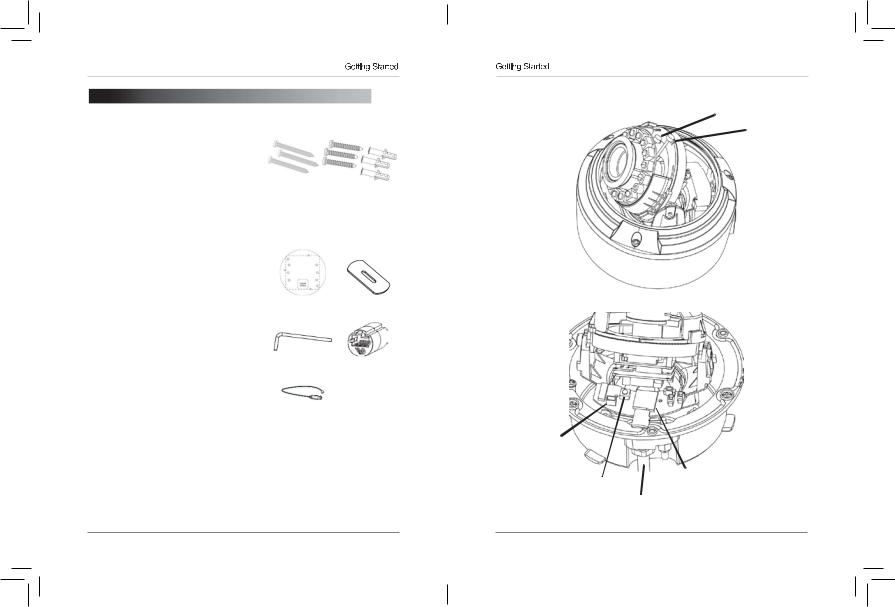
The system comes with the following components:
•1 x Camera
•6 x Camera locking screws (3x inside camera; 3x spare)
•1 x Surface mounting template
•1 x Junction box plate and screw kit
•1 x Mounting screw kit
•1 x Allen key
•1 x Conduit key
•1 x RJ45 coupler
•1 x BNC test cable
•1 x Instruction Manual
•1 x Quick Start Guide
•1 x Software/Documentation CD
Mounting Screw Kit:
•3 x 2.8in / 70mm screws
•3 x 1.2in / 30mm screws
•3 x 1.6in / 40mm anchors
Junction |
Conduit Key |
Box Plate |
|
1.1 Default Camera Username, Allen Key RJ45 Coupler Password, and Ports
Username: admin
Password: admin |
BNC Test Cable |
|
|
Ports: 80 (HTTP), 30001 (Control/Streaming), 8080 (RTMP), 554 (RTSP) |
|
IP Address: DHCP Enabled by Default (Router will automatically assign IP address)
NOTE: Once you have completed the basic setup of the camera, it is recommendedtoconfigure astatic IP address. This will prevent thecamera IP address changing in the event of a power failure. For details, see “8.7.1 Local Network” on page 30.
1.2 Camera Interior Overview
|
|
|
|
|
Front of Camera |
Zoom |
|
|
|
|
|
|
|
|
|
IR LED’s |
|
|
|
|
Focus |
||
|
|
|
|
||||
Camera Lens |
|
|
|
|
|
|
|
|
|
|
|
|
|
|
|
CdS Sensor |
|
|
|
|
|
|
|
|
|
|
|
|
|
||
Rear of Camera
BNCanalog
output
Reset button |
microSD card slot |
|
(max. 64GB supported; |
||
|
||
Termination cables SanDisk™/Kingston™ brand |
||
|
memory cards recommended) |
|
1 |
2 |
1.3 ONVIF Compatibility and Included Software Overview
This camera is ONVIF v2.1 compliant. It is designed for interoperability with popular VMS’s and NVR’s*, with backwards compatibility to ONVIF v.1.02. For more information on ONVIF, visit www.onvif.org
NOTE: Provided software is PC compatible only; Mac OS® access to the cameras is available via Safari® browser only.
1.3.1 Veilux VMS
•Veilux VMS is a client-only solution that supports up to 36 IP cameras. Veilux VMS is a free software provided on the CD.
•VeiluxVMS supports all the features of the camera. It can access microSD/ SD card recordings and camera setup over a local network.
•Veilux VMS manual is provided on the CD.
1.3.2 CD Tools
• CD contents Folders
IP Search |
|
; Search find IP Cameras and set IP address and gateway |
|
NTP Service Tool |
; Time Sync Application: IP devices match one PC system time. |
||
FTPUpdater |
|
; Firmware Update tool |
|
IP Support Help Files |
; Website support help documents for common problems. |
||
RTSP Tool |
|
; provides RTSP string command f. e.g VLC or Quick-time use |
|
SD Driver |
|
; Ext2 driver for Windows XP to read sd Memory card on PC |
|
Onvif_Help |
|
; documents on Onvif specifications |
|
Open the NTP service |
; Windows XP only enables NTP time to be enabled. |
||
Adobe Flash Player |
; Flash Video player for Windows IE plugin and Apple Mac OS |
||
Adobe AcrobatReader |
; Windows and Max OS Acrobat Reader v10 |
||
Files: |
|
|
|
IP_series_bitrate_calculator.htm |
; Simple storage calculator for IP devices |
||
Veilux VMS_Install.exe |
; NVR Software installation for PC |
||
Veilux |
VMS_Manual_1.7.pdf ; Guide to use the Veilux VMS Software |
||
SNMedia_Player.exe |
; File Player for recorded files / backup files from devices / |
||
Veilux VMS. |
|
|
|
Connection
2. CONNECTION
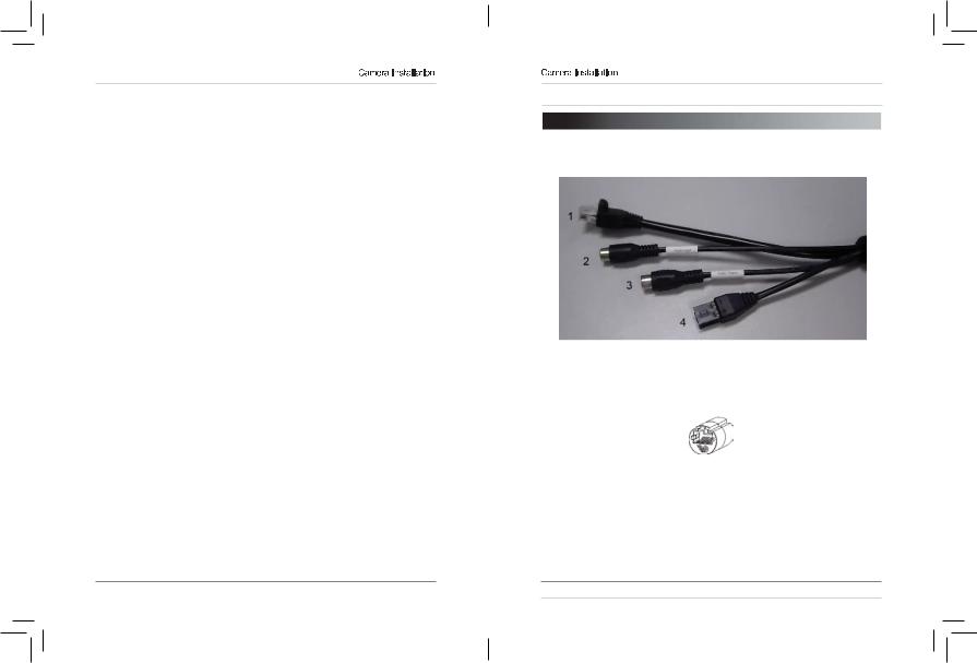
The camera has the following termination cables:
1.RJ45 Network Interface: Connect to a router or switch on your network using RJ45 Ethernet cable (Cat5e or better). 100Mhz connection. PoE supported (class 3 PoE switch required).
NOTE: Use the included RJ45 coupler to connect to male end of RJ45 Ethernet cable.
RJ45 Coupler
2.Audio Input (RCA): Connect to a self-powered microphone for listen-in audio.
3.Audio Output (RCA): Connect to an amplifier or self-powered speaker for intercom/2-way audio.
4.DC12V (1A): 12V DC power input terminal. Make sure to follow correct polarity (+/-) marked on the power connector when connecting to power.
•Minimum Power Requirement: 550mA / 6.6W.
3 |
4 |
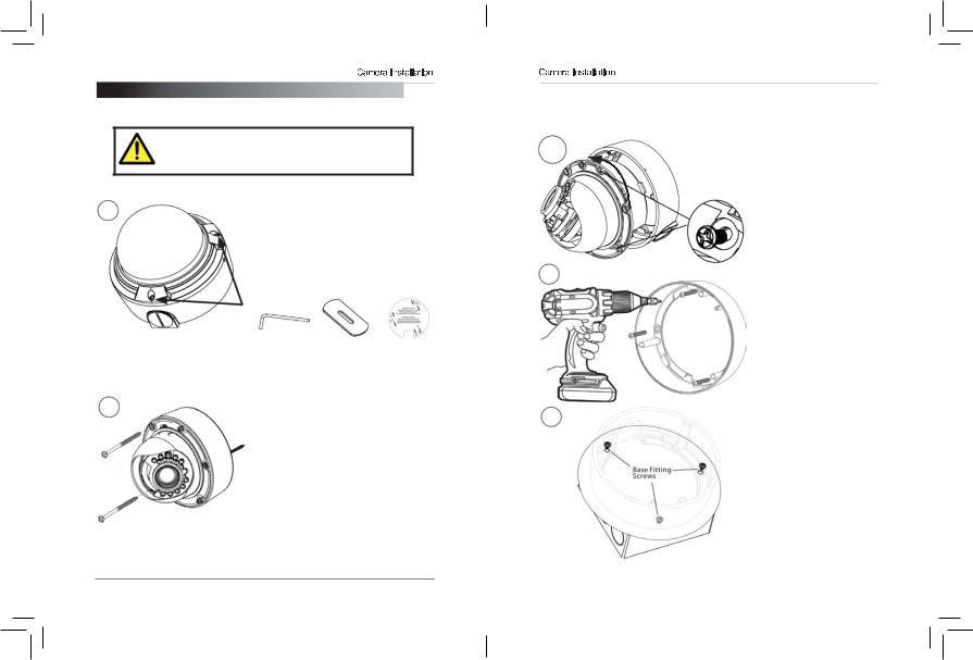
3. CAMERA INSTALLATION
Make sure to follow the correct polarity if connecting the camera to DC power. Polarity is marked on the power connector.
|
All Installation Methods |
|
1 |
1.Loosen the three tamper screws |
|
using the provided allen key. Lift the |
||
|
||
|
dome cover. |
|
|
NOTE: If you plan to use conduit fitting, |
|
|
remove conduit cap using the provided |
|
|
conduit key. |
Allen |
Conduit |
Mounting |
Key |
Key |
Template |
2a |
Method 1 - Direct Attach Install |
|
2a. Use the included mounting |
||
|
||
|
template (Installation Option 2) to mark |
|
|
and pre-drill the required holes. |
|
|
Remove 2 of the 3 base locking screws. |
|
|
Use 2pc of the 2.8” screws to mount the |
|
|
camera directly to the mounting |
|
|
surface. |
|
|
Remove the 3rd base locking screw and |
|
|
install the 3rd 2.8” screw. |
|
|
Go to step 4 to complete installation. |
5
Method 2 - Camera Base Install
2b. Use the included mounting template (Installation Option 1) to mark and pre-drill the required holes.
2c/2f |
2c. Remove the camera |
base by unscrewing the 3 |
|
|
base locking screws, and |
|
turn camera module |
|
approx. 5 degrees |
|
counterclockwise to detach |
|
camera base from the |
|
camera module. |
|
2d. Install the base to the |
|
correct holes as indicated |
2d |
on the mount template |
using the 1.2” screws. |
|
Go to step 3a to complete |
|
|
installation. |
|
|
Method 3 - Junction Box |
|
|
Install |
|
|
2e. Attach provided fitting |
|
|
plate to junction box (see “5. |
|
|
Junction Box Installation |
|
|
Types” on page 11). |
|
|
2f. Remove the camera |
|
2g |
base by unscrewing the 3 |
|
base locking screws, and |
||
|
||
|
turn the camera module |
|
|
approx. 5 degrees |
|
|
counterclockwise to detach |
|
|
camera base from camera |
|
|
module. |
|
|
2g. Install the base to the |
|
|
junction box plate using the |
|
|
base fitting screws. |
|
|
Go to step 3a to complete |
|
|
installation. |
|
|
|
|
|
6 |

3a
3b
4
Reattaching the Camera Module
3a. Reinsert camera module into camera base by aligning the arrow notches on the edge of the camera module and the camera base (label on edge of camera module indicates the location of the arrow notch), and turning camera module clockwise to lock into place.
3b. Use the 3 base locking screws to secure camera base to camera module.
Go to step 4 to complete installation.
4.Remove camera cover by squeezing the back and front of the cover (as indicated by the arrow indicators) at the same time and lifting it up and away from the lens.
5
Test cable |
terminals |
5.Insert a video test cable into the video test cable terminals and connect to a test monitor to set up camera.
Video Test Cable
6a
Thumb Screw
6b
6c
microSD card
6a. Adjust camera viewing angle and secure into place by tightening thumb screw using a flat head screwdriver.
Avoid pointing the camera lens in angles where the IR LEDs are blocked by the camera cover or dome cover. If IR LEDs are blocked, it may result in an unclear nighttime image.
6b. Adjust zoom and focus as required.
NOTE: Lens adjustment levers are by default in the locked position. Turn counterclockwise to unlock. Tighten levers to secure lens setting.
6c. (Optional) Insert a microSD card into the camera. To enable recording, you must format the microSD card and configure microSD recording (see “8.9.1 Record Directory” on page 43).
NOTE: The camera supports microSD cards up to a maximum size of 64GB. SanDisk™ or Kingston™ brand microSD cards are recommended.
6d. Re-attach the camera cover, using the thumb screw as a guide, until it snaps into place.
7 |
8 |
7 |
|
|
|
|
|
|
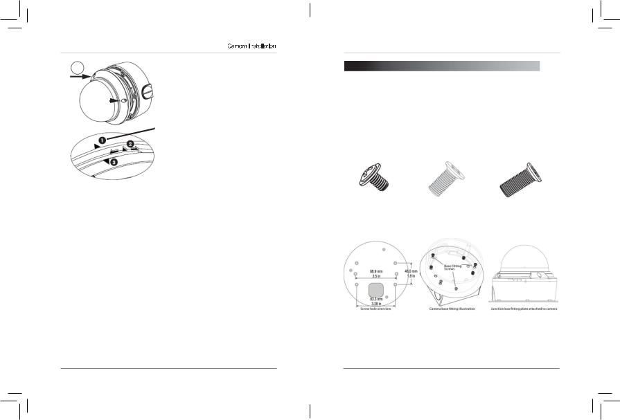
7.Re-attach the |
|
|
|
|
|
|
dome cover. |
|
|
|
|
|
|
|
|
|
|
|
|
|
|
|
|
Align the arrows |
|
|
|
|
|
|
|
as shown in the |
|
|
|
|
|
|
|
diagram to |
|
|
|
|
|
|
|
ensure a |
|
|
|
|
|
|
|
|
|
|
|
|
|
|
|
waterproof seal. |
|
|
|
|
|
|
|
Use the allen key |
|
|
|
|
|
|
Arrow on camera base |
to tighten the |
|
|
|
|
|
|
tamper screws. |
|
|
|
|
|
|
|
Arrow on camera |
|
|
|
|
|
|
|
|
|
|
|
|
|
|
|
module (inside camera) NOTE: Makesure |
|
|
|
|
|
|
|
|
dome cover cord |
|
|
|
|
|
|
Arrow on dome cover does not get |
|
|
|
|
|
|
|
||
caught in the rubber seal.
Correct Arrow Alignment
Junction 

4. JUNCTION BOX PLATE
Junction box plate is used to install camera into standard 4S and Octagon junction boxes. Junction box plate screw kit contains the following accessories:
•3 x Base fitting screws (PWM3 Type)
•4 x 2S / 4S plate screws (KM3.5 Type)
•2 x Octagon fitting screws (KM4 Type)
Base Fitting Screw |
Octagon Screw |
2S / 4S Screw |
4.1 Junction Box Plate Dimensions and Fitting
9 |
10 |
Junction Box Installation Types
5. JUNCTION BOX INSTALLATION TYPES
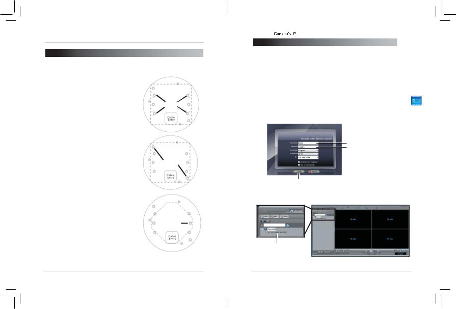
5.1 Two Gang Fitting (Recommended)
Two gang fitting requires 4x 2S/4S screws.
NOTE: Two gang fitting provides the most |
Screws |
robust installation. |
|
5.2 4S Fitting
4S fitting requires 2x 2S/4S screws.
|
|
Screws |
5.3 Octagon Fitting |
|
|
A 4" Octagon fitting requires 2x Octagon |
|
|
screws. |
|
|
NOTE: Screws used for the octagon fitting |
|
Screw |
are larger compared to those used for the |
|
|
|
||
2S/4S (M4 type). |
|
|
Finding the |
|
Address |
|
||
|
|
|
6. FINDING THE CAMERA’S IP ADDRESS
Use the steps below to find the camera’s IP address and connect to the camera over the local area network (LAN) using Veilux VMS, UPnP on Windows® 7, or Bonjour® in Mac OS®.
6.1 Finding the Camera’s IP Address Using Veilux VMS
1. Install Veilux VMS from the CD. Now Double-click the Veilux VMS icon ( |
) on the |
Desktop. The log in screen appears. |
|
2.Under User Name and Password, enter the default Veilux VMS user name (admin) and password (admin). Click Login.
Enter Admin
Enter Admin
Click Login
3.Veilux VMS opens and scans the local network for connected cameras. Detected camera IP addresses on the LAN appear in the Device List on the left side of the screen with a  icon.
icon.
Found camera
IP address
11 |
12 |
Finding the 

 Address
4.Click on a camera IP address in Device List to login.
5.Under User Name, enter the user name for the camera (default: admin). Under Password, enter the password for the camera (default: admin). Click Continue.
Enter Camera User Name (default: admin)
Enter Camera Password (default: admin)
Click Continue to login
6.The camera appears under the camera IP address. Click and drag the camera to the display grid to open it.
Click and drag the camera to the display grid to open it
NOTE: For detailed instructions on using Veilux VMS, see the Veilux VMS manual on the CD.
6.2 Finding the Camera’s IP Address using UPnP in Windows® 7
NOTE: To use this method, your router must support UPnP and the camera and computer must be on the same network. UPnP is enabled in the camera by default, and can be enabled/disabled using Veilux VMS (check the Veilux VMS manual for details).
Finding the 

 Address
1.Click Start>Computer>Network. The camera’s IP address appears under Network Infrastructure.
Double-click to open the camera
Network
2.Double-click the camera to open it in your default browser.
3.Under User Name and Password, enter the camera’s User Name (default: admin) and Password (default: admin) and click Login.
Enter Camera User Name (default: admin)
Enter Camera Password (default: admin)
Click Login
6.3 Finding the Camera’s IP Address using Bonjour® in
Mac OS®
NOTE: To use this method, the camera and computer must be on the same network. Bonjour® is enabled by default, and can be enabled/disabled using Veilux VMS (check the Veilux VMS manual for details).
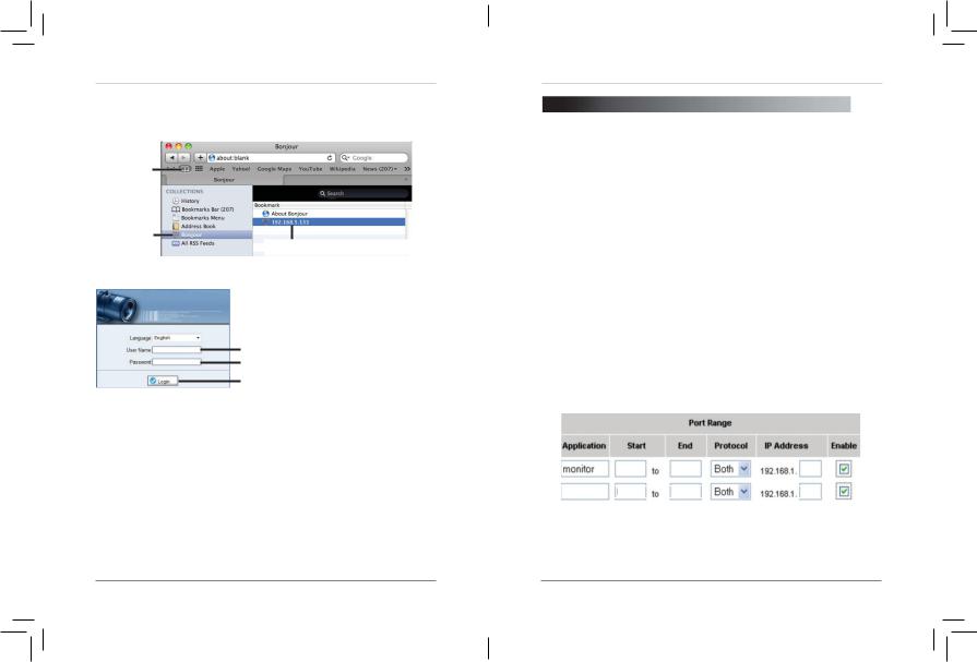
1. Open Safari® browser and click the Bookmarks button ( ).
).
13 |
14 |
Finding the 

 Address
2.Click Bonjour. The camera’s IP address appears in the Bonjour Devices list.
3.Double-click the camera to open it in Safari®.
Bookmarks button
Bonjour
Double-click the camera’s IP address
4.Under User Name and Password, enter the camera’s User Name (default: admin) and Password (default: admin) and click Login.
Enter Camera User Name (default: admin)
Enter Camera Password (default: admin)
Click Login
6.4 Finding the Camera IP using the BNC Test Cable
When the BNC test cable is connected to the camera, the IP address is shown on the test monitor. The camera must be connected to power to use the BNC test cable.
NOTE: The default IP address of 192.168.0.120 is shown if the camera cannot obtain an IP address from the router. Check the Ethernet/power connections and router configuration.
Configuring  Connection
7. CONFIGURING REMOTE CONNECTION
Follow the steps below to configure your camera for connections over the Internet using a web browser, Veilux VMS, or other VMS software.
Step 1 of 6: Locate the camera’s local IP address:
• See “4. Finding the Camera’s IP Address” on page 12.
Step 2 of 6: Port Forward your router:
You need to enable port forwarding for the following ports on your router to the camera’s local IP address:
•HTTP Port (default: 80)
•Control Port (default: 30001)
NOTE: If you are configuring multiple IP cameras for individual remote access, you must change the ports for each camera. Two cameras cannot use the same port number.
NOTE: Port forwarding the RTSP and RTMP ports is not necessary unless your installation has special requirements.
There are two methods for port forwarding:
•Youcanmanually port forward yourrouter. See your router’s user manual for details. An example of a port forwarding screen is shown below.
|
|
80 |
80 |
100 |
HTTP |
||||
Control |
30001 |
30001 |
100 |
|
15 |
16 |
 Loading...