


SVR-824DVD

1

2
FCC Compliance Statement
Possible injury or product damage.
Risk of minor injury or product damage.
Cautions for the usage of the product.
Information for the usage of the product.
This device complies with Part 15 of the FCC Rules. Operation is Subject to the following two conductions: (1)
this device may not cause harmful interference, and (2) this device must accept any interference received,
including interference that may cause undesired operations.
WARNING
Unauthorized reproduction of all or part of this manual is strictly prohibited.
The figures in this manual are for illustration purposes only (may differ from the actual product).
The specifications and design of the product are subject to change without prior notice for purposes of quality
improvement.
CAUTIONS
To get the best use out of the product, be sure to read the cautions before using the product. For safety, please
take note of the following.
Instructions before using the product
1 To prevent electric shock when installing, moving, or opening the DVR and peripheral devices, connect
and disconnect the cables as instructed. All cables must be connected to grounded power outlets.
2 If the product is installed near a power outlet, make sure it can be unplugged easily.
3 Do not use the DVR in water or in wet places.
4 Keep the plastic packing materials used for the DVR or other peripheral devices out of reach of children
(may cause suffocation).
Installation Environment of the DVR
1 Maintain the following conditions: operating temperature of 5˚C ~ 40˚C; operating humidity of 10% ~
80%.
2 Install the DVR in a safe place that is free from external vibration.
3 Install the DVR in a well-ventilated place.
4 To protect the hard disk from data loss and breakdown, install the DVR away from magnetic materials.
5 When using a rack other than the standard one, use a separate table with sufficient spacing, i.e., 60cm
from the floor, 50cm from the ceiling, and 20cm from the side and back walls and other objects.
Safety Notes on the DVR
1 When installing additional boards and HDD, separate the power cable and turn OFF power supplied to
the DVR completely..
2 Keep the product away from heat-generating devices such as heaters.
3 Do not use a damaged power cord.
4 To prevent problems due to magnetic interference and electric surge, use only grounded cables and
power outlets.
5 If the power cord is connected, do not touch the power unit. If the power cord is connected, electric
current is still flowing internally even after the switch is turned OFF.
6 Do not place a heavy object on top of the product.
7 Do not drop a conductive object in the ventilation holes.
8 Allot sufficient space for system cabling.
9 Use only the parts indicated in the manual. Do not disassemble, repair, or modify the product without
permission.
10 Incorrect system setup may cause malfunction.
11 Shut down the system normally as instructed in the manual.
Safety Notes on the Lithium Battery
1 Replace lithium batteries as instructed to avoid danger.
2 Dispose used lithium batteries properly.
【Warning and Caution are indicated as follows.】
3
Chapter 1. SVR-SVR***D1 ..................................................................................................... 7
1-1 Introduction of the SVR-***D1 .................................................................................. 7
1-2 Installation and Connection .................................................................................... 10
1-3 Operations & Setup Tools ...................................................................................... 14
1-4 DVR Operation Setup ............................................................................................ 17
Chapter 2. VRDH-*-4SDI / VRHD-*-4SDI-DVD ................................................................... 19
2-1 Introduction of the VRDH-*-4SDI / VRDH-*-4SDI-DVD…………..……………….….19
2-2 Installation and Connection…………………………………………………………..….25
2-3 Operation & Setup Tools ........................................................................................ 28
2-4 DVR Operations Setup ........................................................................................... 31
Chapter 3. SVR-***DVD & VR-***E ........................................................................................ 33
3-1Introduction of the SVR-***DVD & VR***E ............................................................... 33
3-2Installation and Connection ...................................................................................... 36
3-3Operation & Setup Tools .......................................................................................... 41
3-4DVR Operation Setup .............................................................................................. 45
Chapter 4. System Hard Drive Setup ................................................................................ 47
4-1 Power ON. ................................................................................................................ 47
4-2 HD frequency setting ................................................................................................ 47
4-3 Storage Setup ........................................................................................................... 48
4-4 Recording Setup ....................................................................................................... 48
4-5 Date/Time Setup ....................................................................................................... 48
4-6 Definition ................................................................................................................... 48
4-7 Screen View and Other Setup .................................................................................. 48
4-8 External Device Setup .............................................................................................. 48
4-9 Recording View ......................................................................................................... 48
4-10 Backup .................................................................................................................... 48
4-11 DVR Information View ............................................................................................ 48
Chapter 5. System Operation ............................................................................................ 49
5-1 Real Time Monitoring Mode and Icon .................................................................... 49
5-2 System Login .......................................................................................................... 50
5-2-1 User Account and Authorization ................................................................................. 50
5-2-2 Login........................................................................................................................... 50
5-2-3 Logout ........................................................................................................................ 51
5-3 Monitoring ............................................................................................................... 51
5-3-1 Screen Division and Auto Sequence .......................................................................... 51
5-3-2 Channel Grouping ...................................................................................................... 52
5-3-3 Spot ............................................................................................................................ 52
5-3-4 Menu in Monitoring Mode ........................................................................................... 53
5-3-5 Zoom .......................................................................................................................... 53
5-3-6 Screen Control by using PTZ ..................................................................................... 54
5-4 System Information and Screen Setup Change ..................................................... 55
5-4-1 System Information .................................................................................................... 55
5-4-2 Screen Brightness/Contrast/Color/Saturation/Sharpen/Camera Adjustment .............. 56
5-4-3 Display Setting ........................................................................................................... 56
5-5 Control .................................................................................................................... 57
5-6 Search .................................................................................................................... 57
5-6-1 Search Mode .............................................................................................................. 57
5-6-2 Playback Menu ........................................................................................................... 57
5-7 Calendar Search .................................................................................................... 58
5-7-1 Search Mode .............................................................................................................. 58
5-7-2 Year/Month/Day Selection .......................................................................................... 58
5-7-3 Time Index .................................................................................................................. 58
5-7-4 Event .......................................................................................................................... 58

4
5-7-5 Multi-Channel Search ................................................................................................. 58
5-7-6 Multi-Time Search ...................................................................................................... 59
5-7-7 Multi-Day Search ........................................................................................................ 59
5-8 Playback ................................................................................................................. 59
5-8-1 Playback and Playback Speed Control....................................................................... 60
5-8-2 Smart Search ............................................................................................................. 61
5-8-3 PCD Search ............................................................................................................... 61
5-8-4 Calendar Search ........................................................................................................ 62
5-8-5 MULTI TIME ............................................................................................................... 62
5-8-6 MULTI DAY ................................................................................................................ 62
5-8-7 MULTI CHANNEL ...................................................................................................... 62
5-8-8 Panorama Play ........................................................................................................... 62
5-8-9 Event .......................................................................................................................... 62
5-8-10 Audio ....................................................................................................................... 62
5-8-11 Backup .................................................................................................................... 62
5-8-12 Screen Mode .......................................................................................................... 62
5-9 Log Viewer ............................................................................................................. 63
5-9-1 Log Type .................................................................................................................... 63
5-9-2 System Log Viewer .................................................................................................... 63
5-10 Recording ........................................................................................................... 64
5-10-1 Recording Types ..................................................................................................... 64
5-10-2 Recording Setup ..................................................................................................... 64
5-10-3 Recording Status View............................................................................................ 64
5-11 Backup ................................................................................................................ 65
5-11-1 Backup in The Real-Time Monitoring Mode ............................................................ 65
5-11-2 Backup in Search Mode .......................................................................................... 65
5-11-3 Backup in Log Mode ............................................................................................... 65
5-11-4 Backup in Playback Mode ....................................................................................... 66
5-11-5 Common Backup Procedure ................................ ................................ ................... 66
5-12 Setup Backup ..................................................................................................... 66
5-13 Log Backup ......................................................................................................... 67
5-14 Print .................................................................................................................... 68
5-15 NAS Backup ....................................................................................................... 68
5-16 Snapshot ............................................................................................................. 68
Chapter 6. Setup ................................................................................................................. 69
6-1 Time ....................................................................................................................... 69
6-1-1 Time Sever ................................................................................................................. 69
6-1-2 Date and Time ............................................................................................................ 69
6-1-3 Standard Time Zone ................................................................................................... 70
6-2 Definition ................................................................................................................ 70
6-2-1 Camera ....................................................................................................................... 71
6-2-2 POS ............................................................................................................................ 71
6-2-3 Event Source ................................................................................................ .............. 75
6-2-4 Relay .......................................................................................................................... 75
6-3 Action ..................................................................................................................... 76
6-3-1 Schedule Selection (Schedule1 ~ Schedule4)............................................................ 76
6-3-2 Event .......................................................................................................................... 76
6-3-3 Recording ................................................................................................................... 76
6-3-4 Alarm .......................................................................................................................... 77
6-3-5 Duration ...................................................................................................................... 77
6-3-6 Log ............................................................................................................................. 77
6-3-7 Advanced ................................................................................................................... 77
6-4 Schedule ................................................................................................................ 78
6-4-1 Schedule Setup .......................................................................................................... 78
6-5 Storage ................................................................................................................... 79
6-5-1 Private Recording ....................................................................................................... 79
6-5-2 HDD Overwrite ........................................................................................................... 79
6-5-3 Local Storage Management ....................................................................................... 79
6-6 Network .................................................................................................................. 82

5
6-6-1 Ethernet ...................................................................................................................... 82
6-6-2 ADLS .......................................................................................................................... 82
6-6-3 DDNS ......................................................................................................................... 82
6-6-4 Port ............................................................................................................................. 83
6-6-5 E-mail ......................................................................................................................... 83
6-6-6 Bandwidth ................................................................................................................... 83
6-6-7 Call Back .................................................................................................................... 83
6-7 System ................................................................................................................... 85
6-7-1 DVR Name ................................................................................................................. 85
6-7-2 ID for Remote Controller............................................................................................. 85
6-7-3 ID For Keyboard Controller ......................................................................................... 86
6-7-4 User Registration ........................................................................................................ 86
6-7-5 Admin. Password ....................................................................................................... 86
6-7-6 Upgrade ...................................................................................................................... 86
6-7-7 Factory Default ........................................................................................................... 87
6-7-8 Sensor POS/Port ........................................................................................................ 87
6-7-9 Error Alarm Action ...................................................................................................... 87
6-7-10 Error Alarm Duration ............................................................................................... 88
6-7-11 Menu Time Out ....................................................................................................... 88
6-7-12 Language ................................................................................................................ 88
APPENDIX .............................................................................................................................. 89
(1) Recommended PTZ Camera Protocol ........................................................................ 89
(2) Recommended USB2.0 Device .................................................................................. 89
6
QUALITY GUARANTEE
For any camera produced by Veilux, we promise 2 year to repair warranty
. During Guarantee period, we supply free service except following situations:
User does not operate as manual book requires
User un-install the whole product by themselves
If there are additional agreements between Veilux and buyer, then agreements shall be strictly
done.
COMPANY COMITTMENT
Lightening or Act of God
Veilux owns the final design changing and final specification rights and no
responsibility to inform user.
permits or any book inform, any company or private copy of whole or part of the
book shall be prohibited.
802
GREENVIEW
GRAND PRAIRIE,
Website:
E-mail:
Phone
www.veilux.net
Sales@veilux.net
# 1-800-510-6528
DR
STE
200
TX. 75050
This manual book belongs to Veilux rights, without
7
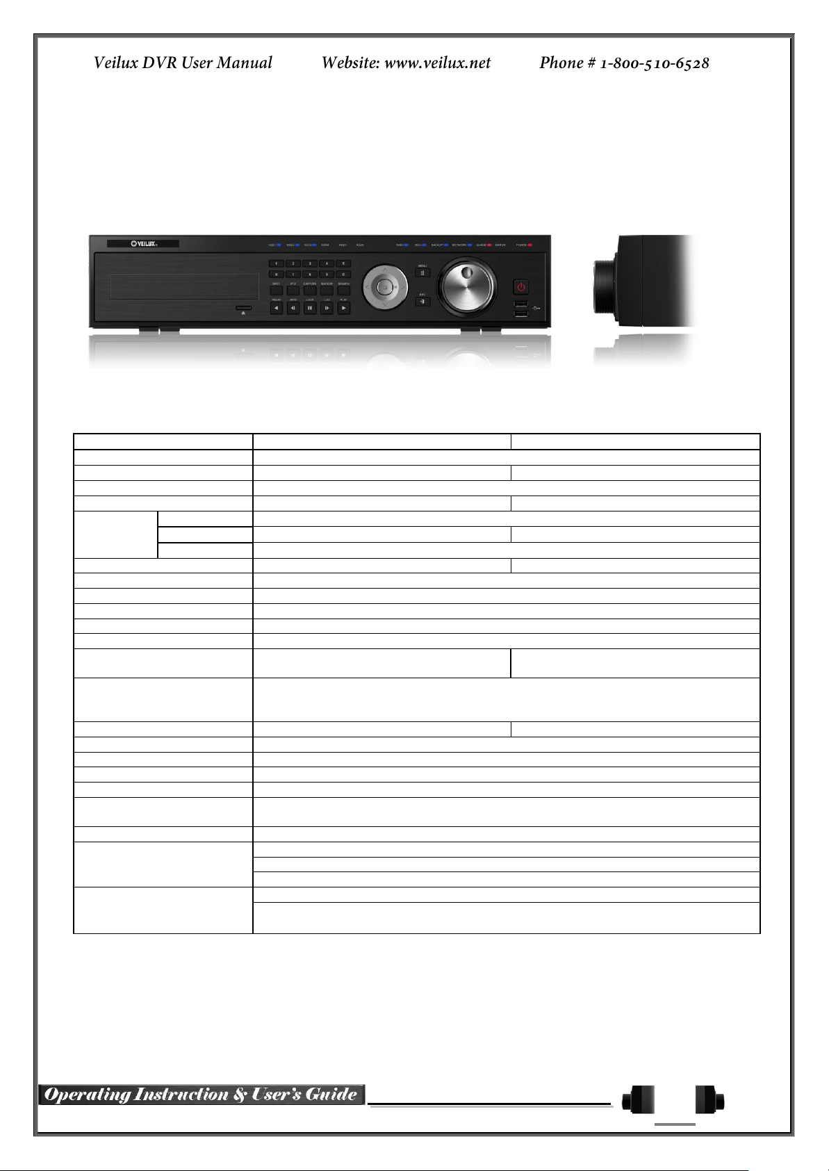
Chapter 1. SVR-SVR***D1
VR-1648D1E
VR-824D1E
System
Reliable Standalone DVR
Format
16Ch – D1 480/400
8ch – D1 240/200
OS
Embedded Linux - Built in Flash Memory
Video Input
16 BNC
8 BNC
Video
Output
Monitor
1 BNC, 1 VGA, 1 HDMI
Loop
16 BNC
8 BNC
Spot
1 BNC - Single or Quad
Audio Input
Line Input : 16 RCA
Line Input : 8 RCA
Audio Output
Line Output : 1 RCA
Compression Format
Video : Standard H.264 / Audio : G.723
Recording Speed
1/8, 1/4, 1 ~ 30(25)fps, Total max. D1 480/240(400/200)fps
Recording Resolution
CIF, 2CIF, 4CIF
Recording mode
Continuous, Event (Sensor, Motion, Audio, Pattern, Text), Schedule
Alarm Interface
16 Sensor Input, NC/NO - Terminal Block
4 Relay Output, NC/NO - Terminal Block
8 Sensor Input, NC/NO - Terminal Block
2 Relay Output, NC/NO - Terminal Block
Video Output Resolution
HDMI : Full HD(1920x1080), WSXGA+(1680x1050), SXGA(1280x1024)
VGA : WSXGA+(1680x1050), SXGA(1280x1024)
BNC : SDTV(720x480(576))
POS / ATM Interface
8 RS232C Simplex - Terminal Block
4 RS232C Simplex - Terminal Block
Backup & Copy Access
DVD-RW, USB2.0, Network
Network Access
Ethernet 10/100 - RJ45
PTZ / Controller Access
RS485 Half Duplex - Terminal Block
Internal HDD / Internal ODD
SATA HDD Max. 3ea / SATA Type DVD 1ea
System Operation &
Adjustment
Front Panel Button, Jog/Shuttle, Mouse, IR Remote Control, Keyboard Controller,
Network
System Upgrade
USB2.0 Memory Stick, Network
Network
System Automation (Controlled by CMS)
NTP Supported
CMS / Monitoring by Web Browser / PDA
Others
17 Languages Supported, Automatic E-mail
Power [12V/5A] / Max. Power Consumption[60W] / Operating Temperature[5-40℃]
Weight without HDD[8kg] / Dimension[440*88*430mm]
1-1 Introduction of the SVR***D1
SVR-***D1 series Major Features
8
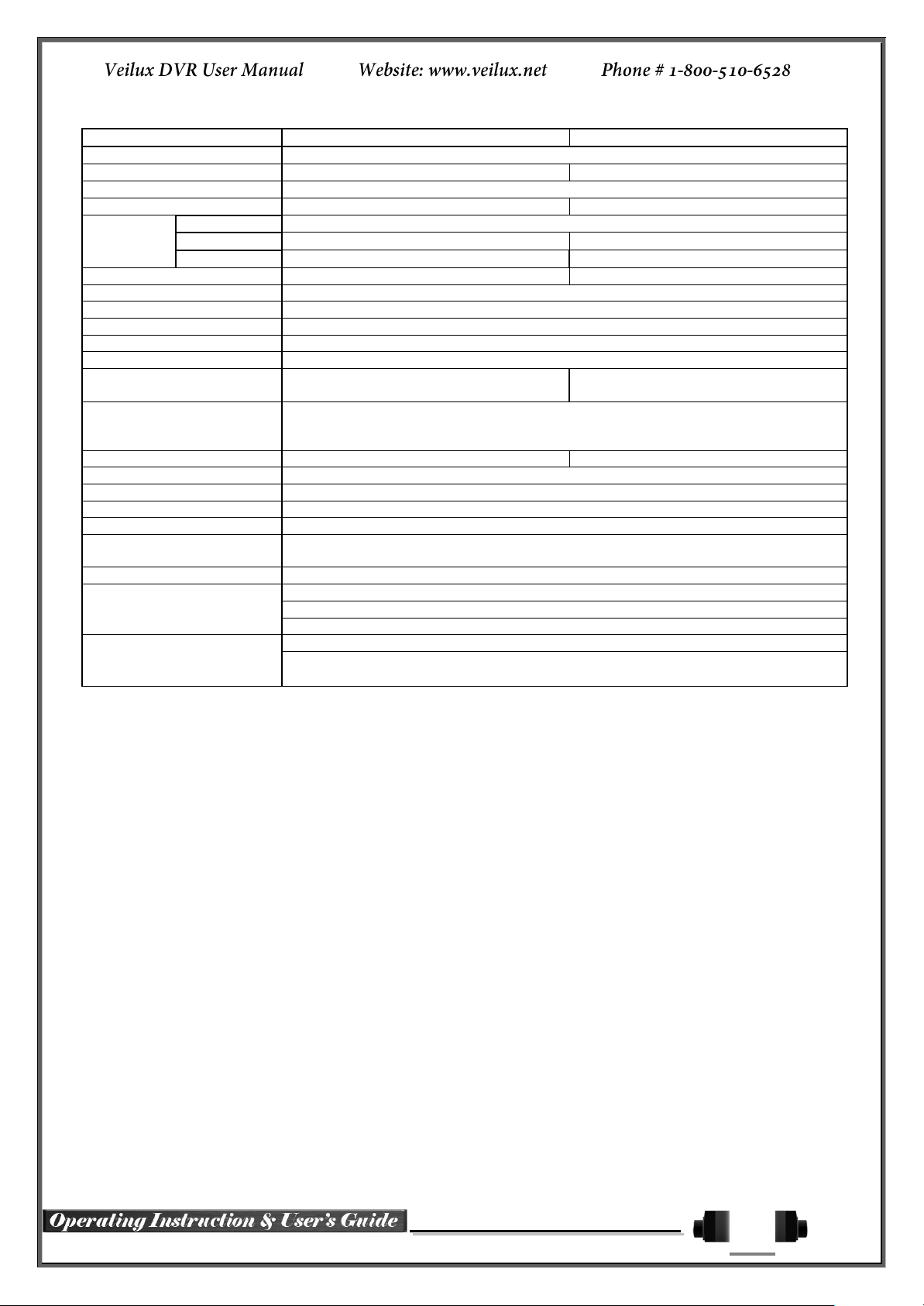
SVR-1648D1
SVR-1648D1
System
Reliable Standalone DVR
Format
16Ch – D1 480/400
8ch – D1 240/200
OS
Embedded Linux - Built in Flash Memory
Video Input
16 BNC
8 BNC
Video
Output
Monitor
1 BNC, 1 VGA, 1 HDMI
Loop
16 BNC
8 BNC
Spot
4 BNC - Single or Quad
1 BNC - Single or Quad
Audio Input
Line Input : 16 RCA
Line Input : 8 RCA
Audio Output
Line Output : 1 RCA
Compression Format
[Video : Standard H.264)] / [Audio : G.723]
Recording Speed
1/8, 1/4, 1 ~ 30(25)fps, Total max. D1 480/240(400/200)fps
Recording Resolution
CIF, 2CIF, 4CIF
Recording mode
Continuous, Event (Sensor, Motion, Audio, Pattern, Text), Schedule
Alarm Interface
16 Sensor Input, NC/NO - Terminal Block
4 Relay Output, NC/NO - Terminal Block
8 Sensor Input, NC/NO - Terminal Block
2 Relay Output, NC/NO - Terminal Block
Video Output Resolution
HDMI : Full HD(1920x1080), WSXGA+(1680x1050), SXGA(1280x1024)
VGA : WSXGA+(1680x1050), SXGA(1280x1024)
BNC : SDTV(720x480(576))
POS / ATM Interface
8 RS232C Simplex - Terminal Block
4 RS232C Simplex - Terminal Block
Backup & Copy Access
eSATA, DVD-RW, USB2.0, Network
Network Access
Ethernet 10/100/1000 - RJ45
PTZ / Controller Access
RS485 Half Duplex - Terminal Block
Internal HDD / Internal ODD
SATA HDD Max. 6ea / SATA Type DVD 1ea
System Operation &
Adjustment
Front Panel Button, Jog/Shuttle, Mouse, IR Remote Control, Keyboard Controller,
Network
System Upgrade
USB2.0 Memory Stick, Network
Network
System Automation (Controlled by CMS)
NTP Supported
CMS / Monitoring by Web Browser / PDA
Others
17 Languages Supported, Automatic E-mail
90 ~ 250V, 50/60Hz , 80 Watts / Operating Temperature [5 ~ 40℃]
Weight without HDD [8kg] / Dimension [440 x 88 x 430 mm]
Components
After unpacking the product, check whether following accessories are included.
- Remote Controller
- DVD (VMS Software, VMS Manual, DVR User Manual, How to Videos, & Our Products)
- AAA 1.5V Batteries 2ea
- Adapter (12VDC/5A)
- Handle

9
HD1 Product Introduction
D1(4CIF) real-time recording
16Ch audio recording
4Ch spot output (SVR-1648D1) / 2Ch spot output (SVR-1648D1E)
Various video output port (HDMI, VGA, BNC)
Various video output mode (Full HD, WSXGA+, SXGA, SDTV)
6 HDD bay
Jog-shuttle
8Ch POS/ATM interface
Pre-alarm recording
Watermarking & watermarking detection
Auto e-mailing notification max. of 5 users
Privacy zone mask
Covert channel
Digital single/multi-zoom
Smart search
Pattern change / Text detection/search
Multi-time/day, Index (event) search/playback
Panorama playback
Data backup to NAS over Ethernet
Still image capture Full HD resolution
Direct printer connection through USB2.0
Firmware upgrade at a remote PC site
Remote setup, backup, relay control
USB/DVD backup with self-executable player (quick viewer)
Web monitoring in PC (Built in web server)
PDA viewer (Windows mobile)
Mobile web viewer (3G viewer)
NTP, DST, DDNS, DHCP

10
1-2 Installation and connection
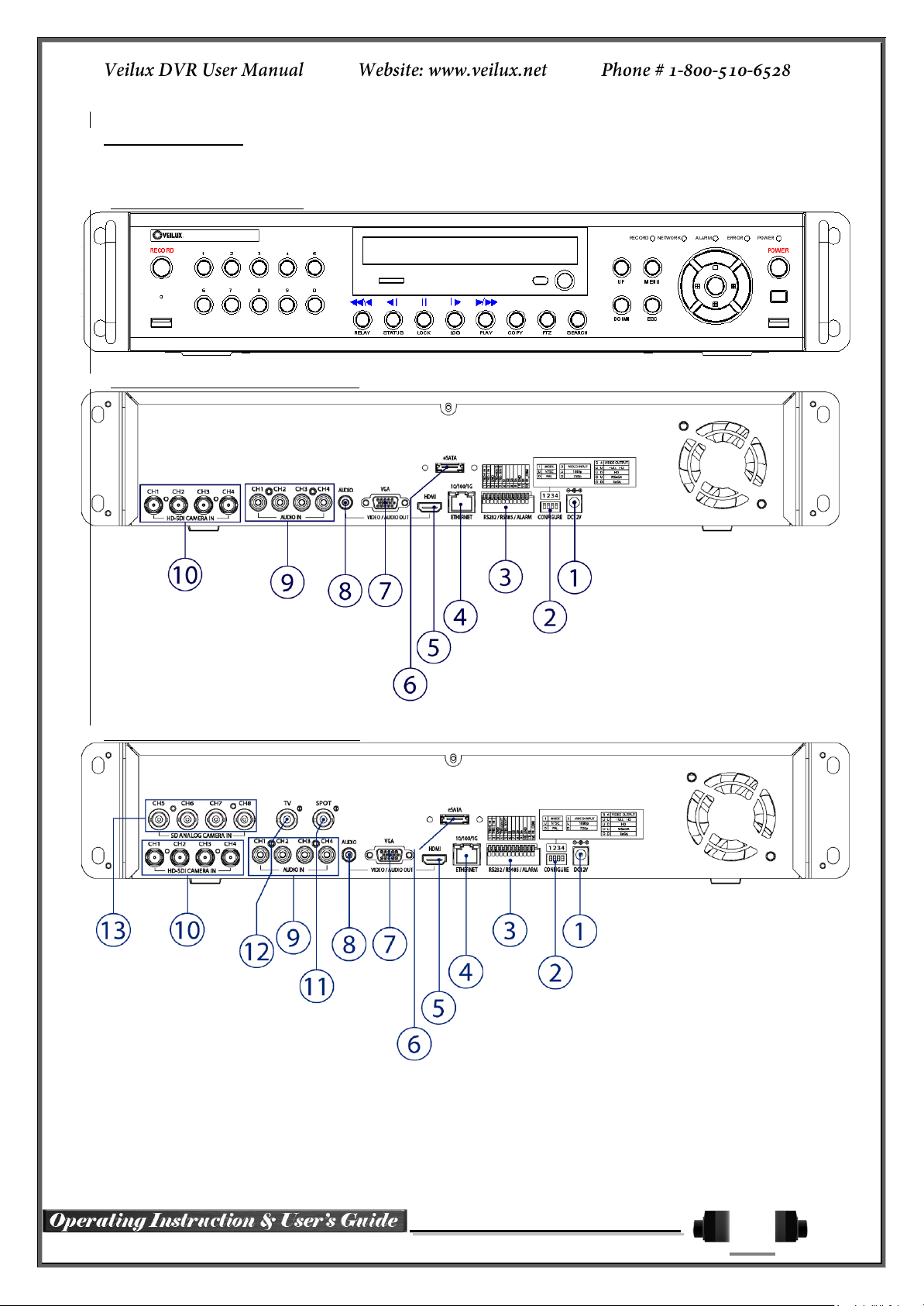
SVR-***D1 series Names and Features of Each Part
VR-1648D1E Rear Panel
VR-824D1E Rear Panel
SVR-1648D1 Rear Panel
SVR-824D1 Rear

11
No.
Name
Feature
Type
1
DC 12V IN
Power cable connection to the body (VR-***D1E series)
DC-power jack
2
Terminal Block
RS-485 / SENSOR IN / RELAY OUT / RS-232C
Terminal Block
3
SPOT
CCTV monitor connection to output images of the channel
generating an event signal
BNC
4
TV OUT
CCTV monitor connection
BNC
5
AUDIO OUT
Audio Output Connection(Line Only Output)
RCA
6
HDMI
HDMI Output
HDMI type-C
7
VGA-OUT
VGA Monitor or LCD Monitor Connection
D-SUB 15P
8
Ethernet
ADSL, Cable Modem, Ethernet 10/100 Base-T, Network Connection
RJ-45
9
RS-232C
Console Output
D-SUB 9P
10
CONFIG
NTSC/PAL
VGA/TV
Full HD(1920x1080), HD(1920x1080)
WSXGA+(1680x1050), SXGA(1280x1024)
DIP S/W, 4-pin
11
USB2.0
USB2.0 / e-SATA
(VR-***D1E series)
(SVR-***D1 series)
USB Type A,
e-SATA
12
CAMERA IN
Video Camera Connection
BNC
13
LOOP OUT
Video Signal loop-back Output Connection
BNC
14
AUDIO IN
Audio Input Connection
RCA
15
Ventilating
Opening
(SVR-***D1 series)
Power supply Fan
16
Power
90 ~ 250V, 50/60Hz, 80 Watts (SVR-***D1 series)
AC Inlet
(3p, female)
Installation and Connection
[Figure 2-1. VR-1648D1E Basic Connection and Device Connection]

12
Connection
Order
Connection Device
DVR Terminal
1
CCTV Camera
Rear Panel Video IN
2
CONFIG SWITCH Setup
Rear Panel Left 4ea Switch
(Refer to below; CONFIG SWITCH Setup)
3
CCTV Monitor
Rear Panel TV
4
VGA Monitor / LCD Monitor
Rear Panel VGA-OUT
5
HDMI Monitor
Rear Panel HDMI
6
Mouse
Rear Panel USB
Switch 1
Switch 2
Switch 3
Switch 4
Switch 3 / 4 Resolution
FULL HD ( 1920 * 1080 )
HD ( 1920 * 1080 )
WSXGA+ ( 1680 * 1050 )
SXGA ( 1280 * 1024 )
※ In the TV mode, GUI is not displayed through VGA/HDMI output but only a channel
title is shown.
※ Only VGA is available in higher than the HD mode.
SVR***D1 series has differences in feature as described below. Be
cautious.
Item
VR-***D1E series (1648/824)
VR-***D1 series (1648/824)
Internal HDD
Bay
3 SATA
6 SATA
Spot
1 BNC - Single or Quad
4/1 BNC - Single or Quad
[Figure 2-2. SVR-1648D1 Basic Connection and Device Connection]
Basic Connection
By referring to above [Figure 2-1] ~ [Figure 2-2], make a connection accordingly.
CONFIG SWITCH Setup
Connection of Other Devices

13
Item
1648 series
824 series
Audio
16
8
Sensor
16
8
Relay
4
2
POS
8
4
Connecting Device
DVR Terminal
1
SPOT Monitor(CCTV Monitor)
Rear Panel SPOT
2
Mike / Speaker
Rear Panel Audio Input / Audio Output
3
LAN Cable
Rear Panel Ethernet
4
PTZ Camera
Rear Panel Terminal Block
5
Sensor / Relay / POS
Rear Panel Terminal Block
6
Keyboard controller
Rear Panel Terminal Block
PTZ Camera may not be working properly if GND is not connected.
Connect the PTZ controller cable, audio input/output, network, and sensors as shown below.
1) SPOT Monitor
Connect Spot Monitor to the rear SPOT terminal.
SVR-1648D1 supports 4ea SPOT terminals and VR-1648D1E / VR-824D1E / SVR-824D1 support 1ea SPOT
terminal.
2) Audio Input / Output
VR-1648D1E / SVR-1648D1 support 16ea audio inputs and VR-824D1E / SVR-824D1 support 8ea audio inputs.
The SVR-1648D1, VR-1648D1E, SVR-824D1, VR-824D1E all support 1ea output.
3) Terminal Block
[Figure 2-3 . HD1-1648 series Terminal Block and Description]
[Figure 2-4. VR-824D1E & SVR-824D1 series Terminal Block and Description]
The terminal blocks in the rear of the product are for the connection of PTZ / Sensor / Relay / POS Connection.
The number of the terminal block may be different depending on the model.
PTZ Camera/Keyboard Controller
Connect PTZ control cable; TRX+, TRX- and GND to Terminal Block(TB1);No.4 TRXD+, No.5 TRXD- and
No.10 GND in the rear of DVR. You may refer to APPENDIX for supported PTZ cameras in this manual.
Keyboard controller has the same connection as PTZ camera.

14
Sensor/Relay /POS
Sensor and Relay Type
NC(Normal Close) : Normally closed; opens when a signal is received
NO(Normal Open) : Normally open; closes when a signal is received
The external alarm device may require the power supply depending on its type.
Be cautious.
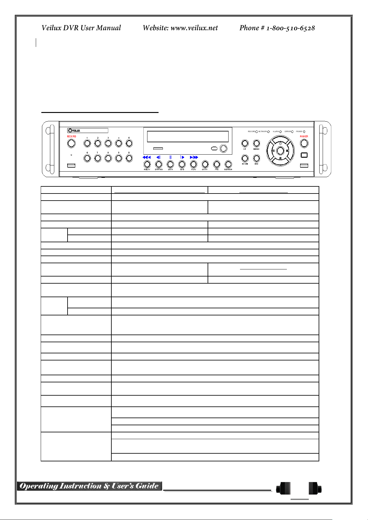
No.
Name
Function
1
Veilux logo
Veilux Logo
2
LED DISPLAY
HDD and System Power and Status Indication LED
3
Number Button
Channel Selection or Number Input
4
MOVE & DISPLAY & Select
Move from one category to another or change to the
display mode or select
5
MENU
Various Modes
6
JOG & SHUTTLE
Speed in Playback Mode / Play Direction / Frame Play
7
POWER
Turn the system power ON or OFF
8
USB Port
Connection port to the USB mouse and USB memory
stick
9
ESC
Exit the current menu or move to the upper menu
10
SPOT
Spot Control
PTZ
PTZ Pan/Tilt/Zoom Control
CAPTURE
Capture the displaying image into USB
BACKUP
Save the recorded image at other media.
SEARCH
Search the recorded Image.
11
Reverse Play / Fast Reverse
RELAY
Backward Playback/Rewind (in the Playback Mode)
Relay Control (in the Monitoring Mode)
Reverse Frame by Frame
STATUS
Backward Playback Frame by Frame (in the Playback
Mode)
View System Configuration (in the Monitoring Mode).
Connect Sensor/Relay/POS to the terminal block directly depending on the model.
(1) Sensor Connection
① Connect the sensor to the terminal block S1 ~ S16 depending on the model.
Each input terminal is connected relatively with the channel number.
(2) Relay Connection
① Relay the output signal to external devices such as Alarm and Siren.
② Connect the relay to R1/R2/R3/R4 terminal block depending on the model
(3) POS Connection
① Connect the POS device.
Connect the POS to Terminal Block RXD1 ~ RXD8 depending on the model.
1-3 Operation and Setup Tools
SVR-***D1 series can be controlled easily by using the front panel buttons, front panel, jog/shuttle, remote
controller and mouse.
SVR-***D1 series Front Panel Button

15
Pause
LOCK
Pause (in the Playback Mode)
Lock (in the Monitoring Mode)
Forward Frame by Frame
LOG
Playback Frame by Frame (in the Playback Mode)
System Log View(in the Monitoring Mode)
Forward Play / Fast Forward
PLAY
Playback/Fast Forward (in the Playback Mode)
Play back (in the Monitoring Mode)
12
Eject
CD, DVD Eject Button
13
ODD
CD-RW, DVD-RW
1
2 3
4
5 6
7
8 9
0
UP
DOWN
ESCMENU
POWER
SEARCH
RECORD
PTZ
RELAY
STATUS LOCK LOG
PLAY
ID
COPY
A) Basic Control Button
POWER
Turn the system power
ON or OFF.
RECORD
Record all channels or stops recording
all channels.
1
~0
NUMBER
Input of numeric data.
ID
ID
Set up the remote controller ID.
B) System Operation and Setup Button
MENU
Data, Schedule, System Set up
ESC
Exit the current menu
or Move to the upper menu.
SEARCH
Search recorded images.
SELECT
Select the category or execute
automatic screen conversion.
COPY
Copy recorded videos.
PTZ
Shift to the PTZ camera control mode.
MOVE
Move from one category to another or
change to the display mode.
UP/
DOWN
Log Page Up/Down
PLAY
Play /
Fast Forward
Play/Fast-forward
LOG
Frame by Frame
Play forward frame by frame
LOCK
Pause
Pause
STATUS
Reverse Frame by Frame
Reverse play frame by frame
RELAY
Reverse Play /
Fast Reverse
Reverse play/ Rewind
PLAY
PLAY
Play the recorded images.
LOG
LOG
View the system
log list.
LOCK
LOCK
Lock the system
STATUS
STATUS
View system information and changes the
display setup.
SVR-***D1 series Remote Controller
C) Search Button (Playback Mode)
D) Buttons for Other Features (Monitoring Mode)

16
RELAY
RELAY
View the relay status and manual operation.
※ Setting up the remote controller ID
Example) When the remote controller ID is set to 1
Press the {ID} button, enter {0} and {1}, and press the {ID} button again.
To control all DVRs with the different ID, set the remote controller ID to 999.
Mouse Control functions are shown below.
Click on the right
button
Monitoring Mode / Move from Play Mode to Monitoring
Menu / Pop up or remove Play Menu.
Show sub-folder of the certain Menu window.
Click on the left
button
Select Menu.
Double click on the
left button
Select Menu.
Click the left button
and drag
Move a certain window.
Front
Side
Speed and Direction Control
Frame Control
※ Play Direction Control
This is available in the playback mode. Turning the jog right/left plays
forward/reverse frame by frame.
※ Speed and Direction Control
This is available in the playback mode. Turning the jog right/left plays
forward/reverse x1/x2/x4x30.
Mouse
The mouse pointer as shown below appears if a mouse is connected to the USB terminal at the front panel.
Jog/Shuttle
In the playback mode, control the play direction, speed and frame.

17
Type
Size
Capacity
Buffer
RPM
SATA I, II
3.5“ 1, 2 Flat
Up to 2TB
16MB or
More
7200 or Higher
No Green Drives
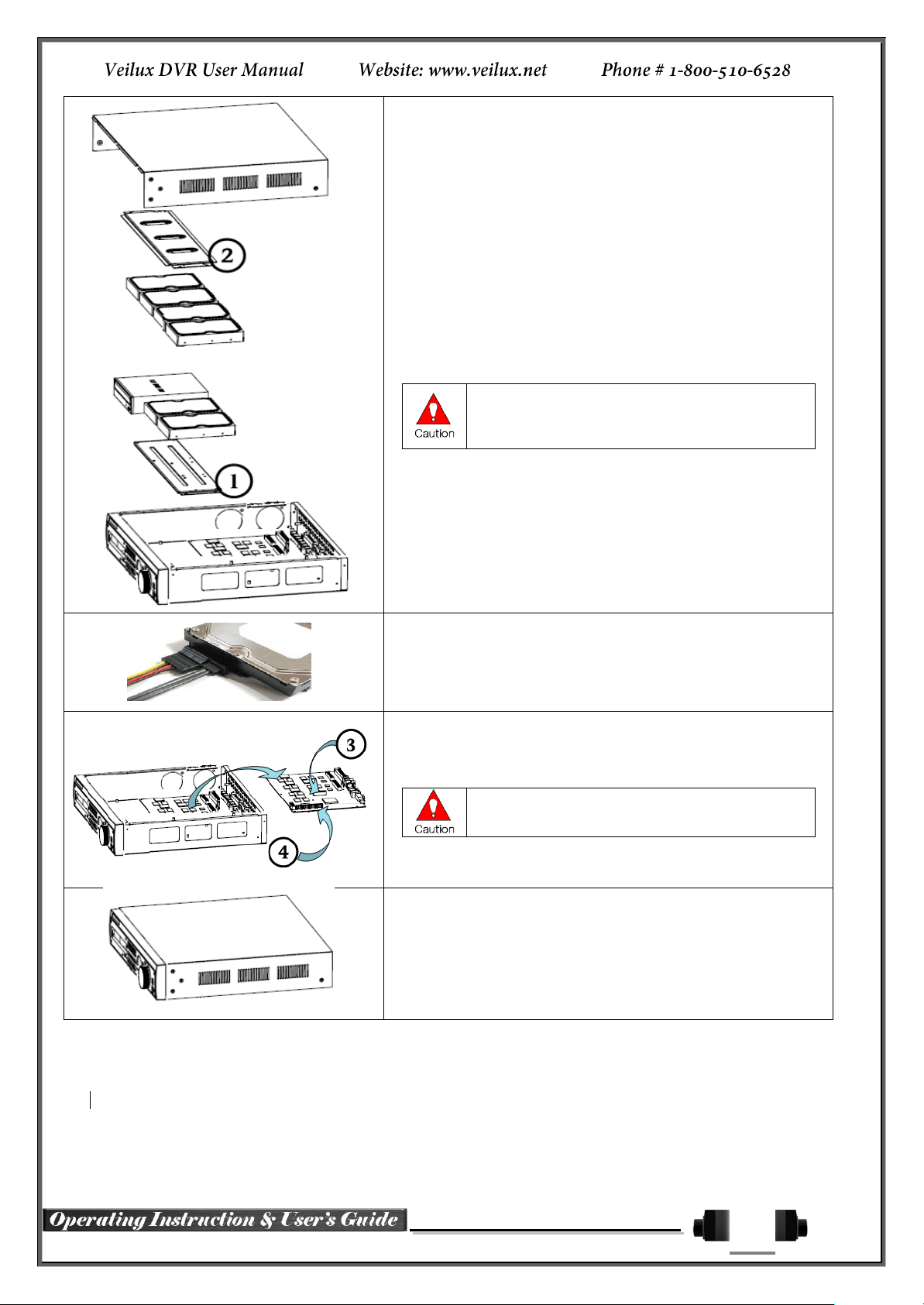
※ Step 1
1) Using a screw driver, unscrew and take off the top case of the
product.
1) Normal termination of the system and fully unplugged power
code are required before conducting HDD installation.
2) After installing HDD, Do not connect to power supply with
the top case opened. The top case must be covered before
usage.
※ Step 2
2) Using a screw driver, unscrew the fixing bolt of the top HDD bay
② and separate the top HDD bay② from the body.
3) Using a screw driver, unscrew the fixing bolt of the bottom HDD
bay① and separate the bottom HDD bay① from the body.
1-4 DVR Operation Setup
1-1 HD1 series Storage Installation
The recommended HDD specification are shown below
18
※ Step 3
4) Align screw holes and screw and fix HDD onto the bottom HDD
bay①.
5) Align screw holes and screw and fix HDD onto the top HDD bay②
6) By reversing Step 2, combine both top② and bottom① HDD bay
with the body.
1) SVR-1648D1 model can hold HDD up to 3ea, H
model can hold HDD up to 6ea
2) HDD power and data terminal should face the
inner direction.
※ Step 4
7) Connect the power cable and data cable to HDD.
※ Step 5
8) HD1-1648 T model provide 2ea power terminals(③). Connect the
power cable into the power terminal(③).
※ HD1-1648 H model has a different type of SATA
power cable.
9) Connect the HDD data cable into the mainboard data cable
connector(④).
※ Step 6
10) Reassemble the top case by reversing 1) to finalizing HDD
installation.
19
VRHD-8-4SDI-DVD (HD-SDI Hybrid)
VRHD-4-4SDI-DVD
System
Reliable Standalone DVR
Channel type
4 BNC - HD-SDI, 4 BNC - SD
Analog
4 BNC - HD-SDI
OS
Embedded Linux - Built in Flash Memory
Video Input
8 BNC
4 BNC
Video
output
Monitor
1 VGA, 1 HDMI, 1 BNC
1 VGA, 1 HDMI
Spot
1 BNC
N/A
Audio Input
Line Input : 4 RCA
Audio Output
Line Output : 1 RCA
Compression Format
[Video: Standard H.264)] / [Audio: G.711]
Recording Speed
Max. 45fps@720p
Max.20fps@1080p
45fps@720p
Recording Resolution
Max. 720p
Max. 1080p
Recording Mode
Automatic, Continuous, Manual, Events(Sensor and Motion, Sound)/Schedule
Recording
Storage
Internal
Max. 2HDD, Max. 4TB, 1 DVD
External
1 eSATA
Video Output Resolution
HDMI : Full HD(1080p), HD(1080i), WSXGA,SXGA
VGA : WSXGA (1680x1050), SXGA(1280 x 1024),
TV : SDTV(720 x 480/576) (Only for MH2-804)
Sensor Input
4 Sensors
Relay/TTL Output
[1ea NC/NO]
Backup & Copy Access
DVD-RW, USB2.0, Network
Network Access
Various Network Interface
(Ethernet 10/100/1000, ADSL, Cable modem)
PTZ Access
2ea of RS485
System Operation &
Adjustment
Front Button, Mouse, IR Remote Controller, Keyboard Controller, Network
System Upgrade
USB2.0 Memory Stick, Network
Network
System Automation (Controlled by VMS)
NTP Supported
VMS / WEB Brower / PDA / Smart Phone
Others
18 Languages Supported, Automatic E-mail
Power [12V/5A] / Max. Power Consumption [60W] /
Operating Temperature [5 ~ 40℃]
Weight without HDD [4kg] / Dimension [430 ⅹ 86 ⅹ 270mm]
Chapter 2. VRDH-*-4SDI / VRHD-*4SDI-DVD
2-1 Introduction of the VRHD*-4SDI / VRHD-*-4SDI-DVD
VRHD-****4SDI-DVD series Major Features
20
VRHD-8-4SDI
VRHD-4-4SDI
System
Reliable Standalone DVR
Channel type
4 BNC - HD-SDI
4 BNC - SD Analog
4 BNC - HD-SDI
OS
Embedded Linux - Built in Flash Memory
Video Input
8 BNC
4 BNC
Video
output
Monitor
1 VGA, 1 HDMI, 1 BNC
1 VGA, 1 HDMI
Spot
1 BNC
N/A
Audio Input
Line Input : 4 RCA
Audio Output
Line Output : 1 RCA
Compression Format
[Video: Standard H.264)] / [Audio: G.711]
Recording Speed
Max. 45fps@720p
Max.20fps@1080p
45fps@720p
Recording Resolution
Max. 720p
Max. 1080p
Recording Mode
Automatic, Continuous, Manual, Events(Sensor and Motion, Sound)/Schedule
Recording
Storage
Internal
[Internal: Max. 2HDD, Max. 4TB]
External
1 eSATA
Video Output
Resolution
HDMI : Full HD(1080p), HD(1080i), WSXGA,SXGA
VGA : WSXGA (1680x1050), SXGA(1280 x 1024),
TV : SDTV(720 x 480/576) (Only for SH2-804)
Sensor Input
4 Sensors
Relay/TTL Output
[1ea NC/NO]
Backup & Copy
Access
USB2.0, Network
Network Access
Various Network Interface
(Ethernet 10/100/1000, ADSL, Cable modem)
PTZ Access
2ea of RS485
System Operation &
Adjustment
Front Button, Mouse, IR Remote Controller, Keyboard Controller, Network
System Upgrade
USB2.0 Memory Stick, Network
Network
System Automation (Controlled by VMS)
NTP Supported
VMS / WEB Brower / PDA / Smart Phone
Others
18Languages Supported, Automatic E-mail
Power [12V/5A] / Max. Power Consumption[40W] /
Operating Temperature [5 ~ 40℃]
Weight without HDD [3kg] / Dimension [340 ⅹ 58 ⅹ 300mm]
VRHD****4SDI series Major Features
21
VRDH-4-4SDI-DVD /
VRHD-8-4SDI-DVD
VRHD-4-4SDI
VRHD-8-4SDI
DVD
OK
NO
Front Button
29 buttons
14 Buttons
USB port
Front Panel
Right side of the front panel
Dimension
19’ RACK SIZE
COMPACT SIZE
About the Product
As a digital image monitoring equipment that can display images inputted from up to 16/8 cameras, VR****4SDI-DVD VR-*****-4SDI -Series digitally records high-quality images using various video recording modes and
displays them as clean quality images.
For users’ convenience, front panel button, remote controller, and mouse are provided. Powerful network
functions including remote monitoring and remote system setup modification are also supported.
Differences between VRHD****-4SDI-DVD / VRHD***-4SDI
series
Components
Please check the components after unpacking the product.
- Remote controller
- DVD (VMS, VMS Manual DVR user manual, how to video, our products)
- AAA 1.5V Batteries 2es
- Adapter (12VDC/ 5A)
- Rack Mounting Handle (Only VRHD-****-4SDI-DVD series)
22
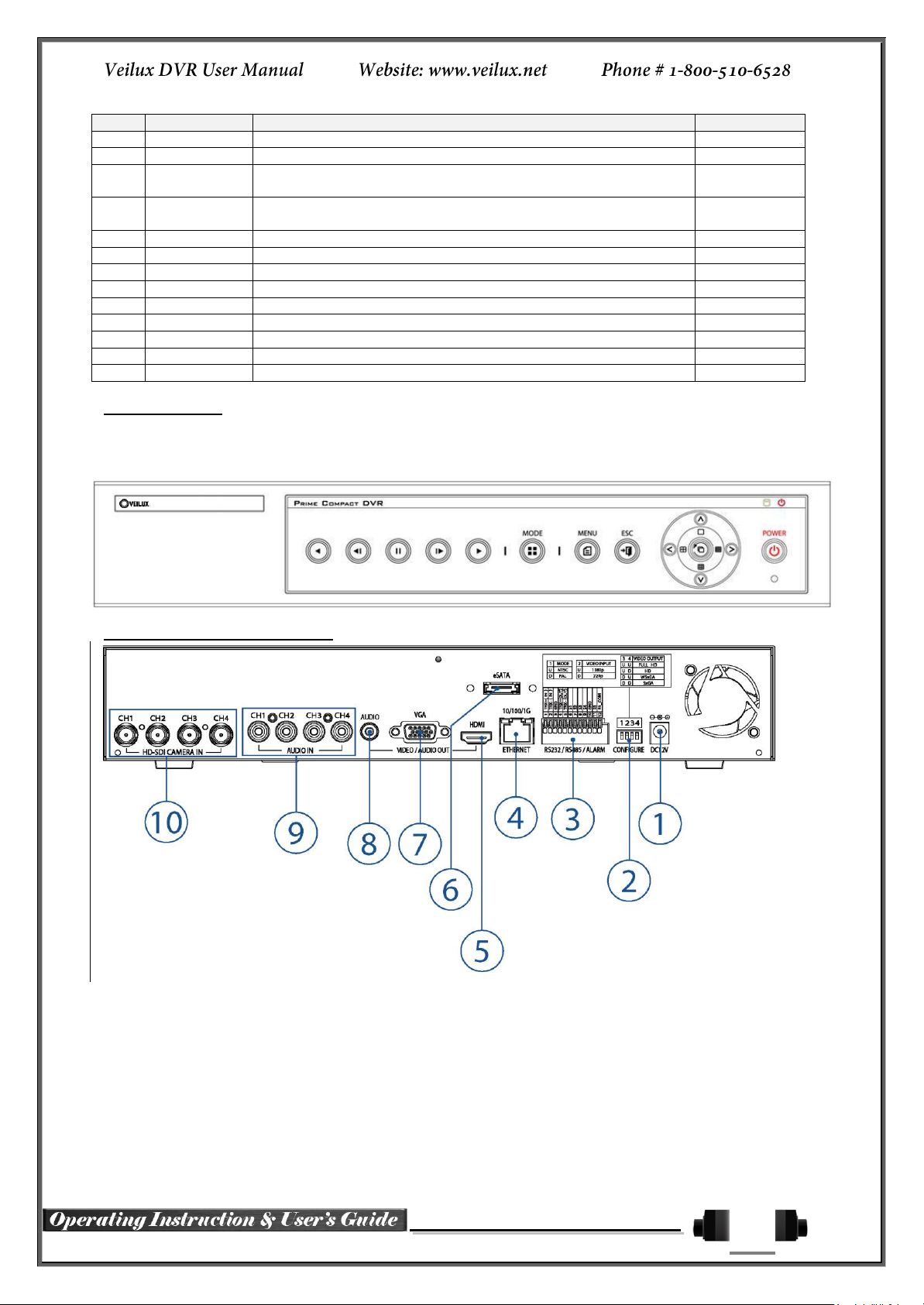
VRHD-***4SDI-DVD Series Name and Features of each part
VRHD series has buttons on the front panel and various interfaces on the rear panel. Also, it has rack handles
of the left and right side for the convenience of the standard rack installation.
SVR-1648, SVR-824, SVR-412 Front Panel
VRHD-4-SDI-DVD Channel Rear Panel
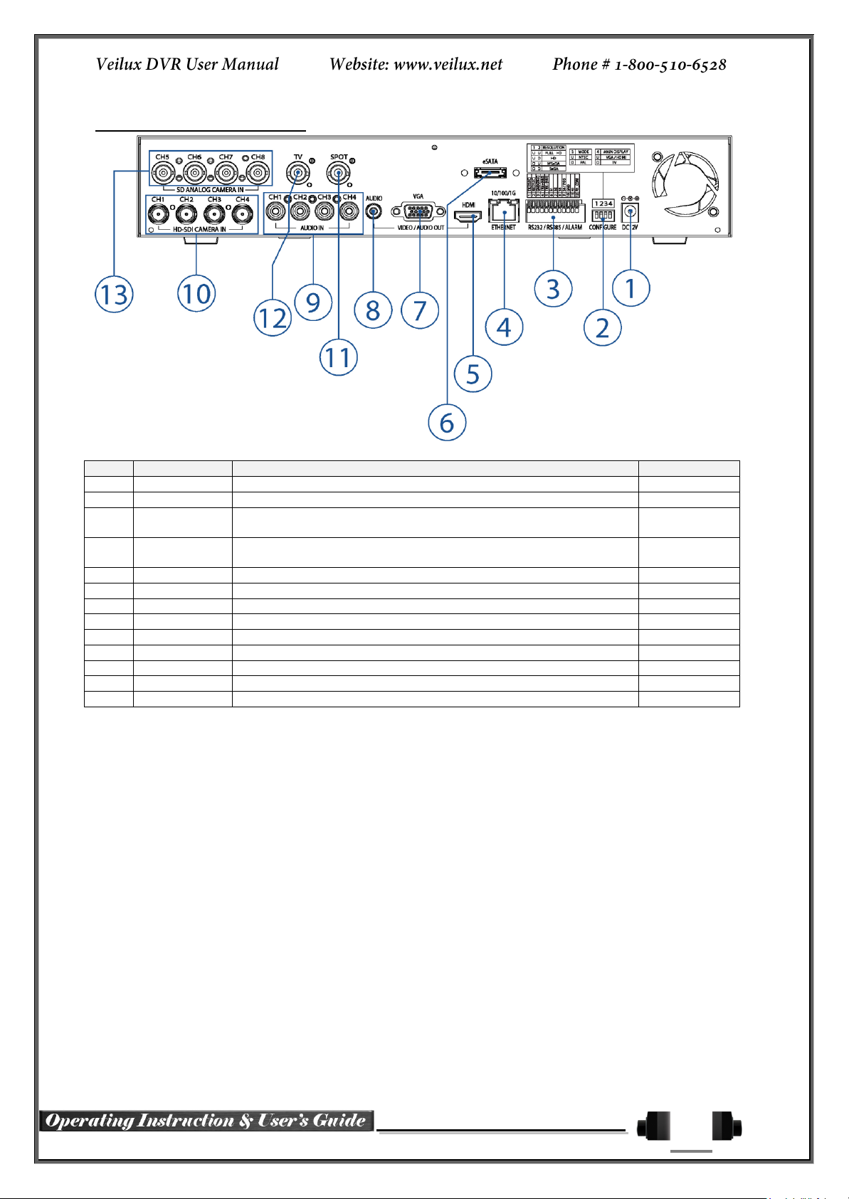
VRHD-8-4SDI-DVD Channel Rear Panel
23
No.
Name
Function
Type
1
DC-IN Power
100~240V, 50/60 Hz, 5A
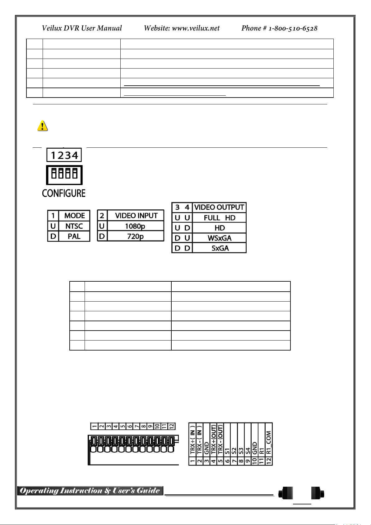
2
CONFIGURE
Select the type of video input and output
Switch
3
RS485
DIO
PTZ Camera Control Connection
Sensor/ Relay Connection
Termnal Block
4
Ethernet
Network connection(ADSL, Cable Modem, Ethernet 10/100/1000
Base-T)
RJ-45
5
HDMI
HDMI Video output
HDMI type-C
6
eSATA
External SATA Storage
eSATA
7
VGA-OUT
VGA Monitor or LCD Monitor connection
D-SUB 15P
8
AUDIO OUT
Audio output connection (Line Only Output)
RCA
9
AUDIO IN
Audio input connection (Line Only Input)
RCA
10
CAMERA IN
HD-SDI Camera connection
BNC
11
SPOT
SPOT Video output / CCTV monitor connection
BNC
12
TV
CCTV Monitor Connection(Divided Screen)
BNC
13
CAMERA IN
SD Camera connection
BNC
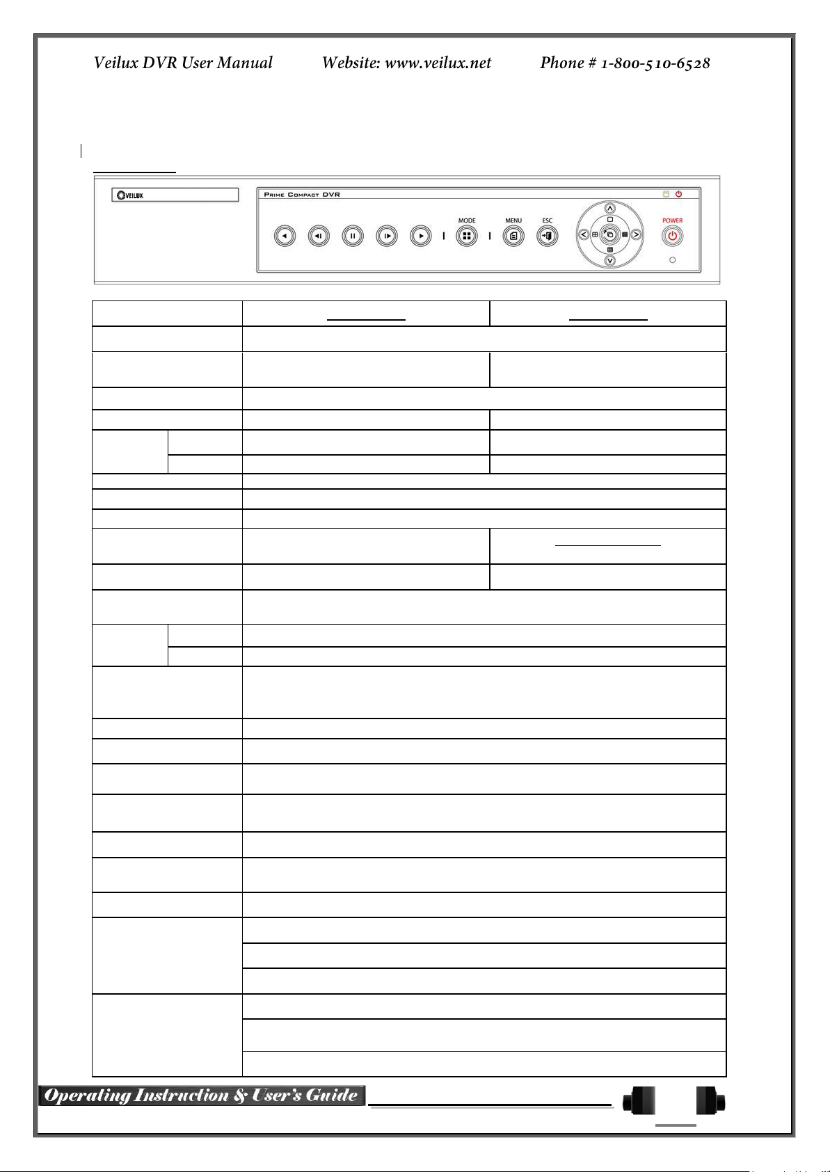
VRHD-*****-4SDI Series Front Panel
SH2 series has the buttons which is simple and easy and the various interfaces on the rear panel.
SH2 Series Front Panel
VRHD-4-4SDI Channel Rear Panel
24
No.
Name
Function
Type
1
DC-IN Power
100~240V, 50/60 Hz, 3.5A
2
CONFIGURE
Select the type of video input and output
Switch
3
RS485
DIO
PTZ Camera Control Connection
Sensor/ Relay Connection
Termnal Block
4
Ethernet
Network Connection (ADSL, Cable Modem, Ethernet 10/100/1000
Base-T)
RJ-45
5
HDMI
HDMI Video output
HDMI type-C
6
eSATA
External SATA Storage
eSATA
7
VGA-OUT
VGA Monitor or LCD Monitor connection
D-SUB 15P
8
AUDIO OUT
Audio output connection (Line Only Output)
RCA
9
AUDIO IN
Audio input connection (Line Only Input)
RCA
10
CAMERA IN
HD-SDI Camera connection
BNC
11
SPOT
SPOT Video output / CCTV monitor connection
BNC
12
TV
CCTV Monitor Connection(Divided Screen)
BNC
13
CAMERA IN
SD Camera connection
BNC
VRHD-8-4SDI Channel Rear Panel
25
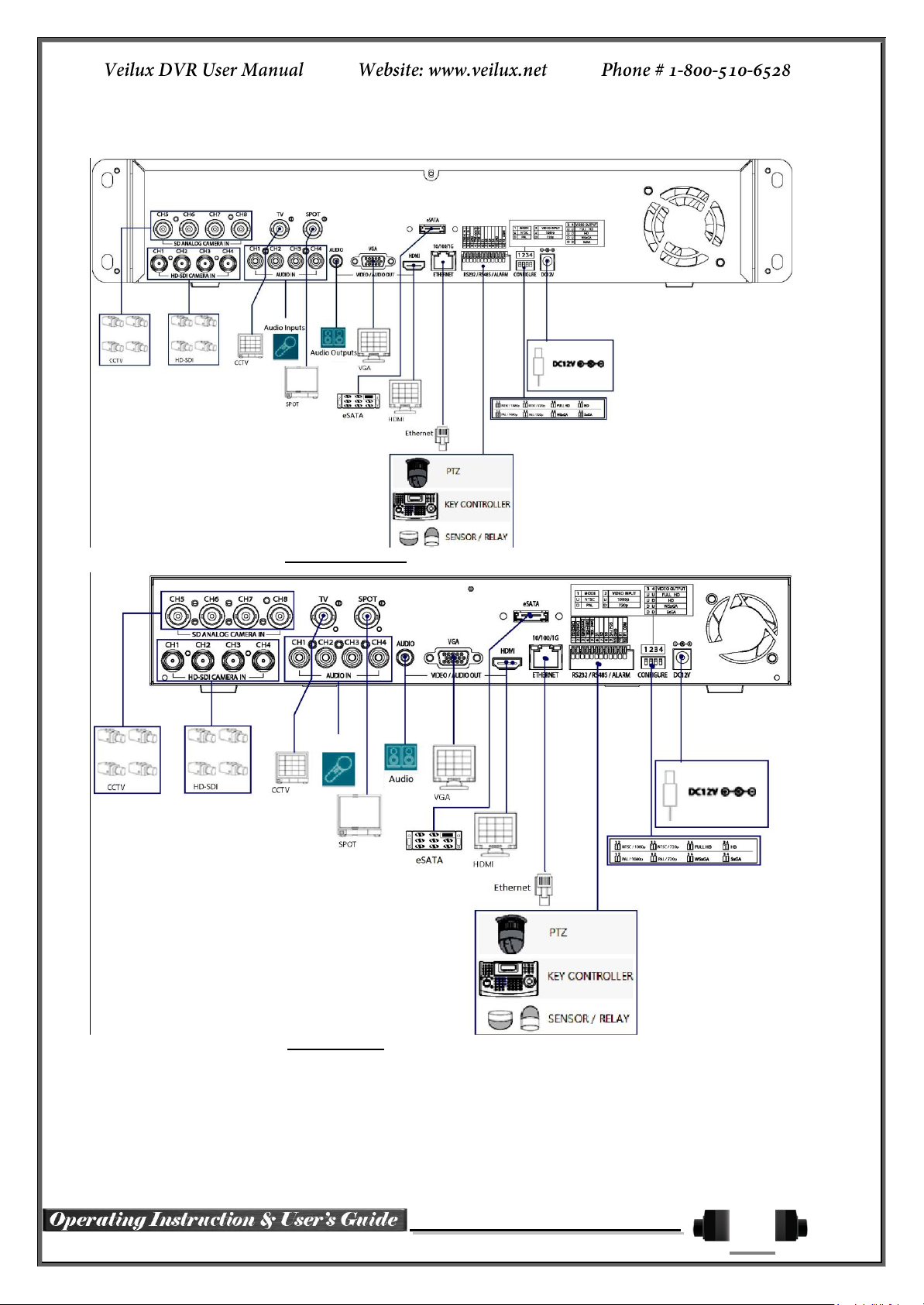
2-2 Installation and Connection
[Figure 2-1. VRHD-8-4SDI-DVD Basic Connection and Device Connection]
[Figure 2-2. SVR-8-4SDI Basic Connection and Device Connection]
By referring to above [Figure 2-1] and [Figure 2-2], Connect the CCTV camera, CCTV monitor (or VGA
monitor), and USB mouse to the DVR and set up CONFIG SWITCH.
26
Connecting Device
DVR Terminal
1
CCTV camera
Rear Panel Video Input
2
CCTV monitor
Rear Panel TV
3
VGA Monitor / LCD Monitor
Rear Panel VGA-OUT
4
Mouse
VRHD-******-4DSI-DVD: on front panel / VRDH-*****-4SDI series: on right side
5
CONFIG SWITCH
Rear Panel NTSC/PAL or VGA/TV Setup
Refer to the CONFIG SWITCH description as below.
1. The input video type must be either NTSC or PAL; these two types must not be used together.
2. Select the input video format (NTSC/PAL) using the CONFIG switch on the rear side of the product.
3. Should select one between 1080p and 720p for input resolution. These two types must not be used
together. 8Ch DVR is setup 720P regardless of video input.
Connecting Device
DVR Terminal
1
SPOT Monitor(CCTV Monitor)
Rear Panel SPOT
2
Mike / Speaker
Rear Panel Audio Input / Audio Output
3
LAN Cable
Rear Panel Ethernet
4
PTZ Camera
Rear Panel Terminal Block
5
Sensor / Relay / TTL OUTPUT
Rear Panel Terminal Block)
6
Key controller
Rear Panel Terminal Block
Connection of Other Devices
Connect the PTZ controller cable, audio in/output, network and sensors as below.
1) SPOT Monitor
Connect Spot Monitor to the spot connector on the rear panel.
2) Audio In/Output
Audio supports 4 inputs and 1 output.
3) Terminal Block
Terminal Block on the rear panel is for the connections of PTZ / Sensor / Relay.

27
[Figure 2-3. Terminal Block Description]
PTZ Camera may not be working properly if GND is not connected.
Sensor has the type of NC (Normal Close) and NO (Normal Open).
For Setup {Menu} {Setup} {Action} {Event} {Sensor Type}
NC (Normal Close): Normally closed; opens when a signal is received.
NO (Normal Open): Normally opened: closed when a signal is received.
Relay has the type of NC (Normal Close) and NO (Normal Open).
For Setup {Menu} {Setup} {Action} {Alarm} {Relay Type}
NC (Normal Close) : Normally closed; opens when a signal is received.
NO (Normal Open) : Normally opened: closed when a signal is received.
4) PTZ Camera/Keyboard Controller
Connect PTZ camera to TRX+ (No.4) and TRX- (No.5) and GND (No.10). You may refer to APPENDIX for
supported PTZ camera list in this manual. Keyboard Controller has same connection way of PTZ camera.
5) Sensor/Relay
Connect Sensor/Relay to Terminal Block directly.
(1) Sensor Connection
② Connect Sensors to the Terminal Block S1 ~ S4.
③ Each input terminal may be connected regardless of the channel number.
(2) Relay Connection
④ Outputs alarm signals to external devices such as siren by relaying them to these external devices.
⑤ Connect Relay to R1 of Terminal Block (TB1).
 Loading...