

Page 1
Operating Instruction
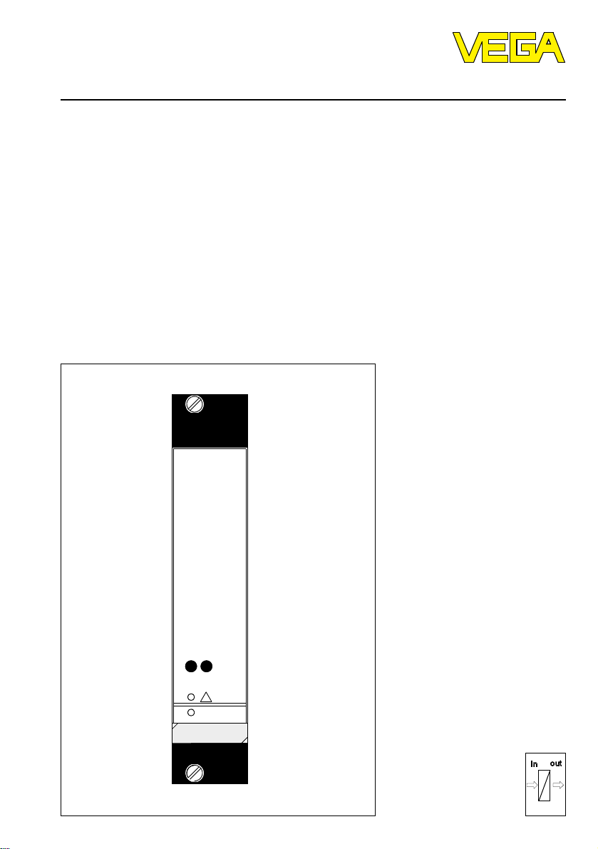
VEGATRENN 544 Ex
Level and Pressure
!
on
VEGATRENN
CONNECT
544 Ex
out
in
Page 2

Contents
Safety information ........................................................................................ 2
1 Product description
1.1 Function and configuration ................................................................. 3
1.2 Application .......................................................................................... 4
1.3 Approval ............................................................................................. 4
1.4 Technical data ..................................................................................... 5
1.5 Dimensions ......................................................................................... 7
2 Mounting
2.1 Mounting versions............................................................................... 8
2.2 Instrument address ............................................................................. 9
3 Electrical connection ......................................................................... 10
4 Set-up
4.1 Indicating and operating elements ................................................... 10
4.2 Adjustment via PC ............................................................................ 11
4.3 Set-up sequence .............................................................................. 11
Contents
5 Diagnosis
5.1 Maintenance ..................................................................................... 11
5.2 Repair ............................................................................................... 11
5.3 Fault signal........................................................................................ 11
Safety information
The described module must only be inserted and operated as described in this operating instruction. Please
note that other action can cause damage for which VEGA
does not take responsibility.
2 VEGATRENN 544 Ex
Page 3
Product description
1 Product description
1.1 Function and configuration
VEGATRENN 544 Ex Ex-separator powers via an
intrinsically safe circuit the respectively connected
sensor and processes in addition the measured data
of the sensor.
Function
The measured data of 4 ... 20 mA directly adjusted on
the sensor are processed in VEGATRENN 544 Ex into
a current and volt output as well as in a digital signal
output (DISBUS).
VEGATRENN 544 Ex is equipped with sockets for
connection of a VEGACONNECT connection cable. A
communication to a PC can be provided via
VEGACONNECT.
If necessary this combination enables in a very simple
way a parameter adjustment of the processing or
outputs or editing of linearization curves.
Configuration
VEGATRENN 544 Ex is mechanically designed in 19"technology (width 5 TE = 24,5 mm).
Electronically the instrument is microcomputer controlled and consists function technically out of software
components, see following sketch.
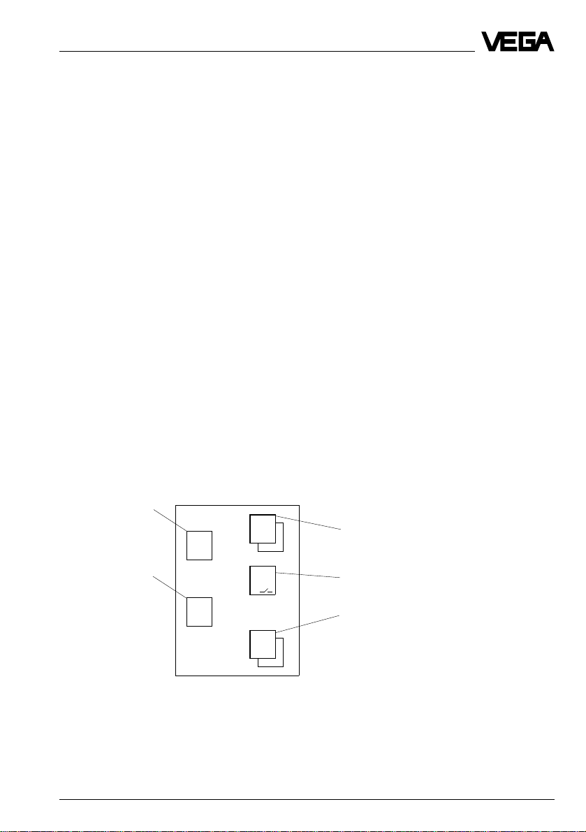
Sketch
Function component
- Measuring point MST
- 4 … 20 mA
neutral parameter
- Sensor
Input component
- Sensor 4 … 20 mA
FB
1
EB
1
VEGATRENN 544 Ex 3
AB
mA
V
AB
AB
PC
DIS
Output component
Current output 0 … 20 mA
Volt output 0 … 10 V
Fail safe relay
Digital output
- PC-/DCS-output
- DISBUS-output
Page 4
A
A
A
1.2 Application
Application: Level
Sensor: Range 4 … 20 mA
Hydrostatic pressure transmitter
Process pressure transmitter
Differential pressure transmitter
Parameter: MST1 4 … 20 mA neutral parameter
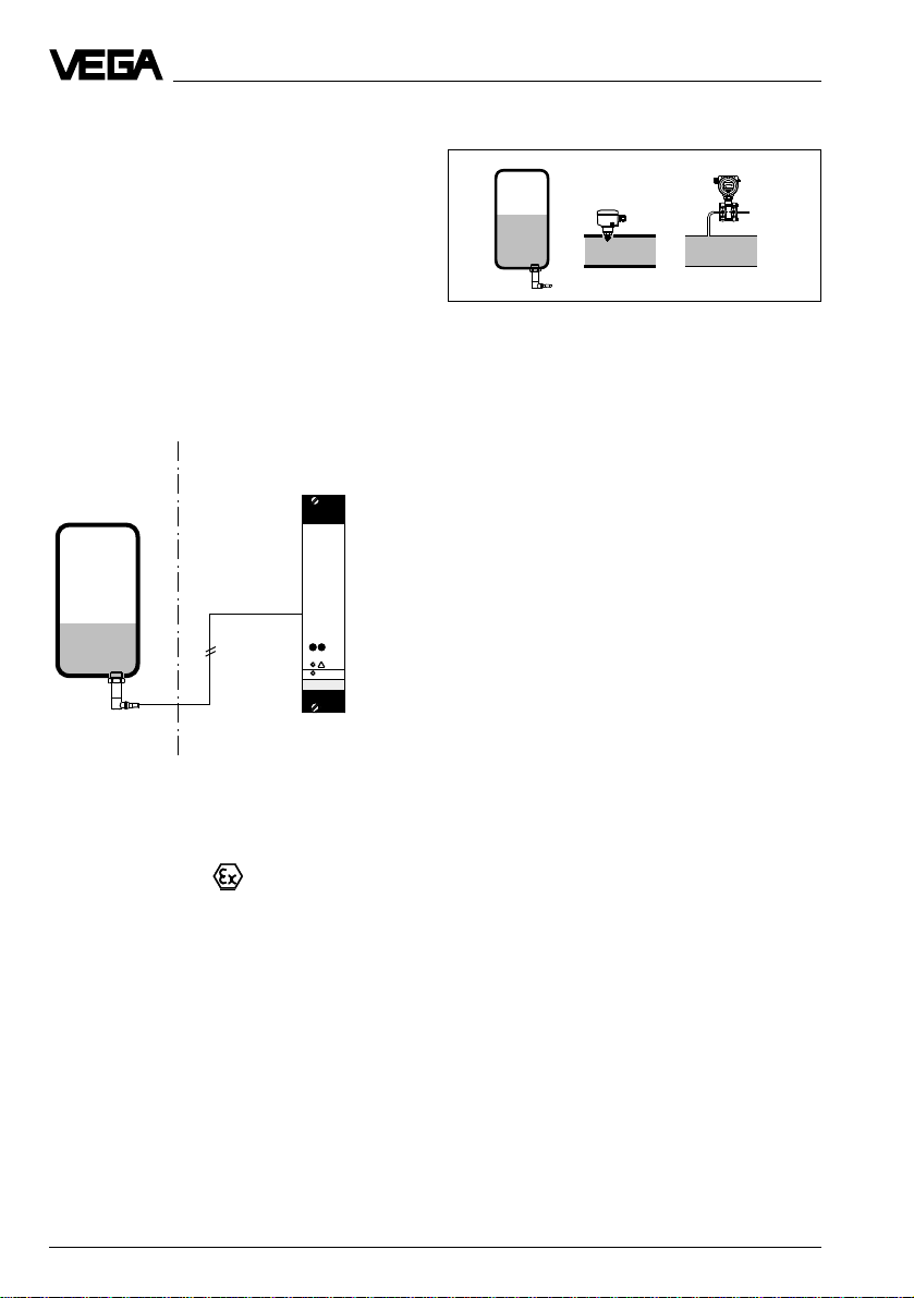
Exemplary application
Product description
Fig. 1.1 Level measurement
Ex-area
Ex-Sensor
4 … 20 mA
Not-Ex-area
intrinsically safe
circuit
VEGATRENN 544 Ex
Measuring point MST processing
- Current output
- Volt output
- DISBUS
- Fail safe relay
Parameter
- 4 … 20 mA neutral parameter
1.3 Approval
Ex-approval
For hazardous areas, certification to CENELEC defined in conformity certificate PTB-no. Ex-95.D.2145 X.
4 VEGATRENN 544 Ex
Page 5

Product description
1.4 Technical data
Power supply
Operating voltage U
Power consumption appr. 7 VA or appr. 5 W
Measuring data input
Number 1 input
Kind of input active two-wire input, analogue
Range 4 … 20 mA
Sensor hydrostatic pressure transmitter,
Voltage at 4 mA ca. 18 V DC, at 20 mA appr. 15 V DC
Current limitation at appr. 26 mA, shortcircuit proof
Detection line break < 2 mA
Detection shortcircuit > 23 mA
Connection line 2-wire (standard line)
Resistance per conductor max. 35 Ω
Resolution 1 µA
Linearity error 0,025 % at 4 … 20 mA
Temperature error 0,04 %/10 K at 4 … 20 mA
Measuring data input, Ex-technical data
Classification [EEx ia] IIC, [EEx ia] IIB, [EEx ib] IIC or [EEx ib] IIB
Max. values
- Voltage UO = 20 V
- Current I
- Power P
Characteristics linear
Effective inner inductance L
Effective inner capacitance C
i
i
Max. permissible outer inductance LO (mH) 0,5 1 1,5 2 2 9
Max. permissible outer capacitance CO (nF) 97 78 68 486 200 1000
= 24 V AC (20 … 53 V), 50/60 Hz
nenn
= 24 V DC (20 … 72 V)
process pressure transmitter,
differential pressure transmitter
= 128 mA
O
= 640 mW
O
negligible
negligible
EEx ia IIC EEx ia IIB EEx ib IIC EEx ib IIB
The intrinsically safe circuits are reliably separated from the not-intrinsically safe circuits up to a peak value of
the nominal voltage of 375 V.
The max. voltage on the not-intrinsically safe circuits must not exceed 250 V
in case of failure.
eff
Current output
Number 1 output
Function analogue output of processing results
Range 0/4 … 20 mA
Load max. 500 Ω
Resolution 0,05 % of range
Linearity error 0,05 % of range
Temperature error 0,05 %/10 k of range
>>
VEGATRENN 544 Ex 5
Page 6

Product description
Voltage output
Number 1 output
Function analogue output of processing results
Range 0/2 … 10 V
Current max. 1 mA
Resolution 0,05 % of range
Linearity error 0,05 % of range
Temperature error 0,06 %/10 k of range
Fail safe relay
Contact 1 floating spdt
AgNiO and hard gold plated
Turn-on voltage min. 10 mV DC
max. 250 V AC/DC
Switching current min. 10 µA
max. 3 A AC, 1 A DC
Breaking capacity max. 500 VA, 54 W
DISBUS-output
Function digital transmission of processing results and
system informations to VEGADIS 174 or
VEGACOM 557
Connection line 2-wire (screened)
Line length max. 1000 m
Indicating element
LED in front plate green on: operating voltage on
red: fault signal
Ambient conditions
Permissible ambient temperature -20°C … +60°C
Storage and transport temperature -40°C … +80°C
Electrical connection
Multiple plug component to DIN 41 612, series F, 36-pole triple row d, b, z
(partly equipped)
Carrier BGT 596 (Ex) connection to appropriate module
Housing type 505 connection to screw terminals (max. 2,5 mm
Electrical protective measures
Protection
- not mounted IP 00
- mounted in carrier BGT 596 Ex.M
front completely equipped: IP 40
upper and lower side: IP 20
wiring side: IP 00
- mounted into housing type 505
- terminal side IP 20
- housing in general IP 30
Protection class II (in housing type 505)
Overvoltage category II
2
)
>>
6 VEGATRENN 544 Ex
Page 7

Product description
Electrical separating measures
Reliable separation acc. to VDE 0106,
part 1 between power supply, measuring data input
- Limit voltage 250 V
- Isolation resistance 2,3 kV
Common reference potential at voltage/current output
Mechanical data
Series module unit for carrier BGT 596 Ex.M
or housing type 505
Dimensions unassembled W = 25, 4 mm (5 TE), H = 128,4 mm, D = 162 mm
CE-approval, conformity judgement
VEGATRENN 544 Ex signal conditioning instrument meets the protective regulations of EMVG (89/336/EWG)
and NSR (73/23/EWG). The conformity has been judged acc. to the following standards by means of a typical
configuration:
EMVG Emission EN 50 081 - 2: 1993
Susceptibility EN 50 082 - 2: 1995
NSR EN 61 010 - 1: 1993
1.5 Dimensions
Circuit board 100 x 160 x 1,5
European size Multiple plug
5 TE
128,4
CONNECT
on
544 Ex
25
14,5
100
VEGATRENN
Ser.No.12345678
9
3
162
VEGATRENN 544 Ex 7
Page 8

2 Mounting
2.1 Mounting versions
VEGATRENN 544 Ex separator can be either mounted
with a module in a carrier BGT 596 Ex.M or in a single
housing type 505.
Module Ex
Multipoint connector DIN 41 612, series F, 33-pole (d,
b, z) with coded pins, Ex-separating chamber and
mounting material for mounting in carrier
BGT 596 Ex.M.
Single housing
Plastic housing type 505 for single mounting.
Mounting carrier
Mount the respective module (Ex-version) in the
carrier. Wire the connections of the multipoint connector according to the wiring plan on the following
pages.
The multipoint connector is available as follows:
- Wire-Wrap standard connection 1,0 x 1,0 mm
- plug connection 2,8 x 0,8 mm
- Termi-Point Standard connection 1,6 x 0,8 mm
- soldering connection
- screw terminals 2 x 0,5 mm
For further information concerning mounting see
operating instruction of the carrier.
Mounting single housing
You can either screw the housing socket directly to the
mounting plate or plug on a carrier rail (TS 35 x 7,5
acc. to EN 50 022 or TS 32 acc. to EN 50 035). Connect the terminals according to the wiring plan on the
following pages. For further information to mounting
see operating instruction of the housing.
Transparent cover
To protect the housing against unauthorized operation,
the front plate of VEGATRENN can be provided with a
lockable transparent cover.
2
Mounting
Coding
To avoid interchanging of the various signal conditioning instruments, the multipoint connector of the carrier
or the housing is provided with pins and the multiple
plug of VEGATRENN with holes (mechanical coding).
An Ex-coding with fixed coded pin ensures that not-Ex
and Ex-instruments are not interchanged.
An instrument coding ensures that the various signal
conditioning instruments are not interchanged. The
respective coded pins are attached to each module or
housing. Provide the multipoint connector with these
coded pins acc. to the following schedule and figure.
Instrument Ex-
coding coding
VEGAMET 514 D a5 / c5
VEGAMET 514 D Ex a5 / c5 c23
VEGAMET 514 VD a7 / c5
Fig. 2.1 Coding schedule
Instrument coding Function coding
z b d
544
a1
a c
o 1 o
o 3 o
o 5 o
o 7 o
o 9 o
o11o
o13o
o15o
o17o
o19o
o21o
o23o
o25o
o27o
o29o
o31o
c5
c23
VEGATRENN
Ex-coding
Fig. 2.2 Module coding, VEGATRENN
8 VEGATRENN 544 Ex
Page 9

Mounting
Ex-version
Note!
VEGATRENN must be generally mounted outside
hazardous areas or special Ex-protective measures
must be taken.
Ex-separating chamber
To ensure suffcient "air and creeping distances", an
Ex-separating chamber must be mounted to the
connections of VEGATRENN. Loop the wires through
the Ex-separating chamber and connect them. Fasten
the Ex-separating chamber with the lower screw.
Observe the operating instruction of carrier
BGT 596 Ex.M.
Protection for Ex-applications
In Ex-applications a protection of IP 20 must be kept.
Cover the spaces or not used modules from the front
by appropriate blind covers.
Mounting in carriers
If you mount your VEGATRENN with Ex-approval in a
carrier, you have to use a VEGA-Ex-module. Keep a
distance of at least 10 mm (2 TE) to modules of other
manufacturers. If you want to mount the VEGATRENN
in the extreme left position in the carrier, you have to
mount a blind cover of at least 20 mm (4 TE) in front of
the module of the instrument.
2.2 Instrument address
Adjust on the respective switch on the circuit board
the instrument address. Address range 1 … 15. Observe that no double coordination is made. Factory
setting = instrument address 0
8
9
7
A
6
5
4
33
E
2
F
1
0
corresp.
B
C
D
10
11
12
13
14
15
on
VEGATRENN
544 Ex
Blind cover
VEGATRENN 544 Ex 9
Page 10

3 Electrical connection
Electrical connection / Set-up
VEGA TRENN 544 Ex
d b z
+-
10
12
16
18
20
22
24
28
30
32
2
6
+
+
+
-
Fail safe relay
+
DISBUS-output
-
Supply
voltage
Current output
Voltage output
L (+)
N (-)
+
-
Sensor
4 Set-up
4.1 Indicating and operating elements
Ex-version
For connection of Ex-certified instruments observe the
instructions in the attached legal documents as well as
in the valid mounting instructions. Note that the Exseparating chamber is mounted on the multipoint
connector. Always loop the wires through the Exseparating chamber. Observe the operating instruction
of the carrier BGT 596 Ex.M and the Ex-instructions.
1
8
1 Fixing screw lockable
2 Connection for VEGACONNECT
connection cable
3 LED fault signal
4 LED supply voltage
5 Ledge
7
6
6 Multiple plug with wiring plan
7 Position of the switch for adjustment
of the instrument address
8 Transparent cover
2
3
4
5
1
CONNECT
!
on
VEGATRENN
544 Ex
Ser.No.12345678
Fig. 4.1
10 VEGATRENN 544 Ex
Page 11

Set-up / Diagnosis
5 Diagnosis
4.2 Adjustment via PC
Parameter adjustment and editing
- exclusively by means of a PC, provided
with VVO-Software (VEGA Visual Operating) and a VEGACONNECT connection cable
CONNECT
!
on
VEGATRENN
Ser.No.12345678
544 Ex
VEGACONNECT
connection cable
PC with VVO-Software
4.3 Set-up sequence
- Prepare electrical connection
- Adjust sensor (4 … 20 mA)
- Adjust instrument address
if necessary via PC and VEGACONNECT
5.1 Maintenance
The instrument is maintenance-free.
5.2 Repair
Due to safety and guarantee reasons repair work
beside the wiring must only be made by VEGA-staff.
In case of a defect please return the respective instrument with a short description of the error to our repair
department.
5.3 Fault signal
The instrument and the connected sensor are permanently monitored during operation.
In case of failure the fail safe relay de-energizes, the
failure LED lights and the outputs react according to
the given control reaction.
In case of failure information texts can be displayed on
the PC as described under "4.2 Adjustment via PC".
Parameter adjustment of the processing
- scaling (allocation of a multiplication factor)
- linearization
- integration time
Parameter adjustment of the outputs
- relation and range of the current output
- failure reaction of the current output
- relation and range of the Volt output
- failure reaction of the Volt output
- relation and unit of the PC/DCS-output
- relation and unit of the DISBUS-output
Additional functions
- parameter adjustment of the password
- edit linearization curve 1 … 3
VEGATRENN 544 Ex 11
Page 12

VEGA Grieshaber KG
Am Hohenstein 113
D-77761 Schiltach
Phone (0 78 36) 50 - 0
Fax (0 78 36) 50 - 201
Fax (0 78 36) 50 - 203
ISO 9001
12 VEGATRENN 544 Ex
Technical data subject to alterations 2.20 174 / April '96
 Loading...