

Page 1

Model TRA223
Tone Remote Panel
Technical Manual
August 29, 2002 P.N. 803570
Page 2

Page 3

Tone Remote 1
Table of Contents
1 General .................................................................................... 2
1.1 Accessories............................................................................................................................ 2
2 Installation............................................................................... 3
2.1 Power Supply........................................................................................................................ 3
2.2 Line Connection.................................................................................................................... 3
2.2.1 Full Duplex.................................................................................................................... 3
2.3 Radio Connection.................................................................................................................. 4
2.3.1 TX Audio Connection.................................................................................................... 4
2.3.2 RX Audio Connection.................................................................................................... 4
2.3.3 TO-23 Balanced Transformer option............................................................................. 4
2.3.4 PTT Connection............................................................................................................. 4
2.3.5 Monitor Connection....................................................................................................... 4
2.3.6 RX Squelch.................................................................................................................... 4
3 Level Settings and Adjustments ............................................ 5
3.1 Line Receive Level............................................................................................................... 5
3.2 Radio TX Level..................................................................................................................... 5
3.3 Line TX Level....................................................................................................................... 5
3.4 Monitor Adjustments ............................................................................................................ 5
4 Theory of Operation ................................................................ 6
4.1 Voice Circuits ....................................................................................................................... 6
4.2 2175Hz Decoder Circuits...................................................................................................... 6
4.3 Logic Circuits........................................................................................................................ 6
4.4 Monitor Function Circuits..................................................................................................... 7
4.5 RX Squelch Function Circuits .............................................................................................. 7
5 Schematics and Parts Lists ................................................... 8
6 Pin out and Jumper Settings Quick Reference Table ........ 15
6.1 Adjustments ........................................................................................................................ 15
6.2 SW1 Dip-switch Positions .................................................................................................. 15
6.3 Radio Connections .............................................................................................................. 15
6.4 Line Connections ................................................................................................................ 15
6.5 DB25 Cable Color codes .................................................................................................... 16
7 Warranty, Service, Repair, and Comments......................... 17
8 TRA223 Specifications ......................................................... 18
Page 4

2 Vega’s TRA223
1 General
The Vega TRA223 tone -remote adapter provides a reliable means of remotely controlling two-way-radio
base stations. The adapter can be used in conjunction with all Vega consoles, or other manufacturers'
(such as Motorola and MA-COM Ericsson GE) remote consoles, which use the industry-standard
sequential tone -keying format.
The TRA223 provides the following features:
PTT Relay
Monitor Relay
PTT and Monitor LED indications
Hardware gain control
Front panel test points and level setting potentiometers
Three monitor modes
The TRA223 is interconnected to the distant remote control console(s) by any voice-grade transmission
medium such as a microwave link, a leased telephone line, or a twisted-pair 600-ohm line. All TRA223s
are capable of decoding the PTT (push-to-talk/transmitter-on) tone sequence and the voice-plus-tone
signals during transmission. The tone portion of the voice-plus-tone signal is removed from the
transmitted voice. TRA223 are prepared for conversion from two-wire-line operation to four-wire-line
operation via a front panel DIP-Switch. In the four -wire mode, the panels are full duplex capable.
The TRA223 provides a “monitor” decode function that operates a relay used for turning off subaudibletone-decoder circuits in the radio receiver, allowing the console operator to monitor the channel for other
users before transmitting. (Required by FCC regulations on stations equipped with Continuous-ToneCoded-Squelch-Signaling)
Transient protection has been provided near all audio inputs and outputs. This is adequate for nearly all
transients.
The TRA223 line transformers are not designed to operate on lines carrying direct current. If a DC voltage
is on the line, isolate with external capacitors. If the line termination must conduct direct current, install a
600:600-ohm transformer designed for the current involved.
1.1 Accessories
The TRA223 can be ordered with several optional accessories.
TO-23 – Transformer isolation on transceiver interface
DSP223RACK – 1 unit high rack shelf to hold up to two TRA223 units
Power Supply
Page 5
Tone Remote 3
nel
Connector
2 Installation
POWER
GND
+12GND
RADIO
2.1 Power Supply
The TRA223 requires a 12 to
16 volt DC, 500ma, of clean
power. Two connectors are
provided to connect the unit to
power. The first is a 2.5mm
plug receptacle on the rear left
of the unit. The positive
terminal is the center conductor.
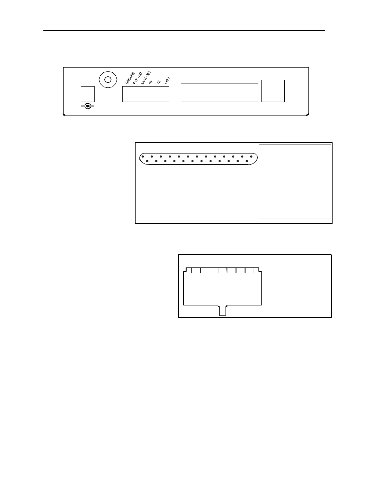
The second power connection
option is the DB25 connector.
Figure 1 shows the pin out of
this connector. Connect an
external 12 to 16 volt DC supply
with the positive connected to Pin 20 and the Ground connected to Pin 7.
DB25 Rear Pa
Figure 1
LINE
3-RX+
4-TX+
5-TX6-RX-
1-PTT NC 20-+POWER
14-PTT NO 82-PTT COM 2115-MON NC 93-MON NO 2216-MON COM 10-SQUELCH
4- 2317- 115- 24-RX+
18- 12-RX6- 25-TX+
19- 13-TX7-GROUND
2.2 Line Connection
The line connector Figure.2 is the right most
connector on the rear of the TRA223. Connect
the two-wire leased line to pins 4 and 5 of the
RJ-45 modular connector, making sure that SW1 position 1 is “ON” and position 2 is “OFF”.
For four-wire operation, move SW-1 position 1
is “OFF” and position 2 is “ON”, connect the
outgoing line to pins 4 and 5, and the receive
pins to 3 and 6.
Note: Pins 4&5 of the Line connector are the RX audio from the radio. They are transmitted back
down the line to the console. Pins 3&6 of the Line connector are inputs from the console and the
audio present on this pair will be sent to the radio.
SW-1 on the front of the TRA223 control 2 or 4 wire operation. Set the Dipswitches according to your
connection requirements.
2 Wire / 4 Wire Selection: SW1-1 SW1-2
2 Wire ON OFF
4 Wire OFF ON
2.2.1 Full Duplex
The TRA223 is shipped from the factory set to 2-wire half duplex, for Full-duplex set SW1 position 3 to
“ON”.
1 2 3 4 5 6 7 8
1)
2)
3) RX +
4) TX +/ (RX + 2W)
5) TX -/ (RX - 2W)
6) RX -
7)
8)
Connector View
Figure 2
Page 6
4 Vega’s TRA223
1 2 3 4 5 6
5) Radio TX+
6) Power
2.3 Radio Connection
2.3.1 TX Audio Connection
The TRA223 is shipped from the factory with a single ended connection for TX Audio to the radio. If the
microphone input of the radio is a high-impedance type, shielded cable is recommended. If the radio has
a high-level microphone input, move SW-1 position 6 to “OFF”,
otherwise SW-1 position 6 sho uld stay in the “ON” position.
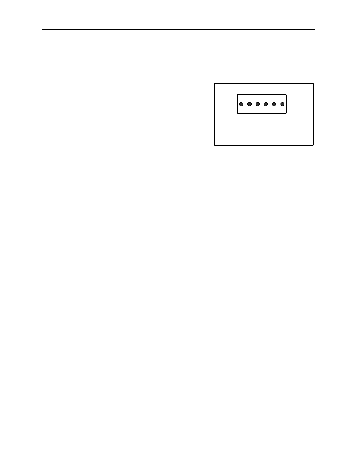
TX Audio is available from the TX+ pin on the DB25 or can be
accessed on the smaller 6-pin rear connector. The 6 Pin
connector pin out appears in Figure 3. The optional TO-23
provides balanced 600-Ohm I/O to the radio, balanced audio is
only available on the DB25 connector on the rear panel; see
Figure 1 for pin out.
1) Ground 2) PTT-NO
3) PTT-COM 4) Radio RX+
6 Pin Rear Connector Pinout
2.3.2 RX Audio Connection
The TRA223 is shipped from the factory with a single ended high impedance connection for RX Audio
from the radio. If a high-impedance point in the receiver is used, shielded cable is recommended. To
connect a receive audio from a speaker output to the TRA223 set the front panel Dip -switch SW1 position
5 to “ON”.
Note: That when the speaker output is used, the radio volume control will affect the audio levels of the
TRA223.
Single ended RX audio can be connected at pin 24 of the rear DB25 or pin 4 of the rear 6-pin connector
can be used. The audio source must be after the squelch circuit, to prevent sending continuous noise to
the remote console. The optional TO-23 provides balanced 600 -Ohm I/O to the radio, balanced audio is
only available on the DB25 connector on the rear panel; see Figure 1 for pin out.
Figure 3
2.3.3 TO- 23 Balanced Transformer option
To connect the TRA223 to a radio that requires balanced audio connections the main PCB has been
designed for the option TO-23. To install the TO-23 option remove main PCB from case and solder
transformer P/N 3180246 into T3 and P/N 3180259 into T4, remove R98, R99, R100 and R101.
Note: For 600 ohm RX input impedance; replace R77 with a 680 -ohm resistor.
2.3.4 PTT Connection
Connect the radio PTT circuit to the PTT relay contact terminals of the panel. This can be done on either
the rear DB25 or the 6 pin connectors. Usually the common of the relay contact switch is grounded and
the normally open contact connects to the PTT input. It is also possible to ground the common of the
relay internal to the unit by setting SW1 position 7 to “ON”.
2.3.5 Monitor Connection
Connect the radio MON circuit to the MON relay contact terminals of the panel. This can only be done on
the rear DB25 connector. Usually the common of each relay contact switch is grounded and the normally
open contact connects to the MON input. It is also possible to ground the common of the relay internal to
the unit by setting SW1 position 8 to “ON”.
2.3.6 RX Squelch
The TRA223 has a RX squelch feature that allows gating of the receiver audio to the remote consoles
when the COR input is pulled. The COR input is active High or Low, R103 installed is active LOW, R104
installed is active HIGH. Front panel Dip -switch SW1 position 4 controls the Squelch feature.
Page 7

Tone Remote 5
3 Level Settings and Adjustments
Once the unit is connected into the system, as it will be in general usage, the level potentiometers can be
set.
GROUND
2-W (4-TX)
4-W (RX)
RADIO RX+
RADIO TX+
2-W (4-TX)
4-W (RX)
RADIO RX-
RADIO TX-
TX DETECT
PTT MON
SW1
1 8
ON
LINE IN
RX OUT
TX OUT
MON TIME
TRA-223
3.1 Line Receive Level
It is a critical level as all of the tone decoding is based on this level. Connect an oscilloscope, RMS
voltmeter, or dbm meter to the front Ground and Line RX audio test points on the front of the TRA223.
Disable transmitter PTT circuit; adjust R92 (Line input) to Full clockwise, generate a continuous PTT
command (no voice) with a external generator or a console. The panel should respond by energizing the
PTT relay and lighting the PTT LED. Adjust R92 for –10dbm at Line RX test jack (TP3) reference to
Ground (TP2).
3.2 Radio TX Level
Due to the large range of input requirements for the radios that can be connected to the TRA223, there is
not a prescribed way of setting the Radio TX levels. Test points on the front panel of the TRA223 provide
a location to measure the actual value being placed into the radio TX inputs. The Radio TX gain
potentiometer R93 can be used to adjust these levels. Note that if the unit is placed into single ended
mode that Radio TX+ should be measured with respect to ground. The user also has the option of
placing SW1-6 into the “ON” position to decrease the output of the TX line by a factor of 10. The final
adjustment should allow for undistorted audio to be transmitted for the full range of transmission levels at
the desired deviation.
3.3 Line TX Level
The Line TX level is adjusted using R94 with the unit connected to the 600 Ohm line, connect an
oscilloscope, RMS voltmeter with an output in dbm to the Line TX test points on the front of the TRA223
and adjust for 0dbm on the line.
3.4 Monitor Adjustments
Momentarily jumper E4 to E9 (ground), the monitor relay and LED should light for a timed period. Adjust
R46 Monitor Timer for the desired monitor period, repeat as required. The Monitor relay can be
configured to operate in one of three modes:
1. Timed mode (as shipped), provides the monitor function for a timed period (adjustable for up to 9
seconds) or until a PTT command is decoded
2. Latch mode, latches upon a monitor command until reset by PTT command.
3. Refreshable Timed mode provides the monitor function for a timed period upon any tone -burst
command. Any command received during the timed period refreshes the timer for another full
timer period.
Monitor Mode SJ1 SJ2 SJ3
Timed open open open
Latched closed open open
Refreshed open closed closed
Page 8

6 Vega’s TRA223
4 Theory of Operation
4.1 Voice Circuits
In the “PTT ON” condition, the voice-signal audio path is from the line through J1 pins 4&5, EMI/RFI
filtering circuits, T1 and to the 2-wire flag (2-wire), or through J1 pins 3&6, EMI/RFI filtering circuits, T2
and to the 4-wire flag (4-wire). 2 or 4-wire selection occurs via the front panel Dip-Switch SW1 and is
routed to U14A as the 2/4 flag, U14A feeds U11D, R70, U15A, R93, U15B, U10B, C30, R79 and to TX-HI
at both 6-pin and DB26 radio connectors. The PTT tone frequency (2175Hz) and audio from U11D is
passed through U14B,C,D bandpass filter and is applied to U15A 180 out of phase, and at equal
amplitude to the signal path through R70. This results in a deep notch at 2175Hz and effectively
eliminates the PTT tone signal.
In the receive condition, the receiver audio path is from either the 6-pin and DB26 radio connectors
through R86, R94 line output control, U15C, U17, U11C, R70, U15A, U11A, U13, T1, EMI/RFI Filter and
to J1 pins 4&5 of the Line Connector. In the Full-duplex mode (SW1 position 3 “ON”), the path is from
U15C through U17, U11B to U13.
4.2 2175Hz Decoder Circuits
The tone sequence generated at the remote-control console upon PTT switch operation typically is
2174Hz at +10dbm for 130ms (guard tone), followed by a function-tone frequency at 0dbm for 40ms,
followed by 2175Hz at –20dbm (PTT holding tone) for the duration of PTT-switch operation.
Guard-tone and PTT-tone signal path is from the line through J1 pins 4&5, EMI/RFI filtering circuits, T1
and to the 2-wire flag (2-wire), or through J1 pins 3&6, EMI/RFI filtering circuits, T2 and to the 4-wire flag
(4-wire). 2 or 4 wire selection occurs via the front panel Dip -Switch SW1 and is routed to U14A as the 2/4
flag, input level control R92, pre -filter stage U5D, first bandpass filter U5C,A,B and second bandpass filter
U4C,B,A to the 2175Hz detector U1B.
4.3 Logic Circuits
CMOS logic is used in these circuits, when the tern “low” is used the DC voltage is near ground potential.
When the term “high” is used, the voltage is near +10Vdc.
When the first 2175Hz tone (guard tone) is detected, TP1 goes low; the high to low transition at TP1
triggers the 240ms timer at U2A -5, causing U2A -6 and U10A -13 to go high. This enables the audio path
from the 2/4 flag, U14A and U4D to be routed through U10A and passed to the monitor detector circuits
U3A,B,C,D and U18A. The low generated by detection of the 2050Hz monitor burst at U18A is passed to
U9F and U2B -12 the monitor relay control timer. The low to high transition at U8A-5 from U9F triggers a
50ms timer and a 62ms timer at U8B -12, U8B-9 goes low and if TP1 has gone low again due to the
presence of the PTT tone the PTT relay K2 is energized from U6B through U9C. The high at U6B-4
during PTT decode disables the receive analog gates and enables the transmit analog gates through U7B
and U7A. The U8B-9 and TP1 lows also hold U8B-14 low through U6C and U12A; this U8B -14 low
disables timeout of the 62ms timer by holding capacitor C18 in a discharged condition.
When TP1 goes high from absence of PTT tone (the console operator has released the PTT switch), the
timing capacitor C18 charges to the timeout voltage in 62ms the PTT relay is de-energized and audio
analog gates reset. When the 62ms timer has timed out a new PTT command is required to reenergize
the PTT relay; however, if a PTT tone returns before timeout of the 62ms timer, the PTT relay
reenergizes. This minimizes PTT losses from high level noise transients or from microwave flutter.
Page 9

Tone Remote 7
4.4 Monitor Function Circuits
When a monitor-function command is sent, the guard-tone detector at TP1 triggers the 240ms timer U2A,
which enables audio -signal passage through analog gate U10A. U4D and U3A are both high gain stages
and therefore the function tone signal at U3A is a rail -to-rail square wave. The square wave function tone
signal from U3A -1 is applied to the monitor bandpass filter U3B,C,D through R32. Monitor -bandpass-filter
output is rectified by CR3 and after filtering is applied to comparator op-amp U18A-3. U18A -1 goes high
triggering the 50ms timer at U8A-5 through U9F, upon 50ms timer timeout the 62ms timer is triggered, but
since TP1 is high due to the absence of PTT tone the PTT relay is not energized.
The low -to-high transition at U18A-1 triggers the monitor timer U2B through R31; U2B-10 goes high and
energizes the monitor relay K1 through U9A for a timed period. If a PTT command is decoded before
timeout of the monitor timer, the high at U6B -4 resets the monitor timer at U2B-13 through R47 and U6D
In the latched mode of operation, SJ1 is closed and when U2B is triggered, U2B -7 goes low, effectively
short-circuiting the C16 charging path through R30, R28 and R46. Upon a PTT command, U6B -4 goes
high and resets the monitor latch at U2B through R47 and U6D, U2B-10 goes low and monitor relay K1 is
de-energized.
In the refresh-monitor-timed mode of operation with SJ1 open and SJ2 and SJ3 closed, upon the decode
of any valid command, TP7 goes high, triggering the monitor timer at U2B-12 through SJ3. A PTT
command will not reset the timer in this mode, because the reset path is short -circuited by SJ2.
4.5 RX Squelch Function Circuits
The TRA223 offers the ability to gate radio RX audio by using COR or other control logic; pin -10 of J2 the
DB25 connector is the input for this feature, control logic can be either logic Hi or Low. The RX audio is
gated by U17 with control coming from J2-10 through CR13, R103 (R104 removed) and SW1-4 for logic
low, control for logic high signals come through CR13, Q1, R104 (R103 removed) and SW1-4.
Page 10

V
A
A
A
This drawing, written description or specification Is
SBC
Digitally signed
by SBC
DN: cn=SBC,
c=US
Date:
2002.09.05
10:14:06 -06'00'
Signature
Not Verified
PBH
Digitally
signed by PBH
DN: cn=PBH,
o=Telex, c=US
Date:
2002.09.05
10:39:01
-06'00'
Signature
Not Verified
PBH
Digitally
signed by PBH
DN: cn=PBH,
o=Telex, c=US
Date:
2002.09.05
10:39:01
-06'00'
Signature
Not Verified
a proprietary product of TELEX, Lincoln, NE, and
shall not be released, disclosed, nor duplicated
without the written permission of TELEX.
APPROVALS: DR BY: SBC
DATE: 06/26/2002
Telex Communications INC.
Lincoln, Nebraska USA
PROD:CHKD BY: APPD BY:
PART NO:
REV LEVEL:
879611
B
TITLE:
PCB ASSY, TRA-223
REVISIONS
RE
1 PROTOTYPE
2 ITEM 70 TO QTY 1 - REMOVED T4
ITEM 71 TO QTY 1 - REMOVED T3
DDED ITEM 86 - 50K POT - PART # 1300779
ITEM 48 CHANGED QTY FROM 4 TO 3
ITEM 84 IS SCHEMATIC 770778
B ITEM 86 CHANGED PART NUMBER TO 1300780
DESCRIPTION ECO NO DATE
PPD
6/26/02
08/08/02
08-93-02 08/28/02
09-11-02 09/05/02
LN,BE PAGE 1 OF 4
Page 11

9
4
7
3
5
5
This drawing, written description or specification Is
SBC
Digitally signed
by SBC
DN: cn=SBC,
c=US
Date:
2002.09.05
10:14:06 -06'00'
Signature
Not Verified
PBH
Digitally
signed by PBH
DN: cn=PBH,
o=Telex, c=US
Date:
2002.09.05
10:39:01
-06'00'
Signature
Not Verified
a proprietary product of TELEX, Lincoln, NE, and
shall not be released, disclosed, nor duplicated
without the written permission of TELEX.
APPROVALS: DR BY: SBC
DATE: 06/26/2002
Telex Communications INC.
Lincoln, Nebraska USA
PROD:CHKD BY: APPD BY:
PART NO:
REV LEVEL:
879611
B
TITLE:
PCB ASSY, TRA-223
TYPE DESCRIPTION PART NO. DESIGNATOR
ITEM
QTY
NEW
1 6 CAP 1UF 16V TANT A 72343719
2 1 CAP 22UF 16V ELEC. SMT 102884313
3 1 CAP 100PF 0805 72341125
4 2 CAP 0.0047UF 0805 102881146
5 24 CAP 0.1UF 0805 102881186
6 1 CAP 0.047UF 0805 102881185
7 6 CAP 0.001UF 0805 102881138
8 2 CAP 100UF 16V ELECT. SMT 102884416
9 1 CAP 220UF 25V ELEC. SMT 102884417
10 4 CAP 10UF 16V TANT B 102877065
11 4 CAP 0.01UF 0805 102881150
12 4 CAP 120PF 0805 72341126
13 2 CAP 1UF 0805 102881875
14 1 CAP 6.8PF 0805 72341111
15 8 CAP 2200PF 0805 72341141
16 12 DIODE MMBD914 SOT-23 58711000
17 2 DIODE 4004 1A DIODE SMT 16016481SMT
18 1 YEL RT ANG. LED YEL 1610631
19 1 LED RED RT ANGEL 1610630
20 4 FUSE F1250T 710109
21 4 THYRISTOR TVB170SA 710106
22 1 FUSE SMT FUSE WITH HOLDER 710105
23 8 FERRITE FERRITE 0805 723511
24 1 CONN RJ-45 8 PIN RECPT. 2862013
25 1 CONN RT ANGLE DB25-TH 640136
26 1 CONN DC PWR JACK 2.5MM 59697000
27 1 CONN 6 PIN RT ANGLE 2862056
28 1 RELAY SPDT 12V SMT 730142
29 4 INDUCTOR, 820UH 1812 723510
30 1 TRANSISTOR MMBT3904 SOT-23 54671200
31 3 RES 100K 0805 102515400
32 1 RES 10.5K 0805 102515302
33 4 RES VAR 10K LOG VADJ 1300639
34 14 RES 10K 0805 102515300
35 1 RES 681K 0805 102515480
36 1 RES 332K 0805 102515450
37 1 RES 249K 0805 102515438
38 1 RES 8.66K 0805 102515290
39 1 RES 475 OHMS 0805 102515165
40 12 RES 22.1K 0805 102515333
41 1 RES 332 OHMS 0805 102515150
42 15 RES 32.4K 0805 102515349
C1 C2 C3 C5 C17 C18 C24 C36 C
C16
C19
C20 C21
C22 C12 C29 C11 C38 C48 C49 C50 C51 C52 C53
C54 C55 C56 C57 C58 C59 C60 C61 C62 C39 C43
C88 C92
C25
C27 C28 C41 C45 C90 C9
C32 C33
C35
C4 C26 C34 C3
C40 C44 C89 C9
C42 C46 C91 C9
C47 C30
C6
C7 C8 C10 C13 C14 C15 C23 C31
CR1 CR2 CR3 CR4 CR5 CR6 CR7 CR8 CR9 CR10
CR12 CR13
D1 D2
DS1
DS2
F1 F2 F3 F4
F5 F6 F7 F11
F8
FB1 FB2 FB3 FB4 FB5 FB6 FB15 FB16
J1
J2
J3
J4
K1 K2
L1 L2 L5 L6
Q1
R1 R3 R8
R10
R11 R20 R24 R81
R12 R58 R59 R61 R63 R82 R7 R88 R90 R91 R96
R102 R105 R106
R14
R22
R25
R26
R27
R28 R30 R31 R47 R48 R51 R52 R54 R57 R60 R15
R97
R33
R34 R43 R13 R37 R38 R41 R64 R68 R70 R71 R72
R73 R17 R19 R23
LN,BE Page 2 of 4
Page 12

This drawing, written description or specification Is
8
4
9
4
5
A/R
SBC
Digitally signed
by SBC
DN: cn=SBC,
c=US
Date:
2002.09.05
10:14:06 -06'00'
Signature
Not Verified
PBH
Digitally
signed by PBH
DN: cn=PBH,
o=Telex, c=US
Date:
2002.09.05
10:39:01
-06'00'
Signature
Not Verified
a proprietary product of TELEX, Lincoln, NE, and
shall not be released, disclosed, nor duplicated
without the written permission of TELEX.
APPROVALS: DR BY: SBC
DATE: 06/26/2002
Telex Communications INC.
Lincoln, Nebraska USA
PROD:CHKD BY: APPD BY:
PART NO:
REV LEVEL:
879611
B
TITLE:
PCB ASSY, TRA-223
TYPE DESCRIPTION PART NO. DESIGNATOR
ITEM
43 1 RES 274 OHMS 0805 102515142
44 1 RES 15.0K 0805 102515317
45 8 RES 20K 0805 102515329
46 1 RES 16.2K 0805 102515320
47 1 RES 976 OHMS 0805 102515195
48 3 POT 10K HORIZ. ADJ. T/H 1300778
49 1 RES 51.1K 0805 102515368
50 1 RES 3K 0805 102515246
51 1 RES 1.5K 0805 102515217
52 2 RES 4.75K 0805 102515265
53 2 RES 60.4K 0805 102515375
54 2 RES 27.4K 0805 102515342
55 1 RES 100 OHMS 0805 102515100
56 2 RES 150 OHMS 0805 102515117
57 1 RES 953 OHMS 0805 102515194
58 1 RES 28.7K 0805 102515344
59 5 RES 1K 0805 102515200
60 3 RES 61.9K 0805 102515376
61 1 RES 10 OHMS 2010 102405100
62 1 RES 15 OHMS 0805 102515017
63 1 RES 31.6K 0805 102515348
64 1 POT 10K 15 TURN VADJ 1300673
65 1 RES 68 OHMS 2 WATT LEADED 1311853
66 1 RES 200K 0805 102515429
67 1 RES 680 OHMS 0805 102515180
68 6 RES 0 OHMS 0805 102506000
69 1 SWITCH PIANO DIP 8 POS 57590004
70 1 XFMR 600CT:600CT 3180259
71 1 XFMR 10KCT:10KCT 3180246
QTY
NEW
R39
R4
R40 R44 R35 R36 R16 R67 R74 R1
R42
R45
R92 R93 R9
R49
R5
R50
R55 R53
R56 R32
R6 R2
R62
R65 R79
R66
R69
R75 R83 R87 R89 R21
R76 R84 R2
R77
R78
R8
R80
R86
R9
R95
R98 R99 R100 R101 R103 R10
SW1
T1
T2
TP2 TP3 TP9 TP10 TP14 TP15 TP16 TP17 TP18
72 10 TEST POINT TP/PROBE 2861965
73 2 IC LM358AM 53227104
74 2 IC 4066B SO14 53266108
75 1 IC NE5532 DUAL OP AMP 760268
76 1 IC UA7810CKTER 760275
77 1 IC DG417DY SO8 760332
78 2 IC CD4538BCM SO16 53266112
79 5 IC TL084CD QUAD OP AMP 4300047
80 1 IC CD4001BD 53266115
81 1 IC CD4025BM 4300106
82 2 IC ULN2004AD SO16 16030008SMS
TP19
U1 U18
U10 U11
U13
U16
U17
U2 U8
U3 U4 U5 U14 U1
U6
U7
U9 U12
83 1 PCB PRINTED CIRCUIT BOARD 750623
84 0 REFERENCE SCHEMATIC 770778
85
PASTE SOLDERPASTE BE738
86 1 POT 500K LOG 1300780 R46
LN,BE Page 3 of 4
Page 13

SBC
Digitally signed
by SBC
DN: cn=SBC,
c=US
Date:
2002.09.05
10:14:06 -06'00'
Signature
Not Verified
PBH
Digitally
signed by PBH
DN: cn=PBH,
o=Telex, c=US
Date:
2002.09.05
10:39:01
-06'00'
Signature
Not Verified
Page 14

PBH
Digitally signed by PBH
DN: cn=PBH, o=Telex,
c=US
Date: 2002.07.03
07:50:25 -06'00'
Signature Not Verified
PBH
Digitally signed by PBH
DN: cn=PBH, o=Telex,
c=US
Date: 2002.07.03
07:50:25 -06'00'
Signature Not Verified
CLS
Digitally signed by CLS
DN: cn=CLS
Date: 2002.07.08
08:45:42 -05'00'
Signature Not Verified
PBH
Digitally signed by PBH
DN: cn=PBH, o=Telex,
c=US
Date: 2002.07.03
07:50:25 -06'00'
Signature Not Verified
Page 15

Tone Remote 15
nel
Connector
1 2 3 4 5 6
5) Radio TX+
6) Power
6 Pin out and Jumper Settings Quick Reference Table
6.1 Adjustments
Line Input Level (R92)
Line Output Level (R93)
Radio TX Modulation (R93)
Monitor Timer (R46)
6.2 SW1 Dip- switch Positions
1. 2-Wire “ON” / 4-Wire “OFF”
2. 4-Wire “ON” / 2-Wire “OFF”
3. Full-Duplex
4. Squelch
5. Radio RX Level “ON” = Speaker / “OFF” = High -Impendence
6. Radio TX Level “ON” = Low level / “OFF” = High level
7. Ground on PTT relay common
8. Ground on Monitor relay common
6.3 Radio Connections
DB25 Rear Pa
1) Ground 2) PTT-NO
3) PTT-COM 4) Radio RX+
6 Pin Rear Connector Pinout
6.4 Line Connections
1 2 3 4 5 6 7 8
1)
2)
3) RX +
4) TX +/ (RX + 2W)
5) TX -/ (RX - 2W)
6) RX -
7)
8)
Connector View
1-PTT NC 20-+POWER
14-PTT NO 82-PTT COM 2115-MON NC 93-MON NO 2216-MON COM 10-SQUELCH
4- 2317- 115- 24-RX+
18- 12-RX6- 25-TX+
19- 13-TX 7-GROUND
Page 16

16 Vega’s TRA223
6.5 DB25 Cable Color codes
PIN ON RADI O
DB25 Pin Signal Color
1 = PTT N.C. Brown
2 = PTT COM Red
3 = MON N.O. Orange
4 = Pink
5 = Yellow
6 = Green
7 = GROUND Lt. Green
8 = Blue
9 = Violet
10 = Gray
11 = White
12 = RX- Black
13 = TX- Brown/WHT
14 = PTT N.O. Red/WHT
15 = MON N.C. Red/BLK
16 = MON.COM Orange/WHT
17 = Orange/BLK
18 = Pink/BLK
19 = Yellow/BLK
20 = +V Green/WHT
21 = Green/BLK
22 = Blue/WHT
23 = Violet/WHT
24 = RX+ Gray/BLK
25 = TX+ Black/WHT
Shell = Shield
CONNECTOR
Page 17

Tone Remote 17
7 Warranty, Service, Repair, and Comments
Important! Be sure the exact return address and a description of the problem or
work to be done are enclosed with your equipment .
Warranty (Limited)
All Telex Communications, Vega signaling products are guaranteed against malfunction due to
defects in materials and workmanship for three years, beginning at the date of original purchase.
If such a malfunction occurs, the product will be repaired or replaced (at our option) without
charge during the three-year period, if delivered to the Telex factory. Warranty does not extend to
damage due to improper repairs, finish or appearance items, or malfunction due to abuse or
operation under other than the specified conditions, nor does it extend to incidental or
consequential damages. Some states do not allow the exclusion or limitation of incidental or
consequential damages, so the above limitation may not apply to you. This warranty gives the
customer specific legal rights, and there may be other rights which vary from state to state.
Factory Service Center
TELEX Communications, Inc.
Vega Signaling Products
8601 East Cornhusker Highway, Lincoln, Nebraska, 68507
Phone: (402) 465-7026 / (800) 752 -7560 Fax: (402) 467 -3279
E-mail: vega@telex.com, Web: www.vega-signaling.com
Claims
No liability will be accepted for damages directly or indirectly arising from the use of our materials or from
any other causes. Our liability shall be expressly limited to replacement or repair of defective materials.
Suggestions or Comments
We’d appreciate your input. Please send us your suggestions or comments concerning this manual, by
fax (402 -467-3279) or e-mail them to: vega@telex.com
Visit our web site at www.vega-signaling.com
Page 18

18 Vega’s TRA223
8 TRA223 Specifications
Operating Temperature Range: 0 to 55°C for full
specifications
Power Requirements: +12 to +16 Vdc, semi-
regulated, 500ma.
Relay Contact Ratings: 1A at 125Vac
Radio Interface: ±45 Vdc withstand rating
Line to TX Output Gain: -26dB to +16dB into mic
input load or –10 to +22db into 600Ω load
Radio Output Level: -60 to –18 dbm for
microphone level or -40 to +2dBm into 600Ω
load, adjustable
Radio Output Impedance: 22Ω TX ON, typical;
22KΩ TX OFF, typical, 600Ω for balanced
mode (TO -23 option)
Radio Input Level: 100mVrms to 16Vrms,
adjustable
Audio Distortion: 2% THD maximum
Frequency Response: ±1.5 dB, 300 to 3000 Hz,
except at 2175 Hz notch frequency
Line Output Level: -30 to +12dBm, adjustable
Line Input/Output Impedance: 600Ω nominal
Sensitivity: Ultimate sensitivity, -60dBm PTT tone
MON timer: 1 to 10 seconds, adjustable
PTT Tone Detect Bandwidth: ± 50 Hz around
2175Hz, with sensitivity set 12dB above
threshold of detection
Notch Frequency Rejection: 45 dB minimum
Notch Frequency Bandwidth: 70 Hz at -3dB
points. ±1Hz at –40dB.
Dimensions: 7” Wide, 7” Deep, by 1.5” High
TELEX Communications, Inc.
Vega Signaling Products
8601 East Cornhusker Highway, Lincoln, Nebraska, 68507
Phone: (402) 465-7026 / (800) 752 -7560 Fax: (402) 467 -3279
E-mail: vega@telex.com, Web: www.vega-signaling.com
 Loading...