

Page 1
Operating Instruction
in
out
VEGATOR 631 Ex
Signal conditioning
instrument
s
conditioning
and communication
Signal
instruments
Page 2

Contents
Contents
1 About this
1.1 Function. . . . . . . . . . . . . . . . . . . . . . . . . . . . . . . . . .
1.2 Target group . . . . . . . . . . . . . . . . . . . . . . . . . . . . . .
1.3 Symbolism used. . . . . . . . . . . . . . . . . . . . . . . . . . . .
2 For your safety
2.1 Authorised personnel . . . . . . . . . . . . . . . . . . . . . . . .
2.2 Appropriate use . . . . . . . . . . . . . . . . . . . . . . . . . . . .
2.3 Warning about misuse . . . . . . . . . . . . . . . . . . . . . . .
2.4 General safety instructions . . . . . . . . . . . . . . . . . . . .
2.5 CE conformity . . . . . . . . . . . . . . . . . . . . . . . . . . . . .
2.6 Safety instructions for Ex areas . . . . . . . . . . . . . . . . .
2.7 Environmental instructions. . . . . . . . . . . . . . . . . . . . .
3 Product description
3.1 Configuration . . . . . . . . . . . . . . . . . . . . . . . . . . . . . .
3.2 Principle of operation . . . . . . . . . . . . . . . . . . . . . . . .
3.3 Operation. . . . . . . . . . . . . . . . . . . . . . . . . . . . . . . . .
3.4 Packaging, transport and storage . . . . . . . . . . . . . . .
4 Mounting
4.1 General instructions . . . . . . . . . . . . . . . . . . . . . . . . .
4.2 Mounting instructions . . . . . . . . . . . . . . . . . . . . . . . .
5 Connecting to power supply
5.1 Preparing the connection . . . . . . . . . . . . . . . . . . . . .
5.2 Connection procedure. . . . . . . . . . . . . . . . . . . . . . . .
5.3 Wiring plan. . . . . . . . . . . . . . . . . . . . . . . . . . . . . . . .
6 Set up
6.1 Adjustment system . . . . . . . . . . . . . . . . . . . . . . . . . .
6.2 Adjustment elements . . . . . . . . . . . . . . . . . . . . . . . .
6.3 Switching point adjustment . . . . . . . . . . . . . . . . . . . .
document
4
4
4
5
5
5
5
6
6
6
7
8
8
8
10
10
13
13
14
18
19
23
7 Maintenance and fault rectification
7.1 Maintenance . . . . . . . . . . . . . . . . . . . . . . . . . . . . . .
7.2 Remove interferences. . . . . . . . . . . . . . . . . . . . . . . .
7.3 Instrument repair . . . . . . . . . . . . . . . . . . . . . . . . . . .
8 Dismounting
8.1 Dismounting steps . . . . . . . . . . . . . . . . . . . . . . . . . .
8.2 Disposal . . . . . . . . . . . . . . . . . . . . . . . . . . . . . . . . .
9 Supplement
9.1 Technical data . . . . . . . . . . . . . . . . . . . . . . . . . . . . .
2 VEGATOR 63
26
26
27
28
28
23440-EN-090130
29
1 Ex • Signal conditioning instrument
Page 3

Contents
23440-EN-090130
VEGATOR 631 Ex • Signal conditi
Supplementary documentation
Information:
Suppleme
with the delivery. You can find them listed in chapter "Product
description".
ntary documents appropriate to the ordered version come
oning instrument 3
Page 4
1 About this document
1 About this document
1.1 Function
is operating instructions manual provides all the information you
Th
need for mounting, connection and setup as well as important
instructions for maintenance and fault rectification. Please read this
information before putting the instrument into operation and keep this
manual accessible in the immediate vicinity of the device.
1.2 Target group
This operating instructions manual is directed to trained qualified
personnel. The contents of this manual should be made available to
these personnel and put into practice by them.
1.3 Symbolism used
Information, tip, note
This
symbol indicates helpful additional information.
Caution: If this
result.
Warning: If this warning is ignored, injury to persons and/or serious
damage to the instrument can result.
Danger: If this warning is ignored, serious injury to persons and/or
destruction of the instrument can result.
applications
Ex
Th
symbol indicates special instructions for Ex applications.
is
l List
The dot set in front indicates a list with no implied sequence.
warning is ignored, faults or malfunctions can
à Action
This a
rrow indicates a single action.
1 Sequence
Numbers set in front indicate successive steps in a procedure.
23440-EN-090130
4 VEGATOR 63
1 Ex • Signal conditioning instrument
Page 5

2 For your safety
2 For your safety
2.1 Auth
All operations described in this operating instructions manual must be
carried out only by trained specialist personnel authorised by the plant
operator.
During work on and with the device the required personal protective
equipment must always be worn.
orised personnel
2.2 Appropriate use
VEGATOR 631 Ex is a universal signal conditioning instrument for
connection of a level switch.
You can find detailed information on the application range in chapter
"Product description".
Operational reliability is ensured only if the instrument is properly used
according to the specifications in the operating instructions manual as
well as possible supplementary instructions.
For safety and warranty reasons, any invasive work on the device
beyond that described in the operating instructions manual may be
carried out only by personnel authorised by the manufacturer. Arbitrary
conversions or modifications are explicitly forbidden.
2.3 Warning about misuse
Inappropriate or incorrect use of the instrument can give rise to
application-specific hazards, e.g. vessel overfill or damage to system
components through incorrect mounting or adjustment.
23440-EN-090130
VEGATOR 631 Ex • Signal conditi
2.4 General safety instructions
This is a high-tech instrument requiring the strict observance of
standard regulations and guidelines. The user must take note of the
safety instructions in this operating instructions manual, the countryspecific installation standards as well as all prevailing safety
regulations and accident prevention rules.
The instrument must only be operated in a technically flawless and
reliable condition. The operator is responsible for trouble-free
operation of the instrument.
During the entire duration of use, the user is obliged to determine the
compliance of the required occupational safety measures with the
current valid rules and regulations and also take note of new
regulations.
oning instrument 5
Page 6

2 For your safety
2.5 CE conformi
This device fulfills the legal requirements of the applicable EC
guidelines. By attaching the CE mark, VEGA provides a confirmation
of successful testing. You can find the CE conformity declaration in the
download area of
ty
www.vega.com.
2.6 Safety instructions for Ex areas
Please note the Ex-specific safety information for installation and
operation in Ex areas. These safety instructions are part of the
operating instructions manual and come with the Ex-approved
instruments.
2.7 Environmental instructions
Protection of the environment is one of our most important duties. That
is why we have introduced an environment management system with
the goal of continuously improving company environmental protection.
The environment management system is certified according to DIN
EN ISO 14001.
Please help us fulfil this obligation by observing the environmental
instructions in this manual:
l Chapter "Packaging, transport and storage"
l Chapter "Disposal"
6 VEGATOR 63
23440-EN-090130
1 Ex • Signal conditioning instrument
Page 7
3 Product description
3
1
2
1 2 3 4
5 6 7 8
9 10 11 12 13 14
631Ex
on
0 10
5
!
3 Product description
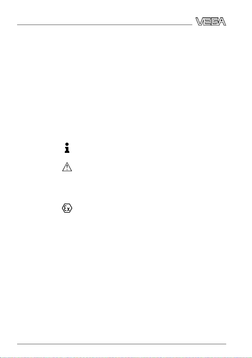
Scope of delivery
Components
3.1 Configurat
ion
The scope of delivery encompasses:
l VEGATOR 631 Ex signal conditioning instrument
l Transparent cover (lead-sealable)
l Terminal socket
l Bridges (4 pieces)
l Coded pins (2 pieces)
l Ex label
l Ex separating chamber
l Documentation
- this operating instructions manual
- Ex-specific "Safety instructions" (with Ex-versions)
- if necessary, further certificates
VEGATOR 631 Ex consists of:
l VEGATOR 631 Ex signal conditioning instrument
Type label
23440-EN-090130
VEGATOR 631 Ex • Signal conditi
Fig. 1: VEGATOR 631 Ex
1 Ex separating
2 Terminal socket
3 Transparent cover
The type label contains the most important data for identification and
use of the instrument:
chamber with Ex version
l Article number
l Serial number
l Technical data
l Article numbers documentation
oning instrument 7
Page 8

3 Product description
Application area
Functional principle
Power supply
The serial number allows you to access the delivery data of the
instrument
search".
via
www.vega.com, "VEGA Tools" and "serial number
3.2 Principle of operation
VEGATOR 631 Ex is a single signal conditioning instrument for
processing the signals of conductive probes.
The VEGATOR 631 Ex signal conditioning instrument powers
connected sensors and simultaneously processes their measuring
signals.
When the medium reaches the switching point of the sensor, the
voltage between sensor and VEGATOR 631 Ex drops. The output
relays then switch according to the set mode.
Detailed information about the power supply can be found in chapter
"Technical data".
3.3 Operation
The integration time and the mode (A/B) can be preset via a DIL switch
block on the signal conditioning instrument.
A potentiometer for adjustment the switching point is located on the
front panel of VEGATOR 631 Ex.
3.4 Packaging, transport and storage
Packaging
Transport
Transport inspection
Storage
8 VEGATOR 63
Your instrument was protected by packaging during transport. Its
capacity to handle normal loads during transport is assured by a test
according to DIN EN 24180.
The packaging of standard instruments consists of environmentfriendly, recyclable cardboard. For special versions, PE f oam or PE foil
is also used. Dispose of the packaging material via specialised
recycling companies.
Transport must be carried out under consideration of the notes on the
transport packaging. Nonobservance of these instructions can cause
damage to the device.
The delivery must be checked for completeness and possible transit
damage immediately at receipt. Ascertained transit damage or
concealed defects must be appropriately dealt with.
Up to the time of installation, the packages must be left closed and
stored according to the orientation and storage markings on the
outside.
23440-EN-090130
1 Ex • Signal conditioning instrument
Page 9

3 Product description
Storage and transport
temperature
Unless otherwise indicated, the p
ackages must be stored only under
the following conditions:
l Not in the open
l Dry and dust free
l Not exposed to corrosive media
l Protected against solar radiation
l Avoiding mechanical shock and vibration
l Storage and transport temperature see chapter "Supplement -
Technical data - Ambient conditions"
l Relative humidity 20 … 85 %
23440-EN-090130
VEGATOR 631 Ex • Signal conditi
oning instrument 9
Page 10
4 Mounting
4 Mounting
Installation location
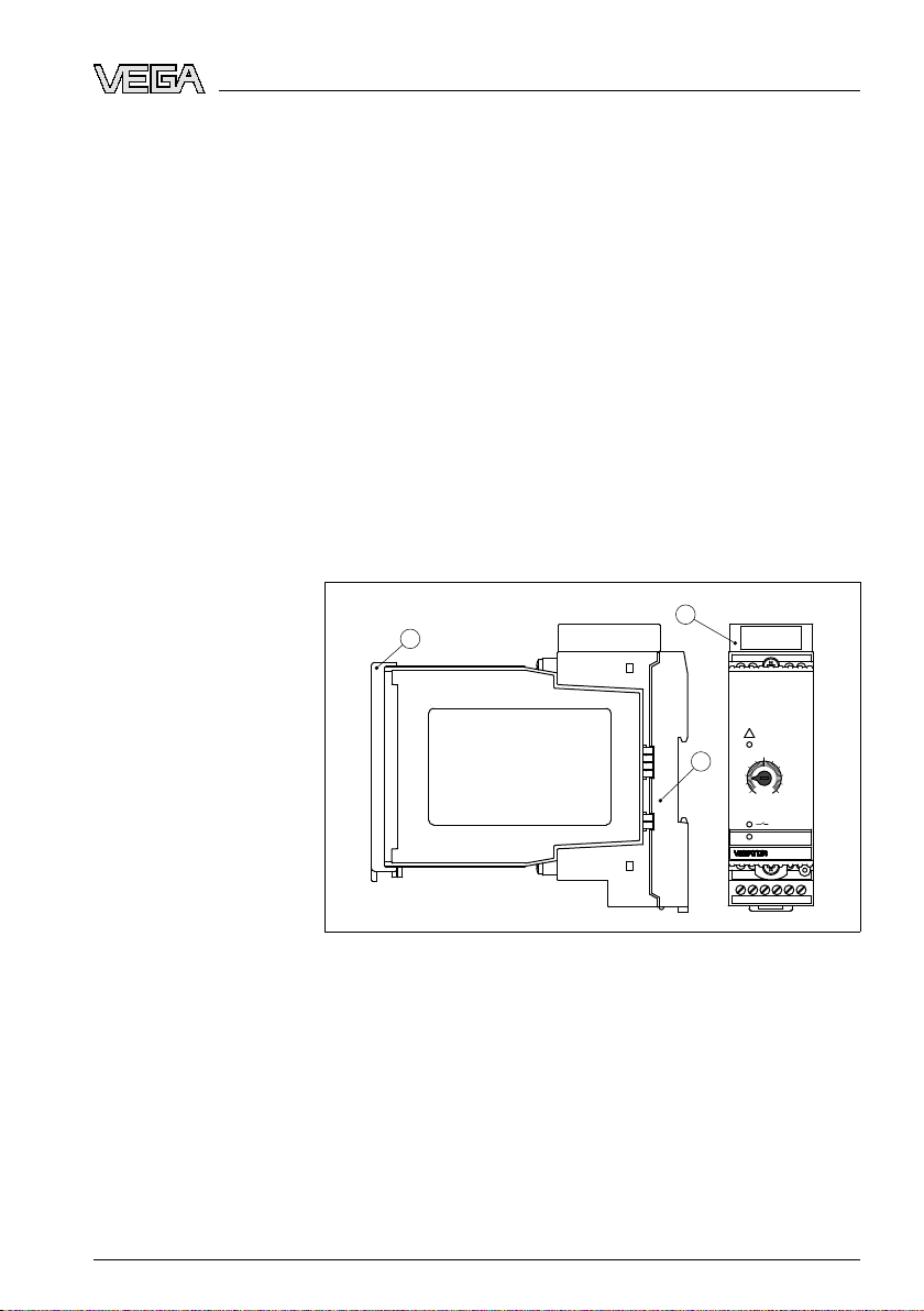
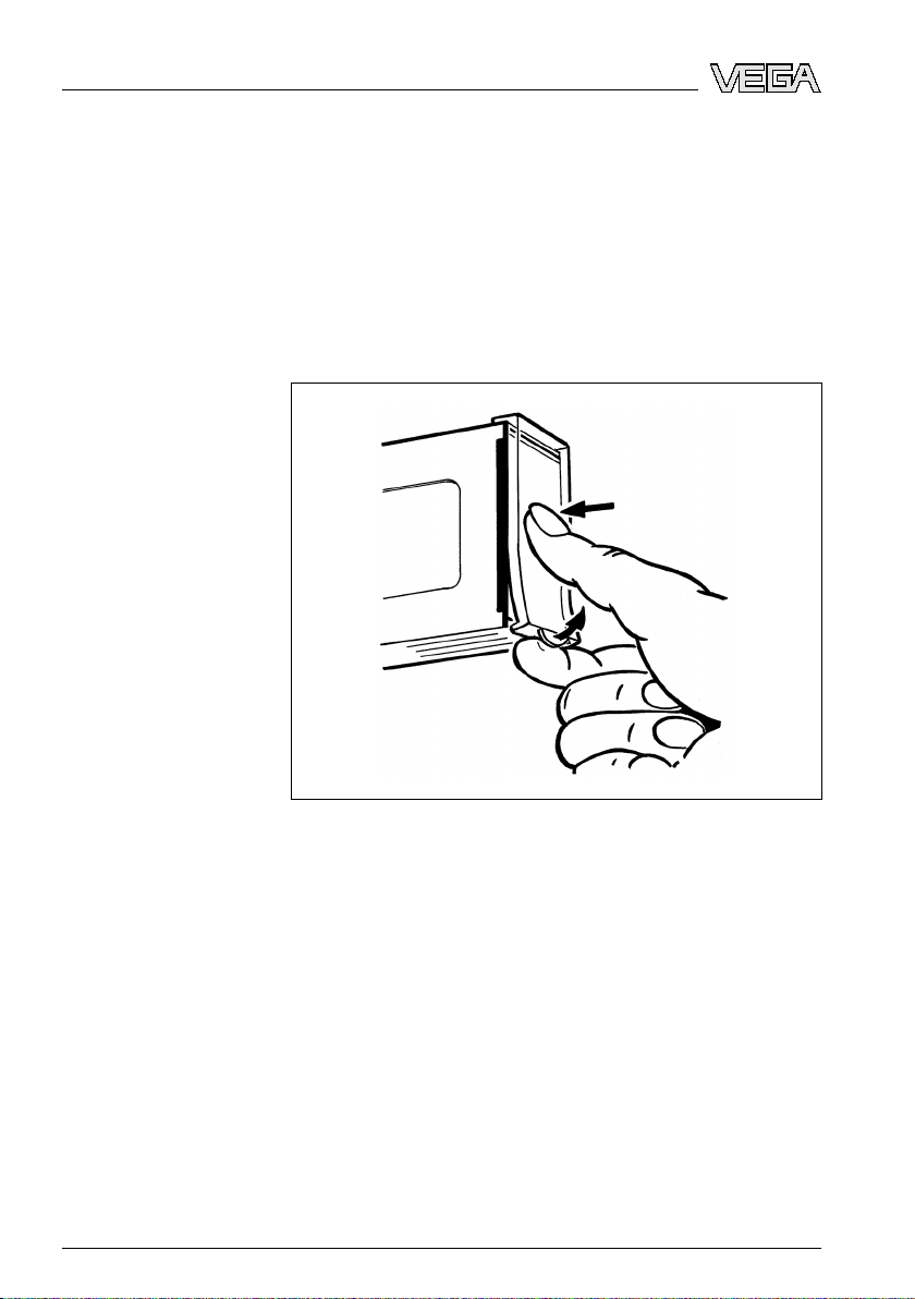
Transparent cover
4.1 General ins
VEGATOR 631 Ex signal conditioning instrument with plug-in socket
for mounting on carrier rail according to EN 50022.
The front plate of VEGATOR 631 Ex can be provided with a leadsealable transparent cover to protect the instrument against unauthorised or inadvertent adjustment. See the following figure on how to
remove the transparent cover.
tructions
cover
Housing IP 65
Fig. 2: Removing the transparent
For moisture-protected mounting outside the switching cabinet, we
offer an insulated protective housing with transparent cover (IP 65) for
surface mounting.
In this housing you can mount a maximum of 3 instruments of 36 mm
width.
4.2 Mounting instructions
Mounting
10 VEGATOR 63
The plug-in socket is constructed for carrier rail mounting according to
EN 50022. Power supply is connected to terminals 9 and 10. For
neighbouring signal conditioning instruments, it is possible to continue
connection L1 and N directly via the supplied bridges.
23440-EN-090130
1 Ex • Signal conditioning instrument
Page 11

1 2 43
4 Mounting
Danger:
bridges must never be used with single instruments or at the end
The
of a row of instruments. If this rule is not heeded, there is a danger of
coming into contact with the operating voltage or causing a short
circuit.
Ex separating chamber
A VEGATOR 631 Ex in E
x version is an auxiliary, intrinsically safe
instrument and must not be installed in explosion-endangered areas.
Before setup, the Ex separating chamber must be attached (as shown
below) with Ex versions. Safe operation can be only ensured if the
operating instructions manual and the EG type approval certificate are
observed. VEGATOR 631 Ex must not be opened.
Close the upper terminals according to the following illustration.
Fig. 3: Mounting the separating
chamber
Instrument coding
23440-EN-090130
VEGATOR 631 Ex • Signal conditi
All signal conditioning instruments are provided with different gaps
dependent on type and version (mechanical coding).
The plug-in socket is provided with coded pins that can be inserted to
prevent accidental interchanging of the various instrument types.
With a VEGATO
R 631 Ex in Ex version, the supplied coded pins (type
coded pin and Ex coded pin) must be inserted by the user according to
the below chart.
oning instrument 11
Page 12

5 6 7 8
14131211109
4321
A
B
C
1
2
3
7
8
9
N
L
1
-
+
1
4
2
3
4 Mounting
Fig. 4: Plug-in socket VEGATOR 631 Ex
1 Ex
separating chamber
2 Ex coding with Ex version (A)
3 Type coding for VEGATOR 631 Ex (3)
4 Bridges for looping the operating voltage
12 VEGATOR 63
23440-EN-090130
1 Ex • Signal conditioning instrument
Page 13

5 Connecting to power supply
5 Connecting to power supply
Note safety instructions
Take note of
safety instructions for Ex applications
Select power supply
Selecting connection
cable
Cable screening and
grounding
5.1 Preparin
Always keep in mind the following safety instructions:
l Connect only in the complete absence of line voltage
l If overvoltage surges are expected, overvoltage arresters should
be installed
Tip:
We recomm
VEGATOR 631 Ex) and B62-36G (sensor supply).
In hazardous areas you should take note of the appropriate
regulations, con
and power supply units.
The power supply can be 20 … 253 V AC, 50/60 Hz or 20 … 72 V DC.
Power supply of VEGATOR 631 Ex is connected with standard cable
according to the national installation standards.
The sensors are connected with standard two-wire cable without
screen. If electromagnetic interference is expected which is above the
test values of EN 61326 for industrial areas, screened cable should be
used.
From a cable length of 50 m use one cable for each signal conditioning
instrument.
If you are using a common cable, the min. and max. cables must be
screened. The screen must be connected the ground on both sides.
g the connection
end VEGA overvoltage arresters B61-300 (power supply
formity and type approval certificates of the sensors
Select connection cable for Ex
applications
23440-EN-090130
VEGATOR 631 Ex • Signal conditi
Take note of the corresponding installation regulations for Ex
ications.
appl
5.2 Connection procedure
Move on to electrical connection and proceed as follows:
1 Snap the socket without VEGATOR 631 Ex onto the carrier rail
2 Connect the sensor cable to terminal 1 and 3 (see the following
wiring plans)
3 Connect power supply (switched off) to terminal 9 and 10
4 Insert VEGATOR 631 Ex into the plug-in socket and screw it down
tightly
The electrical connection is finished.
oning instrument 13
Page 14

1 2
5
4
1 32 4
5 6
9 1310 1412
7 8
L
(+)
N
(–)
1
2
3
6
5 Connecting to power supply
Limit level measurement
Before setting up Ex
versions, make sure the Ex separating chamber is
plugged (above the sensor terminals). The pins for type and Ex coding
must also be inserted correctly.
5.3 Wiring plan
Fig. 5: Limit
1 Relay
2 Power supply
3 Transistor output
4 Mass
5 max.
6 Probe, e.g. EL1
level
output
measurement
14 VEGATOR 63
23440-EN-090130
1 Ex • Signal conditioning instrument
Page 15

1 3
2
5
6
4
1 32 4
5 6
9 1310 1412
7 8
L
(+)
N
(–)
1
2
3
7
1
2
3
Two-point control (min./
max. control)
Fig. 6: Two-point control
1 Relay output
2 Power
supply
3 Transistor output
4 Mass
5 Max.
6 Min.
7 Probe, e.g. EL3
5 Connecting to power supply
23440-EN-090130
VEGATOR 631 Ex • Signal conditi
Note:
Mutiplerod
probes connected to several signal conditioning instru-
ments or to a multiple channel instrument need a ground rod to keep
the signal conditioning instruments from influencing each other.
oning instrument 15
Page 16

1 32 4
5 6
9 10 131412
7 8
1
2
3
4
1 32 4
5 6
9 10 131412
7 8
L
(+)
N
(–)
L
(+)
N
(–)
1
4
2
3
5
6
7
8
A B
4
1
2
3
5 Connecting to power supply
Two-point control (min./
max.) with overfill protection
Fig. 7: Two-point control with
overfill protection
1 Relay output
2 Power supply
3 Transistor output
4 Max. overfill protection
5 Min.
6 Max.
7 Mass
8 Probe, e.g. EL3
A Overfill protection
B Min./max. control
16 VEGATOR 63
23440-EN-090130
1 Ex • Signal conditioning instrument
Page 17

+
-
+
+
+
-
-
1
2
3
R
S
R
S
U
CE
U
CE
Circuit of the transistor
outputs
5 Connecting to power supply
Fig. 8: Circuit of the
1 VEGATOR 631 Ex
2 VEGATOR 631 Ex
3 PLC
The resistor R
R
S
47 Ω 0.25 W
150 Ω 0.75 W
330 Ω 1.5 W
560 Ω 2.2 W
transistor outputs
serves as short-circuit protection.
S
P
23440-EN-090130
VEGATOR 631 Ex • Signal conditi
oning instrument 17
Page 18

Typ 600-1
on
5 6 7 8
9 10 12 13 14
5 6 7 8
141312109
4321
TEST
EEx ia
+
-
L
1
N
DISBUS
0...10V
9
8
7
3
2
1
C
B
A
12
Plug-in socket
6
5
10
7
7
8
9
1
2
3
4
6 Set up
6 Set up
6.1 Adjustm
Fig. 9: Indicating
ent system
and
adjustment
1 Control lamp - Fault signal (LED red)
2 Potentiometer for switching point adjustment
3 Control lamp - Output (LED yellow)
4 Control lamp - Power supply (LED green)
5 Bridge for adjusting the fault signal
6 Terminals for probe
7 Function coding Ex version
8 Instrument coding
9 Sockets for bridges
10 Transistor output
11 Relay output
12 Power supply
18 VEGATOR 63
elements
23440-EN-090130
1 Ex • Signal conditioning instrument
Page 19

maximum
3 4
IP 30
60mA
-
+
max: 36V
5 6
R
nsp. I
a
: -20É+60¡C
power supply
20É72VDC
1...8 VA
20É250 VAC
L
N
Sensor
1 2
Terminal
12 13
out
14
2A
125VA
max.250VAC
9 10
+
-
CE
VEGA TOR 631 EX
minimum
1 2 3 4
12
6
2
A
B
off
sec t
1
32
6 Set up
Control lamps
23440-EN-090130
VEGATOR 631 Ex • Signal conditi
Fig. 10: Indicating
and
adjustment
elements
1 DIL switch block
2 Type label
3 Transparent cover
6.2 Adjustment elements
Control lamps (LED) in the front plate indicate operation, switching
status and fault signal.
l Green
- Operating control lamp
- Mains voltage on, instrument is
l Red
- Failure lamp
- Fault on the sensor circuit due to sensor failure or line break
- The relay deenergises in case of failure
l Yellow
- Relay
control lamp
- The yellow relay control lamp reacts depending on the set
mode (A/B)
oning instrument 19
operating
Page 20

1 2 3 4
12
62A
B
off
sec t
6 Set up
Potentiometer for
switching point adjustment
DIL switch block
- Generally the relay control lamp shows the activated
gized) condition of the relay
(ener
- A dark relay control lamp means that the relay is deenergised
(transistor
A potentiometer for switching point adaptation is located on the front
plate of the signal conditioning instrument. With this potentiometer you
can adapt the measuring system to the conductivity of the product.
On top to the side (covered when mounted) there is a DIL switch block
with four switches. The individual switches are assigned as follows:
l 1 - A/B mode
- A - Max. detection or overflow protection
- B - Min. det
l 2 - Integration time 2 s
l 3 - Integration time 6 s
l 4 - Integration time 12 s
With switch 1 you can adjust the mode (A - overfill protection or B - dry
run protection).
Fig. 11: DIL switch
blocks)
ection or dr
block
y run detection
In
example (see previous illustration), mode A (max. detection or
the
overfill protection) is selected (switch 1). The integration time is set to 8
seconds (switch 2, 3 and 4).
You can adjust the integration time accordingly with switch 2, 3 and 4.
The time periods of the activated time switches add up. The set time
applies to the switch on as well as the switch off delay.
Switch 1 2 3 4
Time 2 s 6 s 12 s
0.2 s A/B off off off
2 s A/B on off off
6 s A/B off on off
8 s A/B on on off
12 s A/B off off on
14 s A/B on off on
18 s A/B off on on
20 s A/B on on on
20 VEGATOR 63
23440-EN-090130
1 Ex • Signal conditioning instrument
Page 21

2
3
1
2
3
1
1 2 3 4
1
2
3
1
2
31
1 2 3 4
1
6 Set up
Fault signal adjustment,
bridge
To implement line monitoring, you ha
ve to mount a resistor of 220 kΩ
between terminals 1 and 2 in the connection housing of the probe. This
means that with single point control, the measuring and ground
electrode are monitored and with two-point control, the max. and
ground electrode.
When a fault message is generated, the switching output is
simultaneously activated.
Fig. 12: Measuring system with line monitoring
1 Resistor (220 kΩ)
If
a fault message is not wanted, a bridge must be provided on the
signal conditioning instrument instead of the resistor in the connection
housing of the probe.
Note:
Theline
monitoring and the fault signal are inactive with this bridge.
Fig. 13: Measuring system without line monitoring
1 Bridge
between terminal 3 and 4
23440-EN-090130
VEGATOR 631 Ex • Signal conditi
If a measuring system is used as part of an overfill prote
the bridge on the signal conditioning instrument must not be closed.
With Ex probes, the resistor in the probe housing is already present.
oning instrument 21
ction system,
Page 22

1
2
3
6 Set up
Mode switch
You can find the
electrical connection of VEGATOR 631 Ex in the
operating instructions manual of the corresponding signal conditioning
instrument.
Line monitoring
With Ex versions, this 220 kΩ resistor is already integrated ex factory in
the connection housing of the probe. The Ex measuring system (max.
and ground connection cable of the probe to the signal conditioning
instrument) is generally monitored for line break.
You can set mode A or B by means of the selection switch.
Mode A
Preferrably as overflow protection, compulsory as overfill protection.
Fig. 14: Mode A - Overfill
protection
Mean
with covered max. electrode:
s
l Relay deenergises, connection 12 - 13 is connected through relay
l Transistor output blocks
l Control lamp - Output extinguishes
Means with uncovered max. electrode (level detection) or min.
electrode (two-point control):
l Relay energises, connection 12 - 14 is connected through relay
l Transistor output is conductive
l Control lamp - Output lights
22 VEGATOR 63
23440-EN-090130
1 Ex • Signal conditioning instrument
Page 23

1
2
3
6 Set up
Mode B
Preferrably
Fig. 15: Mode B - Dry run protection
Mean
l Relay energises, connection 12 - 14 is connected through relay
l Transistor output is conductive
l Control lamp - Output lights
as dry run protection system.
s with covered max. electrode:
Means with uncovered max. electrode (level detection) or min.
electrode (two-point control):
l Relay deenergises, connection 12 - 13 is connected through relay
l Transistor output blocks
l Control lamp - Output extinguishes
Line monitoring
Level detection for max.
signal
23440-EN-090130
VEGATOR 631 Ex • Signal conditi
6.3 Switching point adjustment
Note:
Keep in mind
momenet when the switching point is reached and the momenet when
the switching function is triggered, there is an integration time of
0.5 sec. The potentionmeter must therefore be turned slowly.
A possible additional integration time should only be switched on after
the adjustment.
In all following applications in conjunction with an integrated resistor of
220 kΩ, line monitoring of the ground and max. electrode is ensured.
l Set the mode selection switch to mode A
l Connect the signal conditioning instrument to power supply
l Turn the potentiometer to position 0
l Fill the vessel until the max. electrode is covered approx. 1 cm by
the product
l Turn the potentiometer slowly clockwise until the yellow signal
lamp extinguishes
oning instrument 23
for all switching point adjustments that, between the
Page 24

6 Set up
Level detection for min.
signal
Two-point control (min./
max.), mode A (overfill
protection)
The max. electrode
is now adapted to the conductivity of the medium i.
e. the relay deenergises at max. level and the transistor blocks.
l Set the mode selection switch to mode B
l Connect the signal conditioning instrument to power supply
l Turn the potentiometer to position 10
l Empty the vessel until the min. electrode is covered approx. 1 cm
by the product
l Turn the potentiometer slowly anticlockwise until the yellow signal
lamp extinguishes
The min. electrode is now adapted to the conductivity of the medium, i.
e. the relay deenergises at min. level and the transistor blocks.
l At first, connect only ground and max. electrode to the signal
conditioning instrument (terminals 1 and 3)
l Set the mode selection switch to mode A
l Connect the signal conditioning instrument to power supply
l Turn the potentiometer to position 0
l Fill the vessel until the max. electrode is covered approx. 1 cm by
the product
l Turn the potentiometer slowly clockwise until the yellow signal
lamp extinguishes
l Connect the min. electrode to terminal 2 of the signal conditioning
instrument
The two-point control is now adapted to the conductivity of the
medium, i.e. the relay deenergises at max. level and the transistor
blocks.
This switching condition remains until the level falls below the position
of the min. electrode, i.e. the relay energizes at min. level and the
transistor conducts.
The relay deenergises again at max. level and the transistor blocks.
Two-point control (min./
max.), mode B (dry run
protection)
l At first, connect only ground and max. electrode to the signal
conditioning instrument (terminals 1 and 3)
l Set the mode selection switch to mode B
l Connect the signal conditioning instrument to power supply
l Turn the potentiometer to position 10
l Fill the vessel until the max. electrode is covered approx. 1 cm by
the product
l Turn the potentiometer slowly clockwise until the yellow signal
lamp extinguishes
l Connect the min. electrode to terminal 2 of the signal conditioning
instrument
The two-point control is now adapted to the conductivity of the
medium, i.e. the relay deenergises at max. level and the transistor
blocks.
This switching condition remains until the level falls below the position
of the min. electrode, i.e. the relay energizes at min. level and the
transistor conducts.
24 VEGATOR 63
23440-EN-090130
1 Ex • Signal conditioning instrument
Page 25

6 Set up
The relay deenergises again at max. level
and the transistor blocks.
23440-EN-090130
VEGATOR 631 Ex • Signal conditi
oning instrument 25
Page 26

7 Maintenance and fault rectificati
7 Maintenance and fault rectification
on
Causes of malfunction
Fault rectification
24 hour service hotline
Failure
7.1 Maintena
When used in the correct way, no special maintenance is required in
normal operation.
nce
7.2 Remove interferences
A maximum of reliability is ensured. Nevertheless, faults can occur
during operation. These may be caused by the following, e.g.:
l Measured value from sensor not correct
l Power supply
l Interference on the cables
The first measure to be taken is to check the input and output signals.
The procedure is described as follows. In many cases the causes can
be determined this way and faults can be easily rectified.
However, should these measures not be successful, call the VEGA
service hotline in urgent cases under the phone no. +49 1805 858550.
The hotline is available to you 7 days a week round-the-clock. Since
we offer this service world-wide, the support is only available in the
English language. The service is free of charge, only the standard
telephone costs will be charged.
? The red failure control lamp (LED) of the signal conditioning
instrument lights
l Sensor not connected correctly
à Check the electrical connection by means of the wiring plans
l Line break
à Check the electrical connection cables from the probe to the
signal conditioning instrument
l Resistance for line monitoring missing
à Check if a 220 kΩ resistor is mounted in the sensor housing
between terminals 1 and 2 or if the respective bridge to the
fault message adjustment on the signal conditioning instrument is present.
à You can find further information in chapter "Set up - Failure
adjustment, bridge".
In Ex systems, make
measuring instruments used.
sure that the Ex protection is not influenced by the
23440-EN-090130
26 VEGATOR 63
1 Ex • Signal conditioning instrument
Page 27

7 Maintenance and fault rectificati
on
? The signal conditioning instrument does not switch when the
respective
l Conductivity of the product too low
à Check if the conductivity value of your product is at least
probe is covered or uncovered
7.5 µS/cm
7.3 Instrument repair
If a repair is necessary, please proceed as follows:
You can download a return form (23 KB) from our Internet homepage
www.vega.com under: "Dow
form".
By doing this you help us carry out the repair quickly and without
having to call back for needed information.
l Print and fill out one form per instrument
l Clean the instrument and pack it damage-proof
l Attach the completed form and, if need be, also a safety data
sheet outside on the packaging
l Please ask the agency serving you for the address of your return
shipment. You can find the respective agency on our website
www.vega.com under: "Compa
nloads - Forms and certificates - Repair
ny - VEGA worldwide"
23440-EN-090130
VEGATOR 631 Ex • Signal conditi
oning instrument 27
Page 28

8 Dismounting
8 Dismounting
8.1 Dism
Take note of chapters "Mounting" and "Connecting to power supply"
and carry out the listed steps in reverse order.
ounting steps
8.2 Disposal
The instrument consists of materials which can be recycled by
specialised recycling companies. We use recyclable materials and
have designed the electronics to be easily separable.
WEEE directive 2002/96/EG
This instrument is not subject to the WEEE directive 2002/96/EG and
the respective national laws. Pass the instrument directly on to a
specialised recycling company and do not use the municipal collecting
points. These may be used only for privately used products according
to the WEEE directive.
Correct disposal avoids negative effects to persons and environment
and ensures recycling of useful raw materials.
Materials: see chapter "Technical data"
If you have no possibility to dispose of the old instrument
professionally, please contact us concerning return and disposal.
28 VEGATOR 63
23440-EN-090130
1 Ex • Signal conditioning instrument
Page 29

9 Supplement
9 Supplement
9.1 Technical
General data
Series Module unit with plug-in socket for mounting on
Weight 170 g (6 oz)
Housing material Noryl SE100, Lexan 920A
Socket material Noryl SE100, Noryl SE1 GFN3
Power supply
Operating voltage 20 … 253 V AC, 50/60 Hz, 20 … 72 V DC
Max. power consumption 1.5 W (1 … 9 VA)
Fuse
- Supply area T 315 mA, 253 V
- Switching off possibility min. 35 A at 253 V AC or 125 V DC
Sensor input
Quantity 1 x level detection or 1 x pump control (min./max.)
Response resistor 1 … 200 kΩ adjustable
Parallel resistor for fault monitoring 220 kΩ
Measuring circuit max. 5 V eff., max. 1 mA
Permissible line capacitance 1 x 100 nF or 2 x 70 nF with min./max. control
Switching hysteresis 15 %
Adjustment elements
DIL switch block for preadjustment of the integration time and mode
Potentiometer for switching point adjustment
Control lamps in the front plate
- Status indication operating voltage Signal lamp green (LED)
- Status indication fault signal Signal lamp red (LED)
- Status indication switching point control Signal lamp yellow (LED)
data
carrier rail 35 x 7.5 or 35 x 5 according to EN 50022
Relay output
Quantity 1
Mode A/B switch (A - max. detection or overfill protection,
Integration time 500 ms
Contact 1 spdt for each output
Contact material AgNi, hard gold-plated
23440-EN-090130
VEGATOR 631 Ex • Signal conditi
oning instrument 29
B - min. detection or dry run protection)
Page 30

9 Supplement
Turn-on voltage ≥ 10 mV
DC, ≤ 253 V AC/DC
Switching current ≥ 10 µA DC, ≤ 3 A AC, 1 A DC
Breaking capacity ≤ 750 VA, ≤ 54 W DC
Transistor output
Number, function 1 output, synchronously switching with the relay
Galvanic separation Floating
Maximum values
- U
- I
B
B
36 V DC
≤ 60 mA
Transistor voltage loss (UCE) approx. 1.5 V at IB60 mA
Inverse current (I0) ≤ 10 µA
Ambient conditions
Ambient temperature -20 … +60 °C (-4 … +140 °F)
Storage and transport temperature -40 … +70 °C (-40 … +158 °F)
Electromechanical data
Screw terminals for wire cross-section up to 1.5 mm² (AWG 16)
Electrical protective measures
Protection class
- Signal conditioning instrument IP 30
- Terminal socket IP 20
Overvoltage category II
Protection class II
Electrical separating measures reliable separation (VDE 0106, part 1) between
power supply, sensor input, level relay and transistor output
Approvals
1)
ATEX ATEX II (1) G [EEx ia] IIC
Others WHG
Ship approval
1)
Deviating data in Ex applications: see separate safety instructions.
30 VEGATOR 63
1 Ex • Signal conditioning instrument
23440-EN-090130
Page 31

9.2 Dimensions
118,5 mm (4.67")
134 mm (5.28")
36 mm (1.42")
54,5 mm (2.15")
5 6 7 8
9 10 12 13 14
1
2
on
3
9 Supplement
Fig. 16: Dimensions VEGATOR 631 Ex
1 Transparent
2 Carrier
3 Ex separating chamber
cover
rail 35 x 7.5 or 35 x 15 according
23440-EN-090130
VEGATOR 631 Ex • Signal conditi
to EN 50022
oning instrument 31
Page 32

VEGA Grieshaber KG
ISO 9001
Am Hohenstein 113
77761 Schiltach
Germany
Phone +49 7836 50-0
Fax +49 7836 50-201
E-mail: info@de.vega.com
www.vega.com
Printing date:
All statements concerning scope of delivery, application,
practical use
and operating conditions of the sensors and
processing systems correspond to the information avail-
able at the time of printing.
© VEGA Grieshaber KG, Schiltach/Germany 2009
Subject to change without prior notice 23440-EN-090130
 Loading...