

Page 1
Operating Instructions
VEGATOR 536 Ex
TEST
2
on
VEGATOR
536 Ex
Page 2

Contents
Safety information ........................................................................ 2
Note Ex-area ................................................................................ 2
1 Product description .................................................................. 3
1.1 Configuration ........................................................................ 3
1.2 Technical data ....................................................................... 3
1.3 Dimensions ........................................................................... 5
2 Mounting ..................................................................................... 6
3 Electrical connection ................................................................ 8
3.1 Connection plan ................................................................... 9
4 Set-up ........................................................................................ 10
5 Diagnosis .................................................................................. 13
5.1 Recurring test acc. to WHG .............................................. 13
5.2 Failure removal ................................................................... 13
Contents
Safety information
The described module must only be installed
and operated as described in these operating
instructions. Please note that other action can
cause damage for which VEGA does not take
responsibility.
2 VEGATOR 536 Ex
Note Ex-area
Please note the attached safety instructions
containing important information on installation
and operation in Ex areas.
These safety instructions are part of the operating instructions manual and come with the Ex
approved instruments.
Page 3

Product description
1 Product description
1.1 Configuration
A measuring system with signal conditioning
instrument consisting of:
- a VEGAVIB series 50 with oscillator
VIB E50 Z (Ex)
- a VEGATOR 536 Ex signal conditioning
instrument
- external instruments switched by
VEGATOR
or
- a VEGASWING series 60 or 80A with oscillator SW E60ZEx, SW E82Z or SW E82ZEx
- a VEGATOR 536 Ex signal conditioning
instrument
- external instruments switched by
VEGATOR
1.2 Technical data
General
Series module unit for carrier BGT 596 Ex
Dimensions W = 25,4 mm (5 TE), H = 128,4 mm, D = 162 mm
Weight approx. 180 g
Test key (per channel) for function test
Ambient conditions
Ambient temperature -20°C … +60°C
Storage and transport temperature -40°C … +70°C
Power supply
Operating voltage 20 … 53 V AC, 20 … 72 V DC
Power consumption max. 3 W
Electrical connection multiple plug DIN 41 612,
Electrical protective measures
Protection class II
Overvoltage category II
Protection
- mounted into housing type 505 Ex IP 30
Protection
(mounted into carrier
BGT 596 Ex with Ex-module)
- front side (completely equipped) IP 30
- upper and lower side IP 20
- wiring side IP 00
VEGATOR 536 Ex 3
series F (d, b, z) 33-pole
Page 4
Product description
Inputs
Number 1 sensor input
Data transmission analogue
Switching threshold 12 mA
Current limitation 24 mA (permanently shortcircuit proof)
Sensor supply voltage 15 … 18 V DC
Connection line 2-wire
Resistance per conductor max. 35 Ω
Integration time 0,2 … 20 s
(adjustment via DIL-switch)
Relay output
Number, function 1 switching relay (spdt), 1 fail safe relay
Mode A/B-switch
A - max. detection or overfill protection
B - min. detection or dry run protection
Contact 1 spdt each
Contact material AgCdO and Au plated
Turn-on voltage min. 10 mV
max. 250 V AC, 250 V DC
Switching current min. 10 µA
max. 3 A AC, 1 A DC
Breaking capacity max. 500 VA AC, 54 W DC
Transistor output
Number, function 2, synchronously switching with the relays
Galvanic isolation floating
Max. values UB max. 36 V DC
IB max. 60 mA
Transistor voltage loss UCE min. - 1,5 V at IB 60 mA
Blocking current < 10 µA
Indicating elements
LED in the front plate
- green on operating voltage on
- yellow switch point control
- red fault signal
Explosion protection
Certificate conformity certificate
TÜV 01 ATEX 1781
Classification ATEX II GD EEx ia IIC/IIB
Please note the attached safety instructions containing important information on installation and
operation in Ex areas.
These safety instructions are part of the operating instructions manual and come with the Ex
approved instruments.
4 VEGATOR 536 Ex
Page 5
Product description
Electrical connection
Mounted into
- carrier BGT 596 Ex 33-pole multipoint connector, series F (d, b, z)
- in housing type 505 Ex screw terminal, max. for 1,5 mm
with coding holes
2
CE-conformity
VEGATOR 536 Ex signal conditioning instrument meets the protective regulations of EMVG
(89/336/EWG) and NSR (73/23/EWG). The conformity has been judged acc. to the following
standards:
EMVG Emission EN 50 081 - 1: 1993
Susceptibility EN 50 082 - 2: 1995
NSR EN 61 010 - 1: 1993
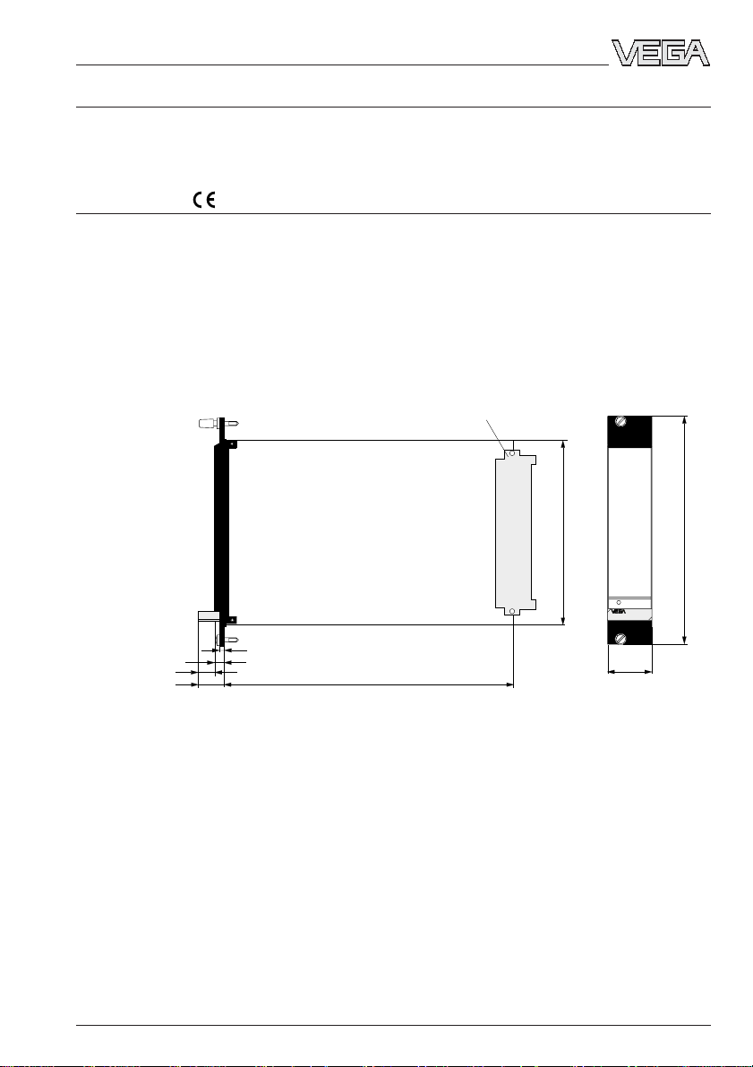
1.3 Dimensions
Circuit board 100 x 160 x 1,5
European size
Multiple plug
100
5 TE
128,4 (3 HE)
on
5,5
9
15
VEGATOR 536 Ex 5
3
162
25,4
Page 6

2 Mounting
VEGATOR can be either mounted with a
module in a carrier BGT 596 or in a single
housing type 505.
Mounting
Mounting single housing
Module (33)
for VEGATOR 536
Multipoint connector DIN 41 612, series F, 33pole (d, b, z) with coded pin and mounting
material for mounting in carrier BGT 596.
Module-Ex (33 Ex)
for VEGATOR 536 Ex
Multipoint connector DIN 41 612, series F, 33pole (d, b, z) with coded pin and mounting
material for mounting in carrier BGT 596 Ex.
Single housing
Plastic housing type 505 for single mounting
of signal conditioning instruments with an
instrument width of 5 TE (25,4 mm).
Mounting carrier
Mount the appropriate module (standard or
Ex-version) to your carrier BGT 596. Please
wire the connections of the multiple plug
according to the connection plans on the
following pages.
The multipoint connection is available as
follows:
- Wire-Wrap standard connection
1,0 x 1,0 mm
- Plug connection 2,8 x 0,8 mm
- Termi-Point standard connection
1,6 x 0,8 mm
- Soldering connection
- Screw terminals 2 x 0,5 mm
2
You can either screw the socket directly to
your mounting plate or plug on a carrier rail
(TS 35 x 7,5 acc. to EN 50 022 or TS 32 acc.
to EN 50 035). Connect the terminals of the
basic plate according to the connection plans
on the following pages. For further information
concerning mounting, see the operation instructions of the housing.
Transparent cover
The front plate of VEGATOR can be provided
with a lockable transparent cover to protect
the instrument against unauthorised adjustment. The cover is attached to the instrument.
For further information concerning mounting,
please see the operating instructions of the
carrier.
6 VEGATOR 536 Ex
Page 7

Mounting
Coding
The multiple plug of the instrument is provided with one or several coding holes to
avoid the interchanging of different instruments.
A fixed coded pin on the Ex-module ensures
that only the Ex-instrument can be inserted.
Two additional coded pins are attached to the
module to avoid the interchanging of different instruments. Insert the attached coded
pins into the appropriate holes on the
multipoint connector. The coded pins must be
inserted in the following positions:
Instrument Ex-coding
coding
VEGATOR 536 a17 / c7 ––
VEGATOR 536 Ex a17 / c7 c23
z b d
a c
o 1 o
o 3 o
o 5 o
o 7 o
o 9 o
o11o
o13o
o15o
VEGATOR 536
o17o
o19o
o21o
o23o
o25o
o27o
o29o
o31o
Fig. 2.8 Module 33 (Ex)
c7
c23
VEGATOR
Ex-coding
Ex-version
Ex-separating chamber
To ensure sufficient air and creeping distances, an Ex-separating chamber must be
mounted to the VEGATOR connections. Loop
the lines through the Ex-separating chamber
and connect the lines. Fasten the Ex-separating chamber with the lower hold screw.
Please note the operating instructions of the
BGT 596 carrier.
Mounting in carriers
When mounting VEGATOR with Ex-approval
in a carrier, you have to use a VEGA-Exmodule. Keep a distance of at least 10 mm (2
TE) to module cards of other manufacturers.
If you want to mount VEGATOR in the far left
position in the carrier, you have to mount a
blind cover of at least 20 mm (4 TE) first, and
then you can mount the instrument module.
2
on
VEGATOR
Blind cover
Protection in Ex-applications
In Ex-applications, a protection of IP 20
should be maintained. Cover the gaps or free
modules at the front by appropriate blind
covers.
Fig. 2.9
VEGATOR 536 Ex 7
Page 8

3 Electrical connection
Electrical connection
Danger
Please switch off the power supply before
starting connection. Connect mains voltage
according to the following diagram.
When connecting to the supply voltage or
reconnecting the sensor, the instrument
passes a function test. See also 5.1 Recurring test acc. to WHG.
In addition, two transistor outputs are available switching synchronously with the relays.
Reset of alarm functions
Module with multipoint connector acc. to
DIN 41 612 for carrier (rear view)
d b z
2
4
6
8
10
12
14
16
18
20
22
24
Ex-separating chamber
26
28
30
32
You can use the fail safe relay of VEGATOR
536 Ex as second level relay for a signaller
(horn etc.). To deactivate the connected
signaller (horn, lamp etc.) in case of a level
alarm (e.g. reaching of the max. permissible
level), an additional key (opener) can be
connected to VEGATOR 536 Ex. This key can
deactivate a level alarm. In case of failure
(e.g. line break), the alarm is not deleted.
When the key is connected, the fail safe relay
has the same function as the level relay, however the fail safe relay can be reset by
pressing the key for reset of alarm functions.
When, on reaching the max. level, e.g. an
acoustic warning system is activated, this
can be switched off by pressing the key for
reset of alarm functions. The second output
(level relay) still signals the reaching of the
max. level to the processing system.
Note
If very strong electromagnetic interferences
are expected, we recommend the use of
screened cable. The screening of the cable
must only be earthed on one sensor end. The
following connection plans show the
currentless condition.
Sensor 1
2 3
1
Sensor
channel 1
8 VEGATOR 536 Ex
Page 9

Electrical connection
Double-pole double-throw switch
(DPDT)
VEGATOR 536 Ex can also be operated with
double-pole double-throw switch output
(DPDT). The fail safe relay has the same
function as the level relay. To achieve this
function, the contacts z16 and z18 (reset of
alarm functions) must be bridged.
If you neither need the reset of alarm functions nor the function of the double-pole double-throw switch, the connections Z16 and
Z18 will be free.
Level relay
Level relay
Supply
voltage
Fail safe transistor
Level transistor
L1 (+)
N (–)
d b z
+–
2
6
10
12
+
16
–
18
+
20
–
22
24
3.1 Connection plan
All contacts in release condition
d b z
+–
2
6
10
12
+
16
–
18
+
20
–
22
24
28
+
30
–
32
+
–
L1 (+)
N (–)
Supply
voltage
Fail safe transistor
Level transistor
Fail safe relay
Level relay
Reset of
alarm
functions
28
+
+
–
30
–
32
VEGATOR 536 Ex 9
Page 10

4 Set-up
Indicating and adjustment elements
off
1
1 2 3 4 5 6
on
10
1 Connection plan
2 Lockable screw
3 Test key 1) channel 1
4 LED-level relay 1
5 LED-fault signal channel 1
9
1
2
3
TEST
4
5
on
VEGATOR
6
7
8
6 LED-supply voltage
7 Screw
8 Multiple plug
9 DIL-switch block for channel 1
10 Transparent cover
Set-up
1
536
1)
Recurring test acc. to WHG
In accordance with the type approval acc. to WHG (Z-65.11-154, Z-65.11-285) the recurring test acc. to
WHG can be carried out by pressing the test key on the VEGATOR signal conditioning instrument. The
sensor must neither be removed nor a response be triggered by filling the vessel. This applies to
VEGASWING 61Ex, 63Ex, 81AEx and 83AEx with two-wire oscillator SW E60ZEx, SW E82ZEx.
10 VEGATOR 536 Ex
Page 11

Set-up
Signal lamps
LEDs in the front plate show operation,
switching condition and failures.
Green
- Operating control lamp (6)
- Mains voltage on, instrument in operation.
Red
- Failure lamp (5)
- Failure on the individual sensor current
circuit by sensor failure or line defect.
- When the fail safe relay is denergised, the
red signal lamp lights.
Yellow
- Relay control lamp (4)
- The yellow signal lamp reacts depending
on the adjusted mode (A/B).
- The relay control lamps indicate the activated (energised) condition of the relay.
- A dark relay control lamp means that the
relay is in denergised condition.
DIL-switch block and potentiometer
The switch on and/or off delay can be adjusted independently with the switches 2 and
3. The switch on or off delay refers to the
switching conditioning of the relay and transistor outputs.
On the illustrated example mode A (max.
detection or overfill protection) is selected
(switch 1). The switch on delay is activated
(switch 3) and the integration time is adjusted
to 8 seconds (switch 4, 5 and 6).
sec
0
00
zaze26
sec
12
1 A/B-mode
2 Switch off delay
3 Switch on delay
4 Integration time +2 s
5 Integration time +6 s
6 Integration time +12 s
B- -
123456
A
The integration time can be adjusted appropriately with the switches 4,5 and 6. The
times of the activated time switches. When
the switch on (ze) and off delay (za) are
switched on at the same time, the adjusted
time applies to both delay modes.
Mode and integration time
A DIL-switch block with 6 switches (9) is
located on the circuit board of VEGATOR.
The individual switches are cordinated as
follows:
1 A/B-switch
A - max. detection or overfill protection
B - min. detection or dry run protection
2 Switch off delay
3 Switch on delay
4 Integration time 2 s
5 Integration time 6 s
6 Integration time 12 s
Switch123456
Time za ze 2 s 6 s 12 s
0,2 s A/B off off off off off
0,5 s A/B off off off
2 s A/B on off off
6 s A/B off on off
8 s A/B on on o f f
12 s A/B off off on
14 s A/B on off on
Optionally switch 2 and/
or 3 to "on“. The times
are valid for the appro-
priately adjusted delay
18 s A/B off on on
20 s A/B on on on
mode.
The mode can be adjusted (A - overfill protection or B - dry run protection) with
switch 1.
VEGATOR 536 Ex 11
Page 12

Set-up
Fault monitoring
The measuring system is monitored continuously. The following criteria are checked:
- two-wire line on line break and shortcircuit
- interruption of the connection line to the
piezoelements
- corrosion or damage of the tuning fork
(vibrating rod)
- break age of the tuning fork (vibrating rod)
- stop of vibration
- vibrating frequency too low
- corrosive medium penetrated into the sensor
Test key
A function test can be carried out with measuring systems in conjunction with two-wire
oscillators (VIB E50Z(Ex), SW E60ZEx,
SW E82ZEx).
The VEGATOR 536 Ex signal conditioning
instrument has an integral test key. The test
key is lowered in the front plate of the signal
conditioning instrument. Press the test key
with a suitable object (screwdriver, pen etc.).
By pressing the test the key measuring system is checked according to the following
criteria:
- switching function of the switching outputs
- potential separation of the outputs
- signal processing of the signal conditioning
instrument.
After pressing the test key, the complete
measuring system is checked for correct
function. During the test, the following operating conditions are simulated:
- fault signal
- empty signal (only with VEGASWING)
- full signal.
Check if all three switching conditions occur
in the correct sequence and the stated duration. If this is not the case, there is a failure in
the measuring system (see 5.2 Failure removal).
Please note that the connection instruments
are activated during the function test, which
means that you can check the correct function of the measuring system.
Due to this fault monitoring, the combination
of the following instruments corresponds to
classes 1 to 3 (AK 3) acc. to DIN 19 251.
AK 3 means that the system is fail safe.
- VEGASWING 61Ex, 63Ex, 81AEx, 83AEx
- SW E60ZEx, SW E82ZEx oscillator
- VEGATOR 536 Ex, 537 Ex, 636 Ex signal
conditioning instrument
VEGAVIB also passes the function test, however it is not approved acc. to WHG and
AK acc. to DIN 19 251.
Test course A-mode B-mode
1 Simulation of a fault signal (after release of the key approx. 3 s)
1)
Level relay deenergised
Fail safe relay deenergised
2 Simulation of an empty signal (approx. 1,5 s) only with VEGASWING
Level relay energised
Fail safe relay energised
3 Simulation of a full signal (approx. 1,5 s)
Level relay deenergised
Fail safe relay energised
4 Return to the actual operating condition (covered/uncovered)
1)
As long as the test key is pressed, the instrument remains at failure
12 VEGATOR 536 Ex
Page 13

Diagnosis
5 Diagnosis
5.1 Recurring test acc. to WHG
The implementation of the recurring test acc.
to WHG is regulated in the general type approval no. Z-65.11-154, (see item 8 of the
certificate).
Note the additional approvals when VEGASWING 81A and 83A are used as part of an
overfill protection acc. to WHG.
VEGASWING 61Ex, 63Ex, 81AEx and 83AEx
with signal conditioning instruments
VEGATOR 536 Ex, 537 Ex, 636 Ex meet the
fail safe requirements acc. to AK 3 in mode A
(overfill protection).
Recurring test acc. to WHG
In accordance with the type approval acc. to
WHG (no. Z-65.11-154, Z-65.11-285) the
recurring test acc. to WHG can be carried
out by pressing the test key on the
VEGATOR 536 Ex, 537 Ex, 636 Ex signal
conditioning instrument. The sensor must
neither be removed, nor should a response
be triggered by filling the vessel. This applies to VEGASWING 61, 63, 81AEx and
83AEx with SW E60ZEx and SW E82ZEx the
two-wire oscillator.
The implementation and the switching sequence of the function test is stated under
"Test key“ and the following table in the operating instructions of the appropriate
VEGATOR signal conditioning instrument.
5.2 Failure removal
Failure Measure, failure removal
The red failure- Check the sensor inputs on the following failures:
LED of the signal - shortcircuit on the input
conditioning instrument lights - sensor not correctly connected
- sensor line interrupted
- supply voltage too low
Check if the sensor is connected correctly.
- Failures on the sensor effecting a current change below 2 mA or
above 23 mA, cause a fault signal in the signal conditioning instruments.
Measure the current on the connection line to the sensor.
In normal condition, the terminal voltage of the sensor is at least 12 V.
4 … 20 mA 12 … 20 V
mA
+
–
Sensor
V
28
+
+
30
–
–
32
VEGATOR
series 500
Please note that in Ex-applications, the Ex-protection is not influenced by the measuring instruments.
VEGATOR 536 Ex 13
Page 14

Diagnosis
a. Current value < 2 mA
- Check the supply voltage on the connection line to the sensor. The
voltage should be approx. 17 … 20 V.
Should you measure a value below 17 V, then this shows a defect in
the signal conditioning instrument. In this case please send the instrument to VEGA for repair.
- Should the red failure lamp continue to light, separate the connection
line from the signal conditioning instrument and connect a resistor of
1 kΩ to the sensor inputs of the signal conditioning instrument.
If the failure lamp continues to light, the signal conditioning instrument
is defective. In this case please return the instrument to VEGA for
repair.
- Should the failure lamp extinguish, connect the signal conditioning
instrument again. Separate the sensor from the connection line and
connect a resistor of 1 kOhm instead .
- Should the failure lamp continue to light, the connection line probably
is interrupted. Check the connection line to the sensor.
- When the failure lamp extinguishes, the sensor is defective. Check
the connected sensor.
b.Current value > 22 mA
- Check all connections and the connection line to the sensor.
- Should the red failure lamp continue to light, separate the sensor from
the connection line and connect a resistor of 1 kΩ instead.
If the failure lamp extinguishes, the sensor is defective. Check the
connected sensor.
- Should the failure lamp continue to light, connect the sensor again.
Separate the signal conditioning instrument from the connection line
and connect a resistor of 1 kΩ to the sensor input instead.
- Should the failure lamp continue to light, the signal conditioning instrument is defective. In this case please send the instrument to VEGA
for repair.
- When the failure lamp extinguishes, there is probably a shortcircuit in
the connection line. Check the connection line to the sensor.
Malfunction during After pressing the test key, the switching conditions are not in the
function test correct sequence or of the correct duration, e.g. a full signal is not
triggered.
- Measure the line resistance
When the line is high-resistance, you have to reduce it to a standard
resistor by appropriate measures. Check for example terminals and
cable connections for corrosion.
14 VEGATOR 536 Ex
Page 15

VEGATOR 536 Ex 15
Page 16

VEGA Grieshaber KG
Am Hohenstein 113
77761 Schiltach
Germany
Phone 07836 50-0
Fax 07836 50-201
E-mail info@de.vega.com
www.vega.com
ISO 9001
The statements on types, application, use and operating conditions
of the sensors and processing systems correspond to the actual
knowledge at the date of printing.
Technical data subject to alteration.
23460-EN-030718
 Loading...