

Page 1

TH LINK
Doc. Version 1.1
Installation Guide
English
Page 2

Dear Customer,
This installation Guide will help you to install the hardware. If you have any
further questions, please contact our Technical Support:
Trebing & Himstedt Prozeßautomation GmbH & Co. KG
Technical Support
Wilhelm-Hennemann-Str. 13
19061 Schwerin | Germany
Phone: +49 385 39572-500
Fax: +49 385 39572-22
E-mail: support@t-h.de
Internet: http://www.t-h.de
All brand and product names are trademarks or registered trademarks of
their respective owners.
© Trebing & Himstedt Prozeßautomation GmbH & Co. KG
All rights reserved, including rights to the translation. This inst allation guide
as well as extracts thereof may be duplicated or forwarded to third parties
only after written permission has been obtained from Trebing & Himstedt
Prozeßautomation GmbH & Co. KG.
The installation guide is intended for use by the owner of the
Trebing
product owner's operating personnel. It must not be passed on or made
accessible to third parties. If this installation guide should refer directly or
indirectly to laws, regulations or directives (e.
from them, Trebing & Himsted t Prozeßautomation GmbH & Co. KG cannot
assume responsibility for the correctness, completeness or up-to-date
nature of the same. If required, we recommend obtaining the respectively
valid versions of the complete regulations or directives for your own work.
We reserve the right to make technical changes.
& Himstedt Prozeßautomation GmbH & Co. KG product or the
g. DIN, VDE, ...) or quote
Doc. Version 1.1 | May 2012
Page 3

Content
About this Installation Guide ....................................................................4
Intended use .............................................................................4
Explanation of safety instructions .............................................4
Menu and keyboard commands ................................................5
For your safety .........................................................................................5
Performance and functioning ...................................................................8
Features ....................................................................................8
Scope of delivery ......................................................................8
Configuration requirements .......................................................9
Ethernet network presettings ....................................................9
Design of the TH LINK ...........................................................................10
Connections and indicating elements .....................................12
Mounting .................................................................................12
Start-up guideline ..................................................................................13
Note regarding the application software ..................................13
Installing the TH LINK ............................................................................14
Installing the TH LINK .............................................................14
Uninstalling the TH LINK .........................................................15
Connecting to Ethernet ..........................................................................15
Connecting the power supply ................................................................16
Configuring the TH LINK in the Ethernet network .................................18
Establish a connection to the TH LINK ...................................18
User administration .................................................................20
TH LINK description ................................................................20
Network configuration .............................................................20
TH SCOPE settings ...............................................................................25
Measurement ..........................................................................26
Alert .........................................................................................26
Parameter distribution .............................................................26
Connecting the PROFIBUS ...................................................................28
Bus terminating resistors .........................................................30
Setting PROFIBUS parameters ..............................................30
Firmware update ....................................................................................31
Troubleshooting .....................................................................................32
Technical data .......................................................................................34
General conditions .................................................................................35
Page 4
About this Installation Guide
About this Installation Guide
Please read this installation guide carefully prior to installation. It
facilitates installation and setup of your system and provides you
with important information.
Intended use
The TH LINK is designed to be used as an interface between
PROFIBUS and Ethernet networks. Any other use is deemed
non-intended use.
Explanation of safety instructions
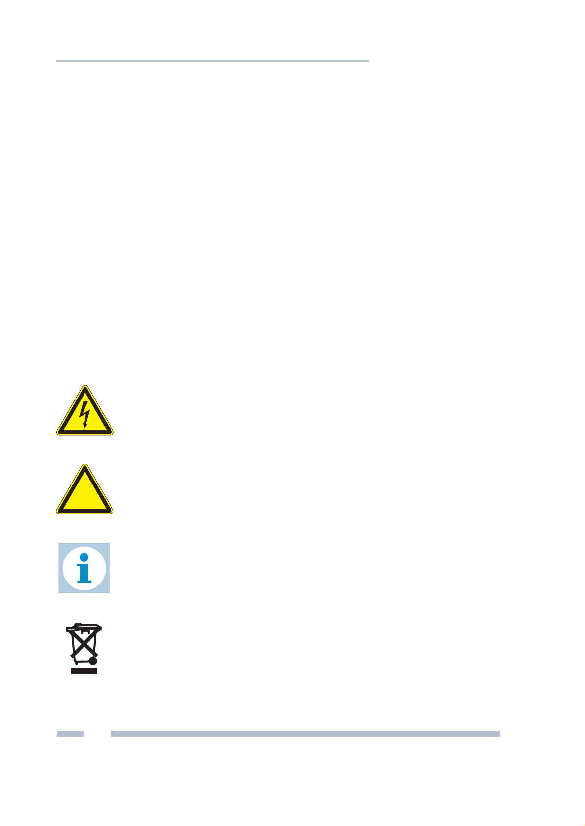
The following symbols and signal words used are intended to
draw your attention to special situations:
Danger!
Warning of personal injury from high voltage.
Warning!
Warning of damage to the device.
Note!
Useful tips.
4
Disposal
Notes on disposal.
Trebing & Himstedt Prozeßautomation GmbH & Co. KG | TH LINK
Page 5
For your safety
Menu and keyboard commands
The following conventions apply to menu and keyboard
commands:
Courier font
<Key> Press the indicated key.
Window names, menu items, fields
and descriptions of combo boxes,
check boxes, radio buttons and icons.
For your safety
Strictly observe the following safety instructions before
connecting the device:
Danger!
Small objects or liquids must not enter the case
of the TH
slots). This may damage the device.
Never cover the ventilation slots on the device.
LINK (e. g. through the ventilation
Warning!
Never open the case of the TH LINK or carry out
any mechanical modifications on the device.
Otherwise, this may lead to damages on the
device as well as to loss of warranty.
TH LINK | Trebing & Himstedt Prozeßautomation GmbH & Co. KG
5
Page 6

For your safety
Warning!
The TH LINK contains electronic components
sensitive to electrostatic discharges. Damages
due to electrostatic discharge can lead to
premature failure of components or intermittent
faults at a later stage.
Before installing the TH LINK, divert the
electrostatic discharge away from your body and
the tools used.
– Carefully plan the integration of the TH LINK into an existing
system and ensure proper function of the system after
installation.
– The TH LINK may only be installed or uninstalled by qualified,
trained electrical engineering personnel.
When installing the TH LINK, observe the regulations for
handling electric components in accordance with VDE 0100. In
addition, you must also observe the valid safety and accident
prevention regulations (UVV) when operating the device within
the jurisdiction of the Federal Republic of Germany.
– Observe the IEC 61158 standard.
– Always install the TH LINK on a suitable top-hat rail (mounting
rail).
– Cables used for the connection must not apply any mechanical
forces to the TH
LINK.
6
Trebing & Himstedt Prozeßautomation GmbH & Co. KG | TH LINK
Page 7

For your safety
– High temperature differences between the storage site and
installation site can result in condensation within the case,
which may cause the TH
LINK to become damaged.
In case of high temperature differences, please wait at least
three hours before operating the TH
LINK.
– Lock the connected plug (PROFIBUS) using the srew
connections intended for this purpose.
Disposal
The TH LINK must be disposed of separately
from normal household waste in accordance
with the 2002/96/EC (WEEE) directive.
TH LINK | Trebing & Himstedt Prozeßautomation GmbH & Co. KG
7
Page 8

Performance and functioning
Performance and functioning
The TH LINK provides access to the communication system and
connects the higher-level network structure with the field level. It
forms the basis for the Trebing + Himstedt products TH SCOPE,
PROFIBUS Scope, Trebing + Himstedt DTM Library, TACC and
TH OPC Server DP.
The TH LINK is quick to assemble/install and to put into
operation. The delivered default configuration allows start-up in
only a few minutes. In order to prevent network disruptions by
unauthorized configuration changes, all configuration functions
are protected by user administration.
The TH LINK includes the free-of charge TH SCOPE easy.
Features
– Connection between higher-level network and field level
– Access to the PROFINET/Industrial Ethernet network
– Basis for TH SCOPE, PROFIBUS Scope, Trebing + Himstedt
DTM Library, TACC and TH OPC Server DP
– Access protection through integrated user administration
– TH SCOPE easy preinstalled
Scope of delivery
–TH LINK
– Installation Guide
– Release Note (per download at www.t-h.de)
8
Trebing & Himstedt Prozeßautomation GmbH & Co. KG | TH LINK
Page 9

Performance and functioning
Configuration requirements
(not included in the scope of delivery)
– Web browser with Adobe Flashplayer 10.0 or higher
– Enabling port 80 and IP 224.0.5.128 port 2364 UDP
– Application software for PROFIBUS configuration
Ethernet network presettings
–The TH LINK is preset to Ethernet network operation with a
DHCP server. No Ethernet network configuration settings are
required in this operating mode.
– In case of manual allocation of IP addresses the TH LINK has
the following standard IP configuration:
IP address 169.254.0.1
Subnet mask 255.255.0.0
Default gateway 0.0.0.0
TH LINK | Trebing & Himstedt Prozeßautomation GmbH & Co. KG
9
Page 10

Design of the TH LINK
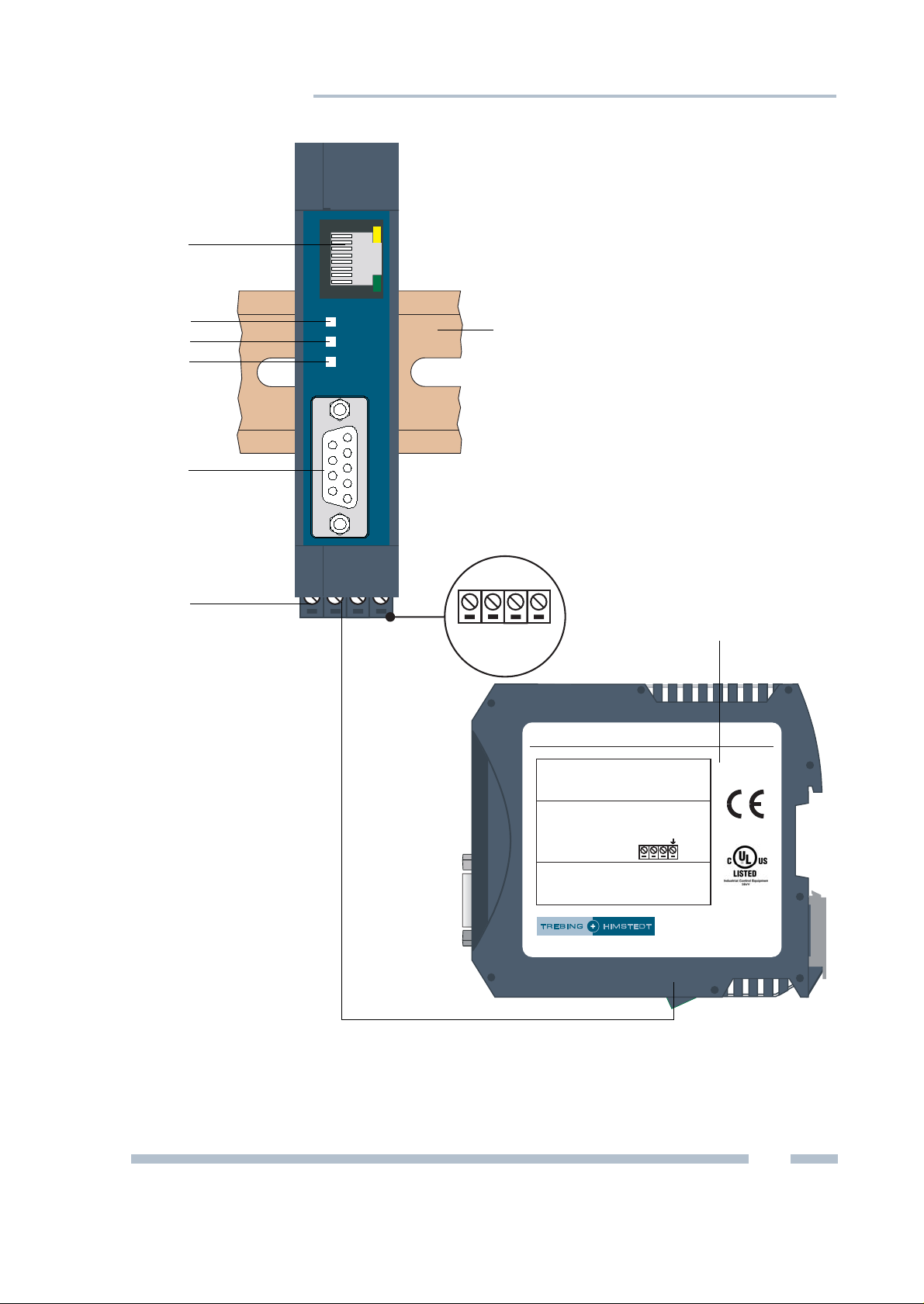
Design of the TH LINK
(see figure 1)
1 Ethernet interface
2LED ETH
3LED RUN
4LED BUS
5 PROFIBUS interface
6 Terminal strip for power supply
7 Type label
8 Top-hat rail (not included in the scope of delivery)
10
Trebing & Himstedt Prozeßautomation GmbH & Co. KG | TH LINK
Page 11
Design of the TH LINK
TH LINK
Trebing & Hi mstedt Prozeßau tomation GmbH & Co. KG
www.t-h.de
Made in Germany
Part No.: 10003006
HW-Release: 2.0
Serial No.: 000000
Temperature: 0 to +50 °C
Current: 190 mA max.
Power Supply: 19.2 to 28.8 V DC
ETH: Ethernet (green/red)
RUN: OK (green) | Error (red)
BUS: PROFIBUS (green/red)
24 V DC
+–
[1]
[2]
[3]
[5]
[7]
[4]
[6]
[8]
ETH
RUN
BUS
TREBING + HIMSTEDT
PROFIBUS
A B C D
Fig. 1: TH LINK (front and side view)
TH LINK | Trebing & Himstedt Prozeßautomation GmbH & Co. KG
11
Page 12

Design of the TH LINK
Connections and indicating elements
[1] Ethernet interface: RJ-45 (10Base-T/100Base-TX)
– LED lights yellow: Ethernet data communication
– LED lights green: physical connection available
[2] LED ETH
– ETH lights red: first start phase
– ETH flashes red: boot procedure
– ETH lights red or flashes red or green in case of an error:
internal firmware failure
– ETH lights green: connection to application via Ethernet
[3] LED RUN
– RUN lights red: internal failure identified
– RUN lights green: 24V power supply is fed
[4] LED BUS
– BUS lights green: device communicates active via
PROFIBUS
[5] PROFIBUS interface: D-Sub socket
[6] Terminal strip for +24 VDC power supply
– A: 24 V (+)
–B: 0 V (-)
– C: not assigned
– D: Earth conductor
Mounting
[8] 35 mm DIN top-hat rail (not included in the scope of
delivery)
12
Trebing & Himstedt Prozeßautomation GmbH & Co. KG | TH LINK
Page 13

Start-up guideline
Start-up guideline
The following steps are required for start-up:
1. Install the TH LINK (see "Installing the TH LINK" on
page 14).
2. Connect to Ethernet (see "Connecting to Ethernet" on
page 15).
3. Connect to the power supply (see "Connecting the power
supply" on page 16)
4. Configure Ethernet (see "Configuring the TH LINK in the
Ethernet network" on page 18)
Note!
To set the IP address manually you must
connect your PC/notebook to the TH
crossover cable.
5. Connect the PROFIBUS (see "Connecting the PROFIBUS"
on page 28).
6. If you use the TH LINK as a class 2 master you have to
configure PROFIBUS parameters of the TH
application software (
on page 30).
see "Setting PROFIBUS parameters"
LINK via
LINK using an
Note regarding the application software
For operating the TH LINK as a class 2 master, an application
software with the appropriate drivers is required. For more
information about purchasing and operating the software please
check our website at http://www.t-h.de or contact our sales
department (sales-ic@t-h.de).
TH LINK | Trebing & Himstedt Prozeßautomation GmbH & Co. KG
13
Page 14

Installing the TH LINK
TH LINK
Trebing & Himstedt Prozeßau tomation GmbH & Co. KG
www.t-h.de
Made in Germany
Part No.: 10003006
HW-Release: 2.0
Serial No.: 000000
Temperature: 0 to +50 °C
Current: 190 mA max.
Power Supply: 19.2 to 28.8 V DC
ETH: Ethernet (green/red)
RUN: OK (green) | Error (red)
BUS: PROFIBUS (green/red)
24 V DC
+–
TH LINK
Trebing & Hi
m
stedt Prozeßauto
mation GmbH & Co . KG
www.t-h.de
Made in Germany
Part No.: 10003006
HW-Release: 2.0
Serial No.: 000000
Temperature: 0 to +50 °C
Current: 190 mA max.
Power Supply: 19.2 to 28.8 V DC
ETH: Ethernet (green/red)
RUN: OK (green) | Error (red)
BUS: PROFIBUS (green/red)
24 V DC
+
–
[1]
[3]
[2]
[4]
Installing the TH LINK
Installing the TH LINK
Warning!
Above and below the TH LINK, a minimum of 2
inches head space for heat dissipation needs to
be available.
Fig. 2: Installing and removing of the TH LINK
1 Device with notch on top-hat rail
2 Top-hat rail
3 TH LINK on top-hat rail
4Stop lever
Place the notch of the TH LINK on the top-hat rail and move the
LINK downward until the stop lever locks into place on the
TH
top-hat rail.
14
Trebing & Himstedt Prozeßautomation GmbH & Co. KG | TH LINK
Page 15

Connecting to Ethernet
Uninstalling the TH LINK
1. Remove the connected supply and signal lines (Ethernet,
PROFIBUS, voltage).
2. Place the screwdriver into the stop lever on the TH LINK
see figure 2).
(
3. Press the screwdriver in the direction of the TH LINK and
simultaneously swing the device off the top-hat rail.
Connecting to Ethernet
– Insert the patch cable plug (RJ-45, not included in the scope of
delivery) into the Ethernet socket (
TH LINK until the plug locks into place.
– The green LED on the Ethernet socket lights as soon as the
TH
LINK is energized and an Ethernet network is available.
see figure 1 no. [1]) on the
TH LINK | Trebing & Himstedt Prozeßautomation GmbH & Co. KG
15
Page 16

Connecting the power supply
Connecting the power supply
Danger!
Electrical voltage.
Only qualified electricians are allowed to work
on the electrical equipment.
Danger!
Incorrect TH LINK earthing can cause injury to
personnel or device damage. Ensure correct
and proper earthing of the TH
Warning!
Reverse polarity in the power supply can
damage the device. Make sure the power
supply is connected with correct polarity.
LINK.
16
Trebing & Himstedt Prozeßautomation GmbH & Co. KG | TH LINK
Page 17

Connecting the power supply
+24 V not assigned0 V
Earth conductor
Fig. 3: Terminal strip for power supply on the TH LINK
1. Connect the cable of a 24 V power supply and the earth
conductor (earth terminal) to the terminal strip on the device.
The terminal strip can be plugged and lifted out for
installation using a screwdriver.
2. Switch on the power supply. The LED RUN is green and the
LED ETH flashes red until the TH
LINK's initiation procedure
is completed. Afterwards only the LED RUN lights green.
17
TH LINK | Trebing & Himstedt Prozeßautomation GmbH & Co. KG
Page 18

Configuring the TH LINK in the Ethernet network
Configuring the TH LINK in the Ethernet
network
Establish a connection to the TH LINK
1. Connect the TH LINK to a PC/notebook via crossover cable.
The PC/notebook has to be in the same subnet as the
TH
LINK.
2. Start a web browser on your PC/notebook.
3. Enter the IP address http://169.254.0.1 and press
<Enter>. The TH SCOPE website is loaded.
Login
1. Click on Login.
2. Enter the password. The default password is the six-figure
serial number of the device.
at the case
3. Click on OK.
Note!
We recommend changing the password after
login (
Note!
Log out after changing settings (Click on
Logout). Otherwise you have to wait about 10
minutes to get access to this TH
or at Info.
see "User administration" on page 20).
You can find it on the type label
LINK, if you
18
have left the site or closed the browser.
Trebing & Himstedt Prozeßautomation GmbH & Co. KG | TH LINK
Page 19

Configuring the TH LINK in the Ethernet network
Settings
Click on settings and then on TH LINK.
Here you can change the settings for user administration,
LINK description and network configuration.
TH
Fig. 4: TH LINK settings
Note!
For detailed information about each setting,
click on the question mark.
TH LINK | Trebing & Himstedt Prozeßautomation GmbH & Co. KG
19
Page 20

Configuring the TH LINK in the Ethernet network
User administration
Here you can change the password. Proceed as follows:
1. Enter the old password.
2. Select a new password and confirm it by re-entering.
3. Finally, click Change password.
TH LINK description
Here you can enter a tag name, a location, an installation date
and a description of the TH
LINK.
Network configuration
Here you have to set the operation mode and the configuration
method. You can also make time settings.
Operation mode
Select at network configuration the operation mode of
the TH
In the operation mode Passive PROFIBUS station the
TH
needs no own PROFIBUS address.
In the operation mode Active/Passive PROFIBUS station
the TH
LINK.
LINK is a passive station in the bus. Therefore the TH LINK
LINK can be used as a class 2 master in connection with
an external master application (FDT or Emerson's AMS Suite).
The TH LINK is passive until a PROFIBUS address is set in the
master application and the communication is started. Then the
TH
LINK is an active station.
20
Trebing & Himstedt Prozeßautomation GmbH & Co. KG | TH LINK
Page 21

Configuring the TH LINK in the Ethernet network
Configuration method (DHCP/Manual)
There are two connecting options to choose from, depending on
your network:
– Connection in an Ethernet network with DHCP server –
automatic and dynamic allocation of IP addresses (connection
with patch cable via hub or switch)
– Connection in an Ethernet network with manual IP address
assignment (peer-to-peer) – manual allocation of IP addresses
(connection with crossover cable)
Connection in a network with DHCP
(Dynamic Host Configuration Protocol)
The TH LINK is preset to network operation with a DHCP server
and in this case it is automatically assigned an IP address.
Therefore, no further configuration settings are necessary.
Note!
If you connect to Ethernet network with the
power supply already connected, the DHCP
may fail to be identified. The routine for the
DHCP identification only runs during TH
start-up.
LINK
Briefly switch off the power supply for a new
DHCP identification.
TH LINK | Trebing & Himstedt Prozeßautomation GmbH & Co. KG
21
Page 22

Configuring the TH LINK in the Ethernet network
Connection in a network with manual IP address assignment
If you use the TH LINK in an Ethernet network without DHCP
server, you need the following for configuration:
– TCP/IP settings for this network
– a PC/notebook with a web browser and Adobe Flash Player
– a crossover cable between PC/notebook and TH LINK (peer-
to-peer connection)
Note!
Always notify your system administrator prior to
allocating IP addresses.
If you set an address already assigned, other
devices in the network may be deactivated and
communication may be affected.
Note!
The PC/notebook must be in the same subnet
as the TH
LINK.
The TH LINK has the following manual default IP addresses
(default settings at the time of delivery):
IP address 169.254.0.1
Subnet mask 255.255.0.0
Default gateway 0.0.0.0
22
Trebing & Himstedt Prozeßautomation GmbH & Co. KG | TH LINK
Page 23

Configuring the TH LINK in the Ethernet network
Setting new IP and network addresses
1. Change the Configuration method from DHCP to
Manual (
see figure 5).
Fig. 5: Setting IP and network addresses
2. Enter the new IP address.
Note!
Note down the set IP address. You can only
access the TH
LINK by using this IP address.
3. Enter the new addresses for Subnet mask and Default
gateway.
23
TH LINK | Trebing & Himstedt Prozeßautomation GmbH & Co. KG
Page 24

Configuring the TH LINK in the Ethernet network
4. If you want to use a DNS server, select Yes and enter the
DNS server IP addresses.
5. Click on the floppy disk sign to save the settings.
Thereafter the TH LINK restarts and you will be logged out
as administrator automatically.
Note!
If you use several TH LINK, you can facilitate
the configuration by using the parameter
distribution (
see "Parameter distribution" on
page 26).
Checking the connection to the TH LINK
You can check the TH LINK in the network when:
–the TH LINK is integrated into the Ethernet network
–the TH LINK is energized
– the PC/notebook is in the same subnet
Procedure
Start a web browser on your PC/notebook.
– For DHCP: Enter the host name (basic setting:
THLINK_+serial number) found on the TH LINK's type label
(e.g.:
THLINK_000075) and press <Enter>.
– Manual IP configuration: Enter the set IP address (basic
setting: 169.254.0.1) and press <Enter>.
The TH SCOPE website is displayed in the web browser.
24
Trebing & Himstedt Prozeßautomation GmbH & Co. KG | TH LINK
Page 25

TH SCOPE settings
TH SCOPE settings
Click on settings > TH SCOPE.
Here you can change the settings for measurement, alert and pa-
rameter distribution.
Fig. 6: TH SCOPE settings
Note!
Log in as administrator to change settings (see
"Login" on page 18).
Note!
For detailed information about each setting,
click on the question mark.
TH LINK | Trebing & Himstedt Prozeßautomation GmbH & Co. KG
25
Page 26

TH SCOPE settings
Measurement
The measurement settings include among other settings for baud
rate and Start/Stop of the TH SCOPE measurement.
Alert
The alert settings include among other settings for activating the
email alert function, when an email should be sent, SMTP server ,
subject, email sender and receiver.
Parameter distribution
The parameter distribution serves for a quick and easy
configuration of several TH
be set a parameter provider. All other units can request the
parameters from this TH
LINK. Therfore one TH LINK has to
LINK.
Set parameter provider
The TH LINK from which all other units can take over the set
parameters is called parameter provider.
Select the distribution role Parameter provider and save your
settings by clicking on the
Note!
Only one "parameter provider" is allowed in the
entire network.
In TH SCOPE network overview > network
list
the parameter provider is marked with the
floppy disk sign.
26
following icon.
Trebing & Himstedt Prozeßautomation GmbH & Co. KG | TH LINK
Page 27

TH SCOPE settings
Apply parameters
By default all TH LINK are set as parameter receiver. Before
taking over the parameters of a TH LINK, make sure that this
TH LINK is set as a parameter provider.
Click on Request at Apply parameters to query the parameters from the parameter provider.
Thereafter the TH LINK restarts and you will be logged out as
administrator automatically.
Parameters
The following data will be assigned:
TH LINK TH SCOPE
– Default language
– Operation mode
–DNS server
– Time server settings /
PC system time
– Type of measurement
– Measurement
– Slave has never responded
– Sorting of diagnostics list
– Alert settings
TH LINK | Trebing & Himstedt Prozeßautomation GmbH & Co. KG
27
Page 28

Connecting the PROFIBUS
Connecting the PROFIBUS
The 9-pin D-Sub socket is used for connection.
– Only use standard PROFIBUS plugs and cables.
– Wire the PROFIBUS plug according to the details for pin
assignment (
– If the TH LINK is installed at the beginning or end of the
PROFIBUS cable segment, you will need a bus terminating
resistor (
see "Technical data" on page 34).
see "Bus terminating resistors" on page 30).
Warning!
Do not use branch lines for the connection.
If local conditions do not allow a direct
connection, use a repeater (connection
according to PROFIBUS norm).
1. Attach the PROFIBUS connector onto the PROFIBUS
socket on the TH
2. Secure the plug with screws.
3. Switch the switch for the bus terminating resistor on the
LINK.
PROFIBUS connector to the required position (ON/OFF).
28
Trebing & Himstedt Prozeßautomation GmbH & Co. KG | TH LINK
Page 29

Connecting the PROFIBUS
PROFIBUS DP
PROFIBUS PA
HART
Diagnostic
Repeater
TH LINK
PA Link Remote IO
Field Device
Field Device
Field Device
Field Device
PLC
Ethernet
TH LINK
TH LINK
[1] [2]
Fig. 7: Interface connection possibilities in the PROFIBUS network
[1] Connection behind a master (SPS)
[2] Connection in a separate PROFIBUS segment behind a repeater.
TH LINK | Trebing & Himstedt Prozeßautomation GmbH & Co. KG
29
Page 30

Connecting the PROFIBUS
Data+
(Pin 3)
Data–
(Pin 8)
GND
DC/DC
(Pin 5)
[2] [3][1]
+5 V
DC/DC
(Pin 6)
Bus terminating resistors
Terminations of a PROFIBUS segment must each be terminated
with a bus terminating resistor. Use standardised plugs
containing terminating resistors.
Fig. 8: Bus termination configuration (see standard IEC 61158)
[1] 390 Ω Pull-up resistance from pin 3 to positive supply volt age at pin 6
[2] 220
[3] 390
Ω Cable terminating resistor between pin 3 and pin 8
Ω Pull-down resistance from pin 8 to data reference potential at
pin 5
Setting PROFIBUS parameters
Depending on the used application software (not included in the
scope of delivery), the TH
an own station address) or an active station (class 2 PROFIBUS
master).
The setting of the PROFIBUS parameters is only required, if you
use the TH
LINK as a class 2 master in the operation mode
active/passive PROFIBUS station.
are given by the class 1 master.
LINK can be a passive station (without
The PROFIBUS parameters
30
Trebing & Himstedt Prozeßautomation GmbH & Co. KG | TH LINK
Page 31

Firmware update
Firmware update
Firmware updates for the TH LINK are available free of charge at
our website, www.t-h.de. Proceed as follows.
1. Y ou have to log in as administrator to perform a firmware update (see "Login" on page 18).
2. Click on settings and then on Firmware update.
3. Check if the requirements for a firmware update are met.
Therefore the measurement and the external applikation
must be stopped.
4. Download the latest firmware version from www.t-h.de and
save it in your local directory.
5. Click on [...] and select the firmware.
6. Click on Start.
Note!
Do not not turn off the power, during the entire
firmware update process! After the firmware
update the TH
LINK restarts automatically.
Fig. 9: Firmware update
TH LINK | Trebing & Himstedt Prozeßautomation GmbH & Co. KG
31
Page 32

Troubleshooting
Troubleshooting
TH LINK is not found in the Ethernet network
– Check the power supply (LED RUN must light green).
– Check for correct connection (RJ-45, see "Connecting to
Ethernet" on page 15).
– The TH LINK is preset to network operation with a DHCP
server (IP address for the TH
server). If your network server does not support DHCP, you
need to set the IP address for the TH
(see "Connection in a network with manual IP address
assignment" on page 22).
– When a crossover cable is used between PC/notebook and
LINK, both devices must be in the same subnet.
TH
PROFIBUS network is not found
TH LINK as Passive PROFIBUS station:
– Check for proper connection (see "Connecting the
PROFIBUS" on page 28) and switch at Settings >
TH SCOPE > Measurement the baud rate on Automatic
detection.
LINK is assigned by the DHCP
LINK yourself
TH LINK as Active/Passive PROFIBUS station:
– Check the PROFIBUS parameters for the used TH LINK (see
application software, not included in the scope of delivery).
Each station has its own station address, which can only be
assigned once in the network.
32
Trebing & Himstedt Prozeßautomation GmbH & Co. KG | TH LINK
Page 33

Troubleshooting
LED ETH lights red or flashes red or green in case of failure
or
LED RUN lights red – internal error
– Internal error or defect: Please contact the Technical Support:
Trebing & Himstedt Prozeßautomation GmbH & Co. KG
Technical Support
Wilhelm-Hennemann-Str. 13
19061 Schwerin | Germany
Phone: +49 385 39572-500
Fax: +49 385 39572-22
E-mail: support@t-h.de
Internet: http://www.t-h.de
TH LINK | Trebing & Himstedt Prozeßautomation GmbH & Co. KG
33
Page 34

Technical data
15
69
Technical data
Electrical data
Nominal supply voltage
(limit values)
Current consumption max. mA 190
Protection class IP 20
Operating conditions
Ambient temperature range °F 32...122
Relative humidity % 20...80 (no condensation)
Case data
Dimensions W × H × D in 0.9 x 3.9 x 4.5
Weight (approx.) l 0.3
PROFIBUS interface
Interface Type RS 485
VDC 24 (19.2...28.8)
Transmission rate bps 9,600...12M
Sub-D plug pin assignment Pin 1
Pin 2
Pin 3
Pin 4
Pin 5
Pin 6
Pin 7
Pin 8
Pin 9
Other
Ethernet connection Type RJ-45 (10Base-T/100Base-TX)
Certificates CE, UL
not assigned
not assigned
B line data+ (RxD/TxD-P)
RTS
GND (0 V)
Potential (+5 VDC)
not assigned
A line data– (RxD/TxD-N)
not assigned
34
Trebing & Himstedt Prozeßautomation GmbH & Co. KG | TH LINK
Page 35

General conditions
General conditions
Right to make additions or alterations
Trebing & Himsted t Prozeßautomation GmbH & Co. KG reserves the right
to continue development of this installation guide and the properties of the
hardware and software at any time, also without releasing information
about this or about alterations prior to doing so.
Exclusion from liability
Trebing & Himstedt Prozeßautomation GmbH & Co. KG assumes no
warranty for proper function of the hardware and software in all conceivable
situations. Currently available technical means do not enable the
development of software which is completely free of errors in all conceivable
applications. Trebing & Himstedt Prozeßautomation GmbH & Co. KG does
not accept any liability for damages, both direct and indirect, arising from the
use of the hardware and software and the information contained in this
manual.
Duty to monitor products
As part of our duty to monitor products, we strive to warn about dangers
we have identified which can result from the interaction of hardware and
software and product use with third-party products. Monitoring is only
possible if we receive sufficient information from our customers on the
planned application(s) and the existing hardware and software
components. As a result of the complex interactions, it is no longer
possible for us to accurately identify all dangers and to check the effect on
the overall system and in particular on our hardware and software, if the
conditions of application have changed and/or hardware or software has
been exchanged. This installation guide does not describe all technical
characteristics of the hardware and software and their variants. For more
information please contact Trebing & Himstedt Prozeßautomation GmbH
& Co. KG.
Warranty
Our products are subject to warranty in accordance with our general
business and delivery terms.
TH LINK | Trebing & Himstedt Prozeßautomation GmbH & Co. KG
35
Page 36

Doc.Nr . 10003010 © Trebing & Himstedt Prozeßautomation GmbH & Co. KG
 Loading...