

Page 1
Level and Pressure
Operating Instruction
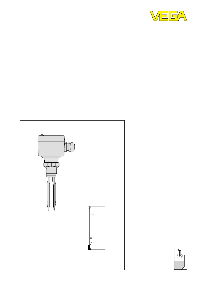
VEGASWING 81, 83 fail safe
and signal conditioning instrument VEGATOR 526 Ex
VEGATOR 526 Ex
on
Page 2

Contents
Safety information ........................................................................ 2
1 Product description
1.1 Function and configuration .................................................. 3
1.2 Approvals ............................................................................. 5
1.3 Recurring test acc. to WHG ................................................. 6
1.4 Technical data and dimensions ........................................... 7
2 Mounting
2.1 VEGASWING ...................................................................... 13
3 Electrical connection
3.1 VEGASWING ...................................................................... 18
3.2 Connection plan VEGATOR 526 Ex ................................... 19
4 Set-up
4.1 VEGASWING 8… W5␣ Ex.C................................................. 22
4.2 Signal conditioning instrument VEGATOR 526 Ex ............ 23
Contents
5 Diagnosis
5.1 Failure removal ................................................................... 26
Safety information
The described module must only be installed
and operated as described in this operating
instruction. Please note that other action can
cause damage for which VEGA does not take
responsibility.
2 VEGASWING 81 W5 Ex.C, 83 W5 Ex.C fail safe
Page 3

Product description
1 Product description
1.1 Function and configuration
VEGASWING 81␣ W5␣ Ex.C and 83␣ W5␣ Ex.C fail
safe vibrating level switches detect levels of
liquids with a viscosity of 0,2 mPa␣ s to
10.000␣ mPa␣ s and a density ≥␣ 0,5␣ g/cm3. The
modular construction enables the use in
vessels, tanks and pipelines. Typical
applications are overfill protections according
to AK5.
Due to the simple and rugged measuring
system, VEGASWING can be used virtually
unaffected by the chemical and physical
features of the liquid. It operates also under
arduous conditions such as turbulences, air
bubbles, foam generation, build-up and
changing medium.
With the mechanical connections thread and
flange, VEGASWING 81␣ W5␣ Ex.C or
83␣ W5␣ Ex.C can be used in manifold
applications.
For the use in very aggressive products,
Hastelloy C4 and ECTFE (halar), Säkaphen
and enamel-coatings are used for
VEGASWING 81 and 83.
VEGASWING 83 F… can be coated with
enamel or up to 1200 mm and Säkaphen up to
4␣ m tube length.
Function
The tuning fork is piezoelectrically energized
and vibrates at a resonance frequency of
approx. 400␣ Hz. A second piezoelectrical
element measures the resonance frequency of
the tuning fork. When the tuning fork is
covered with the medium, the resonance
frequency changes. This frequency change is
continuously detected by the integral oscillator
and converted into a switching command by
the connected signal conditioning instrument.
With a mode switch you can determine the
switching mode (overfill protection or
protection against dry running of pumps).
Note that VEGASWING 8…␣ W␣ Ex.C only meets
the fail safe requirements in mode A (overfill
protection).
Fail safe / Self-monitoring
A special feature of this instrument
configuration VEGATOR 526␣ Ex with
VEGASWING 81␣ W5␣ Ex.C or 83␣ W5␣ Ex.C is the
integral self-monitoring. It is based on a redundant microcomputer system in the signal
conditioning instrument and includes the
complete measuring chain from the tuning fork
via the oscillator, the two-wire line as well as
the signal conditioning instrument (see also
“1.3 Recurring test acc. to WHG“).
For medium temperatures of more than 100°C
to 130°C VEGASWING 81␣ W5␣ Ex.C and
83␣ W5␣ Ex.C must be equipped with a
temperature adapter.
VEGASWING 81 W5 Ex.C, 83 W5 Ex.C fail safe 3
The self-monitoring includes two routines:
- the permanent monitoring
- the cyclical self-test.
During the permanent monitoring the signal
conditioning instrument induces the oscillator
of the sensor to carry out a test cycle in
960␣ msec-cycle. Hence defined test signals
are transmitted via the two-wire line to the
signal conditioning instrument. Probable errors
in the sensor electronics as well as line break,
shortcircuit and mechanical damages on the
fork are signalled via these test signals.
Page 4

Product description
During the cyclical self-test safety relevant
components and procedures (e.g. level relay,
CPU) are checked in a very narrow time
pattern in the signal conditioning instrument.
The fault monitoring of the level relay is made
without interruption of the circuit of connected
systems.
The integral fault monitoring detects:
- interruption of the connection line to the
piezoelements
- strong abrasion on the tuning fork
- break or damage of the tuning fork
- vibration failure
- all safety relevant components (sensor and
signal conditioning instrument) are
permanently monitored (drift, component
failure, time failure etc.)
- meets requirement class 5 (AK5) acc. to
DIN␣ V␣ 19␣ 250
- two-wire line on line break and shortcircuit.
Overfill protection with VEGASWING 83 W5 Ex.C
If a so called failure is determined or in case
of voltage failure, the electronics takes a
defined switching condition, i.e. the failure is
signalled via a defined current to the
connected signal conditioning instrument
VEGATOR 526␣ Ex and the level and fail safe
relays de-energize.
Configuration
A measuring system consists of:
- a VEGASWING with oscillator
SWING␣ E86␣ Ex
- a signal conditioning instrument VEGATOR
526 Ex
- external instruments switched by VEGATOR
(signallers, horns etc.).
Ex-Zone 1
VEGASWING
Two-wire line
4 VEGASWING 81 W5 Ex.C, 83 W5 Ex.C fail safe
(intrinsically
safe circuit)
Not Ex-area
VEGATOR 526 Ex
VEGATOR 526 W Ex
on
Relay for
max. signal
Relay for fault
!
signal
Page 5
Product description
1.2 Approvals
VEGASWING 81 W5␣ Ex.C and 83␣ W5␣ Ex.C fail
safe are certified acc. to CENELEC Exprotective regulations. An approval for the use
in PTB Zone 0 in the scope of ElexV
(Germany) is available.
VEGASWING 81␣ W5␣ Ex.C and 83␣ W5␣ Ex.C fail
safe are approved as part of an overfill
protection acc. to Water Resources Law
(WHG).
Overfill protection acc. to Water Resources Law (WHG)
Level detection with fault monitoring
Instrument Oscillator Level switch General type
VEGASWING SWING E86 Ex 526 Ex Z-65.11-31
81 W5 Ex.C,
83 W5 Ex.C
Level measuring instruments for the use in hazardous areas PTB Zone 0 (Germany)
Level detection with fault monitoring
Instrument Oscillator Conformity Level switch Conformity
certificate VEGATOR certificate
PTB-no. VEGATOR BVS-no.
For these applications, the appropriate legal
documents must be noted (general type
approval and conformity certificates). These
are supplied with the appropriate instrument.
DIN
The overfill protection meets requirement
class 5 (AK5) acc. to DIN␣ V␣ 19␣ 250.
VEGATOR approval
VEGASWING SWING Ex-97.D.2046 526 Ex 93.C.2015 X
81 W5 Ex, E86 Ex
83 W5 Ex
Level measuring instruments acc. to CENELEC for the use in hazardous areas
Level detection with fault monitoring
Instrument Oscillator Conformity Level switch Conformity
VEGASWING SWING Ex-97.D.2046 526 Ex 93.C.2015 X
81 W5 Ex, E86 Ex
83 W5 Ex
VEGASWING 81 W5 Ex.C, 83 W5 Ex.C fail safe 5
certificate VEGATOR certificate
PTB-no. BVS-no.
Page 6

Product description
1.3 Recurring test acc. to WHG
Acc. to the general type approval Z-65.11-31 the sensor must neither be removed nor controlled
for the annual recurring test acc. to WHG.
Due to the certified fail-safe condition of the overfill protection (AK5 acc. to DIN␣ V 19␣ 250) the
recurring test for the instrument and the transmitter (signal conditioning instrument) is not
required. Hence the test of the overfill protection is reduced to the function test of the
connected system parts. This can be made, e.g. by interruption of the circuit to the signal or
control system.
Note the instruction under “3.4 Connection plan VEGATOR 526 Ex“.
6 VEGASWING 81 W5 Ex.C, 83 W5 Ex.C fail safe
Page 7

Product description
1.4 Technical data and dimensions
VEGASWING 81 W5 Ex.C and 83 W5 Ex.C
Housing
Housing material PBT (Polyester)
Protection IP 66
Cable entry 1 x Pg 13,5
Terminals max. 1 x 1,5 mm
Mechanical connection
Thread G 1 A or 1“ NPT
- material 1.4571 (V4A) or Hastelloy C4 (2.4610)
Flanges DIN and ANSI from DN 50
- material 1.4571, 1.4571 with Hastelloy C4 plated
DN 50 PN 40 steel enamelled
Tuning fork
Material 1.4581, Hastelloy C4, Hastelloy C4 enamelled
1.4581 with Säkaphen or ECTFE plated
Extension tube (VEGASWING 83 W5 Ex)
Material 1.4571, Hastelloy C4, Hastelloy C4 enamelled
1.4571 with Säkaphen or ECTFE plated
Length
- 1.4571, Hastelloy C4 200 mm … 4000 mm
- Hastelloy C4 enamelled 200 mm … 1200 mm
- 1.4571, Halar 200 mm … 1200 mm
- 1.4571, Säkaphen 200 mm … 4000 mm
2
Weight
Plastic housing approx. 1,5 kg
Tube extension approx. 0,11 kg/m (VEGASWING 83 W5 Ex.C)
Ambient conditions
Ambient temperature on housing -40°C … +65°C
Storage and transport temperature -40°C … +70°C
Medium temperature -40°C … +100°C
Medium temperature with temperature
adapter of 1.4571 (option) -40°C … +130°C
Operating pressure
Operating pressure max. 25 bar
(VEGASWING 83 W5 Ex.C: with locking
ARV2EX0.C… to 4 bar, otherwise unpressurized)
Test pressure max. 40 bar
VEGASWING 81 W5 Ex.C, 83 W5 Ex.C fail safe 7
Page 8
Product description
Medium
Viscosity
- dynamic 0,2 … 10.000 mm2/s
Density 0,5 or 1,0 g/cm3 changeable
Function
Mode A/B-mode via signal conditioning instrument
Integration time approx. 0,5 s
Meas. frequency approx. 400 Hz
CE-conformity
VEGASWING 81 W5 Ex.C and 83 W5 Ex.C vibrating level switches meet the protective
regulations of EMVG (89/336/EWG) and NSR (73/23/EWG). The conformity has been judged
acc. to the following standards:
EMVG Emission EN 50 081 - 1: 1992
Susceptibility EN 50 082 - 2: 1992
NSR EN 61 010: 1993
A: Max. detection, overfill protecion
(fail␣ safe)
B: Min. detection, dry run protection
(not fail safe)
Approvals VEGASWING 8… W5 Ex.C
Water Resources Law (WHG)
Approval as overfill protection acc. to WHG
Ambient temperature on the housing -40°C … +65°C
Medium temperature -40°C … +100°C
- with temperature adapter to 130°C
Operating pressure max. 25 bar
(general type approval Z-65.11-31)
Oscillator
Two-wire output (SWING E86 Ex)
Supply voltage 12 … 18,9 V DC (via VEGA-signal conditioning
Output two-wire output
Required signal conditioning instrument VEGATOR 526 Ex
Current consumption 4 … 25 mA
Protection class II
Overvoltage category II
Modes definition via signal conditioning instrument
Classification EEx ia IIC T4
8 VEGASWING 81 W5 Ex.C, 83 W5 Ex.C fail safe
instrument VEGATOR 526 Ex)
Page 9

Product description
Signal conditioning instrument VEGATOR 526 Ex
General
Series module unit for carrier BGT 596 Ex
Dimensions W = 50,8 mm (10 TE), H = 128,4 mm, D = 162 mm
Weight approx. 440 g
Ambient conditions
Ambient temperature -20°C … +60°C
Storage and transport temperature -40°C … +70°C
Power supply
Operating voltage UN = 24 V AC (20 … 28 V AC); 50/60 Hz
Power consumption approx. 11 VA or 8 W
Electrical connection multipoint connector DIN 41 612,
Electrical protective measures
Protection class II (in housing type 589-10 Ex)
Overvoltage category II
Protection
- mounted in housing type 589… IP 30
Protection
(mounted into carrier
BGT 596 Ex with Ex-module)
- front side (completely equipped) IP 30
- upper and lower side IP 20
- wiring side IP 00
UN = 24 V DC (16 … 60 V DC
series F (d, z) 32-pole
Inputs
Number 1
Data transmission analogue, 4 … 20 mA
Current limitation 24 mA (permanently shortcircuit proof)
Sensor supply voltage approx. 15 … 18 V DC
Connection line 2-wire (screened)
Resistance per conductor max. 35 Ω
Function
Integration time
- switch on delay 0,5 s
- switch off delay 1,0 s
VEGASWING 81 W5 Ex.C, 83 W5 Ex.C fail safe 9
Page 10

Product description
Relay output (fail safe)
Number 1 switching relay (closing contact, floating)
Mode A/B-switch
A - max. detection or overfill protection
B - min. detection or dry run protection
Contact 1 spdt each
Contact material AgNi and Au plated
Turn-on voltage min. 12 V DC
max. 250 V AC, 48 V DC
Switching current min. 10 mA DC
max. 2 A AC, 1 A DC
Breaking capacity max. 125 VA AC, 60 W DC
Fail safe relay (not fail safe)
Number 1 fail safe relay (spdt, floating)
Contact material AgCd and au plated
Turn-on voltage min. 10 mV
max. 250 V AC, 48 V DC
Switching current min. 10 µA
max. 2 A AC, 1 A DC
Breaking capacity max. 125 VA AC, 54 W DC
Indicating elements
LED in front plate
- green on operating voltage on
- yellow switch point control
- red fault signal
Set-up key (green) ready for set-up
Approvals
Max. values UO = 18,9 V; IK = 95 mA; P = 647 mW
Characteristics linear
EEx ia IIC EEx ia IIB
Max. permissible outer inductance (mH) ≤ 0,5 ≤ 1 ≤ 1,5 ≤ 2 ≤ 0,5 ≤ 1 ≤ 1,5 ≤ 2
Max. permissible outer capacitance (nF) ≤ 52 ≤ 40 ≤ 27 ≤ 15 ≤200 ≤190 ≤177 ≤160
EEx ib IIC EEx ib IIB
Max. permissible outer inductance ≤ 4 mH ≤ 15 mH
Max. permissible outer capacitance ≤ 240 nF ≤ 1,1 µF
The intrinsically safe circuits are reliably galvanically isolated from all not-intrinsically safe
circuits up to a peak value of 375␣ V of the nominal voltage.
10 VEGASWING 81 W5 Ex.C, 83 W5 Ex.C fail safe
Page 11

Product description
162
100
12
4
128,4
50,8
10 TE
Electrical connection
Mounted in
- carrier BGT 596 Ex 32-pole multipoint connector, series F (d, z)
- in housing type 589… screw terminal, max. für 1,5 mm
with holes
2
CE-conformity
VEGATOR 526 Ex signal conditioning instrument meets the protective regulations of EMVG
(89/336/EWG) and NSR (73/23/EWG). The conformity has been judged acc. to the following
standards:
EMVG Emission EN 50 081 - 1: 1993
Susceptibility EN 50 082 - 2: 1995
NSR EN 61 010 - 1: 1993
Potential stages and galvanic isolation
Sensor
Ex-range
Meas. data input
P1
Microcomputer control and conditioning
P3 P4 P5
Relay contacts
Voltage supply
Power supply unit
P2
Relay contacts
P1 … P5
Potential stages
Fail safe relay
Level relay
Signal conditioning instrument VEGATOR 526 Ex
Circuit board 100 x 160 x 1,5
European size
VEGASWING 81 W5 Ex.C, 83 W5 Ex.C fail safe 11
Multiple plug
Page 12

VEGASWING 81 W5 Ex.C and 83 W5 Ex.C WHG
Product description
VEGASWING 81 … VEGASWING 83 …
VEGASWING 81 G1 / N1
Thread G 1 A or 1"␣ NPT
153
128
29
Mounting boss acc.
to DIN (accessory)
SW 41
100
26
VEGASWING 81 F
ø60
VEGASWING 81 F
157
118
enamelled
170
~130
75
Flange DN 50
25
25
26
80x110
VEGASWING 83 G1 / N1
Thread G 1 A or 1"␣ NPT
25
Switch
point
L (min. 200, max. 3000 mm)
Switch
point
20
65
~30
Temperature adapter of 1.4571
(option)
51
ø41
ø29
100
26
SW 41
SW 60
G11/2 A or
11/2"␣ NPT
VEGASWING 83 F
Flange DN 50
39
L (min. 200, max. 3000 mm)
39
Switch point
25
VEGASWING 83 F
enamelled
Locking unpressurized
SW 60
SW 60
L (min. 200, max. 1200 mm)
49
20
G11/2 A or
11/2"␣ NPT
26
Switch
25
point
Locking up to 4 bar
12 VEGASWING 81 W5 Ex.C, 83 W5 Ex.C fail safe
Page 13

Mounting
2 Mounting
2.1 VEGASWING
Generally VEGASWING can be mounted in
any individual position. The instrument must
just be mounted such, that the tuning fork is at
the height of the requested switch point.
However note that VEGASWING is only fail
safe as overfill protection (mode A). Note the
following for mounting:
Transport
Do not hold VEGASWING on the tuning fork.
Especially on flange and tube versions the
tuning fork can be damaged by the instrument
weight.
Switch point
Laterally on the tuning fork there are markings
for the switch point in vertical installation in
relation to the medium water. Note when
mounting VEGASWING that the marking is at
the height of the requested level. Note that the
switch point of the instrument is shifted when
the medium has a density deviating from
water (water = 1,0 g/cm3). Adjust the
appropriate density range on VEGATOR
526␣ Ex. See also “4.2 Signal conditioning
instrument VEGATOR 526␣ Ex“ (see fig. 2.1).
Vertical mounting
from top, from bottom
Switch point with
low density
Switch
point
approx.
25 mm
Switch point with
higher density
Switch
point
75 mm
Horizontal mounting
Switch point
recommended installation position for
adhesive products:
Marking on top
Switch point
Fig. 2.2
Adhesive mediums
For horizontal mounting in adhesive and
viscous mediums, the surface of the tuning
fork should be vertical to reduce build-up on
the fork (see fig. 2.2). The position of the
tuning fork is marked on the hexagon of
VEGASWING. Hence you can check the
position of the tuning fork during mounting.
When the hexagon is placed to the seal, the
thread can be turned by half a turn. This is
sufficient to reach the recommended
installation position.
For adhesive and viscous mediums the tuning
fork should protrude into the vessel to avoid
build-up. Sockets for flanges and mounting
bosses should therefore not exceed a certain
length. With flange versions, the socket
should have a length of max. 40␣ mm, with
threads max. 30␣ mm. The slide switch for the
density adjustment must be set to position 2.
Fig. 2.1
VEGASWING 81 W5 Ex.C, 83 W5 Ex.C fail safe 13
Page 14

Mounting
Pressure
In case of overpressure or gauge pressure in
the vessel, the mounting boss must be sealed
on the thread. Cover the thread with Teflon
tape, hemp etc. or use a seal ring.
Vibrations
Extreme vibrations and shocks e.g. by stirrers
and turbulences in the vessel can energize
the extension tube of VEGASWING 83 to
resonance frequencies. This causes an
increased wear on the upper weld joint.
Therefore provide a suitable support or fixing
directly above the tuning fork to fasten the
extension tube (see fig. 2.3).
This is mainly valid for applications in Ex-area
zone 0 or acc. to VbF. Note that the tube is not
bent by this measure.
Humidity
Turn the cable entry of horizontally mounted
instruments to the bottom to avoid humidity
ingress. The plastic housing is therefore
rotational by approx. 330°. For vertically
mounted instruments loop the connection line
to the instrument housing to the bottom so that
rain and condensation water can drain off.
This is mainly valid for mounting outside, in
humid areas (e.g. by cleaning processes) or
on cooled or heated vessels (see fig. 2.4).
Fig. 2.4
Lockings
For VEGASWING 83…␣ G and 83…␣ N a locking
is available for height adjustment. The switch
point can be adjusted after mounting and
modified afterwards.
Adjust the switch point of the tuning fork to the
requested height. By tightening the pressure
screw you fix the tube to this position.
Fig. 2.3
Stirrers
Due to stirrers etc. the level switch can be
subjected to strong lateral forces. For this
reason the extension tube of VEGASWING
83␣ W5␣ Ex.C should not be too long, better
check if it is possible to mount a level switch
VEGASWING 81␣ W5␣ Ex.C laterally in horizontal position.
14 VEGASWING 81 W5 Ex.C, 83 W5 Ex.C fail safe
For pressure applications you have to secure
the pressure screw with the fixing screw.
VEGASWING 83…␣ G and 83…␣ N can be used
in vessels with up to 4␣ bar pressure. Therefore
use the locking (G␣ 11/2␣ A, 1/2“␣ NPT) up to 4␣ bar
(ARV2EX0.C…). Note the operating instruction
of the locking.
Page 15

Mounting
Cable entries
Use cable with round cross section area of
conductor and tighten the cable entry. The
cable entry is suitable for cable diameters
from 5␣ mm to 12␣ mm.
Lateral load
Note that the vibrating element is not
subjected to lateral forces. Mount the
instrument on a position in the vessel where
no interfering influences such as e.g. by
stirrers, filling openings etc. occur. This is
mainly due for instrument types with extension
tube (see fig. 2.5). The surfaces of the tuning
fork should be in parallel to the product
movement so that there is only little resistance
by the tuning fork of VEGASWING in case of
product movements.
VEGASWING with enamel
Treat the instruments with enamel-coating very
carefully and avoid strong shocks or impacts.
Unpack VEGASWING just before mounting.
Insert VEGASWING carefully into the provided
vessel opening and avoid any contact with
sharp-edged vessel parts.
Flow
(e.g. in tubes)
When mounting in tubes or in vessels with
certain flow direction, VEGASWING should be
mounted such that the surfaces of the tuning
fork must be along the flow direction.
Mounting boss
VEGASWING has a defined beginning of
thread. This means that each VEGASWING is
always in the same position after screwing in.
Hence remove the supplied seal from the
thread of VEGASWING. This thread is not
necessary when using a mounting boss.
Screw VEGASWING into the mounting boss.
You can determine the later position of
VEGASWING already before welding (see fig.
2.2). Mark the appropriate position of the
mounting boss. Before welding, you have to
unscrew VEGASWING and remove the rubber
ring from the mounting boss.
Optionally a mounting boss is available which
is already provided with the marking. Weld
this mounting boss with the marking to the top
(see fig. 2.6).
Fig. 2.5
Chemical resistance
For applications in Ex-areas or acc. to
WHG and VbF, VEGASWING must
only be used in liquids to which the
materials of the tuning fork system are
sufficiently chemically resistant.
VEGASWING 81 W5 Ex.C, 83 W5 Ex.C fail safe 15
Marking
(option)
Fig. 2.6
Page 16

Mounting
8
0
Installation examples
Mounting not
suitable for
adhesive
products
Fig. 2.7
Signal conditioning instrument
VEGATOR 526 Ex
VEGATOR can be either mounted with a
module into a carrier BGT 596␣ Ex or into a
single housing type 589-10␣ EX.
Module-Ex (Ex 32)
for VEGATOR 526 Ex
Multipoint connector DIN 41 612, series F, 32pole (d, z) with coded pins, Ex-separating
chamber and mounting material for mounting
in carrier BGT 596 Ex.
The multipoint connection is available as
follows:
- Wire-Wrap standard connection
1,0 x 1,0 mm
- Plug connection 2,8 x 0,8 mm
- Termi-Point standard connection
1,6␣ x␣ 0,8␣ mm
- Soldering connection
- Screw terminals 2 x 0,5 mm
2
For further information concerning mounting,
see the operating instruction of the carrier.
Coding
The multiple plug of the instrument is provided
with a coding hole to avoid interchanging of
the various instruments.
Due to a fixed coded pin on the Ex-module, it
is ensured that only Ex-instruments can be
inserted.
2
4
6
8
10
12
14
16
18
20
(top view)
22
24
26
2
3
32
Fig. 2.8
Coded pin here
Coding of the multipoint connector
Mounting carrier
Mount the appropriate module (Ex-version) to
your carrier BGT 596␣ Ex. Wire the connection
of the multipoint connector according to the
wiring plans on the following pages.
Transparent cover
The front plate of VEGATOR 526 Ex can be
provided with a lockable transparent cover to
avoid unauthorized adjustment. The cover is
attached to the instrument.
16 VEGASWING 81 W5 Ex.C, 83 W5 Ex.C fail safe
Page 17

Mounting
Ex-version
Ex-separating chamber
To ensure sufficient “Air and creeping
distances“, an Ex-separating chamber must
be mounted to the connections of VEGATOR.
Loop the lines through the Ex-separating
chamber and connect the lines. Fasten the
Ex-separating chamber with the lower holding
screw. Note the operating instruction of the
carrier BGT 596␣ Ex.
Module with multipoint
connector acc. to DIN
41␣ 612 for carrier
(back view)
d b z
2
4
6
8
10
12
14
16
18
20
22
24
26
28
30
32
Mounting in carriers
When you mount your VEGATOR with Exapproval in a carrier, you have to use a VEGAEx-module. Keep a distance of at least 10 mm
(2 TE) to modules of other manufacturers.
When you want to mount VEGATOR to the
complete left in the carrier, you have to mount
a blind cover of at least 20 mm (4 TE) in front
of the module of the instrument.
Blind cover
Fig. 2.10
Protection with Ex-applications
In Ex-applications a protection of IP 20 must
be kept in mounted condition. Hence cover
the gaps or free modules from the front by
appropriate blind covers.
Ex-separating
chamber
Fig. 2.9
VEGASWING 81 W5 Ex.C, 83 W5 Ex.C fail safe 17
Page 18

3 Electrical connection
Electrical connection
3.1 VEGASWING
Danger
Before starting connection work, switch off the
power supply.
Connect mains voltage acc. to the following
connection diagrams.
Note
Generally use screened cable. The screening
of the cable must be earthed at the sensor
side (VEGASWING) via terminal 3.
Overvoltage arresters are recommended in
case of danger of overvoltages. For
connection note the operating instruction of
the overvoltage arresters.
Generally connect VEGASWING to vessel
ground (PA) or in case of plastic vessels to
the next earth potential. Laterally on the
hexagon of the mounting boss or flange there
is a thread (screw M4␣ x␣ 5). This connection is
used to drain off electrostatic charges.
Normally in case of metal vessels, the sensor
has already connection to vessel earth via the
mechanical connection.
For Ex-applications the mounting
regulations for hazardous areas must
be noted.
Two-wire output (SWING E86 Ex)
For connection to a signal conditioning
instrument VEGATOR 526␣ Ex
Voltage supply via the connected signal
conditioning instrument VEGATOR (for further
information see technical data)
When VEGASWING is used in Ex-area or as
part of an overfill protection acc. to WHG, note
the regulations of the conformity certificates,
type approvals and the general construction
approval, see “1.2 Approvals“.
18 VEGASWING 81 W5 Ex.C, 83 W5 Ex.C fail safe
Page 19

Electrical connection
3.2 Connection plan VEGATOR 526 Ex
The following figures show the currentless condition.
Coordination of the
terminal socket or the
multipoint connector
d b z
2 L1 (+)
N (-)
2
8
8
18
20
30
32
10
Fail safe relay
Level relay
+
-
Recurring test acc. to WHG
Supply voltage
Meas. data input
(intrinsically safe
signal circuit)
Terminal socket with multipoint
connector
(part of housing type 589-10 Ex)
Type 589… (WHG etc.)
E Ex i
z
2
4
6
8
10
12
14
16
18
20
22
24
28
30
32
z
d
2
4
6
8
10
12
14
16
18
Coded
20
pin
22
24
28
30
32
d
Separating wall
Key (opener) to interrupt the circuit
to the signalling or control facility
18
20
Not Ex-area
Ex-area
Sensor 1
1
Overvoltage arrester
Overvoltage arrester
2 3
Oscillator of VEGASWING
8… W5 Ex
Connection with
overvoltage arresters
VEGASWING 81 W5 Ex.C, 83 W5 Ex.C fail safe 19
Page 20

Connection examples for overvoltage arresters
Vessel without cathodic corrosion protection
Electrical connection
VEGASWING
1
E86 Ex
2
Overvoltage arrester
type B62 - 27 Ex 0
or B62 - 27 Ex
Outer
isolation
Line length
≤␣ 50 m
Screen
min. 4 mm
Overvoltage
arrester
A1
Typ
B62-27
A2
2
Cu
Ex-area
Metal housing isolated
mounted or plastic
housing
Outer
isolation
E1
E2
Screen
Earth / PA
Not Ex-area
(control room)
optionally
overvoltage arrester
E1
Typ
B62-27G
A1
A2E2
d30
d32
VEGATOR
526 Ex
connection terminal
External
earth terminal
to potential
equalisation
line
Note :
- Use suitable cable, optionally with metal cover or screen. Cable with metal cover or screen
(as shown) do not require a potential equalization along the complete intrinsically safe circuit.
Just connect the screen or metal cover to the overvoltage arrester (test voltage ≥␣ 500␣ V).
- The capacity of the screen must correspond at least to that of a 1,5 mm2 Cu-line.
20 VEGASWING 81 W5 Ex.C, 83 W5 Ex.C fail safe
Page 21

Electrical connection
Vessel with cathodic corrosion protection
VEGASWING
E86 Ex
External
earth
terminal
Overvoltage arrester
type B62 - 27 Ex 0
or B62 - 27 Ex
Outer
isolation
1
2
Line length
≤␣ 50 m
Screen
Cathodic tank protection
2 … 24 V
(object voltage)
min. 4 mm
Overvoltage
arrester
A1
Typ
B62-27
A2
2
Cu
Ex-area
Metal housing
isolated mounted or
plastic housing
Outer
isolation
E1
E2
Screen
Earth / PA
connection terminal
Not Ex-area
(control room)
optionally
overvoltage arrester
A1
E1
Typ
B62-27G
A2E2
d30
d32
VEGATOR
526 Ex
Note:
- Use suitable cable, optionally with metal cover or screen. Screen or metal cover must only be
connected to the overvoltage arrester. Screen or metal cover must not be earthed.
- The cable must have an outer isolation.
- The capacity of the screen must at least correspond to that of a 1,5 mm2 Cu-line.
VEGASWING 81 W5 Ex.C, 83 W5 Ex.C fail safe 21
Page 22

Set-up
4 Set-up
4.1 VEGASWING 8… W5 Ex.C
Functional table
The following table gives a survey on the switching conditions dependent on the adjusted mode
and the level.
Level Level Relay Fail safe Fail safe
relay control relay control
(closing lamp (spdt) lamp
contact) VEGATOR
526 Ex
Mode A
(fail safe)
d20d18
Relay Relay
energized energized
d20d18
Relay Relay
de-energize
Mode B
(not
d energized
d20d18
fail safe) Relay Relay
energized energized
d20d18
Relay Relay
de-energized
energized
Failure of the voltage supply
Mode A / B individual
d20d18
Relay Relay
de-energized de-energized
Failure
Mode Acc. to Acc. to
A / B individual mode mode
“see “see Relay
above“ above“
de-energized
z8z10 d8
z10z8 d8
z8z10 d8
z8z10 d8
z8z10 d8
z8z10 d8
22 VEGASWING 81 W5 Ex.C, 83 W5 Ex.C fail safe
Page 23

Set-up
VEGASWING 8… W5 Ex.C
1
2
3
4
1 Type plate (oscillator)
2 Terminals
3 Oscillator
4 Housing
No pre-adjustments must be made on
VEGASWING 8…␣ W5␣ Ex.C.
4.2 Signal conditioning instrument VEGATOR 526 Ex
Adjustment elements
1
2
VEGATOR 526 W Ex
3
on
6
A
B
3
2
1
4
5
1
7
8
9
1 Screw
2 LED-relay control lamps
3 Set-up key
4 LED-fault signal
5 LED-supply voltage
6 Multiple plug
7 Hook switch:
Mode A (overfill protection) fail safe
Mode B (protection against dry running of pumps) not the
fail safe
8 Slide switch:
Position 3 – Density of the product 0,5 … 0,85 g/cm
Position 2 – Density of the product >0,85 g/cm
Position 1 – not allowed
9 Front plate
3
3
VEGASWING 81 W5 Ex.C, 83 W5 Ex.C fail safe 23
Page 24

Set-up
Pre-adjustments
Before connecting VEGATOR 526␣ Ex to
voltage supply, the mode of the meas. system
and the sensitivity of the sensor must be
adjusted. The adjustment elements are on the
board of the signal conditioning instrument.
Mode
Mode A or B can be adjusted by means of the
hook switch (6).
Mode A (fail safe)
means with covered vibrating element
- Relay de-energizes
- LED-relay output lights
means with uncovered vibrating element
- Relay energizes
- LED-relay output extinguishes
Mode B (not fail safe)
means with covered vibrating element
- Relay energizes
- LED-relay output extinguishes
means with uncovered vibrating element
- Relay de-energizes
- LED-relay output lights
Density of the product
With the slide switch (7) you can modify the
sensitivity of the meas. system. Note that the
switch is never in position 1.
Position 3 - Density of the product
0,5␣ …␣ 0,85␣ g/cm
Position 2 - Density of the product
>␣ 0,85␣ g/cm
Position 1 - not allowed
The information on the position of the switch
point (see “2 Mounting“) relates to water in
conjunction with the slide switch on position 2.
3
3
In case of products with deviating density, this
switch point shifts dependent on the density
and the installation to the direction of the
housing or tuning fork end (see following
table).
A density change by 0,1␣ g/cm3 effects e.g. a
shifting of the switch point by approx. 2,5␣ mm.
To avoid faulty switching by probable
adhesions, the slide switch (7) must be set to
position 2 in case of adhesive, high viscosity
products.
By means of the slide switch (7) you can also
detect products below 1␣ g/cm3 (0,5␣ …␣ 0,85␣ g/
cm3). In this case choose position 3. The
switch point is then again at the height of the
marking (25␣ mm above the tip of the fork).-
Note
- Modifications in the switch position are only
effective after the next voltage change-over.
- Modifications can be carried out any time
after the set-up.
Control lamps
LED in the front plate show on/off, switch
condition and failure.
Green
- mains control lamp (5)
- mains voltage on, instrument in operation
Red
- signal lamp (4)
- failure on the sensor circuit by failure of the
sensor of line defect.
- when the fail safe relay is de-energized, the
red signal lamp lights.
24 VEGASWING 81 W5 Ex.C, 83 W5 Ex.C fail safe
Page 25

Set-up
Yellow
- relay control lamp (2)
- the yellow control lamp reacts acc. to the
adjusted mode (A/B).
- generally the relay control lamp shows the
safe (currentless) condition of the relays.
- a dark control lamp means that the relay is
in activated (current) condition.
Set-up
After connecting VEGASWING 8…␣ W5␣ Ex and
inserting VEGATOR 526␣ Ex in the carrier or the
single housing, the meas. system is ready for
operation.
• Screw the signal conditioning instrument.
With the lowered set-up key (3) you can setup the level detection.
Yellow LED lights
(= level relay de-energized)
VEGATOR 526 W Ex
Green LED in set-up key
flashes (= set-up not yet
carried out)
on
Green LED lights
(= supply voltage on)
Ready condition before set-up
Pre-requirements to carry out the set-up
- VEGASWING is mounted in its final position
and the tuning fork is not covered with the
medium
- the failure-LED is dark
• Push the lowered set-up key (3) for approx.
4␣ …␣ 6␣ seconds.
With the set-up an adaption of VEGATOR to
VEGASWING is made. The actual resonance
frequency is detected by VEGATOR as
current and saved as reference value.
Condition up to approx. 10 secs. after
set-up
Yellow LED lights
VEGATOR 526 Ex
Green LED in set-up key lights
on
Green LED lights
Condition approx. 10 secs. after set-up
VEGATOR 526 Ex
on
VEGASWING 81 W5 Ex.C, 83 W5 Ex.C fail safe 25
Green LED lights
Page 26

5 Diagnosis
VEGATOR 526 Ex
on
Diagnosis
5.1 Failure removal
Via the condition of the LED in the front plate
of VEGATOR two failures can be detected:
- failure during set-up
- failure detection within the self-monitoring.
In both cases the level and fail safe relays deenergize.
In case of set-up failures, a new start must be
made (switch off voltage supply and switch on
again) and repeat the set-up.
When failures are detected, first of all switch
off the voltage supply, then remove the failure
(e.g. line break) and switch on the voltage
supply again. It is not necessary to repeat the
set-up.
Failure Reason / Removal
Before pushing the set-up key (3) Check the following failure reasons:
- line break
- interpolation of the sensor lines
lights
- short-circuit
- undefined position of the hook switch (6) or the
slide switch (7)
- electronics defect on VEGASWING or on VEGATOR
off
lights
lights
In case of an electronics defect, call our service department.
After set-up - set-up key was not pushed long enough
Repeat the set-up (push set-up key (3) for 4␣ …␣ 6␣ s)
lights
VEGATOR 526 Ex
flashes
on
26 VEGASWING 81 W5 Ex.C, 83 W5 Ex.C fail safe
off
lights
Page 27

Diagnosis
Failure Reason / Removal
After pushing the
set-up key (3) - set-up was carried out with covered tuning fork.
lights
VEGATOR 526 Ex
tuning fork.
- set-up key was pushed too long (>␣ 6␣ s)
Carry out a new start and repeat the set-up with uncovered
lights for
approx. 2 s
on
off
lights
Carry out a new start and repeat the set-up. Note the correct
period for pushing the set-up key (3).
During operation Check the following reasons:
- line break
- short-circuit
- electronics defect
VEGATOR 526 Ex
on
lights
aus
leuchtet
leuchtet
In case of an electronics defect, call our service department.
VEGASWING 81 W5 Ex.C, 83 W5 Ex.C fail safe 27
Page 28

VEGA Grieshaber KG
Am Hohenstein 113
D-77761 Schiltach
Phone (0 78 36) 50 - 0
Fax (0 78 36) 50 - 201
e-mail info@vega-g.de
ISO 9001
Technical data subject to alterations 2.21 489 / June ’97
 Loading...