

Page 1
Model IP-1616
Radio Control Console
Technical Manual
P.N. 803844 REV A
Page 2

Remote Control Console I
Page 3

Table of Contents
1 INTRODUCTION................................................................................................................................................1
2 HARDWARE OVERVIEW................................................................................................................................1
2.1 MAIN PROCESSOR PCB ..................................................................................................................................1
2.2 KEYPAD PCB AND DISPLAY ...........................................................................................................................1
3 CONTROL AND INDICATOR DESCRIPTIONS............................................................................................2
3.1 FRONT PANEL.................................................................................................................................................2
3.1.1 Select Volume Control:..........................................................................................................................2
3.1.2 Unselect Volume Control:......................................................................................................................2
3.1.3 VU Meter: ..............................................................................................................................................2
3.1.4 12/24 Hour Clock:.................................................................................................................................2
3.1.5 Display Soft Program Keys 1-8:............................................................................................................2
3.1.6 Optional Handset:..................................................................................................................................2
3.1.7 SELect Lines 1-8....................................................................................................................................3
3.1.8 RLS Lines 1-8.........................................................................................................................................3
3.1.9 Line Activity Monitor (LAM) Indication ................................................................................................3
3.1.10 Parallel TX Detect.................................................................................................................................3
3.1.11 MUTE Lines 1-8.....................................................................................................................................3
3.1.12 VOL UP – VOL DOWN Lines 1-8..........................................................................................................3
3.1.13 InPTT Lines 1-8.....................................................................................................................................3
3.1.14 Basic Line/Function Tone Operation.....................................................................................................3
3.1.15 Function Tone Keys F1-F16..................................................................................................................4
3.1.16 Intercom (IC) Button..............................................................................................................................4
3.1.17 MON.......................................................................................................................................................4
3.1.18 PTT ........................................................................................................................................................4
3.2 GROUPING OPTIONS........................................................................................................................................5
3.2.1 GRP and G1 Buttons..............................................................................................................................5
3.2.2 TX ALL Button.......................................................................................................................................5
3.2.3 RX ALL Button.......................................................................................................................................5
3.3 CROSSPATCH OPTIONS....................................................................................................................................6
3.3.1 Crosspatch XP Button............................................................................................................................6
3.4 PAGING OPTIONS ............................................................................................................................................6
3.4.1 PAGE Button..........................................................................................................................................6
3.5 CONTROL OPTIONS .........................................................................................................................................7
3.5.1 Supervisor Button ..................................................................................................................................7
3.5.2 AUX1 – AUX2 Buttons...........................................................................................................................7
3.5.3 B Menu Button.......................................................................................................................................7
3.5.4 ALERT1-4 Buttons.................................................................................................................................7
3.5.5 MUTE Button.........................................................................................................................................8
3.5.6 IRR-Internal Recall Recorder Button ....................................................................................................8
3.5.7 DTMF Keypad .......................................................................................................................................8
3.5.8 Per Line Squelch level control...............................................................................................................8
3.5.9 Parallel console update .........................................................................................................................9
3.5.10 Pair Mode..............................................................................................................................................9
3.5.11 RX Block ................................................................................................................................................9
3.5.12 TX Block.................................................................................................................................................9
3.5.13 Dual F-Tone capable.............................................................................................................................9
3.5.14 Incoming Select Call..............................................................................................................................9
3.5.15 Microphone Connections.......................................................................................................................9
3.6 REAR PANEL CONNECTIONS ...........................................................................................................................9
3.6.1 +12 Power Connection:.........................................................................................................................9
3.6.2 Battery backup:......................................................................................................................................9
3.6.3 Handset/Headset connection:................................................................................................................9
3.6.4 Desk Microphone connection:.............................................................................................................10
3.6.5 Auxiliary DB25 Connector:.................................................................................................................10
Page 4

II Vega’s IP-1616
3.6.5.1 Auxiliary Audio Input:..................................................................................................................................... 10
3.6.5.2 Auxiliary Speaker: ........................................................................................................................................... 10
3.6.5.3 Footswitch: ...................................................................................................................................................... 10
3.6.5.4 Record Output.................................................................................................................................................. 10
3.6.5.5 Auxiliary Relay Output:................................................................................................................................... 10
3.6.6 Ethernet Port:......................................................................................................................................10
4 OPERATION.....................................................................................................................................................11
4.1 RADIO LINES.................................................................................................................................................11
4.1.1 Selecting: .............................................................................................................................................11
4.1.2 Changing Function Tones: ..................................................................................................................11
4.1.3 Muting Unselected Lines: ....................................................................................................................11
4.1.4 Releasing a Line:.................................................................................................................................11
4.1.5 Adjusting receive volume:....................................................................................................................11
4.1.6 Instant PTT:.........................................................................................................................................11
4.1.7 Supervisory Control Button:................................................................................................................11
4.1.8 Sending Alert Tones:............................................................................................................................11
4.1.9 RX ALL Button:....................................................................................................................................12
4.1.10 TX ALL Button:....................................................................................................................................12
4.1.11 Timed MUTE Button:...........................................................................................................................12
4.1.12 Intercom to parallel console:...............................................................................................................12
4.1.13 DTMF Decoder:...................................................................................................................................12
4.2 GROUP/SIMUL-SELECT OPERATION.............................................................................................................12
4.2.1 GRP Button..........................................................................................................................................12
4.2.2 G1 Button.............................................................................................................................................12
4.3 CROSSPATCH OPERATION .............................................................................................................................13
4.3.1 Putting Lines into Crosspatch mode:...................................................................................................13
4.3.2 Blocking a line.....................................................................................................................................13
4.3.3 Talking on a crosspatch group:...........................................................................................................13
4.3.4 To disengage a crosspatch group:.......................................................................................................13
4.4 PAGING.........................................................................................................................................................14
4.5 IRR-INTERNAL RECALL RECORDER..............................................................................................................15
5 PROGRAMMING.............................................................................................................................................16
5.1 ENTERING THE SETUP MODE ........................................................................................................................16
5.2 SETTING THE SYSTEM CLOCK.......................................................................................................................16
5.3 SETTING THE PIN NUMBER...........................................................................................................................16
5.4 SETTING THE BASIC IP INFORMATION............................................................................................................17
5.5 ENTERING IP-1616 WEB SETUP....................................................................................................................18
5.5.1 Orange Crossover Cable .....................................................................................................................18
5.6 BASIC ETHERNET SETUP...............................................................................................................................19
5.6.1 Use DHCP Server:...............................................................................................................................19
5.6.2 Unit IP Address: ..................................................................................................................................20
5.6.3 Subnet Mask:........................................................................................................................................20
5.6.4 Gateway Address:................................................................................................................................20
5.6.5 DNS Addresses 1-2:.............................................................................................................................20
5.6.6 SNTP Address:.....................................................................................................................................20
5.6.7 SNPT Update Interval: ........................................................................................................................20
5.6.8 SNTP Local Time Offset: .....................................................................................................................20
5.6.9 Packet Delay Before Playback: ...........................................................................................................20
5.6.10 QOS Bits:.............................................................................................................................................21
5.6.11 Local IP Addresses:.............................................................................................................................21
5.7 MULTICAST SETUP........................................................................................................................................22
5.7.1 Enable via Ethernet:............................................................................................................................22
5.7.2 Multicast Address: ...............................................................................................................................22
5.7.3 RX and TX Ports:.................................................................................................................................22
5.7.4 Channel Hops:.....................................................................................................................................22
5.8 PER LINE SETUP PARAMETERS .....................................................................................................................23
Page 5

Remote Control Console III
5.8.1.1 Line Enabled:................................................................................................................................................... 23
5.8.1.2 Select Call String:............................................................................................................................................ 24
5.8.1.3 Select Call Open Time:.................................................................................................................................... 24
5.8.1.4 Disable Mute:................................................................................................................................................... 24
5.8.1.5 Min Mute Level:.............................................................................................................................................. 24
5.8.1.6 TX Enabled:..................................................................................................................................................... 24
5.8.1.7 InPTT Enable:.................................................................................................................................................. 24
5.8.1.8 Duplex Enable: ................................................................................................................................................ 24
5.8.1.9 F-Tone 1-16 Enable:........................................................................................................................................ 24
5.8.1.10 Ftone1-16 Alphanumeric:............................................................................................................................ 24
5.8.1.11 RX Block:.................................................................................................................................................... 24
5.8.1.12 TX Block: .................................................................................................................................................... 24
5.8.1.13 Pairs/Wildcard:............................................................................................................................................ 24
5.9 GENERAL GAIN SETUP..................................................................................................................................25
5.10 GLOBAL SYSTEM SETUP ...............................................................................................................................26
5.10.1 Supervisor Enable: ..............................................................................................................................27
5.10.2 Supervisor Timeout:.............................................................................................................................27
5.10.3 TX All Key Enable:..............................................................................................................................27
5.10.4 TX Delay:.............................................................................................................................................27
5.10.5 Auto Monitor Enable:..........................................................................................................................27
5.10.6 CRP Timeout: ......................................................................................................................................27
5.10.7 Mute UNSEL w/ PTT:..........................................................................................................................27
5.10.8 Master Mute:........................................................................................................................................27
5.10.9 SEL Tape Output Mix:.........................................................................................................................27
5.10.10 SEL Tape with Volume: ...................................................................................................................27
5.10.11 Handset or Headset RX routing:......................................................................................................27
5.10.12 Summed RX to Handset or Headset:................................................................................................27
5.10.13 Panel PTT Default Mic:...................................................................................................................27
5.10.14 DTMF Keypad Enable:....................................................................................................................28
5.10.15 DTMF Flywheel:..............................................................................................................................28
5.10.16 DTMF On Time: ..............................................................................................................................28
5.10.17 DTMF Off Time:..............................................................................................................................28
5.10.18 DTMF Phone Level: ........................................................................................................................28
5.10.19 DTMF Line Level:............................................................................................................................28
5.10.20 DTMF Sidetone:...............................................................................................................................28
5.10.21 DTMF Sidetone Level:.....................................................................................................................28
5.10.22 Group G1 Setups: ............................................................................................................................28
5.10.23 Aux Relay Button Setups:.................................................................................................................28
5.10.24 Alert Tone Buttons Setup:................................................................................................................28
5.10.25 B Menu Button Setup:......................................................................................................................28
5.11 PAGING SETUP ..............................................................................................................................................29
5.11.1 2 Tone 100 Setup:................................................................................................................................29
5.11.1.1 Name for Paging Setup:............................................................................................................................... 29
5.11.1.2 Delay before first Tone:............................................................................................................................... 29
5.11.1.3 Tone #1 and #2 Group Numbers: ................................................................................................................ 29
5.11.1.4 Tone #1 Duration: ....................................................................................................................................... 30
5.11.1.5 Gap Duration: .............................................................................................................................................. 31
5.11.1.6 Tone #2 Duration: ....................................................................................................................................... 31
5.11.1.7 Group Tone Duration: ................................................................................................................................. 31
5.11.1.8 Enable Diagonal Tone: ................................................................................................................................ 31
5.11.2 2 Tone 1000 Setup:..............................................................................................................................31
5.11.2.1 Name for Paging Setup:............................................................................................................................... 31
5.11.2.2 Delay before first Tone:............................................................................................................................... 31
5.11.2.3 Tone Plan Number:...................................................................................................................................... 31
5.11.2.4 Tone #1 Duration: ....................................................................................................................................... 33
5.11.2.5 Gap Duration: .............................................................................................................................................. 33
5.11.2.6 Tone #2 Duration: ....................................................................................................................................... 33
5.11.2.7 Group Tone Duration: ................................................................................................................................. 33
5.11.2.8 Enable Diagonal Tone: ................................................................................................................................ 33
5.11.2.9 Diagonal Tone Location: ............................................................................................................................. 33
5.11.3 DTMF Paging:.....................................................................................................................................34
5.11.3.1 Name for Paging Setup:............................................................................................................................... 34
Page 6

IV Vega’s IP-1616
5.11.3.2 Delay before first Tone:............................................................................................................................... 34
5.11.3.3 Digit On Time: ............................................................................................................................................ 34
5.11.3.4 Digit Off Time:............................................................................................................................................ 34
5.11.3.5 Total Page Digits: ........................................................................................................................................ 34
5.11.4 Manual Paging:...................................................................................................................................34
5.11.4.1 Name for Paging Setup:............................................................................................................................... 34
5.11.4.2 Delay before first Tone:............................................................................................................................... 34
5.11.4.3 Gap Duration: .............................................................................................................................................. 34
5.12 PAGE TABLE ENTRIES:..................................................................................................................................35
5.13 CLONE FROM OTHER CONSOLE ....................................................................................................................36
5.14 PIN CHANGE ................................................................................................................................................37
5.15 SAVE TO EEPROM.......................................................................................................................................37
5.16 REPROGRAMMING THE IP-1616 SOFTWARE..................................................................................................38
6 SAMPLE SETUP PROCEDURE.....................................................................................................................39
6.1 TRANSMIT PATH:..........................................................................................................................................39
6.1.1 Microphone adjustments......................................................................................................................39
6.1.2 Adjusting the desk microphone level....................................................................................................39
6.1.3 Adjusting the gooseneck microphone level..........................................................................................39
6.1.4 Earth Ground.......................................................................................................................................39
7 SCHEMATICS, PARTS PLACEMENTS, AND BILLS OF MATERIAL...................................................40
7.1 MAIN PROCESSOR PCB ................................................................................................................................40
7.2 KEYPAD PCB................................................................................................................................................41
7.3 IP-1616 ASSY DRAWING.............................................................................................................................42
8 WARRANTY, SERVICE, REPAIR AND COMMENTS ..............................................................................43
9 SPECIFICATIONS............................................................................................................................................44
Table of Figures
Figure 1 Main Display View........................................................................................................................... 2
Figure 2 Cross Patch Display view.................................................................................................................6
Figure 3 Paging Display view......................................................................................................................... 6
Figure 5 Cross Patch Display view............................................................................................................... 13
Figure 6 Initial Setup display screen............................................................................................................. 16
Figure 7 Clock setting display screen ........................................................................................................... 16
Figure 8 IP Address setup screen.................................................................................................................. 17
Figure 9 IP Address setup screen.................................................................................................................. 17
Figure 10 IP Address setup screen................................................................................................................ 17
Figure 11 Initial WEB Browser screen......................................................................................................... 18
Figure 12 Basic Ethernet screen.................................................................................................................... 19
Figure 13 Multicast Port setup screen........................................................................................................... 22
Figure 14 TCRD Setup screen......................................................................................................................23
Figure 15 General setup screen..................................................................................................................... 25
Figure 16 Global setup screen....................................................................................................................... 26
Figure 17 Paging setup screen ...................................................................................................................... 29
Figure 18 2-Tone 100 paging setup screen................................................................................................... 29
Figure 19 2-Tone 1000 paging setup screen.................................................................................................31
Figure 20 DTMF Paging screen.................................................................................................................... 34
Figure 22 Paging Directory screen................................................................................................................ 35
Figure 23 Cloning screen.............................................................................................................................. 36
Figure 24 PIN number change screen...........................................................................................................37
Figure 25 Load/Save screen.......................................................................................................................... 37
Figure 26 FTP Reprogramming Screen ........................................................................................................ 38
Page 7

Remote Control Console 1
1 Introduction
The IP-1616 is a unique multi-channel full-featured self-contained desktop radio control console. It will control up
to 8 lines, contains two-tone paging, crosspatch, parallel update, and numerous other standard VoIP console features.
The IP-1616 as an Ethernet only console; you can use the Vega IP223 adapter panel enabling you to connect
between the console and your base station via a Ethernet connection. The IP223 accommodates Ethernet connections
for controlling two radios.
The IP-1616 sports a LCD display, which provides channel alpha/numeric indication, clock and audio-level meter
with a modern membrane keypad. These features allows for a more flexible dispatch environment in which the
console may be installed. The dispatcher can easily operate the console while sitting or standing.
The IP-1616 will accommodate a desk microphone, gooseneck microphone along with a handset (or headset) as
indicated on the rear of the IP-1616 console. When a PTT occurs from either of the two microphones, the other will
mute so as not to pick-up unnecessary ambient noise during transmission. When the handset is taken off hook and a
line is Selected, the receive audio from that line is transferred to the earpiece.
The IP-1616 is a Digital Signal Processor (DSP) based design, allowing easy field programmability using a computer
with installed WEB browser. Unlike other manufacturers’ equipment, no additional software is required to program
the IP-1616 console. Modifications and enhancements can generally be made via a software change only. If the user
determines they require a special feature enhancement, please contact the Vega Sales Department for cost and
feasibility.
2 Hardware Overview
The IP-1616 is a multi-line; multi-mode console designed specifically for medium level system requirements. All
functions are housed in a single modern looking console and consist of the following sub-assemblies: Main
Processing Board and Keypad/Display Board.
2.1 Main Processor PCB
The Main Processor board contains two distinct sections, the Ethernet front end and the Signal processing circuitry.
The Ethernet front end consists of an ARM processor with an Ethernet MAC, connected to the Physical Interface IC
and Transformer. Around the ARM processor are various peripheral devices, including FLASH and SDRAM. This
section controls all the Ethernet processing, such as the FTP server; web page and packet transfer for the IP-1616.
The Signal processing section, featuring the TMS320C5510 is used to do all the audio processing for each of the 18
full duplex channels, plus 4 additional channels of user I/O audio. The DSP also controls all the keypad and device
I/O, as well as, the LED and LCD display drivers. The Signal processing section also included SRAM and SDRAM
for audio play back features and a Real Time Clock. This board is connected to the Back Plane by two 20-pin
connectors.
2.2 Keypad PCB and Display
The Keypad board is interfaced to the main board via a 20-pin IDC ribbon cable. The board contains the circuitry to
drive the 152 LED’s, decode the keypad matrix, and interface the DSP to the display. The display is mounted to the
chassis cover with four screws and connected to Keypad PCB with a 14-pin IDC ribbon cable.
Page 8
2 Vega’s IP-1616
♦ ♦ ♦ ♦ ♦ ♦ ♦ ♦ ♦ ♦ ♦ ♦
LINE 1/FREQ 1 12:00AM
PHONE
PROG1
PROG2
PROG3
PROG4
PROG5
PROG6
PROG7
PROG8
3 Control and Indicator Descriptions
3.1 Front Panel
3.1.1 Select Volume Control:
Adjusts the speaker level of the Selected line’s audio. A minimum volume level can be set in software so that the
console operator cannot turn the volume to zero.
3.1.2 Unselect Volume Control:
Adjusts the speaker level of the all lines not selected or muted. A minimum volume level can be set in software so
that the console operator cannot turn the volume to zero.
3.1.3 VU Meter:
Displays Selected receive and Microphone audio bus levels. This meter is shown on the top line of the display and
utilizes the first 12 display elements from the upper left. Range will be from –20 to +3dBm
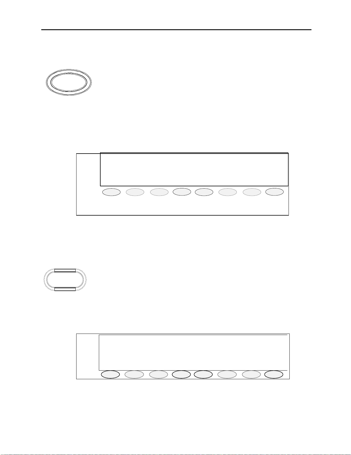
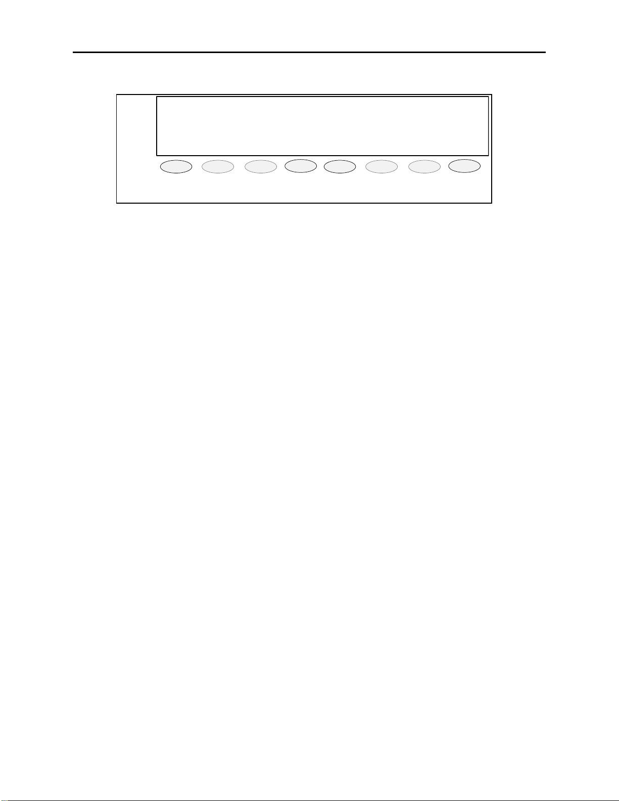
3.1.4 12/24 Hour Clock:
A user selectable 12/24 Hour clock will be displayed in the upper right corner of the display. See figure 1
Figure 1 Main Display View
3.1.5 Display Soft Program Keys 1-8:
Eight keys will be placed under the display. The function of the key will be listed on the bottom of the display and
change based on the current mode of operation as well as for setup purposes. These keys are not backlit.
3.1.6 Optional Handset:
When you come off hook the selected receive audio is transferred to the earpiece and the microphone mouthpiece
becomes active.
Page 9
Remote Control Console 3
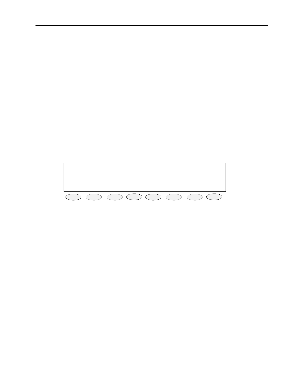
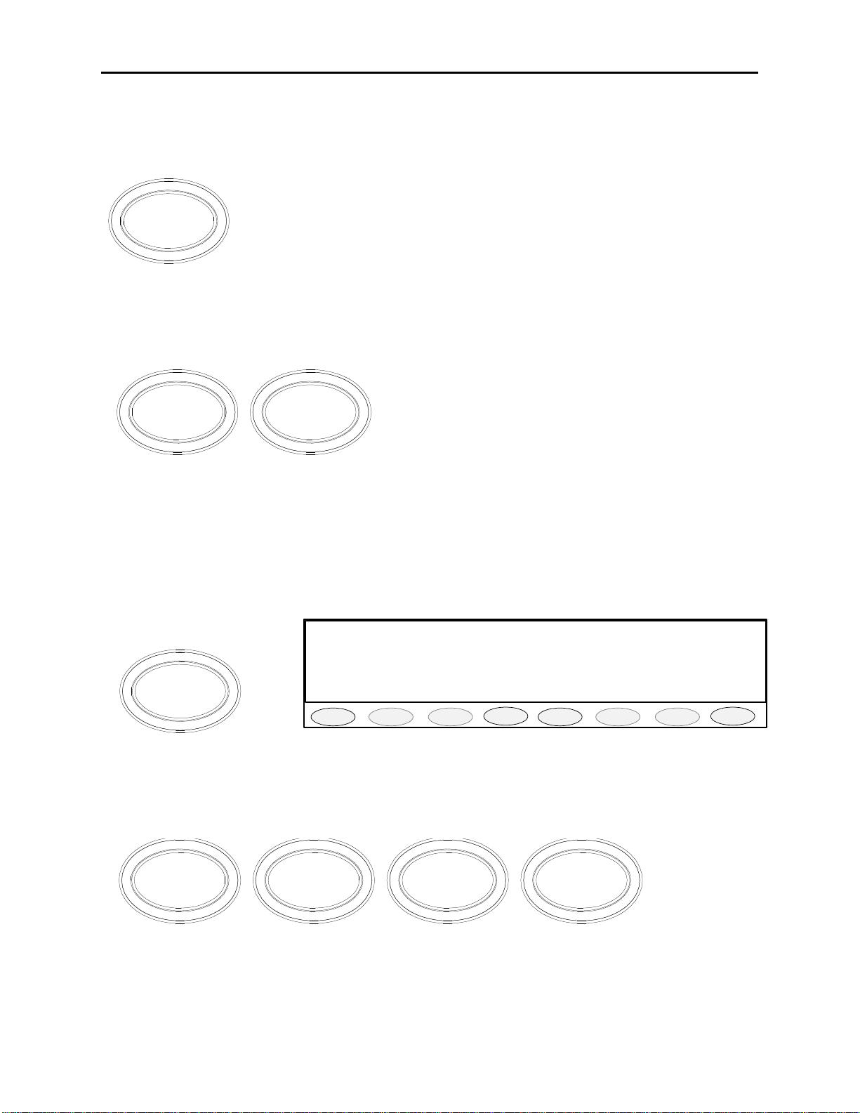
3.1.7 SELect Lines 1-8
The Select key selects the line for transmit operation or phone line selection. The select
keys function in a 1 of N manner. The GRP key must be toggled ON to select multiple lines
SEL
for simultaneous transmission.
3.1.8 RLS Lines 1-8
The Release key is used to unselect or release the line. This key is active only when the line
is currently selected or OFF-Hook. If the line is a phone line pressing release will generate
a flash-hook, hold down for 1 second and release to put phone ON-hook.
RLS
3.1.9 Line Activity Monitor (LAM) Indication
When RX audio is above the (settable) squelch threshold, a Blinking GREEN LED
indication under the RLS key for the line. The squelch threshold will be independently
settable for selected or unselected operation. The duration of the LAM indication will also
MUTE
be settable from 1-15 seconds.
3.1.10 Parallel TX Detect
Each line will have a parallel TX Detect that will cause the RLS GREEN LED to turn Solid
while the selected key tone is detected. In addition, it will be possible to mute the line if
TX is detected on it.
3.1.11 MUTE Lines 1-8
This mute is a single line only mute. When a line is not selected it is always in unselect
mode unless muted. MUTE will be backlit with YELLOW LED. The MUTE button will
have no effect on a Selected line. There is also the ability to set the level of mute as a setup
option.
3.1.12 VOL UP – VOL DOWN Lines 1-8
These two keys are used to control the volume of the audio present on the channel be it
select or unselect. These keys are not backlit.
InPTT
single line without having to reset the group setup. Phone line cards will light the LED if no phone line is connected
or the line is OFF-hook. This key is backlit with a RED LED.
3.1.13 InPTT Lines 1-8
Instant PTT is used to immediately key up the radio on that line only. All other selected
lines are ignored. This allows the console operator to be able to immediately respond on a
3.1.14 Basic Line/Function Tone Operation
The basic operating scenario would be a single line and function tone selected. Lines can be selected individually by
pressing any LN1-LN8 and function tone button F1-F16. Upon keying the microphone, a high level guard tone
followed the selected function tone is sent out, the low level guard tone is then transmitted along with the
microphone audio. Each Line/Function pair is unique and can have its’ own alphanumeric characters assigned to it
in the programming mode. The default characters have the LNx Fy label in the display with “x” the line number and
“y” the function number. Function Buttons can have either single or dual functions and is setup in the tech mode.
Page 10
4 Vega’s IP-1616
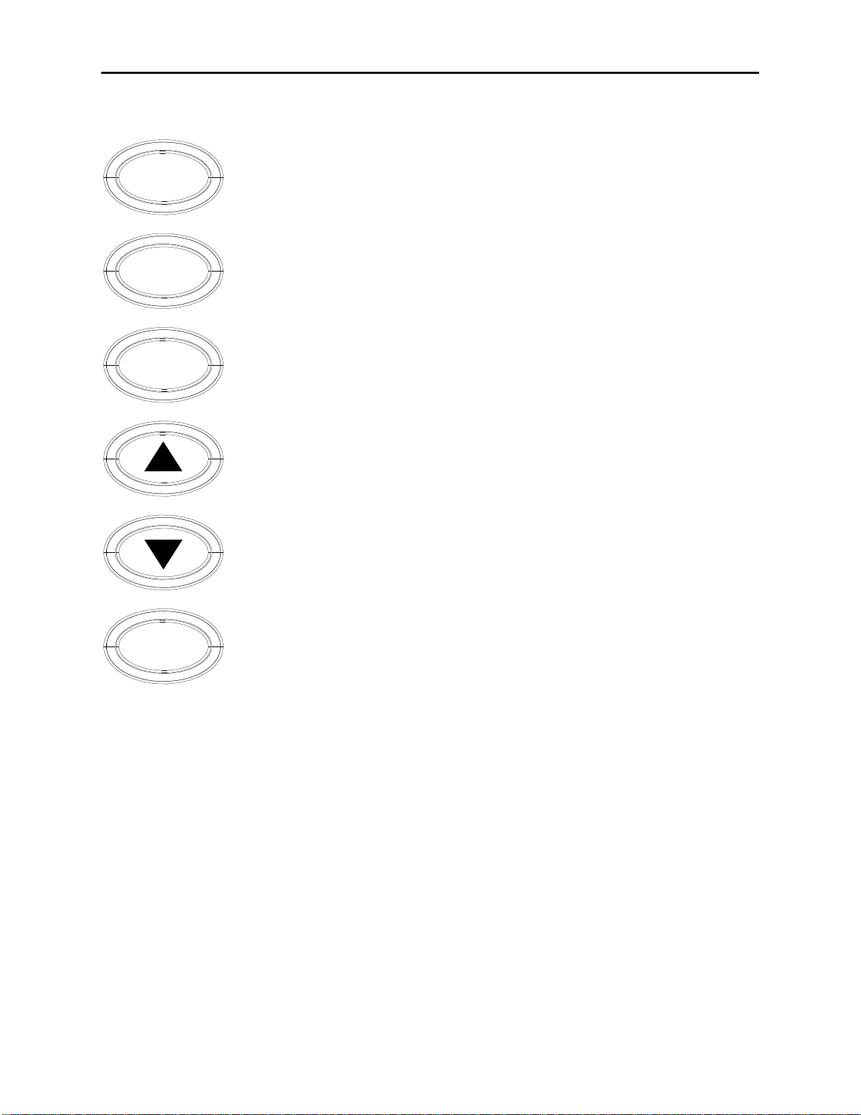
3.1.15 Function Tone Keys F1-F16
F1 F3 F5 F7 F9 F11 F13 F15
F2 F4 F6 F8 F10 F12 F14 F16
The function tone keys are used to select a function tone for a specific line. This function tone will be remembered
per line. If a group PTT is sent, the function tone that corresponds to each line will be sent on that line. If the
Function tone button is pressed independently, a Guard-Function burst is sent with no hold tone. Options will exist
to allow function tone keys to be programmed for disabled, levels, frequency, dual tone, and duration. These keys
are backlit with a single RED LED.
3.1.16 Intercom (IC) Button
When the IC button is pressed and held down the IP-1616 transmits audio without activating the tone generator.
Intercom is a PTT operation with the tone generator disabled. This is useful for communications between paralleled
consoles.
3.1.17 MON
MON
The MON key will send the monitor burst. The MON button should have the same programming options as the
function tone keys. This key is backlit with a single RED LED.
3.1.18 PTT
TRANSMIT
The PTT button will send the Guard-Function-Hold sequence on all Selected Channels
Page 11

Remote Control Console 5
3.2 Grouping Options
3.2.1 GRP and G1 Buttons
G1GRP
The GRP button is a press ON/OFF button that disables the 1of N functionality of the console. When the GRPSEL
button is selected it will illuminated and the operator can set up a Simul-group with as many tone lines desired. As
long as the button is illuminated the operator may add or delete lines in the group. The Green LED above each line
selection button denotes that the line is selected for transmission and reception. When the operator is finished setting
up the Simul-group the operator presses the GRP button again to revert back to the 1of N mode.
The G1 button allows for selection of a preprogrammed group. Within the tech mode, it is possible to set up
preprogrammed group. See Section 4.2 for operation of this feature.
3.2.2 TX ALL Button
TX ALL (Transmit All): This feature gives the user a convenient means of selecting all
lines for Simul-transmissions without having to group select one at a time.
To initiate Simulcast, momentarily touch the "TX ALL" on the keyboard. The line
TxALL
description will change to "TX ALL", and all available lines will automatically be
selected.
To disengage Simulcast, simply Select a single line in the usual manner, or press TX
again to revert to the previous setup.
3.2.3 RX ALL Button
RX ALL (Receive All): When pressed all lines are put into the unselect receive mode,
i.e. any line that is in the Mute mode will automatically be reset to unselect.
RxALL
Page 12
6 Vega’s IP-1616
♦ ♦ ♦ ♦ ♦ ♦ ♦ ♦ ♦ ♦ ♦ ♦
12:00AM
CROSS PATCH 1
BLOCK PTT
DRPALL
EXIT
PROG1
PROG2
PROG3
PROG4
PROG5
PROG6
PROG7
PROG8
3.3 Crosspatch Options
3.3.1 Crosspatch XP Button
X P
The XP key is LED backlit red to match the cross patch red select LED’s. Upon being pressed and released, the key
should illuminate solid, as do all the keys selected within the crosspatch. Any line that is in a crosspatch is lit red at
all times except when another crosspatch, to which it doesn’t belong, is selected. To add a line to the desired
crosspatch, press the associated lines SEL key. To drop it from the cross patch, press the RLS key.
The console operator cannot place calls that are in a current crosspatch into another crosspatch. If the operator
attempts to do so an error beep and message is placed onto the screen.
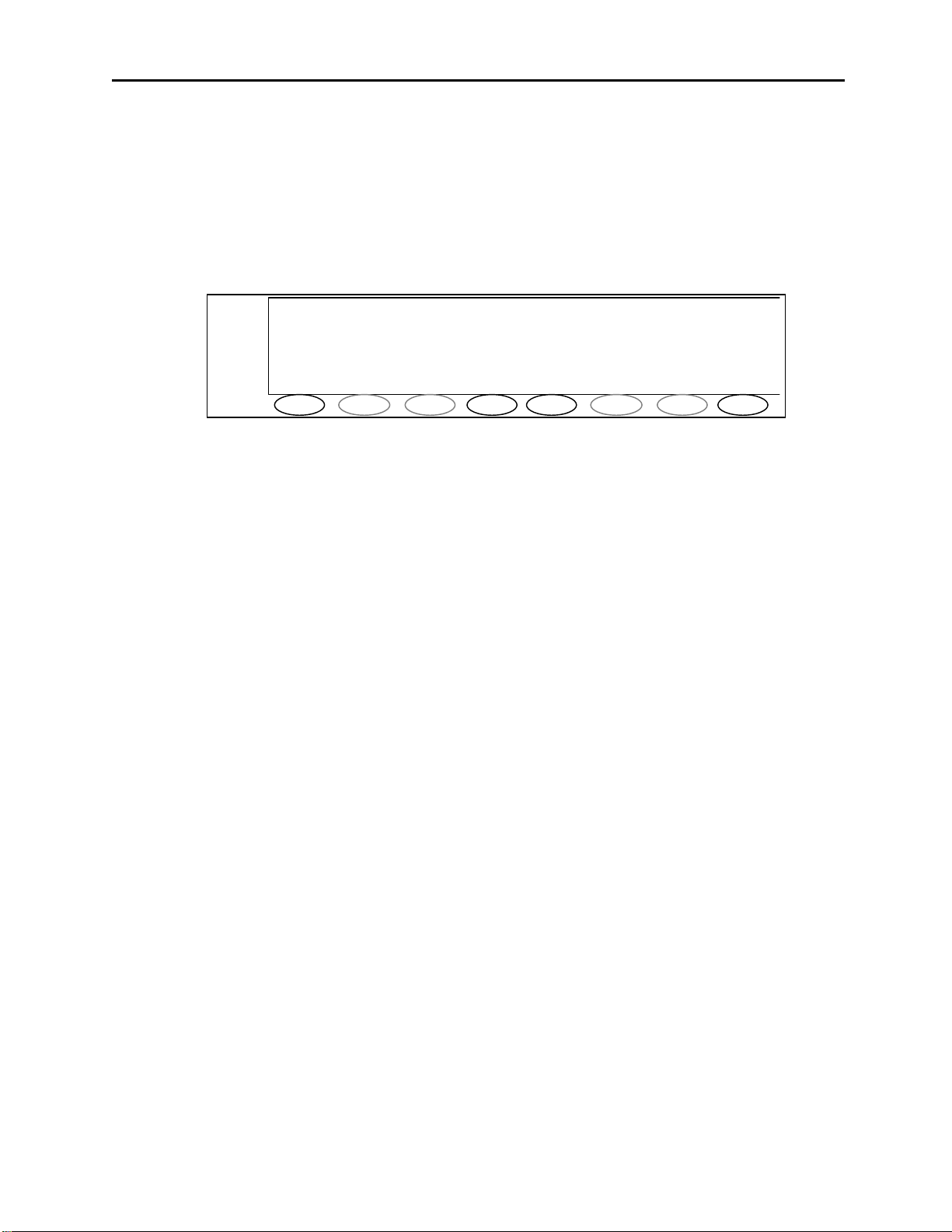
Figure 2 Cross Patch Display view
Figure 2 shows the view on the display when a crosspatch button is pressed; see Section 4.4 in this manual for
operation of crosspatch feature.
3.4 Paging Options
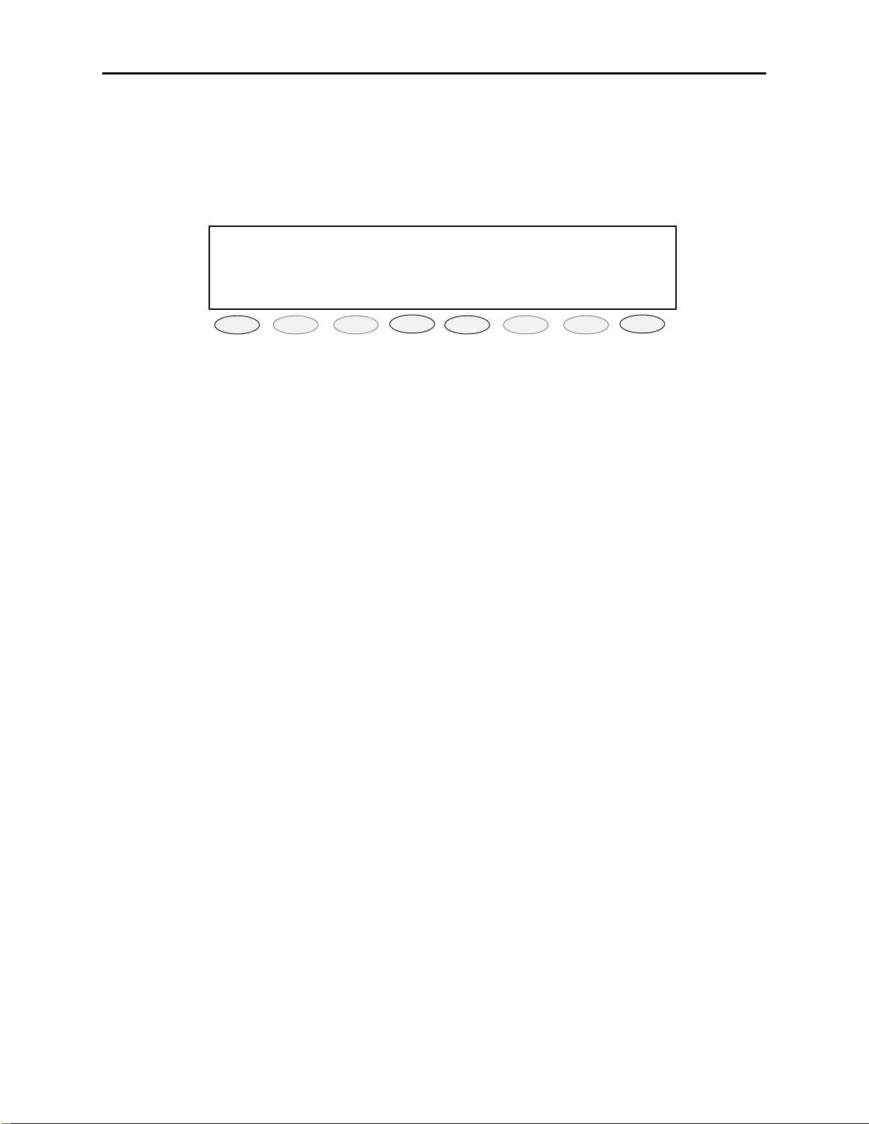
3.4.1 PAGE Button
The PAGE key will open the paging system on the display, see figure 3. The display and
PAGE
Upon pressing the page button, the top of the list of persons stored in the internal page table will be shown in the
display. The console operator can then scroll though that list, selecting the person/group to page. Each entry shall
have a number associated with it allowing direct entry of a page number to speed the page operation. See Section
4.5 for operation of the paging feature.
soft keys are then used to select the person/persons/groups that need to have a page sent to
them. The operator can then send the page or discard it. This key is backlit with a single
RED LED.
001:Siren On 12:00AM
>*002:Siren Off
003:Big Greg
LAST STACK UP DOWN SEND EXIT
PROG1
PROG2
PROG3
Figure 3 Paging Display view
PROG4
PROG5
PROG6
PROG7
PROG8
Page 13
Remote Control Console 7
Quick Page 12:00AM
B1 B2 B3 B4 B5 B6 B7 EXIT
PROG1
PROG2
PROG3
PROG4
PROG5
PROG6
PROG7
PROG8
3.5 Control Options
3.5.1 Supervisor Button
The SUP Button is used to disable all units on a particular line. Its connection is similar
to that of the crossmute function. Tech mode is utilized to determine which consoles will
have supervisory capability. It is possible to setup only specific consoles with this feature.
SUP
together. In addition the shield of the DB25 also needs to be connected together on all consoles, serving as a
common ground for all consoles. Assuming that console 1 has supervisory capability, when activated, Line 1 on
parallel consoles 2 and 3 would then be inhibited.
If a console has the feature enabled, by pressing the SUP Button, the Button will light and
disable all connected paralleled consoles. On the consoles that are being supervised, the
SUP Button will blink, if they have selected a line that the supervisor has selected. Pin 24
(line 1) and Pin 18 (line 2) of the DB25 line connector of all consoles are connected
3.5.2 AUX1 – AUX2 Buttons
A1 A2
These keys are used to close the auxiliary relays located on the back panel. Possible options include: Latch On/Off,
momentary, and timed. These keys are backlit with a single RED LED. . It can be disabled at setup time
Toggle Relay; gives the AUX button the ability to control the AUX RELAY output on the back panel. When
pressed, the Button will light and the relay will close. The next time the AUX button is pressed, the Button’s light
will turn off and the relay will open. The relay is rated to handle 500mA at 12VDC or 250mA at 115VAC.
Momentary Relay closes the relay for as long as the AUX button is pressed. The relay is rated to handle 500mA at
12VDC or 250mA at 115VAC.
3.5.3 B Menu Button
B1
The B menu button is used to update the display with 7 pre-programmed pages using the 8 soft keys below the
display. When pressed the display will show seven B and an exit key as shown above.
3.5.4 ALERT1-4 Buttons
ALERT 4ALERT 1 ALERT 2 ALERT 3
The ALERT 1-4 keys will be settable for one of the 5 possible Alert tone sequences. When pressed that alert tone
will be sent. If the line is not already keyed up, the line(s) will be key up and send the alert tone. The levels and
frequencies of the Alert tones will be programmable as well as the cadence. The five possible cadences will include:
Steady Tone, Hi-Lo Warble, Siren and Pulsed Steady Tone. These keys are backlit with a single RED LED.
Page 14
8 Vega’s IP-1616
♦ ♦ ♦ ♦ ♦ ♦ ♦ ♦ ♦ ♦ ♦ ♦
LINE 1/FREQ 1 12:00AM
Instant Recall Recorder:(UN)SELECT
Current Position:
-
SEL UNS
10 +10 PLAY STOP EXIT
PROG1
PROG2
PROG3
PROG4
PROG5
PROG6
PROG7
PROG8
3.5.5 MUTE Button
MUTE
The MUTE Button is used to mute unselect audio. It is programmable in tech mode to be a mute when pressed, or
mute for a programmable period of time. As long as MUTE is active, the Button will be lit up.
3.5.6 IRR-Internal Recall Recorder Button
IRR
20
-
Figure 4 IRR Display screen
The IRR button can be used to recall audio received in the last 4 minutes. The operator will be able to choose
whether this is Select or Unselect audio as well as the time frame from which to being or end playing. The initial
screen is shown in figure 4. See Section 4.6 for operation of the IRR feature.
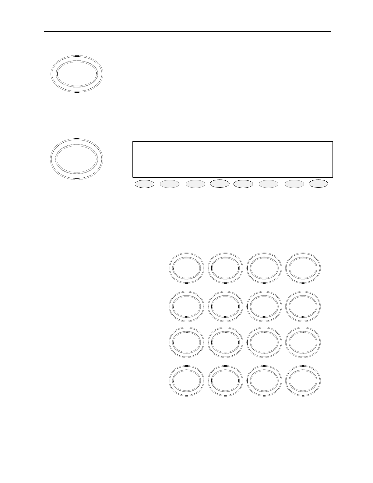
3.5.7 DTMF Keypad
The DTMF keypad is the standard 16 key
version. No backlighting is used for any of
the keys. The Alphabet characters are
included on the keys for alpha dialing. The
DTMF key being pressed/sent will sound
through the current speaker for feedback
purposes. The DTMF keys, when held, will
continue to sound their respective digit and
end upon release. If the IP-1616 is not keyed
when a DTMF key is pressed, the GuardFunction-Hold sequence will be sent before
the DTMF sound is placed onto the TX lines.
The DTMF keypad will just send the digit if
the unit is already transmitting. The keypad
should have programmable options to disable
it or to use it with no Guard-Function-Hold
sequence. The DTMF level should be
programmable. The DTMF hang time should
be programmable. The On-Off intervals
should also be programmable for sending
strings.
1 2 3
ABC DEF
4 5 6
GHI
JKL
7 8 9
PQRS
TUV WXYZ
*
MNO
#0
A
B
C
D
3.5.8 Per Line Squelch level control
Triggered from the LAM indications, if enabled receive audio is sent to speaker only when the LAM circuits are
active on a per channel basis.
Page 15

Remote Control Console 9
3.5.9 Parallel console update
The console will also run the standard function tone detector on all lines. This means that if it detects another
console keying up on a particular line, it will be able to detect the function tone being sent and change the local
function tone to the same number. This is so that parallel consoles can always stay on the same frequency across an
installation and gives the operator of the console an indication of what the last PTT command used as a frequency.
3.5.10 Pair Mode
There are four available wildcard groups. Function tones 1 and 2 are not allowed in a wildcard group and a function
tone may not be part of more than one group.
3.5.11 RX Block
The RX block function will allow the user to setup a number of other channels that should be RX muted during
transmit on this channel. As a setup item this requires that each channel have a list of up to 8 other channels that are
RX blocked. This results in a square 8x8 matrix. Consoles in the same room could be cross-muted for any blocked
channel, or they could RX block based on their own RX Block table and TX Detect input. The LED blinking the
mute button on the affected lines indicates RX Block.
3.5.12 TX Block
TX Block is defined as not allowing certain lines to both exist in the same group. If the operator tries to put TX
Blocked lines into a group the console will not allow it. Indications will be by audible feedback and a brief error
message on the display.
3.5.13 Dual F-Tone capable
The F1-F16 keys will be programmable such that they can send a defined Dual Function tone.
3.5.14 Incoming Select Call
A programmable incoming DTMF string will be setup per line. When the DTMF string is detected on a line, the
console will alarm (programmable) and the line will open the mute gate for the line for a programmable period of
time. When the timer ends, the line will go back to Mute condition, but the MUTE key will blink to indicate to the
user the line that the call came in on. The SEL key will continue to blink until a PTT operation is completed which
includes the line the DTMF string came in on. This function will also be capable of utilizing the radio ANI’s for this
function when implemented in IP223.
3.5.15 Microphone Connections
A desk microphone, gooseneck microphone may be installed for operation along with a handset (or headset) as
indicated on the rear of the IP-1616. When a PTT occurs from either of the two microphones, the other will mute so
as not to pick-up unnecessary ambient noise during transmission. Note that, in dual microphone configurations, the
desk microphone is the default microphone. The dedicated PTT button on the handset or headset must be pressed to
use the handset/headset.
3.6 Rear Panel Connections
3.6.1 +12 Power Connection:
The supplied inline power supplied is connected at J3.
3.6.2 Battery backup:
The Auxiliary power input J18 (3-Pin terminal block) is a diode-protected +12V input used for battery backup. Pin
(E) is also connected to the chassis allowing for positive grounding of the unit.
3.6.3 Handset/Headset connection:
Connection of handset or headset adaptor boxes (HB-2 or HB-3) is accomplished at this 4-pin modular jack.
Page 16

10 Vega’s IP-1616
3.6.4 Desk Microphone connection:
Connection of the MD-MS desk microphone is accomplished at this RJ-12 modular jack.
3.6.5 Auxiliary DB25 Connector:
Pin # Signal Pin # Signal
1. AUX Relay 1 Common 14. AUX Relay 1 N.C.
2. AUX Relay 1 N.O. 15. AUX Relay 2 Common
3. AUX Relay 2 N.C. 16. AUX Relay 2 N.O.
4. SPKRSEL - 17. SPKRSEL +
5. SPKRUNSEL - 18. SPKRUNSEL +
6. FTWS 19. N/C
7. N/C 20. N/C
8. N/C 21. N/C
9. N/C 22. N/C
10. N/C 23. Unselect Tape Out
11. Unselect Tape Out 24. Select Tape Out
12. Select Tape Out 25. AUX PTT
13. AUX Audio IN Shield/Shell = Ground
13 12 11 10 9 8 7 6 5 4 3 2 1
25 24 23 22 21 20 19 18 17 16 15 14
DB25
Connector
3.6.5.1 Auxiliary Audio Input:
The DB25 AUX connector provides AUX Audio Input and PTT. Pulling PTT to ground activates the Audio Input
line for transmitting. This input is a high impedance capacitance coupled input.
3.6.5.2 Auxiliary Speaker:
The DB25 AUX connector has Selected and Unselected audio outputs for driving external 8-ohm speakers.
3.6.5.3 Footswitch:
The DB25 AUX connector provides footswitch connection. This input acts as a console PTT when it is shorted to
ground.
3.6.5.4 Record Output
The DB25 AUX connector has Selected and Unselected audio via 600ohm transformer output for connection to a
voice-logging recorder.
3.6.5.5 Auxiliary Relay Output:
The DB25 AUX connector provides connection to the AUX relays, depending on the setting of the AUX button in
the tech mode, this output is a relay closure that can be used for whatever purpose is required.
3.6.6 Ethernet Port:
The Ethernet port connector supports a Tbase 10/100 CAT 5E connection.
Page 17
Remote Control Console 11
♦ ♦ ♦ ♦ ♦ ♦ ♦ ♦ ♦ ♦ ♦ ♦
LINE 1/FREQ 1 12:00AM
PROG1
PROG2
PROG3
PROG4
PROG5
PROG6
PROG7
PROG8
4 Operation
4.1 Radio Lines
4.1.1 Selecting:
When the desired line Select pushbutton is momentarily pressed, the receive audio from this Selected line is placed
on the speaker and the previously Selected line is disengaged. The currently Selected line name (programmable) is
displayed on the screen and the line Select indicator is illuminated.
The receive audio from the selected line will be heard on the consoles Select speaker and can be adjusted by the
selected master volume control, If the handset or headset is taken off hook, the receive audio is transferred to the
earpiece.
4.1.2 Changing Function Tones:
The function tone keys are used to select a function tone for a specific line. This function tone will be remembered
per line. If a group PTT is sent, the function tone that corresponds to each line will be sent on that line. If the
Function tone button is pressed independently, a Guard-Function burst is sent with no hold tone, these keys are
backlit with a single RED LED.
4.1.3 Muting Unselected Lines:
All 8 lines of receiver audio are played out the unselect speaker; undesired receiver audio may be muted by pressing
that lines MUTE button. The orange LED under the MUTE pushbutton will also illuminate to indicate a muted
condition.
The level of mute can be adjusted by the individual line volume controls, upon power-up, all lines will be Un-muted
until either engaging the Mute pushbutton, engaging the line Select pushbutton, or by a valid DTMF decode for each
line.
4.1.4 Releasing a Line:
To release a radio line, simply press the RLS pushbutton for that line.
4.1.5 Adjusting receive volume:
These two keys are used to control the volume of the audio present on the channel be it select or unselect. These
keys are not backlit.
4.1.6 Instant PTT:
To generate a PTT tone sequence whether the line is Selected or not, simply press the desired line’s instant PTT
pushbutton.
4.1.7 Supervisory Control Button:
The SUP Button is used to disable all units on a particular line, by pressing the SUP Button, the Button will light and
disable all connected paralleled consoles. On the consoles that are being supervised, the SUP Button will blink, if
they have selected a line that the supervisor has selected
4.1.8 Sending Alert Tones:
To send any of the alert tones down a selected line simply press the desired alert tone button.
Page 18

12 Vega’s IP-1616
4.1.9 RX ALL Button:
The RX ALL button is used as a global reset (clear) command for all active individual Mutes.
4.1.10 TX ALL Button:
The TX ALL button is used to select all lines for transmit with one button press.
4.1.11 Timed MUTE Button:
The timed MUTE button is used to mute all lines not in the Select condition, ideal when monitored lines need to be
silenced for a timed period to concentrate on selected call.
4.1.12 Intercom to parallel console:
To intercom to a parallel console simply select a shared line and press INTERCOM.
4.1.13 DTMF Decoder:
When a four digit DTMF code is sent from a mobile to the console, the code is decoded, the Select switch's Red
LED lights, and the console starts monitoring that line. The line will be monitored for 15 seconds. The call light will
stay on until the call is answered by the operator (base station Selected).
4.2 Group/SIMUL-Select operation
4.2.1 GRP Button
To manually select a group for transmit, simply press the GRP button (GRP LED on) and select any number of lines
via the desired SEL buttons. To release a line from the group simply press the desired lines RLS button while the
GRP button is illuminated. When the desired group is setup, simply toggle the GRP button (GRP LED off), when
the group is no longer required simply select another line and the group will clear.
4.2.2 G1 Button
This button is used when a predetermined group is known and used frequently, simply press the G1 button and the
predetermined group will be selected. If additional lines need to be added to the group, simply press the GRP button
(GRP LED on) and select any number of lines via the desired SEL buttons, when the group is no longer required
simply select another line and the group will clear.
Page 19
Remote Control Console 13
BLOCK PTT
DRPALL
EXIT
4.3 Crosspatch Operation
♦♦♦♦♦♦♦♦♦♦♦♦
CROSS PATCH X
12:00AM
PROG1 PROG2
The VOX detectors are used to determine which line has PTT control. Only one line can have PTT control within
the crosspatch at a time. All others are locked out until PTT control is relinquished or dropped. There is a
programmable hang timer on the PTT action from 50ms to 2000ms.
Another programming option is an inactivity timer and indication. The timer is set from the web browser interface
and goes off after the programmed interval when no activity has been detected within the patch. The programming
should include the option to automatically shutdown the patch or just notify the console operator of its timeout
expiration.
Softkey 1 is set for BLOCK. When pressed this key forcibly drops the current line that has control of the PTT
operation. The console will then wait for another line to take control of the crosspatch. This means that the line that
was just dropped, CANNOT take control until another line has done so first.
Softkey 2 is the console operator crosspatch PTT. When pressed, this button will light the PTT light and send
console audio to all channels within the selected crosspatch group.
Softkey 3 is the Drop all key. It Releases (RLS) all lines in the crosspatch, effectively stopping the patch.
Softkey 8 is the Exit key. When pressed the display will exit the cross patch mode, if a cross patch is left active, the
Red LED’s under the Crosspatch keys (C1-C3) blink as an indication of an active crosspatch.
PROG3 PROG4 PROG5 PROG6 PROG7 PROG8
Figure 5 Cross Patch Display view
4.3.1 Putting Lines into Crosspatch mode:
Select any of crosspatch select button (LED on), now select the desired lines and the RED LED will illuminate as
lines are selected. When finished selecting the crosspatch group, toggle the crosspatch select button again.
NOTE: Phone lines can only be added to crosspatch groups once the call is received or placed.
When multiple crosspatches are enabled, C1, C2 and C3 button LED’s will blink when there is an active patch
programmed into that location.
4.3.2 Blocking a line
At times it will be required to block a line from control of a crosspatch (noise on line, offending user, etc.), simply
select the desired crosspatch group and press the soft key labeled BLOCK (PROG1 soft key).
4.3.3 Talking on a crosspatch group:
To talk on a crosspatch group press display PTT (PROG2 soft key) and talk into the mic as normal. If multiple
crosspatches are enabled, select the desired C1, C2 and C3 button then press Crosspatch PTT (PROG2 soft key).
4.3.4 To disengage a crosspatch group:
To disengage a crosspatch group, simply select the desired crosspatch group and press display DRPALL (PROG3
soft key).
Page 20
14 Vega’s IP-1616
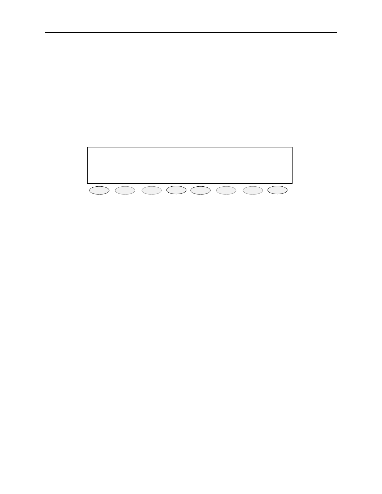
4.4 Paging
The PAGE key will open the paging system on the display. The display and soft keys are then used to select the
person/persons/groups that need to have a page sent to them. The operator can then send the page or discard it. This
key is backlit with a single RED LED.
Upon pressing the page button, the top of the list of persons stored in the internal page table will be shown in the
display. The console operator can then scroll though that list, selecting the person/group to page. Each entry shall
have a number associated with it allowing direct entry of a page number to speed the page operation.
001:Siren On 12:00AM
>*002:Siren Off
003:Big Greg
LAST STACK UP DOWN SEND EXIT
PROG1
The following softkey options shall be presented when the Page key is pressed.
LAST = recalls last page sent
STACK = Stacking, enter or select page, press (STACK) select next page and press
(STACK), when complete press (SEND)
UP = Scroll UP thru paging library
DOWN = Scroll DOWN thru paging library
SEND = send selected or last page
EXIT = Exit without sending page
PAGE = Start and Send button
DTMF keypad Digits
0-9 = Allows direct entry of a three digit number specifying a particular page.
A = UP button
B = Down button
C = Last Key button
D = Exit button
* = Stack
TRANSMIT (PTT) Button = Hold at end of page to add voice or press during page to stop
page.
DTMF Digits = Allows direct entry of a three digit number specifying a particular page.
The “>” symbol is placed in column 1 of the display to show the user where in the list they are pointing. When scroll
down is pressed and the “>” is at the bottom entry, the display scrolls down one position. The converse is true if the
“>” is at the top of the display. The “*” shows if a page has been selected for a send or stack operation.
PROG2
PROG3
PROG4
PROG5
PROG6
PROG7
PROG8
Page 21
Remote Control Console 15
♦ ♦ ♦ ♦ ♦ ♦ ♦ ♦ ♦ ♦ ♦ ♦
LINE 1/FREQ 1 12:00AM
Instant Recall Recorder:(UN)SELECT
Current Position:
-
20s
SEL UNS
10 +10 PLAY STOP EXIT
PROG1
PROG2
PROG3
PROG4
PROG5
PROG6
PROG7
PROG8
4.5 IRR-Internal Recall Recorder
The IRR button is used to recall audio received or transmitted during the last 4 minutes, the operator will be able to
choose whether this is Select or Unselect audio as well as the time frame from which to begin or end playing. Upon
pressing IRR button the display will show the current time position of 20 seconds, to increase the playback time
simply press softkey 3 (-10) for the desired time of playback then press PLAY. The initial screen is shown below.
-
SEL = Recalls Selected audio for playback
UNS = Recalls Unselected audio for playback
-10 = Step back in time frame
+10 = Step foreword in time frame
PLAY = Starts audio playback
STOP = Stops audio playback
EXIT = Exit to main display
Page 22

16 Vega’s IP-1616
CLK IP PIN EXIT
Edit A/P 12/24 back
5 Programming
5.1 Entering the Setup Mode
Setup of the IP-1616 is almost entirely done using a web browser. The first step required during setup is to assign
the Ethernet and Mask addresses to the IP-1616. This is done through the front panel. To enter the front panel setup
mode, press and hold MUTE-F16-GRP. The front panel display should look something like Figure 6. From the
front panel of the IP-1616, the internal clock, Ethernet parameters, and security PIN can be set.
IP:10.6.100.164 Mask:255.255.0.0
Programming Mode:
PROG1 PROG2 PROG3 PROG4 PROG5 PROG6 PROG7 PROG8
Figure 6 Initial Setup display screen
5.2 Setting the System Clock
Pressing PROG1 from the top-level setup menu will open the screen to set the internal Real Time Clock. Figure 7
shows the screen for the clock setup. PROG1 selects the Edit option that allows setting of the actual minutes and
hours. PROG2 sets AM or PM., PROG3 selects 12 or 24-hour mode, PROG4 returns to the previous setup screen in
Figure 6. The clock can also be directly setup by pressing MUTE-F16-C1. This key sequence bypasses the PIN
number and the main setup screen.
IP:10.6.100.164 Mask:255.255.0.0
Clock 11:16PM 12hr:
PROG1 PROG2
PROG3 PROG4 PROG5 PROG6
Figure 7 Clock setting display screen
PROG7 PROG8
5.3 Setting the PIN number
The Pin number is used to prevent unauthorized modification of operation parameters. When a PIN number is set,
the IP-1616 will prompt for it before allowing entry into the setup mode. The web-based setup for the IP-1616 also
has provision for a user password; it is the same four-digit value as the PIN number entered from this menu option.
Selecting PROG3 from the main menu will cause the IP-1616 to prompt for the new PIN number twice. If both are
entered identically, the new PIN number will take affect.
Page 23

Remote Control Console 17
IP Mask back
IP Mask back
Clr Del back
5.4 Setting the basic IP information
As was mentioned before, all other parameters are setup by using a browser such as Netscape or Internet Explorer.
Before connecting to the console with the browser, an IP address and Mask that is compatible with the users existing
network must be set. Figure 8 shows the screen selected when PROG2 is pressed from the main setup screen. See
your network administrator to determine the proper values. Figure 9 shows the dotted quad editing screen. Figure
10 shows the actual entry of the IP addresses. The following keys are used to enter the IP dotted quad once PROG1
or PROG2 is pressed.
IP:10.6.100.164 Mask:255.255.0.0
IP Setup [XXX.XXX.XXX.XXX]
PROG1 PROG2 PROG3 PROG4 PROG5 PROG6 PROG7 PROG8
Figure 8 IP Address setup screen
IP:10.6.100.164 Mask:255.255.0.0
IP Setup [XXX.XXX.XXX.XXX]
PROG1 PROG2 PROG3 PROG4 PROG5 PROG6 PROG7 PROG8
Figure 9 IP Address setup screen
IP:10.6.100.164 Mask:255.255.0.0
IP: 10.6.10X
PROG1 PROG2
DTMF 0-9: The DTMF digits allow entry of the specific numbers
DTMF A: DTMF digit A is the decimal point used in dotted quad
PROG4: The “back” key is pressed when the dotted quad has been entered
PROG1: The “Clr” function clears the current entered value and starts over
PROG2: The “Del” function deletes the last entered number
Once these values have been set, the unit must be reset for them to take affect. It is now possible to connect to
the IP-1616 with a computer and web browser.
PROG3 PROG4 PROG5 PROG6 PROG7 PROG8
Figure 10 IP Address setup screen
Page 24

18 Vega’s IP-1616
5.5 Entering IP-1616 Web Setup
To begin setup of the IP-1616 console, the user must know the base IP address that was entered from the front panel.
The address then entered into the browser is http://XXX.XXX.XXX.XXX, where the XXX’s refer to the values for
the assigned IP address. Upon pressing return in the browser the opening screen should appear as shown in Figure
11.
Figure 11 Initial WEB Browser screen
Clicking on the hyperlink [Click to Enter] will open a dialog box requesting user authentication. There is only one
user name defined. It is “admin”. If it is the first time the console as been started and no PIN number has been
entered, no password will be required. If a PIN has been set, enter it into the password field. Once the username and
password has been successfully entered, the opening web page for Basic Ethernet Setup will be displayed.
5.5.1 Orange Crossover Cable
An orange crossover cable provides for direct PC to IP-1616 programming through the Ethernet port. This cable
should not be used for a direct IP-1616 to Ethernet port connection.
Page 25

Remote Control Console 19
5.6 Basic Ethernet Setup
Figure 12 Basic Ethernet screen
The Basic Ethernet Setup screen is the default first screen when entering the setup mode, see Figure 12. Across the
top of the page is a table 4x3 cells in dimension. Each of these text strings is a link to a different setup page.
Clicking the mouse pointer on any of these will immediately load the page clicked on. Moving from one page to the
next does not automatically save any data that has been entered. To make changes to a page and save it to memory
requires that the “Submit” button at the bottom of each page be pressed. Submit has the effect of sending the
contents of the web page back to the IP-1616 for storage.
The fields of the Basic Ethernet Setup page are as follows:
5.6.1 Use DHCP Server:
The DHCP server check box is generally left unchecked. DHCP is the Dynamic Host Configuration Protocol. It
allows the IP-1616 to require all of the information for operation on the network bypassing its manual entry. Vega
does not recommend operating with DHCP on. It can cause the Base IP address to change unexpectedly making
changing setup of software more difficult. It can be useful for initial setup efforts in determining some of the other
parameters.
Page 26

20 Vega’s IP-1616
5.6.2 Unit IP Address:
The Unit IP Address is the base address assigned to the IP-1616. It must be unique on the Network. It identifies the
console for such operations as setup and software upgrades.
5.6.3 Subnet Mask:
The Subnet Mask is used by the IP Stack to determine what are local addresses and what address require use of the
gateway to be reached. See you network administrator for this value.
5.6.4 Gateway Address:
The Gateway address is the IP address for the node that is used to reach other networks. See your network
administrator for this value.
5.6.5 DNS Addresses 1-2:
The DNS Addresses, or Domain Name Service Addresses, are used to resolve word based IP addresses into dotted
quads. For example, www.espn.com requires lookup on a name server to determine the actual dotted quad IP
address. Currently word based addresses are not supported by the IP-1616. These addresses are stored as a place
holder to when they might be.
5.6.6 SNTP Address:
This is the IP address of the timer server on the network. The time server is used as a standard clock for all devices
on the network. It can be a PC, a national atomic clock source available on the internet, or a local GPS or atomic
clock based network resource.
5.6.7 SNPT Update Interval:
This is the amount of time between queries to the time server to update the clock. Since the real time clock of the IP1616 is already very accurate, this value only needs to be updated at most once per hour.
5.6.8 SNTP Local Time Offset:
A time server always gives its time as Greenwich Mean Time. Enter the value that corresponds to the consoles
location. See the table for a list of offset and enter the appropriate offset.
Location: Offset: Location: Offset:
Eniwetok, Kwajalien -12
-11
-10
-9
Pacific Time (US-Canada) -8
Mountain Time (US-Canada) -7
Central Time (US-Canada) -6
Eastern Time (US-Canada) -5
-4
-3
-2
-1
0
5.6.9 Packet Delay Before Playback:
The IP-1616 utilizes a 20ms UDP/IP packet to encode audio. Some buffering of these packets must occur before
playback to help absorb network jitter and delays, the typical value is 6. Larger values may be required for larger
networks, smaller values for simpler networks.
Page 27

Remote Control Console 21
5.6.10 QOS Bits:
The QOS bits section contains two entries. The first entry, QOS Precedence, is used when Differentiated Services
QOS is active on the network. Typically this value is left at 0 for normal traffic and 5 for voice traffic. The second
entry, D, T and R bits, are used for advanced purposes. These bits are usually 0. Contact your Information Services
department for proper values for these entries.
5.6.11 Local IP Addresses:
Up to 10 addresses can be entered for the Local IP addresses. These addresses should correspond to the base IP
address of the other IP-1616 consoles within the same room. This list is used for the Ethernet crosspatch function.
The IP-1616 examines the source of the audio and flags it if the source was from another console in this list.
Page 28

22 Vega’s IP-1616
5.7 Multicast Setup
Figure 13 Multicast Port setup screen
Figure 13 shows the Multicast Setup screen is used to determine which ports the IP-1616 will use to communicate
various channel information on. The specific columns are discussed next:
5.7.1 Enable via Ethernet:
This checkbox is used to turn Ethernet connectivity on and off. If this box is unchecked, audio received from the
analog connections of the IP-1616 will not be echoed to the Ethernet. In addition, Ethernet traffic will not be mixed
into the audio of the IP-1616.
5.7.2 Multicast Address:
The Multicast Address is used as the broadcast address for all audio traffic. This number must be between 224.0.0.2
and 239.255.255.255. All lines that are to interoperate must have the same Multicast Address.
5.7.3 RX and TX Ports:
The next two columns specify the port number for each channel. This number must be unique, per channel, and be
greater than 1024. As an example, consider Line 1 above in. The RX Port is 1054 and the TX Port is 1072. All
consoles that wish to monitor receive audio for channel 1 must have their Base Multicast address set the same as well
as the same RX Port number. The same goes for TX audio. Any console on the network that wishes to transmit
must set its port number to 1072.
5.7.4 Channel Hops:
The Channel Hops value represents the number of routers the multicast audio packets will go through before being
stopped. Network design will dictate this value. If audio is not reaching a particular node on the network, increasing
this value is one option that might be tried.
Page 29

Remote Control Console 23
5.8 Per Line Setup Parameters
Figure 14 TCRD Setup screen
Figure 14 shows the TCRD Line setup screen. Each lines setup parameters can be viewed and changed by pressing
the buttons numbered 1-8. Note that pressing those buttons does not save the current information on the screen. The
user must first Submit the information to be saved and then click on a button to move to the next lines information.
All of the information on this web page is specific to the line. Descriptions of the various parameters follow.
5.8.1.1 Line Enabled:
The Line Enabled checkbox at the top middle enables or disables the line. If the Line is disabled, it will not allow
selection for transmission or play received audio.
Page 30

24 Vega’s IP-1616
5.8.1.2 Select Call String:
The Select Call string is used to allow a user in the field to guarantee that the dispatcher is monitor in the channel.
The String is a sequence of DTMF digits that when received, will open the MUTE gate and allow receive audio
through to the speakers.
5.8.1.3 Select Call Open Time:
When the Select Call String is received, this value is the amount of time that the mute gate remains open for the
received audio. After the timer has expired and indication continues to notify the console operator which channel the
received audio came in on. It will continue until the operator presses performs a PTT operation on the channel.
5.8.1.4 Disable Mute:
By check this box, the console will not allow the line to be muted. This forces the console operator to monitor the
line.
5.8.1.5 Min Mute Level:
The Mute key can be set to be a audio level reduction rather than an on/off function. By setting this entry to –20 for
example, when the mute is activated for this line, the audio will be reduced by –20dB rather than all the wa y off. A
value of 0, has the effect of a hard mute.
5.8.1.6 TX Enabled:
Checking this box allows the line to be selected for TX operations. Leaving it unchecked allows the operator to still
monitor the channel.
5.8.1.7 InPTT Enable:
When checked, the InPTT button is allowed to function.
5.8.1.8 Duplex Enable:
Checking this box will make the line Full duplex.
5.8.1.9 F-Tone 1-16 Enable:
Checking this box will allow the associated Function tone to be selected.
5.8.1.10 Ftone1-16 Alphanumeric:
This text string will be displayed when the particular line and function tone is selected.
5.8.1.11 RX Block:
The RX block checkboxes allow the user to select other channels that should be RX muted during transmit on this
channel.
5.8.1.12 TX Block:
The TX Block checkboxes prevent checked boxes from being selected at the same time as this channel. The IP-1616
will automatically reciprocate selections between two different lines.
5.8.1.13 Pairs/Wildcard:
There are four available wildcard groups. Function tones 1 and 2 are not allowed in a wildcard group and a function
tone may not be part of more than one group. One function tone from each group can be active at a time, plus either
F1 or F2. This allows for function tones to have control functions, but that are not used for actual frequency control
of the radio.
Page 31

Remote Control Console 25
5.9 General Gain Setup
Figure 15 General setup screen
The General Gain Setup web page is shown in Figure 15. The IP-1616 is based largely on software controlled
variable resistors with a resolution of 1.5dB per step. Each output is set to be at is maximum drive and may therefore
need to have its output reduced to get the proper level out/in. The General gain screen allows the operator to adjust
the levels down as required. As an example, if given the particular properties of a transmission line, it is determined
that the output level is 3dB to high, the corresponding Transmit Gain would be set to –3.0dB. The actual values
adjusted are spelled out on the web page and should be adjusted as required.
Page 32

26 Vega’s IP-1616
5.10 Global System Setup
Figure 16 Global setup screen
Figure 16 shows the setup screen for all the functions that are not line specific. Each of the options on this page are
discussed in the following sections.
Page 33

Remote Control Console 27
5.10.1 Supervisor Enable:
When checked, the SUP button will be active on the console. This allows a console operator to take control of any
selected line. It will pull the SUP pin low such that parallel connected consoles (both analog and Ethernet) will not
be able to transmit or monitor receive audio on the line. The SUP input is active at all times no matter the status of
this checkbox.
5.10.2 Supervisor Timeout:
This variable sets a timeout for the supervisory button. Setting the value to a 0 make it a toggle on/off function.
Setting the value to a number makes it a timed supervisory.
5.10.3 TX All Key Enable:
This check enables and disables the TX All button on the front panel.
5.10.4 TX Delay:
This value is the delay in ms for microphone audio. By setting this value to something greater than the system setup
time, the console operator can begin speaking after the PTT is pressed and the audio will be delayed until the system
is actually able to transmit.
5.10.5 Auto Monitor Enable:
This checkbox is used with the handset/headset option. When the handset/headset is taken offhook, the monitor
burst is sent.
5.10.6 CRP Timeout:
The time in seconds allowed for inactivity before a crosspatch will be automatically dropped.
5.10.7 Mute UNSEL w/ PTT:
This option will mute the receive audio from any channel that is not selected during a PTT operation.
5.10.8 Master Mute:
The Master Mute button of the console mutes all unselected audio. Setting the value to a 0 make it a toggle on/off
function. Setting the value to a number makes it a timed mute. The “mom” checkbox sets it as a momentary
function.
5.10.9 SEL Tape Output Mix:
Each of these checkboxes determines what kind of audio is summed into the SEL tape output. The SEL tape output
can be any combination of select, unselect, and crosspatch audio.
5.10.10 SEL Tape with Volume:
When checked, only speaker audio will be sent to the tape out, no muted lines or microphone audio is included.
5.10.11 Handset or Headset RX routing:
When a handset or headset is installed, this box should be checked so that the IP-1616 knows where to route receive
audio based on hookswitch position.
5.10.12 Summed RX to Handset or Headset:
When checked, provides both Select and Unselected RX audio to the earpiece.
5.10.13 Panel PTT Default Mic:
This pull down menu allows a technician to select which microphone input will be sourced on a master PTT or
InPTT press. It must be set to Gooseneck if the gooseneck mic is being used. The Handset and Deskmic inputs will
still operate on their own integral PTTs. Setting it to Deskmic will activate the Deskmic input when the front panel
PTT (or InPTT) is pressed, and Handset will activate the Handset port similarly.
Page 34

28 Vega’s IP-1616
5.10.14 DTMF Keypad Enable:
Allows the DTMF keys to be enabled or ignored.
5.10.15 DTMF Flywheel:
The DTMF flywheel sets the time in milliseconds between key presses without the unit de-keying.
5.10.16 DTMF On Time:
The minimum duration of DTMF digit.
5.10.17 DTMF Off Time:
The minimum time between DTMF digits.
5.10.18 DTMF Phone Level:
The approximate absolute level of the DTMF digits for the phone lines.
5.10.19 DTMF Line Level:
The approximate absolute level of the DTMF digits for radio lines.
5.10.20 DTMF Sidetone:
When checked, provides DTMF sidetone to be played on the Select speaker.
5.10.21 DTMF Sidetone Level:
The approximate relative level of the DTMF sidetone played on the Select speaker.
5.10.22 Group G1 Setups:
The predefined group keys are setup in this section of the web page. By checking SEL and MUTE check boxes, a
predefined console configuration can be set. Once defined, the operator can press the associated group key and the
IP-1616 will immediately change to that configuration. The text string for each group is displayed when the group
key is pressed.
5.10.23 Aux Relay Button Setups:
The two Aux relay buttons (A1-A2) are setup in this section of the Global Setup page. Each button can be
programmed to be deactivated, toggle, and timed. In addition, and independently per button, the relay can be
programmed to close on a PTT operation.
5.10.24 Alert Tone Buttons Setup:
The four Alert Tone buttons can be setup to generate different tones. They can be made active or inactive. Single
Tone, Pulsed Tone, and Hi-Lo warble are all supported. The Single Tone and Pulsed Tone use the Low Freq setting
only. An approximate relative level is also supported for each Alert Tone.
5.10.25 B Menu Button Setup:
Page 35

Remote Control Console 29
5.11 Paging Setup
Upon selecting the Paging Setup
link, the web page shown in
Figure 17 will be displayed. This
page is typically the first location
for setup of the paging system of
the IP-1616 console. The IP-1616
will allow setup of up to 10
simultaneous paging encoder
types. The three currently
supported paging encoders are:
Quickcall II 100 and 1000 group,
as well as DTMF. To setup each
of the 10 encoders, use the pull
down box in the Page Type
column to select the type of
encoder. Once an encoder has
been selected, clicking on the
setup button on the same row will
open the associated setup screen
for the encoder. The setup screens
for each appear next.
5.11.1 2 Tone 100 Setup:
The setup screen in Figure 18 is for 2 Tone 100. This is
the setup screen that appears when the Setup button is
pressed from the Paging setup screen and 2 Tone 100 is
selected in the pull down menu. This format requires
only a two-digit code to generate a paging sequence.
Going from top to bottom, the parameters are as
follows:
The top two lines give information as to the type of
encoder being setup, as well as which entry in the table
of 10 is being setup/modified.
5.11.1.1 Name for Paging Setup:
This is a character string that associates a name with the
particular setup for this encoder. The name will be
displayed as an option in the Paging Directory screen.
5.11.1.2 Delay before first Tone:
This option is the amount of time allowed from PTT
until the first tone is played
Figure 17 Paging setup screen
5.11.1.3 Tone #1 and #2 Group Numbers:
The Tone Group numbers are selected from the top row
of Table 1 and Table 2. These are the standard tables for Two-Tone Signaling.
Figure 18 2-Tone 100 paging setup screen
Page 36

30 Vega’s IP-1616
Vega Group No.
Tone Groups
0
1
2
3
4
5
6
7
8
9
Diagonal
Vega Group No.
1
Mot 1
330.5 569.1
349.0 600.9
368.5 634.5
389.0 669.9
410.8 707.3
433.7 746.8
457.9 788.5
483.5 832.5
510.5 879.0
539.0 928.1
569.1 979.9
8
Mot 2
2
9
3
Mot 3
1092.4 321.7
288.5 339.6
296.5 358.6
304.7 378.6
313.0 399.8
953.7 422.1
979.9 445.7
1006.9 470.5
1034.7 496.8
1063.2 524.6
569.1 569.1
Table 1
10
4
Mot 4
11
5
Mot 5
553.9 122.5 358.9
584.8 1153.4 398.1
617.4 1185.2 441.6
651.9 1217.8 489.8
688.3 1251.4 543.3
726.8 1285.8 602.6
767.4 1321.2 668.3
810.2 1357.6 741.3
855.5 1395.0 822.2
903.2 1433.4 912.0
979.9 979.9 979.9
12
6
Mot 6
13
Mot A
7
14
Tone Groups
0
1
2
3
4
5
6
7
8
9
Diagonal
Entering a number from 1 to 14 in each of these fields will then select, based on the two digit pager code, which two
frequencies will be played in succession.
Mot B
371.5 346.7
412.1 384.6
457.1 426.6
507.0 473.2
562.3 524.8
623.7 582.1
691.8 645.7
767.4 716.1
851.1 794.3
944.1 881.0
979.9 979.9
Mot Z
GE A’
682.5 652.5 667.5 1472.9 1930.2
592.5 607.5 712.5 1513.5 1989.0
757.5 787.5 772.5 1555.2 2043.8
802.5 832.5 817.5 1598.0 2094.5
847.5 877.5 862.5 1642.0 2155.6
892.5 922.5 907.5 1687.2 2212.2
937.5 967.5 952.5 1733.7 2271.7
547.5 517.5 532.5 1781.5 2334.6
727.5 562.5 577.5 1830.5 2401.0
637.5 697.5 622.5 1881.0 2468.2
742.5 742.5 742.5 None None
Table 2
GE B’
GE C’
Mot 10
Mot 11
5.11.1.4 Tone #1 Duration:
The duration in milliseconds the first tone will be played.
Page 37

Remote Control Console 31
5.11.1.5 Gap Duration:
The duration in milliseconds between tones.
5.11.1.6 Tone #2 Duration:
The duration in milliseconds the second tone will be played.
5.11.1.7 Group Tone Duration:
Each of these durations is set in milliseconds and generally conform to the standard paging plans listed in Table 3:
Tone #1 (ms) Gap (ms) Tone #2 (ms) Group Call (ms) Type
1000 - 3000 8000 GE std, Mot std Tone and
Voice
400 0 800 8000 Mot. Tone Only
1000 0 3000 6000 NEC-B
1000 300 3000 6000 NEC-A
1000 0 1000 4000 NEC-C
400 0 800 4000 NEC-M
500 0 500 3000 NEC-L
400 0 400 3000 NEC-D
Table 3
5.11.1.8 Enable Diagonal Tone:
This checkbox determines if the diagonal tone of a group is used or not. When the diagonal tone is disabled, the next
two entries are ignored and the second tone is played for the diagonal tone duration period. When the diagonal is
enabled, the diagonal tone (Diagonal Tone Frequency) is used in place of either the first or second tone depending
on the final check box (Diagonal Tone Location). Anytime both the first and second tones come from the same
tone group, group call paging is supported.
5.11.2 2 Tone 1000 Setup:
The 1000 group paging mode is similar to the 100 group paging
group except that it adds an additional number making it a three
digit code. The new first digit is used for an additional table
lookup, which then points to two of the columns in Table 1 and
Table 2, listed previously in the 100 group setup. Figure 17
shows the entries required for setting up one of the 1000
encoders.
5.11.2.1 Name for Paging Setup:
A 10 digit name associated with this particular paging setup.
5.11.2.2 Delay before first Tone:
This option is the amount of time allowed from PTT until the
first tone is played
5.11.2.3 Tone Plan Number:
The tone plan number is selected from the list of tone plans in
Table 4, Table 5, and Table 6. If the pager to be reached is
N349, the Tone Plan Number would be set to 12 which
Page 38

32 Vega’s IP-1616
corresponds to group N. All pagers using the N group would then reference this encoder setup in the listing of all
persons. The 3 corresponds to which line in group N to select the tone groups from. In this case, 3 says to take both
the first and second tone from group number 3 (3+3). So, for N349, the first tone sent would be 313.0 for 1 second,
followed by 1063.2 for 3 seconds.
Vega Codeplan #
Pager Capcodes
0xx
1xx
2xx
3xx
4xx
5xx
6xx
7xx
8xx
9xx
Vega Codeplan #
Pager Capcodes
1
Mot B 2 Mot C 3 Mot D 4 Mot E 5 Mot F 6 Mot G 7 Mot H 8 Mot J 9 Mot K
2+4 N/A N/A N/A N/A N/A N/A N/A N/A
1+1 1+1 1+1 1+1 1+1 1+1 1+1 1+1 1+1
2+2 2+2 2+2 2+2 1+3 1+3 1+3 1+4 1+4
3+3 1+2 1+2 1+2 3+3 3+3 3+3 4+1 4+1
1+2 4+4 1+5 2+1 4+4 3+1 3+1 4+4 4+4
1+3 1+4 5+5 1+6 3+1 5+5 1+6 5+5 1+6
2+1 2+1 2+1 6+6 1+4 1+5 6+6 1+5 6+6
3+1 4+1 5+1 6+1 4+1 5+1 6+1 4+5 6+1
2+3 2+4 2+5 2+6 3+4 3+5 3+6 5+4 4+6
3+2 4+2 5+2 6+2 4+3 5+3 6+3 5+1 6+4
Table 4
10
Mot L
11
Mot M
12
Mot N
13
Mot P
14
Mot Q
15
Mot R
16
Mot S
17
Mot T
0xx
1xx
2xx
3xx
4xx
5xx
6xx
7xx
8xx
9xx
N/A 4+2 4+2 4+2 4+2 4+2 4+2 4+2
1+1 2+3 2+3 2+3 2+4 2+4 2+5 3+4
1+5 2+2 2+2 2+2 2+2 2+2 2+2 4+3
5+1 3+3 3+3 3+3 4+2 4+2 5+2 3+3
1+6 4+4 3+2 3+2 4+4 4+4 2+6 4+4
5+5 3+2 5+5 2+6 5+5 2+6 5+5 5+5
6+6 2+4 2+5 6+6 2+5 6+6 6+6 3+5
6+1 4+2 5+2 6+2 4+5 6+2 6+2 4+5
5+6 3+4 3+5 3+6 5+4 4+6 5+6 5+4
6+5 4+3 5+3 6+3 5+2 6+4 6+5 5+3
Table 5
Page 39

Remote Control Console 33
Vega Codeplan #
Pager Capcodes
0xx
1xx
2xx
3xx
4xx
5xx
6xx
7xx
8xx
9xx
18
Mot U
4+2 4+2 4+2 N/A 4+2 10+10 11+11 10+10
3+4 3+5 4+6 7+7 1+1 11+10 12+11 12+10
4+3 5+3 6+4 8+8 2+2 11+11 12+12 12+12
3+3 3+3 5+6 9+9 1+2 10+11 11+12 10+12
4+4 3+6 4+4 7+8 4+4 12+12 N/A N/A
3+6 5+5 5+5 7+9 5+5 12+10 N/A N/A
6+6 6+6 6+6 8+7 2+1 12+11 N/A N/A
6+3 6+3 4+5 9+7 4+5 10+12 N/A N/A
4+6 5+6 5+4 8+9 5+4 11+12 N/A N/A
6+4 6+5 6+5 9+8 2+4 N/A N/A N/A
19
Mot V
20
Mot W
Mot Y
5.11.2.4 Tone #1 Duration:
The duration in milliseconds the first tone will be played.
21
Table 6
22
Mot
MT
23
GE X
24
GE Y
25
GE Z*
5.11.2.5 Gap Duration:
The duration in milliseconds between tones.
5.11.2.6 Tone #2 Duration:
The duration in milliseconds the second tone will be played.
5.11.2.7 Group Tone Duration:
The duration in milliseconds the group tone will be played.
5.11.2.8 Enable Diagonal Tone:
This checkbox determines if the diagonal tone of a group is used or not. When the diagonal tone is disabled, the next
two entries are ignored and the second tone is played for the diagonal tone duration period. When the diagonal is
enabled, the diagonal tone (Diagonal Tone Frequency) is used in place of either the first or second tone depending
on the final check box (Diagonal Tone Location). Anytime both the first and second tones come from the same
tone group, group call paging is supported.
5.11.2.9 Diagonal Tone Location:
These are the same entries as the previous section in Table 3.
Page 40

34 Vega’s IP-1616
5.11.3 DTMF Paging:
DTMF paging is also supported in the IP-1616 console. The
standard DTMF digits are allowed in any length. Figure 20
shows the web setup required for enabling DTMF paging.
The entries are similar to those before.
5.11.3.1 Name for Paging Setup:
A 10 digit name associated with this particular paging setup.
5.11.3.2 Delay before first Tone:
This option is the amount of time allowed from PTT until the
first tone is played
5.11.3.3 Digit On Time:
The amount of time the DTMF digit is played.
5.11.3.4 Digit Off Time:
The amount of time spacing between DTMF digits.
Figure 20 DTMF Paging screen
5.11.3.5 Total Page Digits:
The number of digits in a standard page. All pages that utilize this option will expect this number of digits.
5.11.4 Manual Paging:
Manual paging is supported in the IP-1616 console; this
provides the ability to create a tone page using tones not
included within the tone charts. See Figure 22.
5.11.4.1 Name for Paging Setup:
A 10-digit name associated with this particular paging setup.
5.11.4.2 Delay before first Tone:
This option is the amount of time allowed from PTT until the
first tone is played
5.11.4.3 Gap Duration:
The duration in milliseconds between tones.
Figure 21 Manual Paging screen
Page 41

Remote Control Console 35
5.12 Page Table Entries:
Figure 22 Paging Directory screen
The previous section on Paging Setup allowed definition of the various encoders to whatever encoder scheme was
required. The second setup step required involves entering the individual page codes on a per user basis. Entry into
this table will be through a browser and web pages hosted by the IP-1616 console. The screen can be seen in Figure
22.
The first column is the entry number. Up to 100 separate entries can be maintained in the system at any one time.
Only 20 can be on screen at one time for editing. The second column is the name of the person or action that can be
used by a console operator to identify the page. As can be seen in Entry 3, the drop down list will consist of all
enabled paging encoders plus a stack option. The next two columns are the Line and Freq for the page to go out on.
The Talk Time column is used to allow the dispatcher time to speak after the page tones have been completed. The
unit will stay PTTed for this amount of time after the page and then dekey. The operator has the option of pressing
the PTT key during this time to extend their talk time. The final column is the page string. It consists of the digits
necessary to send the page.
Page 42

36 Vega’s IP-1616
When a manual page format is selected, the Page String block must be entered as follows: FFFF;TTTT;FFFF;TTTT
where FFFF equals frequency in Hz and TTTT equals time in milliseconds. Using Figure 22 as an example, entry #7
is a manual page to a TV station copter, the first tone is 1000Hz for 500ms and the second tone is 2000Hz for
500ms.
When the stack option is selected for the Page Format, the Line and Freq have no effect. In this mode, the Page
String becomes a semi-colon delimited list of page numbers to send (1;2;3). Each of these pages will go out on their
respective lines (and remain keyed while the other pages are going out). The operator is then given a go-ahead
beep/message to indicate that the pages are complete and the voice portion of the message can be sent. The PTT
button will extend this time as in the other modes. All lines that were part of the stacked page are selected for this
voice message. When the console dekeys, it will revert back to the original SEL/UNSEL configuration.
5.13 Clone From Other Console
Figure 23 Cloning screen
The Clone from Other Console screen is show in Figure 23. It works similarly to the other Vega products clone
features. In this case, both consoles must be connected to the Ethernet network. Enter the dotted quad of the console
to clone from and pressing the Submit button will copy the entire configuration from the other console. The only
things not copied from the other console are the serial number, Base IP address, and Mask IP address. After copying
the values, they still must be saved to EEPROM memory for permanent storage.
Page 43

Remote Control Console 37
5.14 PIN Change
Figure 24 PIN number change screen
The PIN change web page is used to set the “admin” password for the console and is shown in Figure 24. Enter the
four-digit number in both entry boxes and click Submit. If the two PIN’s are the same, the PIN number will be
updated in memory. To take effect, it must be saved to EEPROM memory and a reboot must occur. The PIN will
be immediately effective in the DSP setup screen mode however.
5.15 Save to EEPROM
Figure 25 Load/Save screen
Figure 25 shows the screen for saving parame ters to non-volatile memory. Three buttons are available. The first is
to Reset Parameters back to factory defaults. This will clear everything out of memory. It does not save these values
however. Clicking the Save Current Parameters button will store all parameters in memory to Non-Volatile memory
for permanent storage. It will also reset the DSP so that it may reload its configuration data in a controlled manner.
The third button is for remote reset of the IP-1616, this will allow you to cycle power on a remote unit.
Page 44

38 Vega’s IP-1616
5.16 Reprogramming the IP-1616 Software
1) The file you downloaded from the vega-signaling.com website includes two files. One is the directions you are
currently reading, and the second is ftpdl.exe. The ftpdl.exe file is the program that is used to update the software,
via the Ethernet port, of the Vega VoIP products. In addition you must download a copy of the software for the
product you wish to update.
Figure 26 FTP Reprogramming Screen
2) Copy all files into a subdirectory. Create a shortcut to the ftpdl.exe program file.
3) Run the program ftpdl.exe. Figure 26 above shows the screen as it appears at runtime.
4) Enter the IP address of the device to update. Figure 26 shows the IP-1616 console default of 10.6.100.216
5) Enter the User name and password fields into the FTP dialog box. Figure 26 shows “admin” as the username,
with no password.
6) Select the file name to download. In this case, IP-1616_v10.bin has been chosen.
7) Press the Download button. The Progress meter will move to 100% while the download is setup. This takes
about 20 seconds. After the setup, the progress meter will move back to 0% and start progressing towards 100% as
the software is downloaded.
8) Once the download is complete, a popup window will appear saying the download is complete and the console
will automatically reboot. The reboot takes about 30 seconds.
Page 45

Remote Control Console 39
6 Sample Setup Procedure
The following example sets up the audio levels on both the transmit and receive sides.
6.1 Transmit Path:
The transmit path begins at the microphone of your choice and ends with the transmit line card jack.
6.1.1 Microphone adjustments
There are three microphone inputs to the IP-1616. A gooseneck connector is provided for on the front of the console
and is default with the front panel PTT. Two inputs are accessible from the rear of the unit. One is a four-wire
connector and the other is a six-wire connector. The four-wire connector will accept either a handset or headset.
The six-wire connector will accept desk microphone. All connectors may be used at the same time. Transmit audio
from the six-wire connector is blocked only when the PTT of the four-wire connector is active.
The gooseneck, handset/headset and the desk microphone inputs go through dedicated preamplifier stages and
CODEC’s are then connected to the DSP by the PTT source. In setting the microphone levels the goal is to adjust
the preamps so that nominal voice levels through both microphones (if two are being used simultaneously) are of
equal level at the input of the CODEC’s . The following procedures will guide you through the tuning process:
6.1.2 Adjusting the desk microphone level
Make a vocal tone into the desk microphone at the distance you expect the operator to be positioned and adjust R333
on the Backplane PCB for 2Vp-p at TP36 or good sounding over the air audio.
6.1.3 Adjusting the gooseneck microphone level
Make a vocal tone into the gooseneck microphone at the distance you expect the operator to be positioned and adjust
R334 on the Backplane PCB for 2 Vp-p at TP32 or good sounding over the air audio.
6.1.4 Earth Ground
While Telex-Vega recommends that the unit be tied to earth ground though the AUX power connector on the back of
the unit. It is imperative that chassis ground to tied to some fixed reference for proper operation of the unit. The line
filtering is dependent on a solid ground to function correctly.
Page 46

40 Vega’s IP-1616
7 Schematics, Parts Placements, and Bills of Material
7.1 Main Processor PCB
Page 47

V
A
R
A
A
A
A
A
A
5
This drawing, written description or specification Is
SBC
Digitally signed
by SBC
DN: cn=SBC,
c=US
Date: 2003.11.03
09:56:56 -06'00'
Signature
Not Verified
PBH
Digitally signed
by PBH
DN: cn=PBH,
c=US
Date: 2003.11.03
10:11:20 -06'00'
Signature
Not Verified
a proprietary product of TELEX, Lincoln, NE, and
shall not be released, disclosed, nor duplicated
without the written permission of TELEX.
APPROVALS: DR BY: SBC
DATE: 05/22/2003
TITLE:
RE
1 PROTOTYPE
ITEM 57 QTY TO 12 ITEM 70 QTY TO 0
ITEM 99 CORRECTED PART NUMBE
ITEM 85 TO PROGRAMMED PART NUMBER
DDED ITEM 117
ITEM 8 QTY TO 70 ITEM 17 QTY TO 38
2 ITEM 8 QTY TO 77 ITEM 17 QTY TO 33
ITEM 20 QTY TO 30 ITEM 28 QTY TO 69
ITEM 33 QTY TO 5 ITEM 38 - ADDED PART NUMBER
ITEM 67 QTY TO 73 ITEM 100 QTY TO 2
ITEM 104 QTY TO 2
DDED ITEM 120 ITEM 102 QTY TO 0
ITEM 118 QTY TO 10
ITEM 38 CHANGED PART NUMBER TO 286190
ITEM 41 DELETED
ITEM 27 CHANGED PART NUMBER TO 710105T FOR 3 AMP FUSE
B
Telex Communications INC.
Lincoln, Nebraska USA
PROD:CHK: APPD:
PART NO:
REV LEVEL:
PCB ASSY, IP-1616 MAINBOARD
REVISIONS
DESCRIPTION ECO NO DATE
5/22/03
DDED ITEM 118
7/16/03
DDED ITEM 119
DDED U36 U38 U40 TO ITEM 100
8/18/03
11-03-03 11/03/03
879716
B
PPD
LN,BE PAGE 1 OF 6
Page 48

3
7
2
5
9
7
6
0
7
5
9
0
This drawing, written description or specification Is
a proprietary product of TELEX, Lincoln, NE, and
shall not be released, disclosed, nor duplicated
without the written permission of TELEX.
APPROVALS: DR BY: SBC
DATE: 05/22/2003
TITLE:
TYPE DESCRIPTION PART NO. DESIGNATOR
ITEM
1
QTY
NEW
1 BATTERY 3V COIN LEADED 72402
2
26 CAP 10uf 16vTANT 3528 B 102877065T
3
4 CAP 6PF 0603 50V +/- 5% 102879805T
4
22 CAP 0805 220PF 25V +/-10% 102881103T
5
6
7
2 CAP 22PF 0603 723482121
2 CAP 1uF 25V 3216 TANT 102877053T
6 CAP 1000U,ELEC. LEADED 51821526
8
77 CAP .1UF 0603 723489101T
9
10
11
12
13
14
15
16
8 CAP 3.3UF TANT 10V B(3528) 102877021T
8 CAP 0.018uF 0805 25V +/-10% 102881126T
8 CAP 0805 0.01UF_25V 20% 102881150T
2 CAP 0805 2.2UF 10V % 517033008T
2 CAP 4.7UF 3216 TANT 102877067
2 CAP 0805 330PF 50V +/-5% 72341131T
2 CAP 0805 47PF 50V +/-5% 72341121T
9 CAP 0.01UF 0603 25V +80/-20% 723489100T
17
33 CAP 0805 0.1UF 25V +/-10% 102881186T
18
37 CAP 0805 1UF 10V +/-10% 102881875T
19
1 CAP 1000PF 500V 1206 723538
20
30 CAP .001UF 0805 102881164T
21
22
23
24
5 CAP .001UF 0603 50V +/-10% 102881717T
3 LED RED SMT 0805 760532
1 LED GREEN SMT 0805 7605321
1 DIODE 8 AMP MBRD835L 760513T
25
13 DIODE MMBD914 SOT-23 58711000T
26
27
2 FUSE Teccor Fuse F1250T 710109T
1 FUSE
FUSE WITH HOLDER 3A SLO BLO 710105T
Telex Communications INC.
Lincoln, Nebraska USA
PROD:CHK: APPD:
PCB ASSY, IP-1616 MAINBOARD
B1
C1 C3 C18 C19 C77 C94 C95 C123 C124 C131 C157
C162 C163 C164 C181 C212 C213 C282 C284 C287
C298 C304 C307 C309 C355 C362
C121 C13 C62 C13
C14 C71 C72 C73 C187 C201 C202 C210 C240 C241
C244 C245 C278 C279 C293 C295 C300 C328 C329
C331 C334 C335
C151 C15
C153 C37
C176 C180 C299 C316 C318 C36
C2 C4 C5 C6 C10 C12 C16 C17 C20 C21 C22 C23
C24 C25 C26 C27 C28 C31 C32 C33 C34 C35 C36
C37 C44 C48 C49 C50 C51 C52 C53 C56 C60 C63
C64 C65 C66 C67 C68 C69 C70 C92 C93 C96 C97
C98 C99 C100 C101 C102 C103 C104 C105 C106
C107 C108 C109 C110 C111 C112 C113 C114 C115
C116 C117 C118 C119 C120 C122 C45 C58 C87 C89
C127 C128 C136 C167
C214 C221 C223 C225 C231 C233 C235 C23
C219 C220 C222 C224 C230 C232 C234 C23
C281 C283 C285 C288 C303 C306 C308 C31
C312 C31
C38 C39
C47 C57
C54 C5
C42 C43 C46 C40 C41 C61 C91 C125 C12
C7 C11 C75 C76 C158 C159 C160 C161 C165 C166
C177 C178 C182 C196 C197 C198 C199 C200 C211
C215 C216 C280 C290 C311 C321 C326 C332 C333
C354 C371 C373 C59 C74
C8 C15 C29 C30 C85 C183 C184 C185 C191 C192
C193 C194 C195 C203 C238 C239 C242 C243 C264
C266 C267 C268 C270 C272 C286 C292 C294 C296
C297 C301 C305 C313 C314 C315 C319 C324 C330
C88
C9 C82 C83 C84 C86 C133 C134 C135 C141 C142
C143 C144 C145 C146 C147 C148 C188 C189 C190
C204 C205 C206 C302 C320 C322 C340 C341 C342
C349 C186
C90 C126 C130 C132 C15
D1 D2 D8
D4
D48
D6 D7 D9 D10 D11 D12 D13 D14 D15 D33 D34 D35
D36
F12 F13
F44
PART NO:
REV LEVEL:
879716
B
LN,BE Page 2 of 6
Page 49

This drawing, written description or specification Is
R
R
5
7
5
5
7
4
2
8
4
3
7
a proprietary product of TELEX, Lincoln, NE, and
shall not be released, disclosed, nor duplicated
without the written permission of TELEX.
APPROVALS: DR BY: SBC
DATE: 05/22/2003
TITLE:
TYPE DESCRIPTION PART NO. DESIGNATOR
ITEM
QTY
NEW
28
69 FERRITE 0805 FERRITE BEAD 723511T
29
3 FERRITE FERRITE BEAD 56-13-051659T
30
20 RES 0 OHM 0805 5% 102506000T
31
32
33
34
35
36
37
38
39
40
1 FERRITE COMMON MODE FB 724039T
2 CONN EMULATOR HEADER 640125
5 CONN
2 PIN LOCKING HEADER, THRU HOLE 2861922
1 CONN CN-3PIN WEILAND 2862050
1 CONN 3 PIN DIN KPJ-3S-S 6503541
1 CONN
SHIELDED RJ-45 ETHERNET w/ LEDs 640157
1 CONN RT ANGLE DB25-TH 640136
1 CONN 20 PIN HEADER WITH LEVE
1 CONN
RT ANGLE 4 PIN HANDSET JACK 640123
1 CONN RT ANGLE 6 PIN 59946000
41
42
43
44
1 CONN RTDB9 640149
2 RELAY SMT SPDT 12V RELAY 730142
TRANSISTO
10
MMBT3904 SOT-23 54671200T
45
13 RES 1K 0603 723481200T
46
47
48
49
50
51
52
53
4 RES 75 OHM 0603 1% 723481084T
9 RES RES 0805 OPTIONAL
2 RES 53.6K 0805 1% 102515370T
3 RES 0603 DNP DONOTPLACE
4 RES 30.1K 0603 5% 723481346T
2 RES 301 1% 0603 723481146T
4 RES 604 OHMS 0805 1% 102515175T
3 RES 2.7K 0805 5% 102506272T
54
10 RES 267K 0805 1% 102515441T
55
4 RES 1K 0805 1% 102515200T
56
39 RES 10K 0603 5% 723488103T
57
12 RES 2.4K 0603 723488242T
58
59
60
2 RES 68.1K 0805 1% 102515380T
5 RES 47.5K 0805 102515365T
2 RES 6.8K 0805 5% 102506682T
Telex Communications INC.
Lincoln, Nebraska USA
PROD:CHK: APPD:
PCB ASSY, IP-1616 MAINBOARD
FB1 FB2 FB3 FB4 FB5 FB6 FB11 FB12 FB13 FB17
FB18 FB8 FB9 FB14 FB10 FB7 FB22 FB23 FB32
FB33 FB34 FB39 FB40 FB41 FB42 FB47 FB57 FB58
FB59 FB60 FB61 FB62 FB63 FB64 FB65 FB66 FB67
FB71 FB72 FB73 FB74 FB75 FB76 FB77 FB79 FB80
FB81 FB82 FB83 FB84 FB85 FB86 FB87 FB88 FB92
FB93 FB94 FB95 FB96 FB97 FB98 FB99 FB100
FB101 FB102 FB103 FB104 FB45 FB78
FB15 FB16 FB46
FB19 FB20 FB21 FB24 FB25 FB26 FB30 FB31 FB35
FB36 FB37 FB38 R1 R2 R112 R113 R201 R202 R256
R257
FB44
J1 J2
J10 J7 J11 J12 J13
J18
J3
J4
J5
2861905
J14
J66
J68
J9
K3 K4
Q1 Q2 Q3 Q6 Q7 Q11 Q12 Q13 Q14 Q31
R10 R14 R28 R31 R99 R108 R129 R134 R136 R137
R7 R8 R9
R102 R104 R114 R11
R116 R117 R120 R121 R233 R274 R87 R96 R9
R12 R69
R128 R180 R19
R13 R70 R71 R7
R141 R5
R142 R144 R237 R24
R143 R147 R23
R145 R228 R259 R264 R267 R270 R280 R283 R286
R289
R146 R227 R293 R29
R15 R32 R6 R61 R73 R74 R77 R78 R79 R80 R81 R83
R84 R85 R86 R88 R89 R90 R91 R94 R98 R100 R103
R105 R17 R109 R118 R119 R18 R138 R151 R152
R153 R170 R171 R172 R101 R93 R30
R23 R24 R25 R26 R150 R181 R196 R371 R372 R373
R388 R389
R163 R16
R176 R178 R185 R198 R26
R177 R18
PART NO:
REV LEVEL:
879716
B
LN,BE Page 3 of 6
Page 50

This drawing, written description or specification Is
0
8
5
6
4
3
0
9
3
4
7
a proprietary product of TELEX, Lincoln, NE, and
shall not be released, disclosed, nor duplicated
without the written permission of TELEX.
APPROVALS: DR BY: SBC
DATE: 05/22/2003
TITLE:
TYPE DESCRIPTION PART NO. DESIGNATOR
ITEM
61
62
63
64
65
66
QTY
NEW
1 RES 1.5K 0603 5% 723488152T
3 RES 10 OHMS 0805 1% 102515000T
8 RES 562 0805 1% 102515172T
1 RES 5.62K 0805 1% 102515272T
4 RES 15 OHMS 0603 723488150T
8 RES 0 OHM 0603 723488000T
67
73 RES 10K 0805 100V 1% 102515300T
68
2 POT
100K HORIZ. ADJ. T/H LINEAR 724097
69
16 RES 47 OHMS 0805 5% 102506470T
70
71
72
73
74
75
1 RES 22.1K 0603 1% 723481333T
4 RES 0 OHMS 0603 DNP
6 RES 220 0805 5% 102506221T
2 RES 470 OHMS 0603 723488471T
1 RES 4.7K 0603 5% 723488472T
76
26 RES 56 OHMS 0603 723481072T
77
78
79
80
81
82
83
84
85
86
87
88
89
90
91
92
93
94
95
96
97
98
1 RES 9.31K 0603 1% 723481293T
1 RES 33.2k 0603 1% 723481350T
1 RES 2.2M 0805 5% 102506225T
1 SWITCH SMT TACT SWITCH 700182T
2 XFMR TRAN 600:600 7302831
1 XFMR
PE-68515L 10/100 ETHERNET XFMR 730154
1 IC NET+50 ARM CPU, QFP208 760342
1IC Toshiba single XOR gate TC7S86FU 760343
1 IC AM29LV800B512Kx16 FLASH 7603443PS
1 IC SN74LVC574ADW SMT 760257
1 IC 74HC00 QUAD NAND 17-03-051986T
3 IC LT1086CM-33 3.3V 511155000S
1 IC MAX3232CSE S016 760349S
1 IC Single INV gate TC7SZ04FU 760350T
1IC
1IC
3 State buffer single gate TC7SZ125FU 760500S
256Kx16BIT SRAM 71V416S10Y 760516S
1 IC DS1302 SO8 760266T
4 IC REG,10V 760275T
3IC MT48LC4M16A2-75 4Mx16 SDRAM 760501
IC SOCKET PLCC 44 539030044
1
1 IC PT78ST105S 7605141
2 IC SN74LVC541ADWR SMT 760256T
Telex Communications INC.
Lincoln, Nebraska USA
PROD:CHK: APPD:
PCB ASSY, IP-1616 MAINBOARD
R197
R216 R217 R22
R260 R261 R266 R269 R279 R282 R285 R28
R262
R27 R29 R162 R17
R3 R4 R5 R11 R50 R139 R140 R16
R33 R34 R44 R51 R52 R106 R107 R110 R111 R123
R124 R125 R126 R127 R131 R132 R133 R135 R148
R149 R154 R155 R174 R179 R184 R199 R200 R206
R207 R208 R209 R210 R211 R212 R222 R224 R225
R226 R229 R230 R231 R234 R235 R236 R238 R239
R240 R241 R242 R243 R250 R251 R252 R254 R255
R258 R265 R268 R271 R281 R284 R287 R290 R291
R292 R294 R295 R296 R297 R165 R167 R168 R169
R333 R33
R35 R36 R37 R38 R39 R40 R41 R42 R45 R46 R47
R48 R60 R62 R122 R218
R49
R16 R43 R54 R5
R55 R56 R130 R156 R223 R30
R58 R59
R63
R65 R66 R67 R68 R19 R20 R21 R22 R157 R158 R15
R160 R161 R64 R92 R95 R182 R183 R186 R188
R189 R190 R191 R192 R193 R194
R72
R76
R82
S1
T1 T2
T3
U1
U12
U13
U18
U19
U2 U43 U8
U20
U23
U24
U25
U27
U29 U32 U33 U3
U3 U16 U1
FOR U31
U35
U37 U41
PART NO:
REV LEVEL:
879716
B
LN,BE Page 4 of 6
Page 51

This drawing, written description or specification Is
0
5
R
R
a proprietary product of TELEX, Lincoln, NE, and
shall not be released, disclosed, nor duplicated
without the written permission of TELEX.
APPROVALS: DR BY: SBC
DATE: 05/22/2003
TITLE:
TYPE DESCRIPTION PART NO. DESIGNATOR
ITEM
99
100
101
QTY
NEW
1 IC TMS320C5510 760502
5 IC NE5532AD8 760268T
1 IC Intel LXT791ALC 760533
102
103
104
105
106
107
108
109
110
111
112
113
114
115
116
117
118
119
120
1 IC Single OR gate TC7S32FU 760503S
2 IC TL084 QUAD OP AMP 4300047
2IC
TLV320AIC22 DUAL CHANNEL CODEC 760511S
2 IC Single AND gate TC7S08FU 760504S
2 IC TPA1517DWP 760515S
2 IC TPS70102PWP Dual adj LDO 760505S
1 XTAL 44.2368MHz 3.3V OSC 780191S
1 XTAL MC405-32768K 780181
1 XTAL 40.000MHZ 3.3V OSCILLATO
1 XTAL 25.000MHZ SMT 780189S
1 XTAL 32.768MHZ 3.3V OSCILLATO
A/R PASTE SOLDERPASTE BE738
1 PCB PRINTED CIRCIUT BOARD 750653
0 REF SCHEMATIC 770823
1 IC IP1616 MAIN PLD 76026715PS U31
10 IC
SN74LVC245APWR TSSOP-20 760543S U5 U9 U10 U11 U14 U15 U26 U28 U30 U39
2 IC LT1801CS8 760550S U44 U45
1 CONN 3 Pin Locking Header, T/H 2861870 J19
Telex Communications INC.
Lincoln, Nebraska USA
PROD:CHK: APPD:
PCB ASSY, IP-1616 MAINBOARD
U4
U78 U79 U36 U38 U4
U49
U6
U68 U7
U67 U69
U7 U21
U71 U72
U8 U22
Y1
Y3
780188S
780186T
Y4
Y5
Y6
PART NO:
REV LEVEL:
879716
B
LN,BE Page 5 of 6
Page 52

Page 53

Page 54

Page 55

Page 56

Page 57

Remote Control Console 41
7.2 Keypad PCB
Page 58

V
A
A
5
This drawing, written description or specification Is
a proprietary product of TELEX, Lincoln, NE, and
shall not be released, disclosed, nor duplicated
without the written permission of TELEX.
APPROVALS: DR BY: SBC
DATE: 05/22/2003
TITLE:
RE
1 PROTOTYPE
2 PCB TO REV 2
ITEM 1 QTY TO 0 ITEM 3 QTY TO 48
ITEM 10 QTY TO 0 ITEM 14 QTY TO 0
ITEM 19 QTY TO 0 ITEM 20 CHGD PART # TO 2861881
ITEM 20 CHGD REFDES
ITEM 3 TO 0603
ITEM 20 CHANGED PART NUMBER TO 286190
Telex Communications INC.
Lincoln, Nebraska USA
PROD:CHK: APPD:
PART NO:
REV LEVEL:
PCB ASSY, IP-1616 KEYPAD BOARD
REVISIONS
DESCRIPTION ECO NO DATE
5/22/03
08/15/03
879717
A
PPD
LN,BE PAGE 1 OF 4
Page 59

This drawing, written description or specification Is
a proprietary product of TELEX, Lincoln, NE, and
shall not be released, disclosed, nor duplicated
without the written permission of TELEX.
APPROVALS: DR BY: SBC
DATE: 05/22/2003
TITLE:
PCB ASSY, IP-1616 KEYPAD BOARD
Telex Communications INC.
Lincoln, Nebraska USA
PROD:CHK: APPD:
TYPE DESCRIPTION PART NO. DESIGNATOR
ITEM
QTY
NEW
1
2 25 CAP 0805 0.1UF 25V +/-10% 102881186T
3 48 CAP 0603 47PF 50V +/-5% 723482126T
4 11 RES 0 OHM 0805 5% 102506000T
5 105 RES 0805 10K 100V 1% 102515300T
6 16 LED 1206 SMT LED GRN 760524
7 9 LED 1206 SMT LED ORG 760523
8 59 LED 1206 SMT LED RED 760317
PART NO:
879717
REV LEVEL:
C2 C4 C5 C6 C7 C8 C9 C10 C11 C15
C16 C17 C18 C22 C24 C26 C27 C33
C34 C37 C88 C89 C90 C91 C354
C1 C3 C13 C43 C44 C45 C46 C47 C48
C49 C50 C51 C52 C53 C123 C12 C14
C19 C20 C21 C23 C25 C28 C29 C30
C31 C32 C35 C36 C38 C39 C40 C41
C42 C54 C55 C56 C57 C58 C59 C60
C61 C62 C63 C64 C65 C66 C68
R1 R2 R3 R5 R92 R94 R95 R112 R113
R201 R202
R4 R6 R9 R10 R11 R12 R13 R14 R15
R16 R17 R18 R20 R21 R22 R23 R26
R27 R30 R31 R34 R35 R38 R39 R42
R43 R46 R47 R50 R51 R54 R57 R58
R61 R62 R65 R66 R69 R71 R74 R75
R78 R79 R82 R83 R86 R87 R88 R90
R91 R100 R101 R104 R151 R154 R155
R158 R159 R162 R163 R166 R183 R186
R187 R190 R191 R194 R195 R198 R215
R218 R219 R222 R223 R226 R227 R230
R231 R234 R235 R238 R239 R242 R243
R246 R259 R260 R299 R302 R303 R306
R315 R318 R319 R322 R323 R326 R327
R330 R331 R332 R333 R334 R335 R347
D9 D50 D51 D52 D151 D152 D153 D154
D159 D160 D161 D162 D163 D164 D165
D166
D13 D16 D19 D22 D27 D32 D38 D43
D118
D1 D2 D10 D14 D15 D17 D18 D20 D21
D23 D24 D25 D26 D28 D29 D30 D31
D33 D34 D35 D36 D37 D39 D40 D41
D42 D44 D45 D77 D78 D79 D80 D81
D82 D83 D84 D93 D94 D95 D96 D97
D98 D99 D100 D109 D110 D111 D112
D113 D114 D115 D116 D117 D119 D120
D121 D122 D123 D124
A
LN,BE Page 2 of 4
Page 60

This drawing, written description or specification Is
E
2
2
5
a proprietary product of TELEX, Lincoln, NE, and
shall not be released, disclosed, nor duplicated
without the written permission of TELEX.
APPROVALS: DR BY: SBC
DATE: 05/22/2003
TITLE:
PCB ASSY, IP-1616 KEYPAD BOARD
Telex Communications INC.
Lincoln, Nebraska USA
PROD:CHK: APPD:
TYPE DESCRIPTION PART NO. DESIGNATOR
ITEM
QTY
NEW
9 84 TRANSISTOR MMBT3904 SOT-23 54671200
10 0 CONN 2 PIN LOCKING HEADER, THRU HOL
DNP
11
12 2 CAP 10uf 16vTANT 3528 B 102877065T
13 1 CONN 3 Pin Locking Header DNP
14
15 1 IC PLD EPM7032AELC44-10 76026717PS
16 1 IC SN74LVC245APWR TSSOP-20 760543S
17 3 IC SN74LVC541ADWR SMT 760256
18 14 IC SN74LVC574ADW SMT 760257
19
20 1 CONN 20 PIN HEADER WITH LEVERS 2861905
21 1 CONN 16 PIN HEADER SMT 6401251
22 1 IC LM358 dual opamp 53227104t
23 1 IC 3.3V REGULATOR, SMT 511155000
24 8 DIODE 1N914 DIODE SOT-23 58711000
25 85 RES 0805 1K 102515200T
26 4 RES 2010 5.1 OHMS 1024055R1T
27 1 IC SOCKET 44 PIN PLCC SOCKET 539030044
28 1 PCB PRINTED CIRCUIT BOARD 750654
29 A/R PASTE SOLDERPASTE BE738
30 0 REFERENCE SCHEMATIC 770824
PART NO:
879717
REV LEVEL:
Q11 Q12 Q13 Q14 Q15 Q16 Q17 Q18
Q19 Q20 Q21 Q22 Q23 Q24 Q25 Q26
Q27 Q28 Q29 Q30 Q31 Q32 Q33 Q34
Q35 Q36 Q41 Q42 Q43 Q44 Q65 Q66
Q67 Q68 Q69 Q70 Q71 Q72 Q81 Q82
Q83 Q84 Q85 Q86 Q87 Q88 Q97 Q98
Q99 Q100 Q101 Q102 Q103 Q104 Q105
Q106 Q107 Q108 Q109 Q110 Q111
Q112 Q139 Q140 Q141 Q142 Q147
Q148 Q149 Q150 Q151 Q152 Q153
Q154
J3 DO NOT PLACE
C355 C36
J4 DO NOT PLACE
U26
U2
U4 U5 U6
U1 U3 U7 U8 U9 U10 U12 U14 U19 U21
U23 U24 U31 U32
J2
J1
U33
U83
D3 D4 D5 D6 D7 D8 D11 D1
R37 R40 R41 R44 R45 R48 R49 R52
R53 R55 R56 R59 R60 R63 R64 R67
R68 R70 R72 R73 R76 R77 R80 R81
R84 R85 R89 R98 R99 R102 R103 R152
R153 R156 R157 R160 R161 R164 R165
R184 R185 R188 R189 R192 R193 R196
R197 R216 R217 R220 R221 R224 R225
R228 R229 R232 R233 R236 R237 R240
R241 R244 R245 R300 R301 R304 R305
R316 R317 R320 R321 R324 R325 R328
R329 R336
R19 R263 R264 R26
FOR U26
A
LN,BE Page 3 of 4
Page 61

Page 62

Page 63

Page 64

42 Vega’s IP-1616
7.3 IP-1616 ASSY Drawing
Page 65

Page 66

Page 67

Remote Control Console 43
8 Warranty, Service, Repair and Comments
Important! Be sure the exact return address and a description of the problem or work to be done are enclosed
with your equipment.
Warranty (Limited)
All Telex Manufactured Vega signaling products are guaranteed against malfunction due to defects in
materials and workmanship for three years, beginning at the date of original purchase. If such a malfunction
occurs, the product will be repaired or replaced (at our option) without charge during the three-year period,
if delivered to the Telex factory. Warranty does not extend to damage due to improper repairs, finish or
appearance items, or malfunction due to abuse or operation under other than the specified conditions, nor
does it extend to incidental or consequential damages. Some states do not allow the exclusion or limitation of
incidental or consequential damages, so the above limitation may not apply to you. This warranty gives the
customer specific legal rights, and there may be other rights which vary from state to state.
Factory Service Center
TELEX Communications, Inc.
Vega Signaling Products
8601 East Cornhusker Highway, Lincoln, Nebraska, 68507
Phone: (402) 465-7026 / (800) 752-7560 Fax: (402) 467-3279
E-mail: vega@telex.com, Web: www.vega-signaling.com
Claims
No liability will be accepted for damages directly or indirectly arising from the use of our materials or from any
other causes. Our liability shall be expressly limited to replacement or repair of defective materials.
Suggestions or Comments
We’d appreciate your input. Please send us your suggestions or comments concerning this manual, by fax (402-467-
3279) or e-mail them to: vega@telex.com
Visit our web site at www.vega-signaling.com
Page 68

44 Vega’s IP-1616
9 Specifications
Front panel controls
• Select and Mute status for each line
• Sixteen Function tone button selection
• TX and RX ALL buttons
• Mute button
• Alert buttons
• AUX Relay Buttons
• MONITOR
• INTERCOM
• PTT button
• 16 digit DTMF keypad
• Select and Unselect volume controls
• Supervisory control
• Line Activity Monitor LED for each line
• Two Simultaneous Microphones
• Handset/Headset and Desk
microphone/gooseneck
Features
Ø Simplex or full duplex per line
Ø Programmable squelch control per line
Ø Four Alert tone cadence
Ø Crossmute per line (hardwire)
Ø TX notch filter
Specifications
Audio Compression (selected and Unselected receive and transmit): Less
than 3-dB change in output level for a 25 dB change in input above
threshold.
Distortion: 3% maximum at full compression.
Hum and Noise: 50 dB below operating levels.
Speaker (Two): 3 in, 8 ohm, heavy-duty.
Amplifier Power: 5 W maximum at 3% THD into an 8 ohm load or
equivalent
Optional Handset Earpiece Level: Adjustable level independent of speaker
volume controls.
Audio Frequency Response: +1.5 dB, 300 to 3000 Hz, except at the
transmit tone notch frequency.
Tone Frequencies: All Function frequencies are selectable from 600 to
3300 Hz. Accuracy + 1 Hz.
Select All (simulcast): Selection of all sequential tone lines.
Time mute: temporarily mutes “Unselected” audio.
Group select: for easy selection of TX/RX line combinations.
Microphone Connection: Handset and Headset 4-wire; Desk and
Gooseneck use 6-wire
Operating Temperature Range: 0 to +50 degree C.
Power Requirements: .117 Vac, 60Hz, 25W, or 12Vdc at 5A maximum
Dimensions: 10 in. H X 12 in. D X 17.5 in. W (desktop)
Special features
♦ Automatic initial level settings
♦ Self Tuning receive circuit
♦ Internal tuning via keypad
♦ Clock and VU meter
♦ Summed audio recorder output
♦ Incoming Select Call DTMF detection
Note: Specifications are subject to change with out notice.
Page 69

Page 70

TELEX Communications, Inc.
Vega Signaling Products
8601 East Cornhusker Highway, Lincoln, Nebraska, 68507
Phone: (402) 465-7026 / (800) 752-7560 Fax: (402) 467-3279
E-mail: vega@telex.com, Web: www.vega-signaling.com
November 10, 2003
 Loading...