

Page 1
Operating Instruction
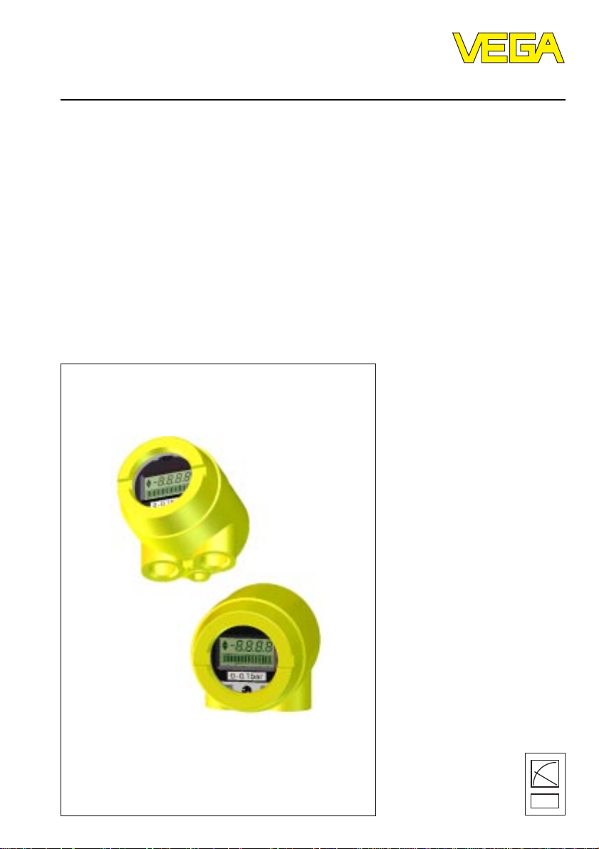
Retrofitting of the display
Indicating module 12 (AM12)
Level and Pressure
8888
Page 2

Contents
Safety information ........................................................................ 2
Note Ex-area ............................................................................... 2
1 Product description
1.1 Function and configuration ................................................. 3
1.2 Technical data ...................................................................... 3
2 Electrical connection ................................................................ 4
3 Set-up
3.1 Indicating and adjustment elements .................................. 5
3.2 Retrofitting of the display .................................................... 6
3.3 Adjustment ........................................................................... 7
Contents
Safety information
The described module must only be inserted
and operated as described in this operating
instruction. Please note that other action can
cause damage for which VEGA does not take
responsibility.
2 Indicating module 12
Note Ex-area
Please note the enclosed approval documents
(yellow binder) and especially the attached
safety data sheet.
Page 3

Product description
1 Product description
1.1 Function and configuration
The display is a digital indicating instrument
without auxiliary energy for mounting to pressure transmitters D84 / D85 with LC-display
for digital and quasianalogue demonstration.
Function
The display enables the indication of values
between -9999 and 9999. The decimal point
can be shifted. The indicated unit can be
chosen individually.
Configuration
The display can be connected to any active
4 … 20 mA-output.
It is suitable for looping into the 4 … 20 mAsignal line of sensors or for connection to all
signal conditioning instruments VEGAMET
with analogue output 4 … 20 mA or to the
processing system VEGALOG with analogue
output card (AA).
1.2 Technical data
Ambient conditions
Ambient temperature -10°C … +70°C
Storage and transport temperature -40°C … +85°C
Temperature er ror ≤ 0,1%/10K (∆I= 16 mA)
Input
Transmission analogue, 4 … 20 mA
Max. input current 150 mA
Connection line to the sensor 2-wire
Voltage loss 4,5 V at 20 mA
Deviating data for certified instruments
The digital indication type AM12 can be mounted in pressure transmitter type D7. Ex,
D8. Ex with integral oscillator E22 HEx, E23 HEx (2. supplement to EC-type approval TÜV
97 ATEX 1250) as well as in pr essure transmitter type D8.Ex0 with integral oscillator E22
HEx0, E 23 HEx0 (2. supplement to EC-type appr oval TÜV 97 A TEX 1249 X). The Ex-technical data of the pressure transmitters with integral digital indication type AM12 change as
follows:
Ci ≤ 7 nF (instead of ≤ 4 nF as previously)
Indicating module 12 3
Page 4

2 Electrical connection
Electrical connection
-
S
1 2 3 4 5
+
4...20mA
12...36 V DC
Z ti
-
Op
+
Indication
AM12
-
Power supply
+
4 Indicating module 12
Page 5

Set-up
3 Set-up
3.1 Indicating and adjustment elements
2
7
8
1
10
5
Fig. 1
Z
Op
S
Z
4...20mA
12V...36V DC
Bedieneinsatz
operating unit
4
E
P
6
3
12
Zum Anschluß an
For connection to
Op
t
i
AM12
VEGA-Auswertgeräte
VEGA-signal conditioning instruments
AM12
Klemmeinsatz
terminal
13
9
11
Fig. 2
1 Connection housing
2 Indicating module
12 Distance pin (1) with lock washer
13 Distance pin (2) without lock washer
3 Screws
4 Rotating switch
5 Plus key
6 Minus key
7 Bargraph indication
8 Digital indication
9 Terminals for indicating module
10 Terminals (supply voltage)
11 Cable entry M 20x1,5
Indicating module 12 5
Page 6

Set-up
Rotating switch
With the rotating switch you choose the appropriate mode.
OPERATE indication of measured value
ZERO adjustment of min. value (4 mA)
END adjustment of max. value (20 mA)
POINT shifting of decimal point
Plus/Minus key
With these two keys you modify the value of
the digital indication. When you keep the key
pushed, the digital indication changes the
value in three speeds. After each 28 steps,
the counting speed increases by one step.
Procedure
• Choose the required mode with the rotating
switch.
• Push one of the two keys, the digital indication (9) starts flashing.
• Push one of the two keys to modify the
value of the digital indication appr opriately.
When the rotating switch is set to "OPERATE" the keys have no function.
• You can save the adjusted value by modifying the position of the rotating switch.
3.2 Retrofitting of the display
• Remove the housing cover and switch off
the voltage.
• Disconnect the instrument and remove the
cable.
• Loosen the screws, remove the insert and
mount the new insert.
When mounting the new insert, proceed as
follows:
• For fastening of the new insert do not use
the screws which you have removed before, but the replacement screws supplied
with the new display.
• Fasten the lower terminal insert and mount
the distance pins like in fig. 2.
• Connect the instruments to terminals 1 and
2.
• Now fasten the indicating module AM12
with the screw (3).
• Connect the connection line as marked to
terminals 4 and 5 (see fig. 1).
• Tighten the screw (3) in fig. 1.
• Scaling see „3.3 Adjustment“.
6 Indicating module 12
Page 7

Set-up
3.3 Adjustment
• The indication required the adjustment of
the values for 4 mA and 20 mA. Proceed as
follows: Set the rotating switch to position
„POINT“ and push one of the keys. The
digital indication starts flashing. By pushing
the keys again you move the decimal point.
The minus key moves the decimal point to
the left, the plus key to the right.
• Set the rotating switch to position „ZERO“
and push the plus key to increase the
indication value or the minus key to reduce
the indication value. When you keep the
key pushed the digital indication modifies
the indication value in three steps with
increasing speed.
• Set the rotating switch to position „END“
and push one of the keys. The digital indication starts flashing. Use the keys to
adjust the indication value.
• Set the rotating switch to position „OPERATE“. All adjusted values ar e transmitted to
an EEPROM-memory and saved. They
remain there even in case of a probable
voltage loss.
• Screw the housing cover .
Indicating module 12 7
Page 8

VEGA Grieshaber KG
Am Hohenstein 113
D-77761 Schiltach
Phone (0 78 36) 50 - 0
Fax (0 78 36) 50 - 201
e-mail info@vega-g.de
ISO 9001
The statements on types, application, use and operating conditions of
the sensors and processing systems correspond to the actual
knowledge at the date of printing.
Technical data subject to alteration.
2.23 126 / Nov. ’98
 Loading...