

Page 1
Operating Instruction
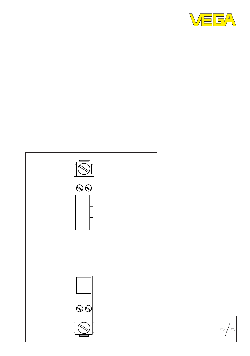
Safety barrier type 9130
1 2
Level and Pressure
160
9001/01-
086/150/10
3 4
out
in
Page 2

1 Application and function
Operating instruction
Safety barrier type 9130 is a passive component. It converts a not-intrinsically safe circuit
without galvanic isolation into an intrinsically
safe circuit.
The term „intrinsically safe“ characterizes a
circuit in which the energy flow is limited and
capacitive as well as inductive energy storage
is saved such that neither switching commands nor shortcircuits can ignite an explosive mixture.
Safety barrier type 9130 takes over this function. It limits the energy flow, damps the capacitance C
output circuit and reduces the saved energy
and the inductance La of the
a
reliably. The saved circuits cannot ignite explosive mixtures.
Example:
An indicating instrument is mounted in Ex-area
and requires an intrinsically safe 0 … 20 mAcurrent signal.
The existing 0 … 20 mA-signal to the indicating instrument however is not intrinsically safe.
Safety barrier type 9130 is connected to the
signal line to supply the indicating instrument
in Ex-area with an intrinsically safe 20 mAsignal. The safety barrier then provides on its
output an intrinsically safe 0 … 20 mA-current
signal for the indicating instrument.
Note:
The capacitance C
output circuit out of the indicating instrument
and the supply line must not exceed the
stated limit values. The standard wiring is
normally within these values.
2 Technical data
General
Mounting place outside Ex-area on C-rail
Operating temperature -20°C … +40°C
Storage and transport temperature -40°C … +75°C
Cross-section area of conductor 1,5 mm
Protection
- terminals IP 20
- housing IP 40
Weight 100 g
Approvals PTB-no. Ex-91.C.2046 X
Classification [EEx ia] II C / [EEx ia] II B
2
(terminals)
and inductance La of the
a
Input circuit
Nominal voltage U
Zener voltage 8,6 V
N
Min. series resistance R
Max. series resistance R
Leakage current against earth at U
N
6 V DC
64 Ω
min
73 Ω
max
≤ 1 µA
Output circuit
Short circuit current I
Capacitance C
Inductance L
Capacitance C
Inductance L
2 Safety barrier type 9130
K
at EEx ib IIC ≤ 7 µF
a
at EEx ia IIC ≤ 1,3 mH
a
at EEx ib IIB ≤ 70 µF
a
at EEx ib IIB ≤ 7 mH
a
≤ 128 mA
Page 3

Operating instruction
3 Dimensions 5 Electrical connection
4 Mounting
• Plug the safety barrier outside the hazardous area to a C-rail.
• Connection the potential equalization line out
of the Ex-area to the PA-terminal.
• Connect the intrinsically safe circuit (blue)
correctly to position on the safety barrier
which is marked blue. Note the polarity.
• Now connect the not-intrinsically safe circuit
correctly to the upper side (white) of the
safety barrier. Wrong polarity destroys the
safety barrier.
Note:
Lines in Ex-areas must be marked blue along
their entire length.
Ex-area
0 … 20 mA-output
circuit (intrinsically
safe)
e.g. indicating instrument
Not Ex-area
+
1 2
160
9001/01-
086/150/10
3 4
+
–
–
+
U
N
–
0 … 20 mA-input
circuit (not intrinsically safe)
Safety barrier type 9130 3
Page 4

VEGA Grieshaber KG
Am Hohenstein 113
D-77761 Schiltach
Phone (0 78 36) 50 - 0
Fax (0 78 36) 50 - 201
e-mail vega@vega-g.de
Safety information
The described module must only be installed
and operated as described in this operating
instruction. Please note that other action can
cause damage for which VEGA does not take
responsibility.
ISO 9001
The statements on types, application, use and operating conditions of the
sensors and processing systems correspond to the actual knowledge at
the date of printing.
Technical data subject to alteration
2.11 997 / June ’98
 Loading...