

Page 1
CK-200 Instruction Manual Electronic CW Keyer
Introduction
The CK-200 Electronic CW Keyer is a microprocessor controlled keyer that
provides iambic key operation and dot-and-dash memory to make sending
perfect code easier. It has tunable code speed, code weight, and sidetone
frequency; it supports both direct and grid-block keying outputs as well as relay
contact output. You also get to choose between type A and type B iambic
keying.
Control Functions
VECTRONICS
ON
OFF
IAM BICTUNE
A
B
OFF
ON
TM
SPEED
MODEL CK-200
ELECTRO NIC KEYER
KEYING
+
RELAY
1234 5(LED)
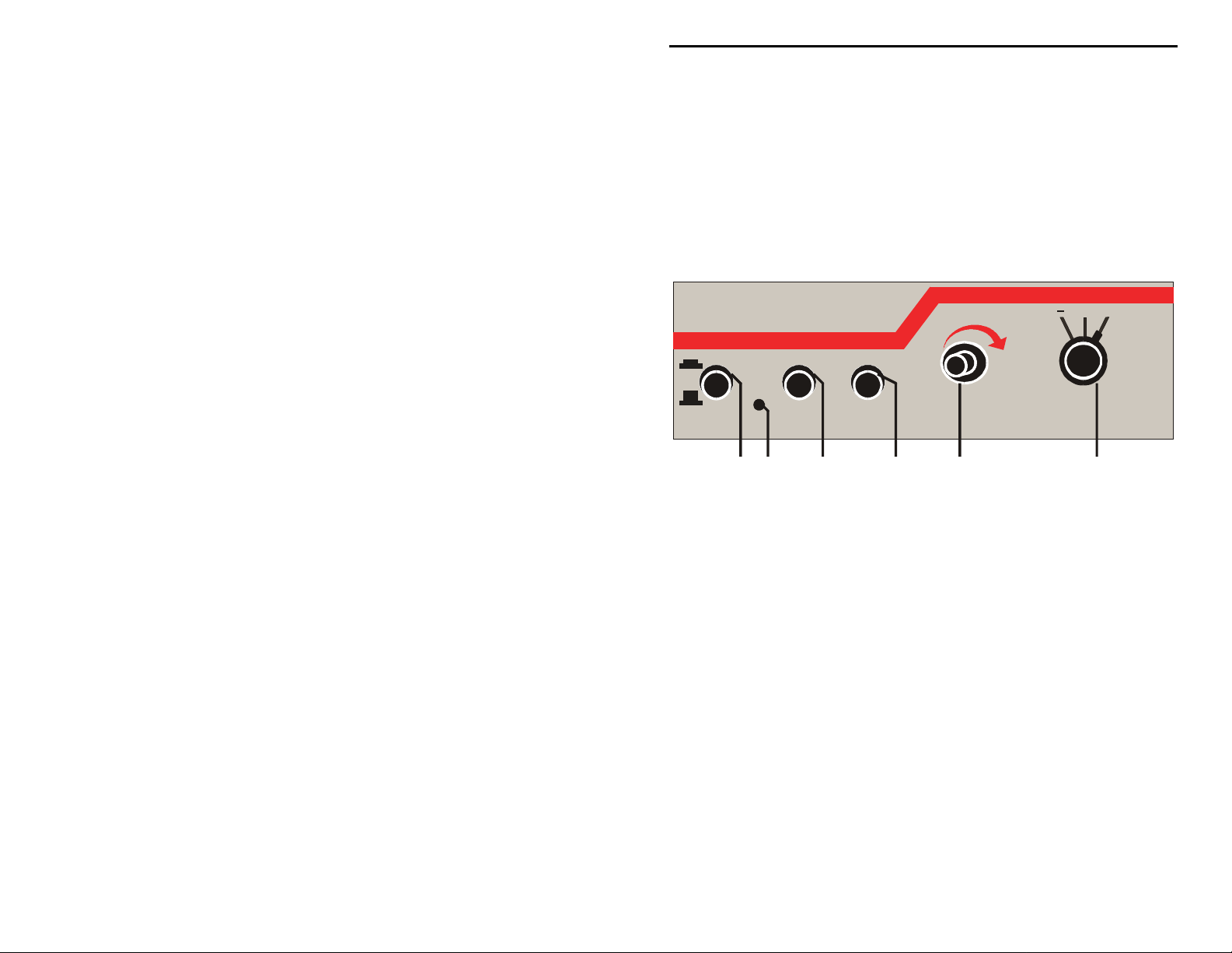
Figure 1. CK-200 Front Panel.
1. The On/Off button turns the unit ON and OFF. The LED lig hts when the
unit is ON.
2. The Iambic button selects type A or type B iambic keying. When a
squeeze is released during an element (dot or dash), type B adds the
opposite element. Type A just finishes the element in progress and does not
produce a following alternate element. For example, in type A iambic, a
squeeze release during the "dah" in the letter A will produce "di- dah" (A).
In type B iambic, a squeeze release during the "dah" in the letter A will
produce "di-dah-dit" (R).
3. The Tune button continuously keys the transmitter for tuning.
4. The Speed control varies the code speed. The speed range is configured
with an internal jumper (JMP1) for 5 to 65 WPM or 10 to 40 WPM. Turn
the control clockwise to increase speed and counter-clockwise to decrease
speed. The unit is factory set to 5 to 65 WPM with JMP1 at the "L"
position. To make the speed adjustment less sensitive, change the speed
range to the narrower range of 10 to 40 WPM. To change the speed range,
1
Page 2
CK-200 Instruction Manual Electronic CW Keyer
remove the cover by removing the two screws (one on each side) that secure
it. Locate jumper JMP1 behind the microprocessor and set it to the "H"
position.
5. The Keying rotary switch selects output for negative (grid-block), positive
(direct), or relay contact output.
6. The Weight control varies the code weight from approximately 25% to
75%, with the standard dot defined as 50% weight. The standard dot-dashspace ratio is 1:3:1 (trimpot at mid-range). The unit is factory set to
standard weight of 50%. To change the code weight, remove the cover by
removing the two screws (one on each side) that secure it. Locate trimpot
R27 next to jumper JMP1; turn it clockwise to increase dot and dash lengths
and counter-clockwise to decrease dot and dash lengths.
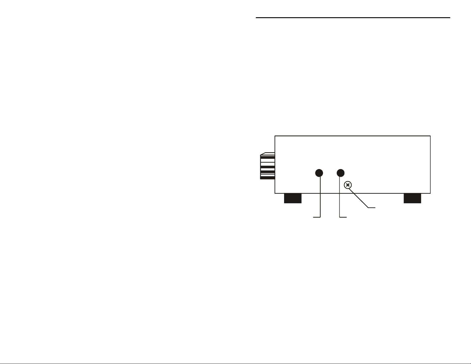
FRONT
REAR
COVER SCREW (2)
VOLUME CONTROL PITCH CONTROL
Figure 2. CK-200 Right Side.
7. The Volume control adjusts the sidetone level of the internal speaker. This
control is located internally. When looking at t he unit's front panel, it is
accessible through a small hole on the right side, closest to the front and
may be adjusted by inserting a small flat-headed screwdriver. This control
is turned clockwise to increase the volume and counter-clockwise to
decrease the volume.
8. The Pitch control sets the desired sidetone pitch from approximately 300 to
1200 Hz. This control is also located internally. When looking at the unit's
front panel, it is accessible through a small hole on the right side, closest to
the rear and may be adjusted by inserting a small flat-headed screwdriver.
This control is turned clockwise to raise the pitch and counter-clockwise to
lower the pitch.
2
Page 3

CK-200 Instruction Manual Electronic CW Keyer
Rear Panel
CK200 Electronic Keyer
OUTPUT
POSITIVE RELAY NEGATIVE KEYER PADDLE 9 VDC
12 3 4 5
VECTRONICS
AC ADAPTER
Figure 3. CK-200 Rear Panel.
1. Positive Keying O utput jack is a 3.5 mm stereo jack that accepts a stereo
or mono plug where the keying output is available only at the tip of the plug
(the ring of the plug is not connected).
2. Relay Keying Output jack is a 3.5 mm stereo jack that accepts a stereo
plug where the tip and ring of the plug form output contact.
3. Negative Keying Output jack is a RCA phono jack where the keying
output is available at the center pin of the plug.
4. Keyer Paddle jack is a ¼ inch stereo jack where the tip is connected to the
dot level and the ring is connected to the dash level.
5. Power jack is a 2.1 mm coaxial jack with positive center and negative
sleeve that accepts 9 to 16 volts DC power supply. Use of this jack
disconnects the internal 9-volt battery.
Installation
1. A 9-volt battery (not included) may be installed. Remove the cover by
removing the two screws (one on each side) that secure it. A battery holder,
located inside the enclosure, is provided for installing a 9-volt battery.
2. A 12 Vdc power supply may also be used to power the CK-200. A 2.1 mm
coaxial plug with a positive center and a negative sleeve should be used to
power this unit. The MFJ-1312B, an optional 12 volts adapter, is available
from MFJ Enterprises, Inc. The battery is automatically disconnected when
external power is used.
3
Page 4

CK-200 Instruction Manual Electronic CW Keyer
3. If weight control adjustment is required, access the trimpot located next to
jumper JMP1 and adjust as desired.
4. A squeeze key with ¼-inch stereo phono plug and a two-conductor shielded
cable should be used. If separate shielded cables are used, the two shields
should be tied together and connected to ground. The dot wire should be
connected to the tip of the plug and the dash wire to the ring (reverse this
for left-handed operator).
DOT
DASH
DASH
DOT
Twin Level (Iambic) Paddle
DOT DASH
DOT
DASH
Single Level Padd le
Figure 4. Pa ddle Plug.
5. Keying output circuit allows keying of grid-block and solid state
transmitters. Negative output keying is provided on a RCA phono jack.
Relay output keying is provided on a 3.5 mm stereo jack where the tip and
ring of the plug form output contact. Positive output keying is provided on
a 3.5 mm stereo jack where keying is available only from the tip of the plug;
as a result, a mono plug can also be used here.
Note: Consult the transmitter's instruction manual to determine which
output to use. When in doubt, use the relay contact output.
Figure 5. Relay Keying Output Plug.
4
Page 5

CK-200 Instruction Manual Electronic CW Keyer
RING
TIP (+) RING
GROUND
TIP (+)
Figure 6. Positive Keying Output Plug.
Keyer Operation
1. A 9-volt battery or an optional dc adapter may be used to supply power to
the keyer.
2. The key paddle should be connected to the Keyer Paddle jack on the rear
panel of the unit. A dual paddle squeeze key should be used.
3. Next, the keyer should be turned on with the On/Off switch. The LED
should light up.
4. The user should now start sending with the paddle and adjust speed, pitch,
and volume as desired. If you have sidetone on your transmitter/transceiver
you may turn off the volume completely to eliminate hearing two sidetones
at the same time and to reduce battery drain.
Note: The higher the volume, the more drain there will be on the battery.
5. The dot and dash memories make sending easier. The memories allow the
user to key a dot before the completion of a dash and vice versa. This
feature can be checked by setting the keyer to the lowest speed and tapping
first the dash lever and then the dot lever before the completion of the dash.
The keyer will provide both the dash and the dot. The dash memory can be
checked in a similar manner. The dot insertion feature allows the user to
insert a dot by tapping the dot lever while holding the dash lever in. The
dash insertion feature allows the user to insert a das h while holding the dot
lever in. The Iambic operation allows sending of alternate dots and dashes
when using squeeze key and with both paddles squeezed. The first paddle
contacted will determine whether a dot or dash occurs first.
6. The user may select either iambic A or B according to his or her preference.
5
Page 6

CK-200 Instruction Manual Electronic CW Keyer
Morse Code Character Set
1
A di-dah
B dah-di-di-dit – • • • O dah-dah-dah – – –
C dah-di-dah-dit – • – • P di-dah-dah-dit • – – •
D dah-di-dit – • • Q dah-dah-di-dah – –
E dit
F di-di-dah-dit
G dah-dah-dit – – • T dah –
H di-di-di-dit
I di-dit
J di-dah-dah-dah • – – – W di-dah-dah
K dah-di-dah – • – X dah-di-di-dah – • • –
L di-dah-di-dit
M dah-dah – – Z dah-dah-di-dit – – • •
1 di-dah-dah-dah-dah • – – – – 6 dah-di-di- d i- di t – • • • •
2 di-di-dah-dah-dah • • – – – 7 dah-dah-di-di-dit – – • • •
3 di-di-di-dah-dah • • • – – 8 dah- dah-dah-di - d it – – – • •
4 di-di-di-di-dah • • • • – 9 dah-dah-dah-dah-dit – – – – •
5 di-di-di-di-dit • • • • • 0 dah-dah-dah-dah-da h – – – – –
Period [.] di-dah-di-dah-di-dah
Comma [,] dah-dah-di-di-dah-dah – –
Question Mark or Request for Repetition [?] di-di-dah-dah-di-dit
Fraction Bar or Slash Bar [/] dah-di-di-dah-dit – • • – •
End of Message, Plus Si gn, or Cross [+] di-dah-di-dah-dit
End of Work di-di-di-dah-di-dah
Double Dash, Equal Sign, Pause, or Break [=] dah-di-di-di-dah – • • • –
Semicolon [;] dah-di-dah-di-dah-dit –
Colon [:] dah-d ah-dah-di-di-dit – – – • • •
Apostrophe ['] di-dah-dah-dah-dah-dit
Quotation Mark ["] di-dah-di-di-dah-dit
Hyphen or Dash [-] dah-di-di-di-di-dah – • • • • –
Underline [_] di-di-dah-dah-di-dah
Dollar Sign [$] di-di-di-dah-di-di-dah
Left Parenthesis or Go Only [(] dah-di-dah-dah-dit – • – – •
Right Parenthesis [)] dah-di-dah-dah-di-da h – • – – • –
Wait or Stand By di-dah-di-di-dit
Understood di-di-di-dah-dit
Starting Signal dah-di-dah-di-dah – • – • –
Error di-di-di-di-di-di-di-dit
Paragraph [¶] di-dah-di-dah-di-dit
Invitation to Transmit or Go Ahead [K] dah-di-dah – • – K
1.
FCC test require ment co nsists t he 26 let ters, the 10 nu merals, the per iod, the c omma, t he quest ion mark ,
frac tion ba r DN.
– N dah-dit – •
•
–
– –
•
– –
– –
•
•
AAA
MIM
IMI
R di-dah-dit • – •
•
– • S di-di-dit • • •
• •
U di-di-dah • • –
• • • •
V di-di-di-dah • • • –
• •
– • • Y dah-di-dah-dah –
•
– • – • –
•
• •
– – • •
• •
DN
– • – •
•
• • •
– • –
AR
SK
BT
– • – •
•
KR
OS
– – – – •
•
– • • – •
•
WG
AF
DU
• •
• • •
– – • –
– • • –
IQ
SX
KN
KK
– • • •
•
• • •
– •
AS
SN
KA
HH
• • • • • • • •
– • – • •
•
AL
AR, SK, BT
and
6
Page 7

CK-200 Instruction Manual Electronic CW Keyer
Signals Used In Other Radio Services
Interrogatory di-di-dah-di-dah
Emergency Silence di-di-di-di-dah-dah
Executive Follows di-di-dah-di-di-dah
Break-in Sig nal dah-dah-dah-dah-dah – – – – –
Emergency Signal di-di-di-dah-dah-dah-di-di-dit
Relay of Distress dah-di-di-dah-di-di-dah-di-dit – • • – • • – • •
– • – INT
• •
– –
• • • •
– • • –
• •
– – – • • •
• • •
HM
IX
TTTTT
SOS
DDD
Technical Assistance
If you have any problem with this unit first check the appropriate section of this
manual. If the manual does not reference your problem or your problem is not
solved by reading the manual you may call VECTRONICS at 662-323-5800.
You will be best helped if you have your unit, manual and all information on
your station handy so you can answer any questions the technicians may ask.
You can also send questions by mail to VECTRONICS, 300 Industrial Park
Road, Starkville, MS 39759 or by Fax to 662-323-6551. Send a complete
descriptio n of your p roblem, an e xplanation o f exactly ho w you are using your
unit, and a complete description of your station.
7
Page 8

CK-200 Instruction Manual Electronic CW Keyer
Schematic
8
 Loading...