

Page 1

AT-100 Active Antenna
AT-100
ACTIVE ANTENNA
Owner's Manual
FEATURES
The compact Vectronics AT-100 Active Antenna provides amplified reception
of broadcast, short wave, or amateur radio signals from 300 KHz to 40 MHz. It
can be used with the supplied telescoping antenna or with an external wire
antenna of your choice.
reception, both at home, and as a portable unit in the field.
The AT-100 provides gain, selectivity, and better
SPECIFICATIONS
Front Panel Indicators
ON/OFF
Front Panel Controls
Gain Control
Bypass Switch
Band Switch
Peak - Tune Control
LED mounted on the front panel (activated when a
band is selected with the Band switch).
Adjusts Gain from -10 dB to +10 dB
Selects bypass mode
Six Position for OFF and 5 Bands from. 3 MHz to 40
MHz
Maximizes the Gain for each of the 5 Bands
Rear Panel Connectors
Input
Output
AC Adapter IN
Ground
Other
Frequency Coverage
Antenna
Dimensions
Weight
SO-239 Connector
SO-239 Connector
9-12 VDC Input @ 45 mA (3.5 mm plug)
Wing-nut, rear panel
300 KHz to 40 MHz
20" Telescoping Antenna - mounted through hole in
the top (connected to input SO-239 connector).
external wire antenna plugged into the SO-239 input
requires the removal of the telescoping antenna.
2.5" H x 6.4" W x 3.3" D
1 lb.
An
1
Page 2
A T-100 Active Antenna
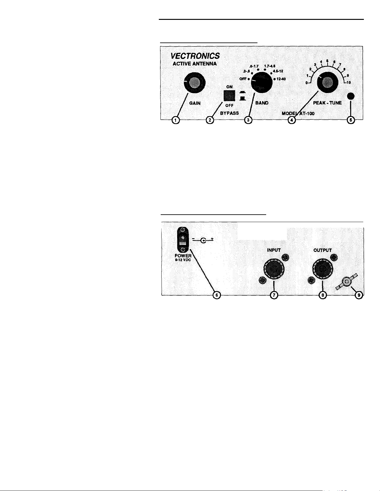
FRONT PANEL CONTROLS
1.
GAIN CONTROL:
2.
BYPASS SWITCH:
3.
PEAK - TUNE CONTROL: Optimizes Peak Tuning for each of the 5
4.
BAND SWITCH:
5.
POWER LED
Adjust the gain of the AT-100 from -10 dB
to +10 dB.
Connects the Input SO-239 directly to the
Output SO-239.
bands.
Power rotary switch that selects the 5 bands
from 300 KHz to 30 MHz.
Illuminates when power is on.
Owner's Manual
REAR PANEL CONNECTIONS
VECTRONICS(R)
STARKVILLE, MS USA
6.
POWER:
2
3.5mm
barrel connector for power to AT-100 9-12
VDC with center positive. Inserting the plug into
the rear jack automatically disconnects the internal
battery.
adapter (AC-12).
Vectronics offers an optional 12 VDC
Page 3

AT-100 Active Antenna
7.
INPUT:
8.
OUTPUT:
9.
GROUND:
Either wire antenna or telescoping antenna on the
top cover.
connected to the spacer where the telescoping
antenna will be used.
SO-239 connector for output to radio receiver.
Post/Wing-nut type ground connector.
(Not both at the same time.)
Owner's Manual
Input is
OPERATION
Carefully unpack your AT-100 from the packing carton and inspect it for signs
of damage. If any damage is apparent, notify the transportation carrier or
dealer immediately.
storing, or reshipping the tuner.
I
nstallation Procedures
1.
You may connect either the telescoping antenna provided or an external
wire antenna of your choice. To connect the telescoping antenna; screw the
antenna end through the top cover and into the spacer located on the PC
board. If you chose to use external wire antenna; plug it into the INPUT
SO-239 connector located on the back of the unit.
BOTH ANTENNAS CONNECTED AT THE SAME TIME!)
2.
Connect a cable from the output of the AT-100 to your receiving equipment.
We recommend keeping the packing carton for moving,
(DO NOT HAVE
3.
Connect a wire (#18 ga. approx.) from the wing-nut ground to the receiver
ground which, in turn, should be connected to an earth ground. If the unit
is operated in a portable application, this ground need not be connected.
Tuning
1.
Make sure the AT-100 BYPASS switch is in the ON position.
2.
Select the band and frequency of desired operation on your receiving
equipment.
3.
Set the GAIN and POWER controls on your receiving equipment to the
desired settings before applying power to the AT-100.Actual setting may
vary from antenna to antenna.
4.
Turn the AT-100 GAIN control full counter-clockwise.
5.
Set the AT-100 BAND Selector Switch to the selected band. The red LED
will light.
3
Page 4

AT-100 Active Antenna
6.
Turn the BYPASS switch off.
7. Increase the GAIN Control to approximately midway (12 o'clock).
8.
Rotate the PEAK - TUNE Controls for maximum noise or signal as heard
on your receiver.
9.
You will notice that pushing the BYPASS Switch to the "ON" position
while listening to a station bypasses the gain and selectivity stages of the
AT-100.
back "OFF" will raise the level of received signals which will be determined
by:
(A) GAIN CONTROL ADJUSTMENT
(B) PEAK - TUNE ADJUSTMENT
(C) PROPER BAND SELECTION
10.
With some antennas connected externally to the AT-100, a high GAIN
setting may make the unit appear to chirp or whistle as the PEAK - TUNE
is rotated.
disappear.
Notes
1.
Connection of the AC Adapter automatically disconnects the internal
battery.
2.
Use a Heavy Duty 9V alkaline battery.
This will decrease the received noise level. Turning the bypass
Turn down the GAIN adjustment until these are removed or
Owner's Manual
3.
Use
4.
only the amount of gain needed
Never
use an external antenna and the telescoping antenna at the same time.
to receive the desired station.
TECHNICAL ASSISTANCE
If you have any problem with this unit first check the appropriate section of this
manual. If the manual does not reference your problem or your problem is not
solved by reading the manual you may call VECTRONICS at 662-323-5800.
You will be best helped if you have your unit, manual and all information on
your station handy so you can answer any questions the technicians may ask.
You can also send questions by mail to VECTRONICS, 300 Industrial Park
Road, Starkville,
description of your problem, an explanation of exactly how you are using your
unit, and a complete description of your station.
4
MS 39759 or by Fax to 662-323-6551. Send a complete
Page 5

 Loading...