


 Loading...
Manual
FlexRay Interface Family
VN3300/VN3600/VN7600
Version 2.0
English
Imprint
Vector Informatik GmbH
Ingersheimer Straße 24
D-70499 Stuttgart
The information and data given in this user manual can be changed without prior notice. No part of this manual may be reproduced in any form or by any means without the written permission of the publisher, regardless of which method or which instruments, electronic or mechanical, are used. All technical information, drafts, etc. are liable to law of copyright protection.
© Copyright 2010, Vector Informatik GmbH. Printed in Germany. All rights reserved.
Art. 80310

Manual |
Introduction |
|
|
Table of contents
1 |
Introduction |
3 |
|
1.1 |
About this User Manual |
4 |
|
|
1.1.1 |
Access Help and Conventions |
4 |
|
1.1.2 |
Certification |
5 |
|
1.1.3 |
Warranty |
5 |
|
1.1.4 |
Support |
5 |
|
1.1.5 |
Registered Trademarks |
5 |
2 |
FlexRay Interface Family |
7 |
|
2.1 |
Common Features |
8 |
|
2.2 |
Synchronization |
8 |
|
2.3 |
Trigger |
|
9 |
2.4 |
Main Connectors |
10 |
|
2.5 |
Technical Data |
11 |
|
2.6 |
VN3300 |
|
12 |
|
2.6.1 |
Connectors |
12 |
2.7 |
VN3600 |
|
13 |
|
2.7.1 |
Connectors |
13 |
|
2.7.2 |
LED Display |
14 |
2.8 |
VN7600 |
|
15 |
|
2.8.1 |
Connectors |
15 |
|
2.8.2 |
LED Display |
16 |
3 |
Hardware installation |
17 |
|
3.1 |
General Information |
18 |
|
|
3.1.1 |
VN3300 |
18 |
|
3.1.2 |
VN3600/VN7600 |
18 |
3.2 |
Replacing Piggybacks |
19 |
|
|
3.2.1 |
VN3300 |
19 |
|
3.2.2 |
VN3600/VN7600 |
20 |
4 |
Accessories |
23 |
|
4.1 |
Piggybacks |
24 |
|
4.2 |
Cables |
|
24 |
|
4.2.1 |
FRcable A |
24 |
|
4.2.2 |
FRcable AB |
25 |
|
4.2.3 |
SYNCcableXL |
25 |
4.3 |
Miscellaneous |
26 |
|
|
4.3.1 |
FRterm |
26 |
5 |
Appendix A: Addresses |
27 |
|
© Vector Informatik GmbH |
Version 2.0 |
- I - |

Manual |
Introduction |
|
|
1 |
Introduction |
|
||
In this chapter you find the following information: |
|
|||
|
|
|
|
|
1.1 |
|
|
|
page 4 |
|
About this User Manual |
|||
Access Help and Conventions
Certification
Warranty
Support
Registered Trademarks
© Vector Informatik GmbH |
Version 2.0 |
- 3 - |
Introduction |
Manual |
|
|
1.1About this User Manual
1.1.1 Access Help and Conventions
To find information quickly
Conventions
The user manual provides you the following access help:
¼ At the beginning of each chapter you will find a summary of the contents,
¼In the header you can see in which chapter and paragraph you are ((situated)),
¼In the footer you can see to which version the user manual replies.
In the two following charts you will find the conventions used in the user manual regarding utilized spellings and symbols.
|
Style |
Utilization |
|
|
|
bold |
Blocks, surface elements, windowand dialog names of the soft- |
||
|
|
|
ware. Accentuation of warnings and advices. |
|
|
|
|
[OK] |
Push buttons in brackets |
|
|
|
File | Save |
Notation for menus and menu entries |
|
Windows |
Legally protected proper names and side notes. |
||
|
Source code |
File name and source code. |
||
|
|
|
Hyperlinks and references. |
|
|
Hyperlink |
|||
|
|
|
||
|
<STRG>+<S> |
Notation for shortcuts. |
||
Symbol |
Utilization |
|
This symbol calls your attention to warnings. |
|
|
|
Here you can find additional information. |
|
|
|
Here is an example that has been prepared for you. |
|
|
|
Step-by-step instructions provide assistance at these points. |
|
|
|
Instructions on editing files are found at these points. |
|
|
|
This symbol warns you not to edit the specified file. |
|
|
- 4 - |
Version 2.0 |
© Vector Informatik GmbH |

Manual |
Introduction |
|
|
1.1.2 |
Certification |
|||
Certified Quality |
Vector Informatik GmbH has ISO 9001:2008 certification. The ISO standard is a glob- |
|||
Management System |
ally recognized standard. |
|||
1.1.3 |
Warranty |
|
|
|
Restriction |
We reserve the right to change the contents of the documentation and the software |
|||
of warranty |
without notice. Vector Informatik GmbH assumes no liability for correct contents or |
|||
|
|
damages which are resulted from the usage of the user manual. We are grateful for |
||
|
|
references to mistakes or for suggestions for improvement to be able to offer you |
||
|
|
even more efficient products in the future. |
||
1.1.4 |
Support |
|
|
|
You need support? |
You can get through to our support at the phone number |
|||
|
|
+49 711 80670-200 or by fax |
||
|
|
+49 711 80670-111 |
|
|
|
|
E-Mail: |
|
|
|
|
support@vector.com |
||
1.1.5 |
Registered Trademarks |
|||
Registered |
All trademarks mentioned in this user manual and if necessary third party registered |
|||
trademarks |
are absolutely subject to the conditions of each valid label right and the rights of par- |
|||
|
|
ticular registered proprietor. All trademarks, trade names or company names are or |
||
|
|
can be trademarks or registered trademarks of their particular proprietors. All rights |
||
|
|
which are not expressly allowed, are reserved. If an explicit label of trademarks, |
||
which are used in this user manual, fails, should not mean that a name is free of third party rights.
¼ Windows, Windows XP, Windows Vista, Windows 7 are trademarks of the Microsoft Corporation.
© Vector Informatik GmbH |
Version 2.0 |
- 5 - |

Manual |
FlexRay Interface Family |
|
|
2 FlexRay Interface Family
In this chapter you find the following information:
2.1 |
Common Features |
|
page |
8 |
|||||||
2.2 |
|
|
|
|
|
|
|
|
page |
8 |
|
Synchronization |
|||||||||||
2.3 |
|
|
|
|
|
|
|
page |
9 |
||
Trigger |
|||||||||||
2.4 |
|
|
|
|
|
|
page 10 |
||||
Main Connectors |
|||||||||||
2.5 |
|
|
|
|
|
page 11 |
|||||
Technical Data |
|||||||||||
2.6 |
|
|
|
|
page 12 |
||||||
VN3300 |
|||||||||||
|
|
|
|
|
|
||||||
|
Connectors |
|
|
||||||||
2.7 |
|
|
|
page 13 |
|||||||
VN3600 |
|||||||||||
|
|
|
|
|
|
||||||
|
Connectors |
|
|
||||||||
|
|
|
|
|
|||||||
|
LED Display |
|
|
||||||||
2.8 |
|
|
page 15 |
||||||||
VN7600 |
|||||||||||
|
|
|
|
|
|||||||
|
Connectors |
|
|
||||||||
|
|
|
|
|
|||||||
|
LED Display |
|
|
||||||||
|
|
|
|
|
|
|
|
|
|
|
|
© Vector Informatik GmbH |
Version 2.0 |
- 7 - |

FlexRay Interface Family |
Manual |
|
|
2.1Common Features
FlexRay Interfaces for PCI and USB
Further properties
The FlexRay Interface Family offers a future-proofed and powerful solution for development, simulation, test, measurement or calibration of FlexRay networks through an FPGA-based FlexRay communication controller.
The devices have a fast 32 bit microcontroller (312 MHz) and allow, besides the ability of transmitting and receiving of data and null frames, the detection of invalid frames on the bus. Future features can also be added in the field by FPGA updates.
¼ Simulation of comprehensive networks due to the 2 MB transmission
|
¼ Time synchronization of multiple devices of the FlexRay or XL Interface Family |
||
|
¼ Cycle multiplexing |
||
|
¼ Trigger input and output |
||
|
¼ Supports 254 byte maximum payload |
||
|
¼ In-cycle response |
||
|
¼ Hardware-based incrementing of a payload area |
||
|
¼ Startup monitoring |
||
|
¼ FlexRay-Driver-Library for creating own applications |
||
Configuration |
The Vector Hardware Configuration tool (see Start | Settings | Control Panel | |
||
|
Vector Hardware) enables the configuration of the devices. Further details can be |
||
|
found in the installation instructions. |
||
Bus types |
The connection of the devices to the FlexRay bus is done by transceivers that are |
||
|
available as plug-in boards (Piggybacks). A list of available FRpiggies can be found in |
||
|
chapter |
Piggyback |
on page 24. |
2.2Synchronization
Software/hardware synchronization
Functionality of hardware synchronization
The time stamps, which are created during a measurement by devices of the FlexRay Interface and XL Family, can be synchronized by software or hardware.
The software synchronization is driver-based and available for all applications without any restrictions. The software synchronization can be enabled in Vector Hardware Config | General information | Settings | Software time synchronization. The accuracy of the time stamp correction depends on the device and is typically 50 µs.
The hardware synchronization of maximum four devices is done through the SYNCcable (see description below) and has to be supported by the application. The accuracy of the time stamp correction depends on the application and is typically 1 µs.
The devices to be synchronized must be interconnected by a party line (two-wire bus; signals: SYNC and GND).
At each high-low edge of the sync line the Vector device generates a time stamp that is provided to the application via the driver. This allows the application to synchronize the time stamps of different devices to a common time base.
The synchronization edges can be generated by the devices of the FlexRay Family or other devices of the XL Family.
- 8 - |
Version 2.0 |
© Vector Informatik GmbH |
Manual |
FlexRay Interface Family |
|
|
|
Info: The time synchronization must be supported by the application. For further infor- |
||
|
mation please refer to the relevant manual. Please note that the time synchronization |
||
|
of the driver must be disabled, if multiple devices of the FlexRay and XL Family are |
||
|
being operated on a PC and interconnected via the synchronization line (see Vector |
||
|
Hardware Config | General information | Settings | Software time synchroni- |
||
|
zation). |
||
Synchronization by |
The devices have a time synchronization signal at pin 2 of the 3-pin Binder connector. |
||
Binder connector |
You can connect devices of the Vector FlexRay or XL Family with the SYNCcableXL |
||
|
(see chapter |
SYNCcableXL |
on page 25) to this pin. |
Synchronization by |
The synchronization of multiple VN3300 can be done either through the Binder con- |
||
sync connector |
nector outside the PC housing or by the internal sync connector. The internal sync |
||
|
connector is a 10-pin connector (90° offset) and available next to the Piggyback slot. |
||
|
The synchronization is done through a ribbon cable with a 10-pin standard socket. |
||
|
|
||
|
Info: Synchronization through the Binder and sync connector at the same time is not |
||
|
possible. |
||
2.3Trigger
Trigger inputs |
The devices of the FlexRay Family have a trigger connector each with four lines (see |
|||||
and outputs |
the according pin assignment). Pin 2 is an independent trigger input and pin 3 an |
|||||
|
independent trigger output. Pin 4 and 5 can be used as trigger input as well as trigger |
|||||
|
output. The configuration of the triggers and their actions is set in the application |
|||||
|
(e. g. CANoe). The following picture depicts the internal circuit of pin 4 and 5. |
|||||
|
|
|
|
|
|
|
|
|
|
|
|
|
|
|
|
|
|
|
|
|
|
|
|
|
|
|
|
|
|
|
|
|
|
|
|
|
|
|
|
|
|
|
|
|
|
|
|
|
|
|
|
|
|
|
|
Pin 4 and 5 used for trigger input
If pin 4 and 5 are being used for trigger input, the trigger will be fired by a falling edge on the trigger line. The trigger is processed inside the application. If the trigger input is being wired, the internal 4.7 kOhm resistor must be kept in mind.
© Vector Informatik GmbH |
Version 2.0 |
- 9 - |

FlexRay Interface Family |
|
|
|
|
|
|
|
|
|
Manual |
||
|
|
|
|
|
|
|
|
|
|
|
|
|
|
|
|
|
|
|
|
|
|
|
|
|
|
|
|
|
|
|
|
|
|
|
|
|
|
|
|
|
|
|
|
|
|
|
|
|
|
|
|
|
|
|
|
|
|
|
|
|
|
|
|
|
|
|
|
|
|
|
|
|
|
|
|
|
|
|
|
|
|
|
|
|
|
|
|
|
|
|
|
|
|
|
|
|
|
|
|
|
|
|
|
|
|
|
|
|
|
|
|
|
|
|
|
|
|
|
|
|
|
|
|
|
|
|
|
|
|
|
|
|
|
|
|
|
|
|
|
|
|
|
|
|
|
|
|
|
|
|
|
|
|
|
|
|
|
|
|
|
|
|
|
|
|
|
|
|
|
|
|
|
|
|
|
|
|
|
|
|
|
|
|
|
|
|
|
|
|
|
|
|
|
|
|
|
|
|
|
|
|
|
|
|
|
|
|
Pin 4 and 5 used for |
If pin 4 and 5 are being used for trigger output, the trigger of the application releases |
||||||||||
trigger output |
a falling edge on the trigger line. By using external pull up resistors, the maximum |
||||||||||
|
allowed load is 5 mA. |
||||||||||
|
|
|
|
|
|
|
|
|
|
|
|
|
|
|
|
|
|
|
|
|
|
|
|
|
|
|
|
|
|
|
|
|
|
|
|
|
|
|
|
|
|
|
|
|
|
|
|
|
|
|
|
|
|
|
|
|
|
|
|
|
|
|
|
|
|
|
|
|
|
|
|
|
|
|
|
|
|
|
|
|
|
|
|
|
|
|
|
|
|
|
|
|
|
|
|
|
|
|
|
|
|
|
|
|
|
|
|
|
|
|
|
|
|
|
|
|
|
|
|
|
|
|
|
|
|
|
|
|
|
|
|
|
|
|
|
|
|
|
|
|
|
|
|
|
|
|
|
|
|
|
|
|
|
|
|
|
|
|
|
|
|
|
|
|
|
|
|
|
|
|
|
|
|
|
|
|
|
|
|
|
|
|
|
|
|
|
|
|
|
|
|
2.4Main Connectors
D-SUB9 connector The devices have a FlexRay connector (channel A and B) which is available as D-SUB9 (male). The pin assignment is as follows:
|
Pin |
|
|
Assignment |
|
|
|
|
|
|
|
|
|
|
|
|
|
|
|
|
|
||
1 |
|
|
N.C. |
|
|
|
|
|
|
||
|
|
|
|
|
|
|
|
|
|
|
|
2 |
|
BM Channel A |
|
|
|
|
|
|
|||
|
|
|
|
|
|
|
|||||
|
|
|
|
|
|
|
|
|
|
||
3 |
|
|
GND |
|
|
|
|
|
|
||
|
|
|
|
|
|
|
|
||||
|
|
|
|
|
|
|
|
|
|||
4 |
|
BM Channel B |
|
|
|
|
|
|
|||
|
|
|
|
|
|
|
|||||
|
|
|
|
|
|
|
|||||
5 |
|
|
Shield |
|
|
|
|
|
|
||
|
|
|
|
|
|
|
|
||||
|
|
|
|
|
|
|
|
|
|
||
6 |
|
|
N.C. |
|
|
|
|
|
|
||
|
|
|
|
|
|
|
|
|
|||
7 |
|
BP Channel A |
|
|
|
|
|
|
|||
8 |
|
BP Channel B |
|
|
|
|
|
|
|||
|
|
|
|
|
|
|
|
|
|||
9 |
|
VB+ |
|
|
|
|
|
|
|||
- 10 - |
Version 2.0 |
© Vector Informatik GmbH |
Manual |
FlexRay Interface Family |
|
|
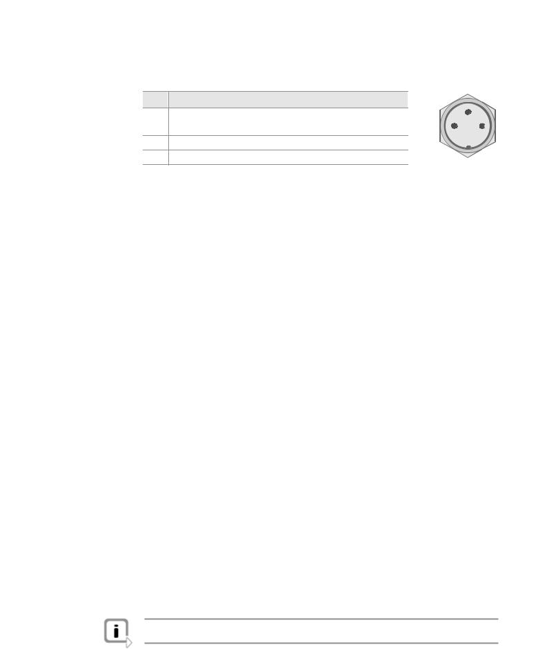
Binder connector |
The pin assignment of the Binder connector is as follows: |
|
|
||
|
Pin |
Assignment |
|
|
|
|
1 |
VN3300 |
: N.C. |
|
2 |
|
|
VN3600/7600 |
: power supply |
|
|
|
|
3 |
1 |
||
|
2 |
Synchronization line (low active) |
|||
|
|
|
|||
|
3 |
GND of voltage supply and sync line |
|
|
|
2.5 |
Technical Data |
|
|
|
|
|
|
|
|
Microcontroller |
Intel PXA270 (312 MHz) |
|
|
FlexRay communication- |
Bosch E-Ray |
|
|
controller (analysis) |
(Altera Cyclone II EP2C70) |
|
|
FlexRay communication- |
Fujitsu MB88121B |
|
|
controller (startup) |
|
|
|
Memory for data transmission |
2 MB |
|
|
FlexRay cluster |
1 |
|
|
FlexRay channels |
2 (Channel A & B of a cluster) |
|
|
|
1x D-SUB9 connector (male) |
|
|
CAN channels |
VN3300: 0 |
|
|
|
VN3600: 0 |
|
|
|
VN7600: 3, each with 1x D-SUB9 (male) |
|
|
Maximum payload |
254 Bytes |
|
|
Transceiver |
See plug-in board (FRpiggy) |
|
|
PC interface |
VN3300: PCI |
|
|
|
VN3600: USB 2.0 |
|
|
|
VN7600: USB 2.0 |
|
|
Temperature range |
Operation: -0..+55 °C |
|
|
|
Storage : -40..+85 °C |
|
|
External power supply |
VN3300: 5 V, typical 3.2 W |
|
|
|
VN3600: 5 V..50 V (startup min. 8 V), typical 3 W |
|
|
|
VN7600: 5 V..50 V (startup min. 8 V), typical 4.5 W |
|
|
Dimensions (LxWxH) |
VN3300: 167 x 107 x 15 mm |
|
|
|
VN3600: 151 x 110 x 35 mm |
|
|
|
VN7600: 151 x 110 x 45 mm |
|
|
Operating system |
Windows XP, 32 bit (SP3) |
|
|
|
Windows Vista, 32 bit (SP1) |
|
|
|
Windows 7, 32 bit or 64 bit |
|
|
|
|
Info: The temperature of single housing parts may be higher than the temperature of the environment, even if the device is correctly operated.
© Vector Informatik GmbH |
Version 2.0 |
- 11 - |

FlexRay Interface Family |
Manual |
|
|
2.6VN3300
2.6.1 Connectors
VN3300 (PCI) |
The VN3300 has the following connectors: |
|
|
|
|
|
|
|
|
|
|
|
|
|
|
|
|
|||||||
|
¼ 1x D-SUB9 connector for FlexRay (channel A und channel B) |
|
|
|
|
|
|
|
|
|
|
|
|
|
||||||||||
|
¼ 1x Binder connector for synchronization between other devices of the FlexRay |
|
||||||||||||||||||||||
|
|
and XL Family (3-pin) |
|
|
|
|
|
|
|
|
|
|
|
|
|
|
|
|
|
|||||
|
¼ 1x Internal sync connector |
|
|
|
|
|
|
|
|
|
|
|
|
|
|
|
|
|
||||||
|
¼ 1x Internal trigger connector (10-pin) |
|
|
|
|
|
|
|
|
|
|
|
|
|
|
|
|
|||||||
Main connectors |
The pin assignment of the main connectors can be found in section |
|
|
|
|
|
|
|
|
|
|
|
|
|
||||||||||
Main Connectors |
|
|||||||||||||||||||||||
|
on page 10. |
|
|
|
|
|
|
|
|
|
|
|
|
|
|
|
|
|
|
|
||||
Trigger connector |
The following table shows the pin assignment of the 10-pin trigger connector. |
|
|
|
|
|
||||||||||||||||||
|
|
|
|
|
|
|
|
|
|
|
|
|
|
|
|
|
|
|
|
|
|
|
||
|
|
Pin |
|
|
Assignment |
|
|
Software Port1 |
|
|
|
|
|
|
|
|
|
|
|
|
|
|
||
|
|
|
|
|
|
|
|
2 |
4 |
6 |
8 |
10 |
|
|||||||||||
|
1 |
|
|
Output voltage 5 V (max. 35 mA) |
- |
|
|
|
|
|
|
|
|
|
|
|
|
|
|
|||||
|
|
|
|
|
|
|
|
|
|
|
|
|
|
|
|
|
||||||||
|
2 |
|
|
Trigger In (TTL 5 V, low active) |
3 |
|
|
|
|
|
|
|
|
|
|
|
|
|
|
|||||
|
|
|
|
|
1 |
3 |
5 |
7 |
9 |
|
||||||||||||||
|
|
|
|
|
VHmin: |
3.0 |
V / VHmax: |
5.5 V |
|
|
|
|
|
|
|
|
|
|
|
|
|
|
|
|
|
|
|
|
|
|
|
|
|
|
|
|
|
|
|
|
|
|
|
|
|
||||
|
|
|
|
|
VLmin: |
0.0 |
V / VLmax: |
0.7 V |
|
|
|
|
|
|
|
|
|
|
|
|
|
|
|
|
|
3 |
|
Trigger Out (TTL 5 V, low active) |
0 |
|
|
|
|
|
|
|
|
|
|
|
|
|
|
||||||
|
4 |
|
|
Trigger In/Out (5 V, low active) |
1 |
|
|
|
|
|
|
|
|
|
|
|
|
|
|
|||||
|
|
|
|
|
VHmin: |
3.0 |
V / VHmax: |
5.5 V |
|
|
|
|
|
|
|
|
|
|
|
|
|
|
|
|
|
|
|
|
|
VLmin: |
0.0 |
V / VLmax: |
0.7 V |
|
|
|
|
|
|
|
|
|
|
|
|
|
|
|
|
|
5 |
|
|
Trigger In/Out (5 V, low active) |
2 |
|
|
|
|
|
|
|
|
|
|
|
|
|
|
|||||
|
|
|
|
|
VHmin: |
3.0 |
V / VHmax: |
5.5 V |
|
|
|
|
|
|
|
|
|
|
|
|
|
|
|
|
|
|
|
|
|
VLmin: |
0.0 |
V / VLmax: |
0.7 V |
|
|
|
|
|
|
|
|
|
|
|
|
|
|
|
|
|
6 |
|
Reserved. Do not connect. |
- |
|
|
|
|
|
|
|
|
|
|
|
|
|
|
||||||
|
7 |
|
Reserved. Do not connect. |
- |
|
|
|
|
|
|
|
|
|
|
|
|
|
|
||||||
|
|
|
|
|
|
|
|
|
|
|
|
|
|
|
|
|
|
|
|
|
|
|
||
|
8 |
|
|
GND |
|
|
|
- |
|
|
|
|
|
|
|
|
|
|
|
|
|
|
||
|
9 |
|
Reserved. Do not connect. |
- |
|
|
|
|
|
|
|
|
|
|
|
|
|
|
||||||
|
10 |
|
Reserved. Do not connect. |
- |
|
|
|
|
|
|
|
|
|
|
|
|
|
|
||||||
|
|
|
|
|
|
|
|
|
|
|
|
|
|
|
|
|||||||||
Connecting cable |
A fitting cable for the trigger connector is available from Samtec named |
|
|
|
|
|
|
|
|
|
|
|||||||||||||
|
IDSD-05-S-xxxx (xxxx means further cable details which depend on the application). |
|
||||||||||||||||||||||
1 Used by Vector software, e. g. in CANoe
- 12 - |
Version 2.0 |
© Vector Informatik GmbH |
Manual |
FlexRay Interface Family |
|
|
Sync connector |
The following table shows the pin assignment of the 10-pin sync connector |
|
(90° offset). |
Pin |
|
|
Assignment |
|
|
1 |
|
|
GND |
|
|
|
|
|
|
||
|
|
|
|
||
2..8 |
Reserved. Do not connect. |
|
|
||
|
|
|
|
|
|
9 |
|
Synchronization line (low active) |
|
|
|
10 |
|
Output voltage 5 V (output, 35 mA) |
|
|
|
|
|
|
|
|
|
2 4 6 8 10
1 3 5 7 9
Caution: In order to avoid electrical damages on the device, the trigger and sync connector must not be connected at any time!
2.7VN3600
2.7.1 Connectors
VN3600 (USB) |
The VN3600 has the following connectors: |
|
|
|
|
|
|
|
||||||
|
¼ 1x USB 2.0 connector |
|
|
|
|
|
|
|
|
|||||
|
¼ 1x D-SUB9 connector for FlexRay (channel A und channel B) |
|
|
|
|
|||||||||
|
¼ 1x Binder connector for trigger (8-pin) |
|
|
|
|
|
|
|
||||||
|
¼ 2x Binder connector for power supply and synchronization between other devices |
|||||||||||||
|
of the FlexRay and XL Family (3-pin) |
|
|
|
|
|
|
|
||||||
Main connectors |
The pin assignment of the main connectors can be found in section |
|
|
|||||||||||
Main Connectors |
||||||||||||||
|
on page 10. |
|
|
|
|
|
|
|
|
|
|
|||
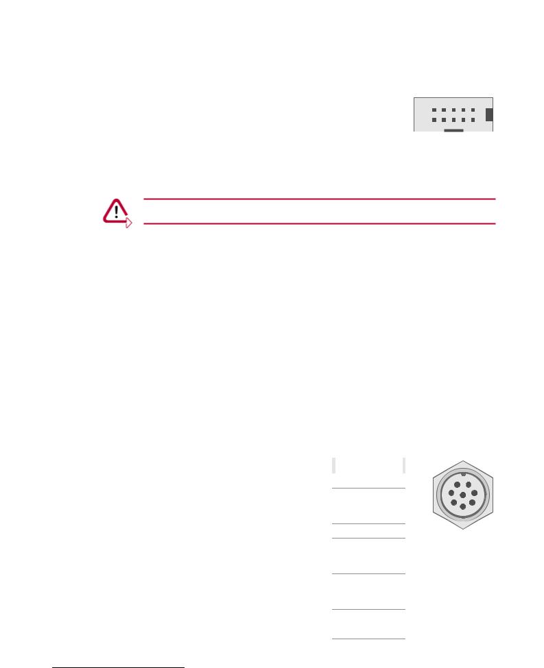
Binder connector |
The following table shows the pin assignment of the 8-pin Binder connector: |
|
|
|
||||||||||
|
|
|
|
|
|
|
|
|
|
|
|
|
||
|
Pin |
|
|
Assignment |
|
|
Software Port2 |
|
|
|
|
|
||
|
1 |
|
Output voltage 5 V (max. 35 mA) |
- |
|
7 |
8 |
1 |
|
|||||
|
2 |
|
|
Trigger In (TTL 5 V, low active) |
3 |
|
6 |
2 |
|
|||||
|
|
|
|
|
|
|||||||||
|
|
|
|
VHmin: |
3.0 |
V / VHmax: |
5.5 V |
|
|
|
5 |
|
3 |
|
|
|
|
|
|
|
|
4 |
|
|
|||||
|
|
|
|
VLmin: |
0.0 |
V / VLmax: |
0.7 V |
|
|
|
|
|
|
|
|
|
|
|
|
|
|
|
|
|
|
||||
|
3 |
|
Trigger Out (TTL 5 V, low active) |
0 |
|
|
|
|
|
|||||
|
4 |
|
|
Trigger In/Out (5 V, low active) |
1 |
|
|
|
|
|
||||
|
|
|
|
VHmin: |
3.0 |
V / VHmax: |
5.5 V |
|
|
|
|
|
|
|
|
|
|
|
VLmin: |
0.0 |
V / VLmax: |
0.7 V |
|
|
|
|
|
|
|
|
5 |
|
|
Trigger In/Out (5 V, low active) |
2 |
|
|
|
|
|
||||
|
|
|
|
VHmin: |
3.0 |
V / VHmax: |
5.5 V |
|
|
|
|
|
|
|
|
|
|
|
VLmin: |
0.0 |
V / VLmax: |
0.7 V |
|
|
|
|
|
|
|
|
6 |
|
Reserved. Do not connect. |
- |
|
|
|
|
|
|||||
|
|
|
|
|
|
|
|
|
|
|||||
|
7 |
|
Reserved. Do not connect. |
- |
|
|
|
|
|
|||||
|
8 |
|
|
GND |
|
|
|
- |
|
|
|
|
|
|
2 Used by Vector software, e. g. in CANoe
© Vector Informatik GmbH |
Version 2.0 |
- 13 - |

FlexRay Interface Family |
Manual |
|
|
2.7.2 LED Display
FlexRay
A, B and Sync
Rx, Tx,
sync and power
The VN3600 has four LEDs with the following meanings:
¼FlexRay A
Lights up, when data is received or transmitted on channel A.
¼FlexRay B
Lights up, when data is received or transmitted on channel B.
¼Sync
LED for both FlexRay channels. Displays the state of the CC:
- Off |
: Offline. |
- Green |
: Synchronized. |
- Orange |
: Not synchronized. |
- Red |
: Error. |
¼Power
Displays the state of operation:
- Red |
: Error, the device is not ready for operation. |
- Green |
: The device is ready for operation. |
- Orange (blinking) |
: An automatic FPGA update is executed. |
The first hardware revision of VN3600 has six LEDs with the following meanings:
¼Rx
Lights up, when data is received.
LED for both FlexRay channels available.
¼Tx
Lights up, when data is transmitted.
LED for both FlexRay channels available.
¼Sync
LED for both FlexRay channels. Displays the state of the CC:
- Off |
: Offline. |
- Green |
: Synchronized. |
- Orange |
: Not synchronized. |
- Red |
: Error. |
¼Power
Displays the state of operation:
- Red |
: Error, the device is not ready for operation. |
- Green |
: The device is ready for operation. |
- Orange (blinking) |
: An automatic FPGA update is executed. |
- 14 - |
Version 2.0 |
© Vector Informatik GmbH |
Manual |
FlexRay Interface Family |
|
|
2.8VN7600
2.8.1 Connectors
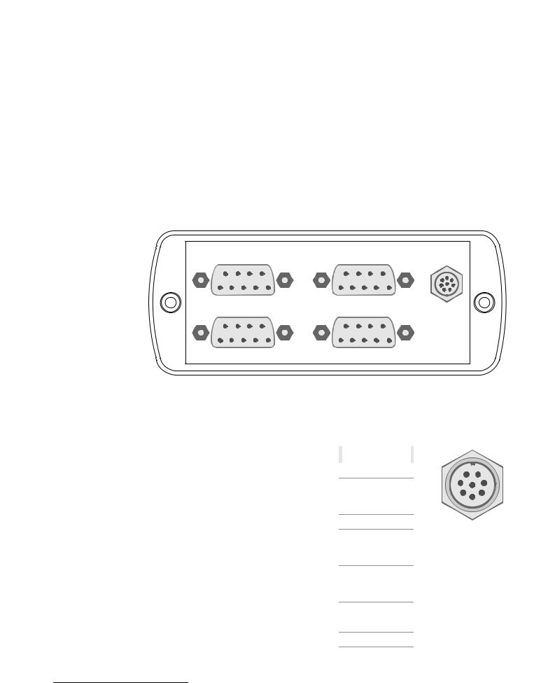
VN7600 (USB)
Alignment
of the connectors
The VN7600 has the following connectors:
¼1x USB 2.0 connector
¼1x D-SUB9 connector for FlexRay (channel A und channel B)
¼3x D-SUB9 connector for CAN
¼1x Binder connector for trigger (8-pin)
¼2x Binder connector for power supply and synchronization between other devices of the FlexRay and XL Family (3-pin)
FlexRay |
CAN 1 |
Trigger |
CAN 2 |
CAN 3 |
|
Main connectors |
The pin assignment of the main connectors can be found in section |
Main Connectors |
|||||||||||
|
on page 10. |
|
|
|
|
|
|
|
|
|
|||
Binder connector |
The following table shows the pin assignment of the 8-pin Binder connector: |
|
|
||||||||||
|
|
|
|
|
|
|
|
|
|
|
|
||
|
Pin |
|
|
Assignment |
|
|
Software Port3 |
|
|
|
|
||
|
1 |
|
Output voltage 5 V (max. 35 mA) |
- |
|
7 |
8 |
1 |
|||||
|
|
|
|
|
|
|
|
|
|
|
6 |
2 |
|
|
2 |
|
|
Trigger In (TTL 5 V, low active) |
3 |
|
|||||||
|
|
|
|
|
|||||||||
|
|
|
|
VHmin: |
3.0 |
V / VHmax: |
5.5 V |
|
|
|
5 |
|
3 |
|
|
|
|
|
|
|
4 |
|
|||||
|
|
|
|
VLmin: |
0.0 |
V / VLmax: |
0.7 V |
|
|
|
|
|
|
|
|
|
|
|
|
|
|
|
|
||||
|
3 |
|
Trigger Out (TTL 5 V, low active) |
0 |
|
|
|
|
|||||
|
4 |
|
Trigger In/Out (5 V, low active) |
1 |
|
|
|
|
|||||
|
|
|
VHmin: |
3.0 |
V / VHmax: |
5.5 V |
|
|
|
|
|
|
|
|
|
|
|
VLmin: |
0.0 |
V / VLmax: |
0.7 V |
|
|
|
|
|
|
|
5 |
|
|
Trigger In/Out (5 V, low active) |
2 |
|
|
|
|
||||
|
|
|
|
VHmin: |
3.0 |
V / VHmax: |
5.5 V |
|
|
|
|
|
|
|
|
|
|
VLmin: |
0.0 |
V / VLmax: |
0.7 V |
|
|
|
|
|
|
|
6 |
|
Reserved. Do not connect. |
- |
|
|
|
|
|||||
|
7 |
|
Reserved. Do not connect. |
- |
|
|
|
|
|||||
|
|
|
|
|
|
|
|
|
|
|
|
|
|
|
8 |
|
|
GND |
|
|
|
- |
|
|
|
|
|
3 Used by Vector software, e. g. in CANoe
© Vector Informatik GmbH |
Version 2.0 |
- 15 - |

FlexRay Interface Family |
Manual |
|
|
D-SUB9 connector |
The VN7600 has three CAN channels through D-SUB9 connectors (male). The con- |
|
nection to the CAN bus is done by transceivers, which are available as plug-in boards |
|
(Piggybacks). The pin assignment of a CAN channel depends on the inserted CAN- |
|
piggy. Further information can be found in the accessories manual on the Driver |
|
Disk: \Documentation\ XL_Family_Accessories.pdf |
2.8.2 LED Display
FlexRay
A, B and Sync
The VN7600 has four LEDs with the following meanings:
¼FlexRay A
Lights up, when data is received or transmitted on channel A.
¼FlexRay B
Lights up, when data is received or transmitted on channel B.
¼Sync
LED for both FlexRay channels available, which displays the state of the CC:
- Off |
: Offline. |
- Green |
: Synchronized. |
- Orange |
: Not synchronized. |
- Red |
: Error. |
¼CAN 1, 2 and 3
Lights up, when data is received or transmitted.
¼Power
Displays the state of operation:
- Red |
: Error, the device is not ready for operation. |
- Green |
: The device is ready for operation. |
- Orange (blinking) |
: An automatic FPGA update is executed. |
- 16 - |
Version 2.0 |
© Vector Informatik GmbH |
Loading...