


VC-EVCC-P
Technical Reference
Version 2.2.0
Authors Vector Informatik GmbH
Status Released

Technical Reference VC-EVCC-P
Document Information
History
|
Author |
|
Date |
|
Version |
|
Remarks |
|
|
|
|
||||
|
ssm |
2020-07-07 |
1.0.1 |
|
Change Authors’ information |
||
|
|
|
|
|
|
|
Add Document information |
|
|
|
|
|
|
||
|
ssm |
2020-07-15 |
1.0.2 |
|
Chapter 1: Update graphic |
||
|
|
|
|
|
|
|
Chapter 2: Update System Overview |
|
|
|
|
|
|
||
|
vml/ssm |
2020-08-04 |
1.1.0 |
|
Chapter “Delivery Content” added |
||
|
|
|
|
|
|
||
|
ssm |
2020-08-27 |
1.2.0 |
|
Chapter “Industrialization” added |
||
|
|
|
|
|
|
||
|
dim |
2020-09-24 |
2.0.0 |
|
Updated for SW release 3.0.0: |
||
|
|
|
|
|
|
|
Chapter 2 “System Architecture” updated (RMP architecture |
|
|
|
|
|
|
|
added) |
|
|
|
|
|
|
|
Chapter 4.14 “Charging Arbitration” added |
|
|
|
|
|
|
||
|
dim |
2020-11-24 |
2.0.1 |
|
Chapter 3.2: Connector description updated |
||
|
|
|
|
|
|
||
|
ssm |
2021-02-03 |
2.1.0 |
|
Chapter 7.5 “Quality Documents” added |
||
|
|
|
|
|
|
||
|
dim |
2021-03-31 |
2.2.0 |
|
Chapter 4.8 Remark about HSOUT added |
||
|
|
|
|
|
|
|
|
Reference Documents
|
No. |
|
|
Source |
|
|
Title |
|
|
[1] |
|
|
OppCharge |
|
Network and application protocol specification for Siemens – Volvo |
|
|||
|
|
|
|
|
|
|
OppCharge implementation, Version 1.3.0 |
|
|
[2] |
|
|
Vector |
|
TechnicalReference_CAN-WiFi-GW |
|
|||
[3] |
|
|
DIN |
|
DIN 70121:2014-12 |
|
|||
[4] |
|
|
DIN |
|
DIN EN 61851-23 - Konduktive Ladesysteme für Elektrofahrzeuge |
|
|||
|
|
|
|
|
|
|
- Teil 23 Gleichstromladestationen für Elektrofahrzeuge (IEC 61851- |
|
|
|
|
|
|
|
|
23:2014) |
|
|
|
[5] |
|
|
DIN |
|
DIN EN 61851-23 Berichtigung 1 - Konduktive Ladesysteme für |
|
|||
|
|
|
|
|
|
|
Elektrofahrzeuge - Teil 23 Gleichstromladestationen für |
|
|
|
|
|
|
|
|
|
Elektrofahrzeuge (IEC 61851-23:2014/COR1:2016) |
|
|
[6] |
|
|
Vector |
|
User Manual |
|
|||
[7] |
|
|
ISO |
|
ISO 15118-2:2014(E) |
|
|||
|
|
|
|
|
|
|
|
|
|
© 2021 Vector Informatik GmbH |
Version 2.2.0 |
2 |
|
based on template version 6.0.2 |
|

Technical Reference VC-EVCC-P
Safety Instructions
Caution
To avoid personal injuries and damage to property you have to read and understand the following safety instructions and hazard warnings prior to installation and use of this ECU. Keep this documentation always near the ECU.
Proper Use and Intended Purpose
Caution
The ECU may only be operated according to the instructions and descriptions of this manual. The ECU is exclusively designed for use by skilled personnel as its operation may result in serious personal injuries and damage to property. Therefore, only those persons may operate the ECU who have understood the possible effects of the actions which may be caused by the ECU. Users have to be specifically trained in the handling (e.g. calibration) with the ECU, the applied embedded software and the system intended to be influenced. Users must have sufficient experience in using the ECU safely.
Hazard Warnings
Caution
The ECU may control and/or otherwise influence the behavior of control systems and electronic control units. Serious hazards for life, body and property may arise, in particular without limitation, by interventions in safety relevant systems (e.g. by deactivation or otherwise manipulating the engine management, steering, airbag and/or braking system) and/or if the ECU is operated in public areas (public traffic). Therefore, you must always ensure that the ECU is used in a safe manner. This includes inter alia the ability to put the system in which the ECU is used into a safe state at any time (e.g. by “emergency shutdown”), in particular without limitation in the event of errors or hazards. Furthermore, all technical safety and public law directives which are relevant for the system in which the ECU is used must apply. Provided that serious hazards for life, body and property may occur and before the use in public areas the system in which the ECU is used must be tested according to recognized rules of engineering in a non-public area.
© 2021 Vector Informatik GmbH |
Version 2.2.0 |
3 |
|
based on template version 6.0.2 |
|

|
|
|
|
Technical Reference VC-EVCC-P |
Contents |
|
|
|
|
1 |
General .......................................................................................................................... |
|
7 |
|
2 |
System Architecture ..................................................................................................... |
8 |
||
|
2.1 |
OppCharge Architecture..................................................................................... |
8 |
|
|
2.2 |
Roof-Mounted Pantograph Architecture ............................................................. |
9 |
|
|
2.3 |
Supported Peripherals ....................................................................................... |
9 |
|
3 |
ECU.............................................................................................................................. |
|
|
10 |
|
3.1 |
ECU Overview ................................................................................................. |
10 |
|
|
3.2 |
Key ECU Characteristics.................................................................................. |
11 |
|
4 |
Functional Overview................................................................................................... |
12 |
||
|
4.1 |
CP Communication .......................................................................................... |
12 |
|
|
4.2 |
WiFi Communication (OppCharge only)........................................................... |
12 |
|
|
4.3 |
Power Line Communication ............................................................................. |
13 |
|
|
|
4.3.1 |
Low Level communication with EVSE .............................................. |
13 |
|
|
4.3.2 |
DC Charging with High Level Communication.................................. |
13 |
|
4.4 |
Stop Button ...................................................................................................... |
14 |
|
|
4.5 |
StopCharge CAN Signal .................................................................................. |
14 |
|
|
4.6 |
Clamp 15 Signal Input...................................................................................... |
14 |
|
|
4.7 |
Status LEDs..................................................................................................... |
14 |
|
|
4.8 |
High Side Outputs............................................................................................ |
14 |
|
|
4.9 |
Reprogramming of the ECU Software .............................................................. |
15 |
|
|
4.10 |
Self-Diagnostics ............................................................................................... |
15 |
|
|
4.11 |
ECU State Handling......................................................................................... |
15 |
|
|
4.12 |
Vehicle Immobilization (OppCharge only) ........................................................ |
16 |
|
|
4.13 |
Configuration of Software................................................................................. |
16 |
|
|
4.14 |
Charging Arbitration ......................................................................................... |
16 |
|
5 |
Qualification................................................................................................................ |
|
17 |
|
|
5.1 |
Configuration ................................................................................................... |
17 |
|
|
5.2 |
Electrical Tests ................................................................................................. |
17 |
|
|
5.3 |
EMC Test ......................................................................................................... |
|
18 |
|
5.4 |
Climatic Tests................................................................................................... |
18 |
|
|
5.5 |
Mechanical Tests ............................................................................................. |
19 |
|
|
5.6 |
Life Tests.......................................................................................................... |
|
19 |
|
5.7 |
Chemical Tests................................................................................................. |
19 |
|
6 |
Industrialization .......................................................................................................... |
|
21 |
|
© 2021 Vector Informatik GmbH |
Version 2.2.0 |
4 |
|
based on template version 6.0.2 |
|

|
|
|
Technical Reference VC-EVCC-P |
7 |
Delivery Content ......................................................................................................... |
22 |
|
|
7.1 |
ECU ................................................................................................................. |
22 |
|
7.2 |
Packaging ........................................................................................................ |
22 |
|
7.3 |
Software .......................................................................................................... |
23 |
|
7.4 |
Technical Documents....................................................................................... |
23 |
|
7.5 |
Quality Documents........................................................................................... |
23 |
8 |
Glossary and Abbreviations ...................................................................................... |
25 |
|
© 2021 Vector Informatik GmbH |
Version 2.2.0 |
5 |
|
based on template version 6.0.2 |
|

|
Technical Reference VC-EVCC-P |
|
Illustrations |
|
|
Figure 1-1 |
VC-EVCC-P................................................................................................ |
7 |
Figure 2-1 |
System Overview OppCharge (Inverted Pantograph) ................................. |
8 |
Figure 2-2 |
System Overview Roof-Mounted Pantograph (RMP) .................................. |
9 |
Figure 3-1 |
VC-EVCC-P Interfaces ............................................................................. |
10 |
Figure 7-1 |
VC-EVCC-P packed in Cardboard Package ............................................. |
22 |
Tables |
|
|
Table 1-1 |
Delivery Content ......................................................................................... |
7 |
Table 3-1 |
VC-EVCC-P Key Characteristics .............................................................. |
11 |
Table 4-1 |
Low Level Communication – Duty Cycle of CP PWM ............................... |
13 |
Table 5-1 |
Qualification Configuration........................................................................ |
17 |
© 2021 Vector Informatik GmbH |
Version 2.2.0 |
6 |
|
based on template version 6.0.2 |
|
Technical Reference VC-EVCC-P
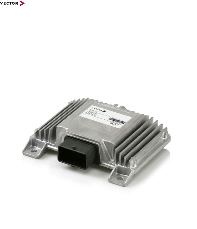
1 General
The Vector Controller - Electric Vehicle Communication Controller for Pantograph (VC- EVCC-P) is a generic ECU for 24V environments.
It realizes electrical charging according to OppCharge V1.3.0 (see [1]) in combination with an additional CAN-WiFi-Gateway for communication with the charging infrastructure.
In addition, charging with a roof-mounted pantograph is supported.
The hardware is the VC36PLC-24 with an integrated flash bootloader. VC-EVCC-P includes a modern MICROSAR stack with all relevant application modules to realize electrical charging communication.
Figure 1-1 VC-EVCC-P
The following parts are included in the delivery:
|
|
Part |
|
Description |
|
|
|
||
|
|
VC-EVCC-P |
|
ECU with integrated software |
|
|
|
|
|
|
|
Documentation |
|
Customer receives a Technical Reference (this |
|
|
|
|
document) as well as a User Manual and |
|
|
|
|
Charging Sequence Diagrams |
|
|
|
|
|
|
|
Remaining Bus Simulation |
|
CANoe bus simulation for the VC-EVCC-P for |
|
|
|
|
bus test and evaluation purposes |
|
|
|
|
CAN database description (dbc) |
|
|
|
|
Diagnostic description file (cdd) |
Table 1-1 Delivery Content |
|
|
||
© 2021 Vector Informatik GmbH |
Version 2.2.0 |
7 |
|
based on template version 6.0.2 |
|

Technical Reference VC-EVCC-P
2 System Architecture
The VC-EVCC-P is designed to be integrated into the vehicle with one of the following system architectures.
2.1OppCharge Architecture
Figure 2-1 System Overview OppCharge (Inverted Pantograph)
Red components are in focus of VC-EVCC-P system context and are provided by Vector. Non-red components, e.g. CAN-I/O Interface, have to be supplied alternatively in case Temperature or Heater control shall be implemented.
© 2021 Vector Informatik GmbH |
Version 2.2.0 |
8 |
|
based on template version 6.0.2 |
|
 Loading...