

Page 1
SERIES-X
I F GB D
XDW
D Bedienungsanleitung
GB Instruction Manual
F Manuel d‘ Installation et d‘ Utilisation
I Manuale d‘ Installazione e Funzionamento
Page 2

X1DW VDO CYCLECOMPUTING2
D GB F I
I F GB D
www.vdocyclecomputing.com X1DW 3
Vorwort
Herzlichen Glückwunsch.
Mit Ihrer Wahl für einen VDO Computer haben Sie sich für ein technisch sehr hochwertiges Gerät entschieden.
Um das Potenzial des Computers optimal ausnutzen zu können, empfehlen wir Ihnen, diese Anleitung
sorgfältig zu lesen. Sie erhalten alle Hinweise zur Bedienung sowie viele weitere nützliche Tips.
Wir wünschen Ihnen viel Freude beim Fahren mit Ihrem VDO Cyclecomputer.
Cycle Parts GmbH
Verpackungsinhalt
Bitte prüfen Sie zunächst die Vollständigkeit dieser Verpackung:
1 VDO Computer
Batterie eingebaut
1 Geschwindigkeits-Sender
Batterie eingebaut
1 Universal-Lenkerhalterung
Inhaltsverzeichnis
1. Display 4
2. Bedienung 6
3. Funktionen 7
3.1 Informations-Funktionen 7
3.2 Trittfrequenz-Option 8
4. Installation 8
4.1 Montage von Sender, Magnet
und Lenkerhalterung 8
4.2 Erstes Einschalten des Computers 9
4.3 Batterieeinbau in den Computer 9
4.4 Einsetzen des Computers
in die Lenkerhalterung 10
4.5 Sender Pairing 10
5. Grundeinstellungen 11
5.1 Sprache einstellen 11
5.2 Einstellen und Messen
der Radgröße 11
5.2.1 Einstellen über Reifentabelle 11
5.2.2 Einstellen über Radumfang 13
5.3 Einstellen Uhr 14
5.4 Einstellen Gesamtkilometer 15
5.5 Umschalten von Rad 1 auf Rad 2 15
5.6 Service-Intervall-Anzeige 16
5.7 Sleep-Modus 17
5.8 Reset-Funktionen 18
6. Garantiebedingung 19
7. Fehlerbehebung 20
8. Technische Spezifikationen 21
1 Unterleg Gummi
für Sender
1 Speichenmagnet
(Clip-Magnet)
Kabelbinder
zur Montage der Halterung
und des Senders
„>>> P02“ Verweise am Anfang eines Kapitels
verweisen auf das entsprechende Bild im
Picturebook!
Page 3
X1DW VDO CYCLECOMPUTING4
D GB F I
I F GB D
www.vdocyclecomputing.com X1DW 5
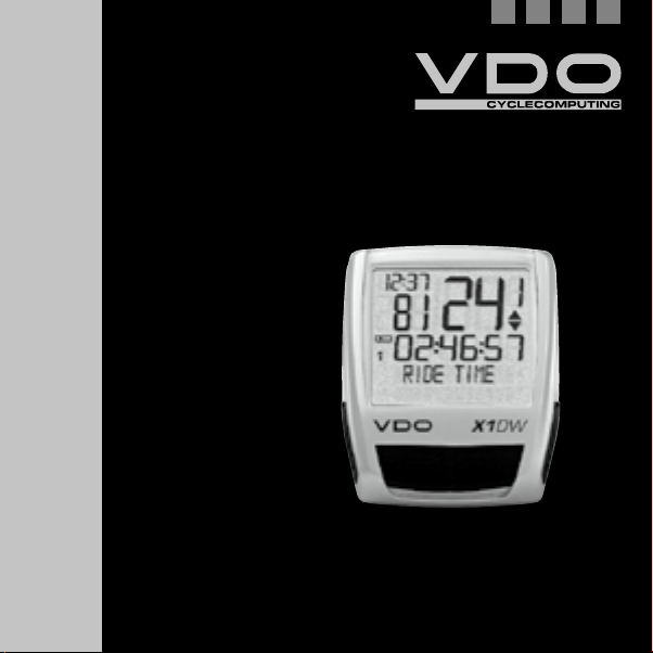
1. Display
Das Di splay kann ma n in
5 Segme nte glieder n:
Segme nt 1
Zeigt im mer die
aktu elle Uhrzei t.
Segme nt 2
Zeigt die aktuelle Trittfrequenz,
wenn der Trittfrequenz-Sender
installiert ist (Option).
Zusät zlich finde n Sie im
Display Indikator-Elemente.
Die Beschreibung der einzelnen
Indikatoren finden Sie auf der
rechten Seite.
Segme nt 3
Zeigt die aktuelle
Geschwindigkeit.
Segme nt 4
Zeigt den Wert der von
Ihnen gewählten AnzeigeFunktion/Information.
Segme nt 5
Zeigt in der oberen Zeile
(Info-Zeile) die Bezeichnung
der gewählten Funktion.
In der zweiten Zeile (MenüZeile) wird angezeigt,
B
ob es weitere Informati-
onen gibt „MEHR“
B
ob es eine weitere
Auswahlmöglichkeit
gibt „AUSWAHL“
Serv ice Indikat or
Zeigt an, dass Ihr Fahrrad zum Service sollte.
Das Service-Intervall können Sie für Rad 1 und Rad 2
individuell festlegen.
Indika tor Rad 1/ Rad 2
Der Computer kann mit zwei verschiedenen Einstellungen für 2 Fahrräder arbeiten. Der Indikator
zeigt an, welches der beiden Fahrräder Sie zur
Nutzung ausgewählt haben. Die Gesamtkilometer werden entsprechend für Rad 1 und für Rad 2
getrennt gezählt und gespeichert.
Me sseinheit ( KMH oder MPH)
Der Computer kann sowohl KMH als auch MPH
anzeigen. Strecken werden entsprechend in Kilometer oder Meilen angezeigt. Der Indikator zeigt
die gewählte Messeinheit an.
Abweic hungsindi kator Gesc hwindigkei t
(akt uell) zu Gesc hwindigkei t (Schnitt)
Der Computer vergleicht die aktuelle Geschwindigkeit mit der Durchschnittsgeschwindigkeit.
Der Indikator zeigt an
B
ob die aktuelle Geschwindigkeit über dem
Durchschnitt liegt (+1 km/h)
B
unter dem Durchschnitt liegt (-1 km/h)
B
oder dem Durchschnitt entspricht
(Toleranz +/- 1 km/h)
Menus teuerungs indikato r
Wenn ein Untermenu aufgerufen wurde, blinken
diese Indikatoren und zeigen an, dass es noch
weitere Auswahlmöglichkeiten gibt oder der Computer auf eine Eingabe wartet (Einstell-Modus).
Page 4
X1DW VDO CYCLECOMPUTING6
D GB F I
I F GB D
www.vdocyclecomputing.com X1DW 7
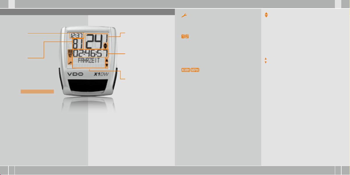
2. Bedienung
Für die einfache Bedienung Ihres Computers haben
wir das EMC = Easy Menu Control System entwickelt.
Das EMC erleichtert die Bedienung des Computers
über eine Volltext-Menüführung wie sie
bei den meisten Handys verwendet wird.
C = CLEAR
DOWN
C
= CLEAR
Im Funktions-Modus:
B
Vom Untermenü eine Menüebene
zurück springen.
Im Einst ell-Mod us:
B
Zurückspringen
zu Funktions-Modus.
B
Eine Eingabe korrigieren.
B
Eine Ziffer zurückspringen.
= DOWN
Im Funkt ions-Mo dus:
B
Innerhalb der Funktionen
abwärts blättern.
Im Einst ell-Mod us:
B
Innerhalb der Einstell-Modi
abwärts blättern.
B
Eine Ziffer verringern.
Menü-Indikatoren im Display zeigen durch Blinken
an, dass es weitere Auswahlmöglichkeiten gibt. Im
Funktions-Modus und im Einstell-Modus erfolgt
die Bedienung über die 4 Tasten.
M = MENU
UP
FUNKTION 3
FUNKTION 4
FUNKTION 5
FUNKTION 6
M
= MENU
Im Funkt ions-Mo dus:
B
Verfügbares Untermenü aufrufen.
B
Auswahl bestätigen.
Sie erkennen ein Untermenü durch
die blinkenden Menü-Indikatoren.
Im Einst ell-Mod us:
B
Eine Einstellung auswählen.
B
Eine gemachte Einstellung bestätigen.
B
Eine getroffene Auswahl bestätigen.
= UP
Im Funkt ions-Mo dus:
B
Innerhalb der Funktionen
aufwärts blättern.
Im Einst ell-Mod us:
B
Innerhalb der Einstell-Modi
aufwärts blättern.
B
Eine Ziffer erhöhen.
3. Funktionen
3.1 Informations-Funktionen
TAGESTOUR
Zeigt die Strecke der aktuellen Tour seit dem letzten
Reset. Maximalwert 999,99 km.
Bei Überschreiten des Maximalwertes beginnt der
Zähler wieder bei Null. Gleichzeitig werden die
Werte für Fahrzeit und Durchschnittsgeschwindigkeit auf Null zurückgesetzt.
TAGESTOUR/MEHR
MEHR zeigt an, dass es zum Hauptmenu TAGESTOUR ein Untermenu gibt. Das Untermenu öffnen
Sie mit M. Im Untermenu finden Sie:
B
Gesamtkilometer RAD 1 bis max. 99.999 km
B
Gesamtkilometer RAD 2 bis max. 99.999 km
B
Totalkilometer Summe für Rad 1 + Rad 2
bis max. 199.999 km
Das Untermenu verlassen Sie wieder mit C.
FAHRZE IT
Zeigt die Fahrzeit der aktuellen Tagestour seit
dem letzten Reset. Maximal 23:59:59 HH:MM:SS.
Bei überschreiten des Maximalwertes beginnt die
Fahrzeit-Messung bei Null. Gleichzeitig werden
Tagestour und Durchschnittsgeschwindigkeit auf
Null zurückgestellt.
DSCHN GS CHW
Zeigt die Durchschnittsgeschwindigkeit, berechnet
aus Tagestour und Fahrzeit, seit dem letzten Reset.
Genauigkeit: 2 Kommastellen.
Die Durchschnittsgeschwindigkeit wird neu berechnet, wenn die Tagestour oder die Fahrzeit den
Maximalwert übersteigt.
MAX G SCHW
Zeigt die Maximalgeschwindigkeit auf der aktuellen
Tour seit dem letzten Reset. Genauigkeit: 2 Kommastellen.
Page 5

X1DW VDO CYCLECOMPUTING8
D GB F I
I F GB D
www.vdocyclecomputing.com X1DW 9
3.2 Trittfrequenz-Option
Das Trittfrequenz-Menü steht nur zur Verfügung,
wenn:
B
der Trittfrequenz-Sender installiert ist.
B
der Sender beim Pairing installiert wurde.
Nach dem Pairing des Trittfrequenz-Senders wird
im Segment 2 des Displays die aktuelle Trittfrequenz angezeigt. Im Funktions-Modus ist über die
-Tasten das Menü TRITT FREQ/MEHR anwählbar.
Bestätigen mit M öffnet das Menü und Sie haben
Zugriff auf die Informationen.
Mit kommen Sie zu:
B
DSCHN TRITT (Durchschnitt-Trittfrequenz).
B
MAX TRITT (Maximale Trittfrequenz).
Mit dem RESET der Tourdaten werden auch die
Trittfrequenz-Daten auf Null zurückgestellt.
4 Installation
4.1 Montage von Sender, Magnet und Lenkerhalterung >>> P01
Beginnen Sie mit der Montage von Sender und
Magnet.
ACHTUNG: Der Abstand des Senders vom Computer
am Lenker sollte nicht über 60 cm liegen (Funkreichweite).
step 1 Legen Sie das Unterleg-Gummi unter den
Sender. Montieren Sie den Sender auf der Gabelseite, an der Sie später den Computer am Lenker
montieren wollen (rechts oder links) mit beiliegendem Kabelbinder (zunächst lose, noch nicht
festziehen).
ACHTUNG: Die Sensor-Markierung auf dem Sender
muss dab ei zu den Speich en zeigen.
Der Sender kann je nach Platzverhältnissen vorne
auf die Gabel, innen an der Gabel oder hinten an
der Gabel, montiert werden. >>> P04
step 2 Speichenmagnet um eine Außen-Speiche
legen. Der silberne Magnetkern zeigt dabei zum
Sender. Magnet an der Sensor-Markierung auf
dem Sender mit etwa 1 – 5 mm Abstand ausrichten.
step 3 Sender und Magnet endgültig ausrichten
und fixieren: Kabelbinder festziehen und Magnet
kräftig zudrücken.
step 4 Entscheiden ob Lenker-oder Vorbau-Montage, entsprechend den Fuß der Lenkerhalterung
um 90° drehen. Dazu die Schrauben in der Halterung lösen, Fuß herausnehmen und um 90° drehen,
einsetzen und Schrauben wieder festdrehen.
ACHTUNG: Schr auben nicht üb erdrehen.
step 5 Kabelbinder durch die Schlitze in derLenkerhalterung führen, um den Lenker oder den Vorbau
legen und anziehen (noch nicht festziehen).
step 6 Bei Lenkermontage: Neigungswinkel des
Computers ausrichten, um optimale Ablesbarkeit
zu erreichen. Kabelbinder jetzt festziehen.
Überstehende Enden mit Zange abknipsen.
4.2 Erstes Einschalten des Computers >>> P02, Display siehe Kapitel 5.1
Aufwe cken aus Vers andmodus
Der Computer wird mit eingebauter Batterie ausgeliefert. Um den Batterieverbrauch zu reduzieren,
wird der Computer in einen Versandmodus versetzt. Das Display ist leer (keine Anzeige).
Zum Aufwecken aus dem Versandmodus drücken
Sie die -Taste gleichzeitig für einige Sekunden. Der Computer ist jetzt betriebsbereit und
meldet sich mit der Einstellung der Sprache zurück.
Siehe hie rzu auch Kap itel 5.1
4.3 Batterieeinbau in den Computer >>> P05
Ihr VDO Computer wird mit einer 3V Batterie
(Type 2032) geliefert. Die Bat terie ist im Li efer-
statu s bereits e ingebaut . Zum Batteriewechsel
gehen Sie folgendermaßen vor:
step 1 Legen Sie die Batterie mit dem +Pol nach
oben in das Computergehäuse ein.
step 2 Achten Sie darauf, dass sich die Batterie
nicht verkantet.
step 3 Beachten Sie, dass die Gummidichtung
glatt auf dem Batteriefachdeckel aufliegt.
step 4 Setzen Sie den Batteriefachdeckel in die
Öffnung ein und drehen Sie ihn mit einem Geldstück
nach rechts bis zum Anschlag fest
(ca. ⅓ Umdrehung).
TIPP zum B atteriewe chsel: VDO empfie hlt einen
jährli chen Batter iewechsel . Kaufen Sie re chtzeiti g
eine neu e Batterie, um e ine einwandfr eie Funktion der Fu nkübertra gung sicher zustellen. Be im
Batte riewechsel w erden alle Eins tellungen und
die gefa hrenen Gesa mtkilometer ge speicher t.
Page 6
X1DW VDO CYCLECOMPUTING10
D GB F I
I F GB D
www.vdocyclecomputing.com X1DW 11
4.4 Einsetzen des Computers in die Lenkerhalterung >>> P06
Das VDO Twist-Click-System verbindet den Computer
sicher mit der Lenkerhalterung.
step 1 Computer in 10 Uhr-Position in die Halterung einsetzen.
step 2 Computer nach rechts auf 12-Uhr-Position drehen „twist“ und in das Haltesystem einrasten „click“.
step 3 Zum Herausnehmen den Computer nach
links drehen (dabei nicht drücken oder ziehen).
Gedankenstütze: Rein nach Rechts, Los nach Links
4.5 Sender Pairing
Die Geschwindigkeits- und Trittfrequenzsignale
(Option: Artikel Nr. 7702) werden digital und codiert
an Ihren Computer übertragen. Diese Technik ist
weniger störanfällig als analoge Übertragung.
Dadurch kommt es beim Fahren in der Gruppe
nicht zu Datenüberlagerungen (kein Cross Talk).
Damit der Computer die digitalen Codierungen der
Sender erlernt, muss ein Pairing gemacht werden:
step 1 Setzen Sie den Computer in die Lenkerhalterung. Die Anzeige für die Geschwindigkeit und
für die Trittfrequenz blinkt jetzt. Das Blinken zeigt
an, dass der Computer seine Sender sucht.
step 2 Drehen Sie jetzt das Vorderrad, oder fahren
Sie einfach los und der Computer erlernt die
digitalen Codierungen (Pairing). Sobald das Pairing erfolgreich war, werden Geschwindigkeit und
Trittfrequenz im Display angezeigt.
ACHTUN G: Die Pairing zeit beträg t 5 Minuten.
Wenn Sie in di esen 5 Minuten nic ht losfahren ,
findet kei n Pairing stat t. Geschwindi gkeit und
Trittfr equenz werd en nicht angeze igt. Das Pa iring muss d ann wiederho lt werden:
B
Den Computer e rneut in die Len kerhalterung
einset zen oder
B
die Tastenkomb ination C + M drücken .
5. Grundeinstellungen
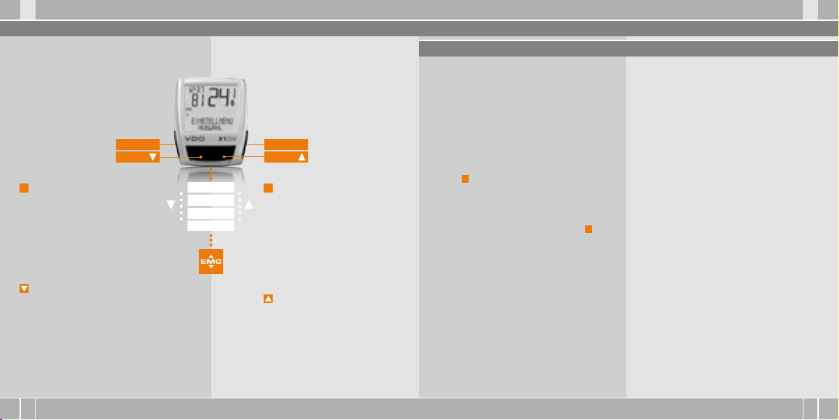
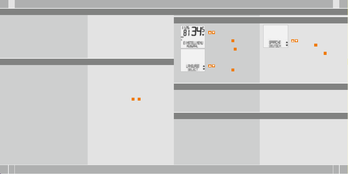
5.1 Sprache einstellen
Gehen Sie mit den
-Tasten zu
EINSTELLMENU/AUSWAHL.
Bestätigen mit
Sie befinden sich jetzt im Einstell-Modus (mit
den kommen Sie zurück in den
Funktions-Modus).
zu LANGUAGE SELECT.
Bestätigen mit M.
M
.
C
– 3 Sekun-
5.2 Einstellen und Messen der Radgröße
Damit Ihr VDO Computer korrekt messen kann,
müssen Sie die Radgröße (Radabrollumfang) Ihres
Rades einstellen.
5.2.1 Einstellen über Reifentabelle
In der Reifentabelle sind die gängigen Reifentypen
aufgeführt. Wenn Ihr Reifentyp nicht aufgeführt
ist, empfehlen wir die manuelle Eingabe der Radgröße. Die in der Tabelle genannten Werte sind
Näherungswerte.
zu SPRACHE DEUTSCH.
Bestätigen mit M.
DEUTSCH AUSWAHL OK? Bestätigen mit M.
Rückmeldung des Computers: SPRACHE AUSW
FERTIG. Der Computer kehrt automatisch zum
Ausgangsmenu EINSTELLMENU/AUSWAHL zurück.
Hier gibt es 2 Möglichkeiten:
Diese Werte weichen je nach Reifen-Marke,
Reifenhöhe und Reifenprofil ab. Es kann daher
auch zu Abweichungen der gemessenen Strecke
und der angezeigten Geschwindigkeit kommen.
Page 7
X1DW VDO CYCLECOMPUTING12
D GB F I
I F GB D
www.vdocyclecomputing.com X1DW 13
16 x 1,7 5 1272 50,1
20 x 1,7 5 1590 62,6
24 x 1 ⅜ 1948 76,7
24 x 1, 75 1907 75,1
26 x 1 1973 77,7
26 x 1,5 2026 79,8
26 x 1,6 2051 80,7
26 x 1,7 5 2070 81,5
26 x 1,9 2089 82,2
26 x 2,0 0 2114 83,2
26 x 2, 125 2133 84,0
26 x 1 ⅜ 2105 82,9
26 x ¾ 1954 76,9
27 x 1 ¼ 2199 86,6
28 x 1,5 2224 87,6
28 x 1, 75 2268 89,3
28 x 1 ½ 2265 89,2
28 x 1 ⅜ 2205 86,8
30-622 2149 84,6
32-622 2174 85,6
37-62 2 2205 86,8
40-622 2224 87,6
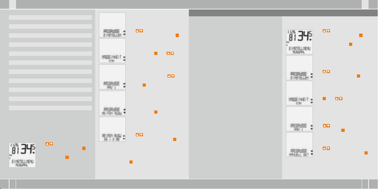
So stel len Sie die Reif engröße üb er Auswahl
des Rei fens ein:
mm-Wert inch-Wert
Mit zu EINSTELLMENU/
AUSWAHL. Bestätigen mit M.
Sie befinden sich jetzt im Einstell-Modus (mit C – 3 Sekunden kommen Sie zurück in den
Funktions-Modus).
Es erscheint die Kontrollabfrage: „Reifengröße“/
AUSWAHL OK? Wenn die angezeigte Reifengröße
mit der von Ihnen gewünschten übereinstimmt,
bestätigen Sie mit M.
Das Display bestätigt RADGRÖSSE/SET FERTIG.
Automatische Rückkehr zu EINSTELLMENU/AUSWAHL.
Mit zu RADGRÖSSE/
EINSTELLEN. Bestätigen mit M.
MASSEINHEIT/KMH.
Bestätigen mit M oder
zum Wechsel zu MPH.
RADGRÖSSE/RAD 1 (mit zur
Einstellung für Rad 2). Bestätigen mit M.
RADGRÖSSE/REIFEN AUSW.
Bestätigen mit M.
REIFEN AUSW./WÄHLEN.
Mit wählen Sie jetzt Ihren
Reifen aus. Bestätigen mit M.
5.2.2 Einstellen über Radumfang >>> P07
Für die manuelle Eingabe der Radgröße müssen Sie
zunächst den Radabrollumfang Ihres Rades messen.
Messe n der Radab rollumfän ge:
step 1 Ventil des Vorderrades genau senkrecht
zum Boden ausrichten.
step 2 Diese Stelle am Boden mit einem Strich
(z.B. Kreide) markieren.
step 3 Das Rad eine Radumdrehung nach vorn
schieben, bis das Ventil erneut senkrecht zum
Boden steht.
step 4 Diese Stelle ebenfalls am Boden markieren.
step 5 Den Abstand zwischen den beiden Markie-
rungen messen. Das ist Ihr Radumfang (=AbrollUmfang).
step 6 Geben Sie den so gemessenen Radumfang
in Ihren VDO-Computer ein.
ACHTUN G: Wenn Sie KMH– Anzeige gewä hlt
haben , müssen Sie den Ra dumfang in mm ein geben (B ei gewählter M PH-Anzei ge geben Sie
den Radum fang in inch ein).
So stel len Sie manue ll die Radgr öße ein:
Mit zu EINSTELLMENU/
AUSWAHL. Bestätigen mit M.
Sie befinden sich jetzt im
Einstell-Modus (mit C –
3 Sekunden kommen Sie
zurück zum Funktions-Modus).
Mit zu RADGRÖSSE/EINSTELLEN. Bestätigen mit M.
MASSEINHEIT/KMH. Bestätigen
mit M oder zum Wechsel
zu MPH.
RADGRÖSSE/ RAD 1
(mit zur Einstellung für Rad 2).
Bestätigen mit M.
Mit zu RADGRÖSSE/
MANUELL SET. Bestätigen mit M.
Page 8
X1DW VDO CYCLECOMPUTING14
D GB F I
I F GB D
www.vdocyclecomputing.com X1DW 15
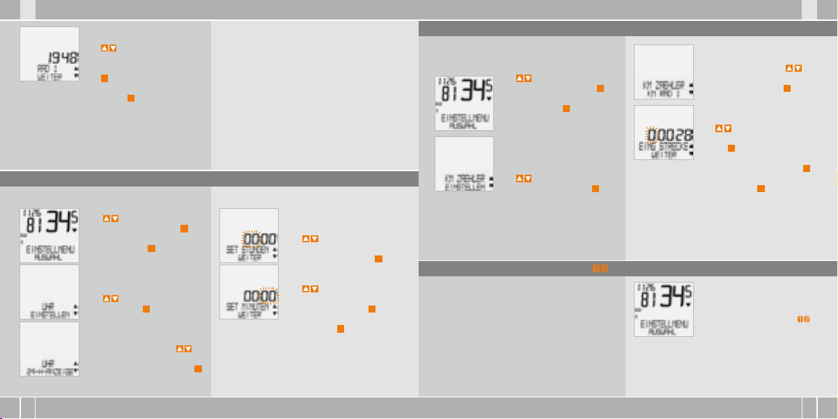
RAD 1 …SET UMFANG/WEITER
Mit stellen Sie jetzt den
gemessenen Radabrollumfang
ein. Bestätigen Sie die Eingabe
mit M.
RAD 1/SET OK? Bestätigen mit M.
Das Display bestätigt: RADGRÖSSE/SET FERTIG
Automatische Rückkehr zu EINSTELLMENU/
AUSWAHL.
Achtung : Die Werksein stellungen bet ragen für
Rad 1 = 215 5 mm und für Rad 2 = 200 0 mm. Wenn
Sie keine R adgrößen eing eben, arbe itet der
Computer m it diesen Werk seinstellunge n. Die so
gemess enen Werte fü r Geschwindigke it, Strecke
etc. könn en deutlich v on den tats ächlichen We rten
abweichen.
5.3 Einstellen Uhr
So stel len Sie die Uhr ei n:
Mit zu EINSTELLMENU/
AUSWAHL Bestätigen mit M.
Sie befinden sich jetzt im Einstell-Modus (mit C – 3 Sekunden kommen Sie zurück zum
Funktions-Modus).
Mit zu UHR/EINSTELLEN
Bestätigen mit M.
UHR/SET OK? Bestätigen Sie mit M.
UHR/24-H-ANZEIGE (mit
können Sie umstellen auf
12-H-Anzeige). Bestätigen mit M.
Das Display bestätigt: UHR SET FERTIG. Automatische Rückkehr zu EINSTELLMENU/AUSWAHL.
UHR…SET STUNDEN/WEITER
Mit stellen Sie die Stunden ein. Bestätigen Sie die
Stundeneinstellung mit M.
UHR…SET MINUTEN/WEITER
Mit stellen Sie die Minuten ein. Bestätigen Sie die Minuten-Einstellung mit M.
5.4 Einstellen Gesamtkilometer
Sie können die Werte der Streckenzähler jederzeit
(z.B. am Ende einer Saison) programmieren.
Mit zu EINSTELLMENU/
AUSWAHL. Bestätigen mit M.
Sie befinden sich jetzt im Einstell-Modus (mit C – 3 Sekunden kommen Sie zurück zum
Funktions-Modus).
Mit zu KM ZÄHLER/EINSTELLEN. Bestätigen mit M.
KM RAD 1/SET OK? Bestätigen mit M.
Das Display bestätigt KM RAD 1 /SET FERTIG.
Automatische Rückkehr zu EINSTELLMENU/
AUSWAHL.
KM ZÄHLER/RAD 1 (mit
kommen Sie zur Einstellung für
RAD 2). Bestätigen mit M.
KM RAD 1… EING STRECKE/WEITER
Die blinkende Ziffer können Sie
mit einstellen. Zum Aufruf
der nächsten Ziffer bestätigen
Sie mit M. Wiederholen Sie die
Schritte, bis die letzte, rechte
Ziffer blinkt. Bestätigen mit M.
5.5 Umschalten von Rad 1 auf Rad 2 >>> P03
Ihr VDO Computer kann an 2 Fahrrädern verwendet
werden. Wenn Sie von Rad 1 auf Rad 2 wechseln,
erkenn t der Compute r den Sender von Rad 2.
Der Computer stellt sich dann automatisch auf
Rad 2 um. Alle Daten werden jetzt für Rad 2 abgespeichert. Wenn Sie den Computer wieder an Rad 1
verwenden, wird Sender 1 erkannt. Der Computer
stellt sich auf Rad 1 um. Die Daten werden jetzt
für Rad 1 abgespeichert.
Hinweis : Der Sender am R ad 2 muss vor Inbe triebn ahme auf Rad 2 eing estellt worde n sein.
>>> P03
Das ausgewählte Rad 1 oder 2
wird im Display unten links ( )
angezeigt.
Page 9
X1DW VDO CYCLECOMPUTING16
D GB F I
I F GB D
www.vdocyclecomputing.com X1DW 17
5.6 Service-Intervall-Anzeige
Die VDO Service-Intervall-Anzeige erinnert Sie daran,
Ihr Rad in der Werkstatt überprüfen zu lassen.
Sie können das Service-Intervall EIN- oder AUSschalten. Sie können individuelle Service-Intervalle
für 2 Räder einstellen. Wenn die eingestellte
Service-Intervall-Strecke gefahren wurde:
B
Blinkt das -Symbol im Display auf.
B
In der Informationszeile erscheint
RAD SERVICE/RAD 1
Jetzt sollten Sie den empfohlenen Radcheck entweder selbst durchführen oder Ihr Rad vom Fachhändler checken lassen.
Drücken Sie eine beliebige Taste. Der Text RAD SERVICE verschwindet wieder. Nach weiteren 50 km
erlischt auch das
das blinkende
Sie dazu das Service-Intervall erneut ein.
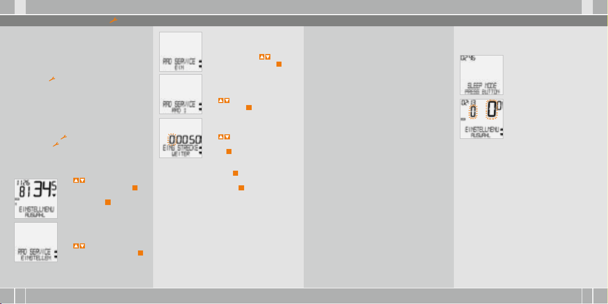
So stel len Sie die Ser vice-I ntervall e ein:
-Symbol wieder. Sie können
-Symbol auch abschalten. Geben
Mit zu EINSTELLMENU/
AUSWAHL. Bestätigen mit
Sie befinden sich jetzt im Einstell-Modus (mit C – 3 Sekunden
kommen Sie zurück zum Funktions-Modus).
Mit zu RADSERVICE/
EINSTELLEN. Bestätigen mit M.
M
.
Wiederholen Sie die Schritte, bis die letzte, rechte
Ziffer blinkt. Bestätigen mit M.
RAD 1/SET OK? Bestätigen mit M.
Das Display bestätigt: RADSERVICE/SET FERTIG.
Automatische Rückkehr zu EINSTELLMENU/
AUSWAHL.
RADSERVICE/EIN (mit schalten
Sie auf AUS). Bestätigen mit M.
RAD SERVICE/RAD 1.
Mit wechseln Sie zu RAD 2.
Bestätigen mit M.
RAD 1…EING STRECKE.
Die blinkende Ziffer können Sie
mit einstellen. Zum Aufruf
der nächsten Ziffer bestätigen
Sie mit M.
5.7 Sleep-Modus
Ihr VDO-Computer ist mit einer zweifachen SleepModus Funktion ausgestattet. Im Sleep-Modus
wird ein Großteil des Displays ausgeschaltet, um
Batterieleistung zu sparen. Uhrzeit und ServiceIntervall Anzeige werden weiter angezeigt.
Der Sleep -Modus 1 (Uhr wird angezeigt) schaltet
sich ein, wenn 5 min. lang keine Geschwindigkeitsimpulse verarbeitet werden und keine Taste betätigt wurde.
Der Sleep -Modus 1 wird beendet, wenn wieder
Geschwindigkeitsimpulse verarbeitet werden
(beim Fahren) oder eine Taste betätigt wird.
Im Sleep -Modus 2 wird auch der Funkempfänger
ausge schaltet ( nach 15 min.) .
Im Display steht SLEEP MODE/
PRESS BUTTON.
Vor dem Wei terfahre n müssen Sie e ine Taste drüc ken,
um den Emp fänger wie der
einzus chalten.
Im Display blinkt die Anzeige
für die Geschwindigkeit und
die Trittfrequenz.
Der Computer wartet jetzt auf Geschwindigkeitsund Trittfrequenz-Signale (sofern Trittfrequenz
installiert ist). Fahren Sie jetzt einfach los. Der Computer erlernt die digitalen Codierungen der Sender.
Page 10
X1DW VDO CYCLECOMPUTING18
D GB F I
I F GB D
www.vdocyclecomputing.com X1DW 19
5.8 Reset-Funktionen 6. Garantiebedingungen
Mit der RESET Funktion stellen Sie wahlweise zurück
B
TOUR DATEN
B
TOTAL KM
Bei den jeweiligen Reset-Modi werden folgende
Informationen gelöscht:
B
TOUR DATEN: Tagestour, Fahrzeit,
Durchschnitts geschw., Max-Geschw.,
Trittfrequenz (Option)
B
TOTAL KM: Gesamt km, km Rad 1, km Rad 2
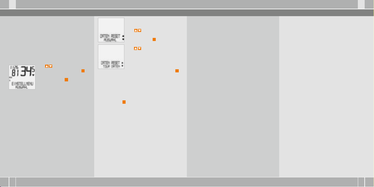
Mit zu EINSTELLMENU/
AUSWAHL. Bestätigen mit M.
Sie befinden sich jetzt im Einstell-Modus (mit C – 3 Sekunden
kommen Sie zurück zum Funktions-Modus).
Abfrage. AUSWAHL/RESET?
ACHTUN G: Dieser Schr itt kann nicht r ückgängig
gemacht w erden.
Bestätigen mit M, nur wenn Sie die ausgewählten
Daten löschen wollen. Das Display bestätigt:
DATEN RESET/RESET FERTIG. Automatische Rückkehr zu EINSTELLMENU/AUSWAHL.
Mit zu
DATEN RESET/AUSWAHL.
Bestätigen mit M.
Mit zu den Daten, die Sie
zurückstellen wollen:
B
DATEN RESET/TOUR DATEN
ODER
B
TOTAL KM
Bestätigen Sie Ihre Auswahl mit M.
VDO Cycle Parts gewährt für Ihren VDO-Computer
eine Garantie von 5 Jahren ab Kaufdatum. Die
Garantie erstreckt sich auf Material- und Verarbeitungsfehler am Computer selbst, am Sensor/
Sender und an der Lenkerhalterung. Kabel und
Batterien sowie Montagematerialien sind von
der Garantie ausgeschlossen. Die Garantie ist
nur dann gültig, wenn die betroffenen Teile nicht
geöffnet wurden (Ausnahme: Batteriefach des
Computers), keine Gewalt angewendet wurde und
keine mutwillige Beschädigung vorliegt.
Bitte bewahren Sie den Kaufbeleg sorgfältig auf,
da er im Reklamationsfall vorgelegt werden muss.
Bei einer berechtigten Reklamation erhalten Sie
von uns ein vergleichbares Austauschgerät. Ein
Anspruch auf Ersatz des identischen Modells
besteht nicht, wenn durch Modellwechsel die
Produktion des reklamierten Modells eingestellt
wurde.
Bitte wenden Sie sich mit allen Reklamationen
und Garantieansprüchen an Ihren Fachhändler,
bei dem Sie das Gerät gekauft haben. Oder senden
Sie Ihre Reklamation direkt an:
Cycle Pa rts GmbH
Große Ahlmühle 33
D-76865 Rohrbach (Germany)
Für technische Fragen stehen wir Ihnen jederzeit
unter folgender Hotline zur Verfügung:
+49 (0) 6 3 49 - 96 35 - 10.
Weitere technischen Informationen erhalten Sie
unter: www.vdocyclecomputing.com
Im Zuge der Weiterentwicklung behalten wir uns
technische Änderungen vor.
Page 11

X1DW VDO CYCLECOMPUTING20
D GB F I
I F GB D
www.vdocyclecomputing.com X1DW 21
7. Fehlerbehebung
Hier finden Sie eine Liste möglicher Fehler, ihrer Ursachen und was Sie dagegen tun können:
Fehler Möglic he Ursach e Behebung
Halbe Segmente in der Anzeige
(z.B. nach einem Batteriewechsel)
Keine Geschwindigkeits-Anzeige Abstand von Sensor zu Magnet
Keine Geschwindigkeits-Anzeige Computerkopf nicht korrekt
Keine Geschwindigkeits-Anzeige Radumfang ist nicht korrekt
Anzeige wird schwach Batterie leer Batterie prüfen, evtl. ersetzen
Anzeige wird schwach Temperaturen unter 5° machen
Computer-Software läuft nach
Batteriewechsel nicht korrekt
zu groß
in der Lenkerhalterung
eingerastet
eingestellt oder steht auf Null
die Anzeige träge
Batterie herausnehmen
und neu einsetzen
Position von Sensor und
Magnet korrigieren
Computerkopf in die Lenkerhalterung setzen, bis zum
Anschlag („click“) drehen
Radumfang einstellen
Bei normalen Temperaturen
arbeitet die Anzeige wieder
normal
8. Technische Spezifikationen
Comput er:
ca. 45 x 52 x 16 mm, Gewicht: ca. 45 g
Lenke rhalterun g:
Gewicht: ca. 15 g
Sender:
Gewicht ca. 20 g
Batte rie Compute r:
3V, Type 2032
Batte rie Lebens dauer Comp uter:
600 Fahr-Stunden, ca. 12.000 km (7400 m)
Batte rie Sender :
3V, Type 2032
Batte rie-Le bensdaue r Sender:
1000 Fahr-Stunden ca. 20.000 km (12.000 m)
Arbei ts-Tempera tur des Displ ays:
-15 °C to +60 °C
Geschwindigkeits-Bereich:
bei Radgröße 2155 mm, min 2.5 km/h,
max 199.5 km/h
Fahrze it Messber eich:
bis 23:59:59 HH:MM:SS
Tagest our-Zähle r Messbere ich:
bis 999,99 km oder mi
Gesa mt-KM 1 u. 2 Mes sbereich :
bis 99.999 km oder mi
Total Kil ometer Mes sbereich :
bis 199.999 km oder mi
Radum fang Einste llbereich :
von 100 mm bis 3999 mm (3,9 bis 157,4 inch)
Page 12

X1DW VDO CYCLECOMPUTING22
F I
I F
www.vdocyclecomputing.com X1DW 23
Preface
Congratulations
With your selection of a VDO computer you have opted for a technically very high quality appliance.
In order to fully benefit from the potential of the computer, we recommend that you carefully read this
manual. It contains all operating instructions and many other useful tips.
We hope you enjoy cycling with your VDO bike computer.
Cycle Parts GmbH
Pack contents
Please first check that this pack is complete:
1 VDO computer
Battery installed
1 speed transmitter
Battery installed
1 universal handlebar holder
Table of contents
1. Display 24
2. Operation 26
3. Functions 27
3.1 Information functions 27
in function mode
3.2 Cadence option 28
4. Installation 28
4.1 Fitting the transmitter, magnet 28
and handlebar holder
4.2 Switching on the computer 29
for the first time
4.3 Installing the battery in the computer 29
4.4 Placing the computer into 30
the handlebar holder
4.5 Transmitter pairing 30
5. Basic settings 31
5.1 Setting the language 31
5.2 Setting and measuring the wheel size 31
5.2.1 Select from tyre table 31
5.2.2 Setting using wheel circumference 33
5.3 Setting the CLOCK 34
5.4 Setting the total kilometres 35
5.5 Switch from bike 1 to bike 2 35
5.6 Service interval display
5.7 Sleep mode 37
5.8 Reset functions 38
6. Terms of guarantee 39
7. Troubleshooting 40
8. Technical spezifications 41
36
DGBD GB
1 rubber pad
for transmitter
1 spoke magnet
(clip magnet)
cable ties
for fitting the holder
and transmitter
„>>> P02“ links at the beginning of a chapter
are related to the respective picture in the
picture book!
Page 13
X1DW VDO CYCLECOMPUTING24
F I
I F
www.vdocyclecomputing.com X1DW 25
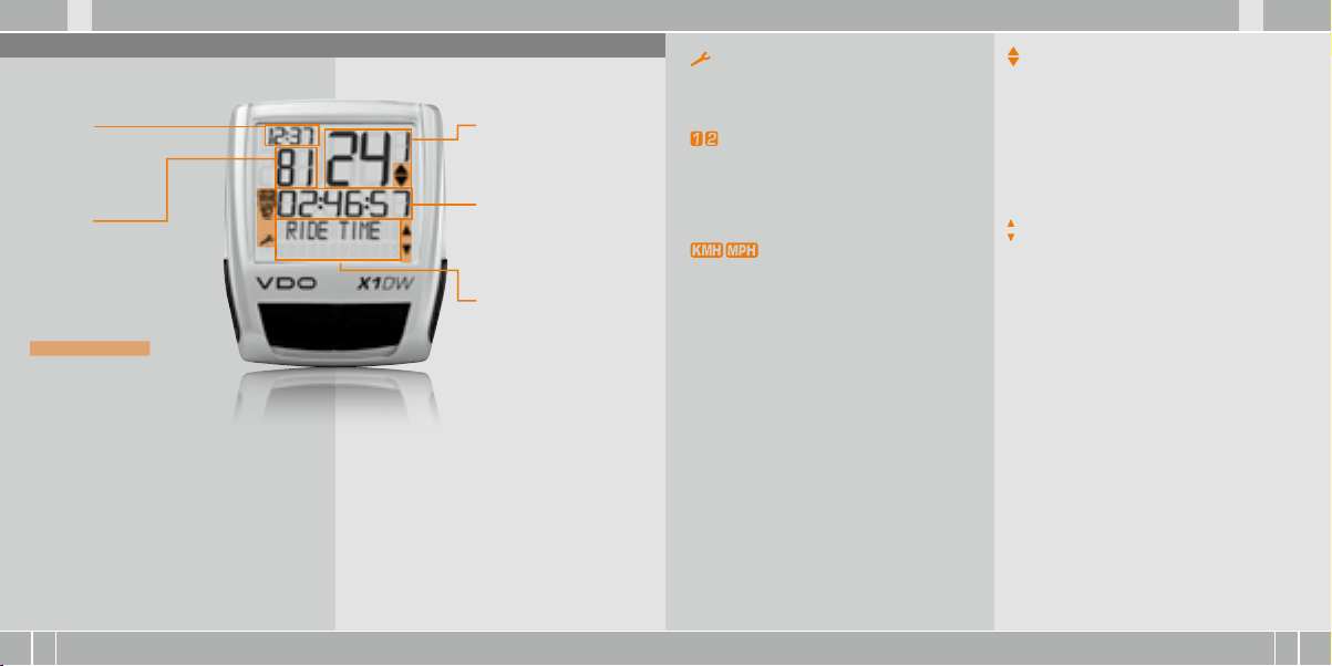
1. Display
The dis play can be div ided
into 5 se ctions:
Sect ion 1
alway s shows
the cur rent time.
Sect ion 2
shows the current cadence,
if the cadence transmitter is
installed (optional).
You will also find
indicator elements
on the di splay
You can find the description of
the individual indicators on
the right hand side.
Sect ion 3
shows the
current speed.
Sect ion 4
shows the value of the
display function/
information that you
selected.
Sect ion 5
shows the description of
the selected function in
the top line (info line). The
second line (menu line)
shows,
B
whether there is more
information „MORE“
B
whether there is
another selection
option „SELECT“
Serv ice indicat or
shows that your bike should go for a service.
You can set the service interval individually for
bike 1 and bike 2
Indica tor bike 1/ bike 2
The computer can work with two different settings for 2 bikes. The indicator shows which of the
two bikes you have chosen to use.
The total distances are accordingly counted and
stored separately for bike 1 and bike 2.
Mea suremen t unit (KMH or MPH)
The computer can display both KHM and MPH.
Distances are shown in kilometres or miles
accordingly.The indicator shows the selected
measurement unit
Speed d ifferenc e indicator ( current)
to spee d (average)
The computer compares the current speed
with the average speed.
The indicator shows
B
whether the current speed is higher than
the average (+1 KMH)
B
below the average (-1 KMH)
B
or matches the average
(tolerance +/- 1 KMH).
Menu pr ompt indica tor
When a submenu has been accessed, these indicators flash and show that there are other selection options or that the computer is waiting for
an entry (setting mode).
DGBD GB
Page 14

X1DW VDO CYCLECOMPUTING26
F I
I F
www.vdocyclecomputing.com X1DW 27
2. Operation
To make your computer easy to use, we have developed the EMC Easy Menu Control system.
The EMC makes your computer easier to operate
by means of a full text menu guidance,
as is used on most mobile phones.
C = CLEAR
DOWN
C
= CLEAR
In func tion mode:
B
Jump back a menu level from
the submenu.
In sett ing mode:
B
Jump back to function mode.
B
Correct an entry.
B
Jump back a digit.
= DOWN
In func tion mode:
B
Scroll downwards within
the functions.
In sett ing mode:
B
Scroll downwards within
the setting modes.
B
Decrease a digit.
Menu indicators on the display flash to show that
there are other selection options.
In function mode and setting mode, the computer is
operated using the 4 buttons.
M = MENU
UP
FUNCTION 3
FUNCTION 4
FUNCTION 5
FUNCTION 6
M
= MENU
In func tion mode:
B
Access available submenu.
B
Confirm selection.
You can recognise a submenu by
the flashing menu indicators.
In sett ing mode:
B
Select a setting.
B
Confirm a setting.
B
Confirm a selection made.
= UP
In func tion mode:
B
Scroll upwards within
the functions
In sett ing mode:
B
Scroll upwards within
the setting modes.
B
Increase a digit.
3. Functions
3.1 Information functions in function mode
TRIPDISTANCE
Shows the distance of the current trip since the
last reset.Maximum value 999.99 km.
If the maximum value is exceeded, the counter
starts again at zero. At the same time the values for
ride time and average speed are set back to zero
TRIPDISTANCE/MORE
MORE shows that there is a submenu for the main
menu TRIPDISTANCE. You open the submenu with
the M button. In the submenu you will find:
B
Total kilometres BIKE 1 ODO BIKE 1 up to a
maximum of 99,999 km.
B
Total kilometres BIKE 2 ODO BIKE 2 up to a
maximum of 99,999 km.
B
Total kilometres for Bike 1 + Bike 2 ODO TOTAL
up to a maximum of 199,999 km.
You leave the submenu by pressing C again.
RIDE TIM E
Shows the ride time of the current day‘s trip since
the last reset. Maximum 23:59:59 HH:MM:SS
If the maximum value is exceeded, the ride time
measurement starts again at zero. At the same
time the day‘s tripdistance and average speed are
set back to zero.
AVG SPEED
Shows the average speed, calculated from the
day‘s tripdistance and ride time, since the last reset
Accuracy: 2 decimal places.
The average speed is recalculated if the day‘s tripdistance or ride time exceeds the maximum value.
MAX S PEED
Shows the maximum speed on the current trip since
the last reset. Accuracy: 2 decimal places.
DGBD GB
Page 15

X1DW VDO CYCLECOMPUTING28
F I
I F
www.vdocyclecomputing.com X1DW 29
3.2 Cadence option
The cadence menu is only available if
B
the cadence transmitter is installed,
B
the transmitter was recognized during pairing.
After pairing the cadence transmitter, the current cadence is shown in section 2 of the display.
In function mode it is possible to select the CADENCE/
MORE menu using the using the up/down
buttons.
Confirming with M opens the menu and gives you
access to the information.
Using you come to:
B
AVG CADENCE
B
MAX CADENCE
Resetting the trip data also sets the cadence data
back to zero.
4 Installation
4.1 Fitting the transmitter, magnet and handlebar holder >>> P01
Start by fitting the transmitter and magnet.
ATTENTION: The transmitting distance between
the transmitter and the computer on the handlebars should not be more than 60 cm (transmission
range).
step 1 Place the rubber pad under the transmitter.
Fit the transmitter on the same side of the fork
where you later want to fit the computer to the
handlebars (right or left) using the cable ties supplied (loose at first, do not pull tight just yet).
ATTENTION: The sensor mark on the transmitter
must point to the spokes.
Depending on the room available, the transmitter
can be fitted at the front on the forks, inner side
of the fork or backside of the forks. >>> P04
step 2 Place spoke magnet around an outer
spoke. The silver middle of the magnet points
towards the transmitter. Align the magnet to the
sensor mark on the transmitter with a gap
of about 1 – 5 mm.
Step 3 Align transmitter and magnet for good and
fasten in place: Pull cable ties tight and push
magnet in firmly.
Step 4 Decide whether fitting to handlebar or
stem and turn the base of the handlebar holder
by 90° accordingly. To do so, undo the screws in
the holder, take out the foot and turn it 90°, insert
and tighten the screws again.
ATTENTION: Do not over t ighten screws .
step 5 Guide the cable ties through the slot in the
handlebar holder, place around the handlebars
or the stem and pull (do not pull tight just yet).
Step 6 If fitting to handlebar: Align computer
angle to achieve optimum readability. Now pull
cable ties tight. Snip off protruding ends with
clippers.
4.2 Switching on the computer for the first time >>> P02, Display see Chapter 5.1
Waking u p from despa tch mode
The computer is delivered with a battery installed.
To reduce the battery consumption, the computer
is put into despatch mode. The display is empty
(no display).
To wake it up out of despatch mode, press the
button simultaneously for a few seconds.
The computer is now ready for use and tells you
so by showing the language setting.
See also Chapter 5.1
4.3 Installing the battery in the computer >>> P05
Your VDO computer is supplied with a 3V battery
(type 2032).
The bat tery is alre ady insta lled when sup plied.
To change the battery, proceed as follows:
step 1 Place the battery in the computer casing
with the +terminal facing up.
Step 2 Make sure that the battery does not
get wedged.
step 3 Take care that the rubber seal lies flat on
the battery compartment lid.
Step 4 Insert the battery compartment lid into the
opening and turn it with a coin to the right as far
as it will go (approx. 1/3 turn).
TIP for ch anging batte ry: VDO r ecommends cha nging the ba ttery once a y ear. Buy a new bat tery in
good time to ensure the wireless transmission
works perfectly. When the b attery is cha nged,
all sett ings and the tot al kilometr es cycled
are sav ed.
DGBD GB
Page 16

X1DW VDO CYCLECOMPUTING30
www.vdocyclecomputing.com X1DW 31
IF
4.4 Placing the computer into the handlebar holder >>> P06
The VDO twist-click system fastens the computer
securely with the handlebar holder.
Step 1 Place computer into the holder in 10 o‘clock
position.
Step 2 Twist computer to the right to 12 o‘clock position and click into the holder system.
Step 3 To take the computer out, twist to the left
(do not push or pull).
How to remember: Rigid to the Right, Loose to the Left
4.5 Transmitter pairing
The speed and cadence signals (Option: Item no.
7702) will be transmitted digitally and encoded to
your computer. This technology is less prone to
problems than analogue transmission. This way,
when riding in a group there are no data overlaps
(cross talk). So that the computer acquires the
digital encodings from the transmitter, a pairing
must be made:
step 1 Place the computer into the handlebar
holder. The display for the speed and the cadence
now flashes. The flashing shows that the computer is looking for its transmitter.
step 2 Spin the front wheel or simply set off and
the computer acquires the digital encodings.
When the computer has found the transmitters
and has acquired the encodings (pairing), the
speed and cadence are shown on the display.
ATTENT ION: The time wi ndow for pair ing is
5 minutes . If you do not sta rt cycling du ring
these 5 mi nutes, no pair ing takes place .
Speed a nd cadence ar e not displayed.
The pa iring then has to b e repeated:
B
Place the comp uter back into the h andlebar
holder OR
B
press the bu ttons C + M togethe r.
5. Basic settings
5.1 Setting the language
Using the buttons, go to
SETTINGS/SELECT.
Confirm with M.
You are now in setting mode
(pressing C for 3 seconds gets
you back to function mode).
to LANGUAGE SELECT.
Confirm with M.
5.2 Setting and measuring the wheel size
You must set the wheel size (wheel roll circumference) of your bike so that your VDO computer
can measure correctly.
5.2.1 Setting using tyre table
The common types of tyres are listed in the tyre
table. If your tyre type is not listed, we recommend
entering the wheel size manually.
I F DGBD GB
to LANGUAGE ENGLISH.
Confirm with M.
ENGLISH SELECT OK? Confirm with M.
LANGUAGE SELECT DONE. The computer automatically returns to the start menu SETTINGS/SELECT.
There are 2 ways of doing this:
The values given in the table are approximate
values. These values differ according to brand, tyre
height and tyre profile. This can consequently also
lead to discrepancies in the distance measured
and the speed shown.
Page 17

X1DW VDO CYCLECOMPUTING32
F I
I F
www.vdocyclecomputing.com X1DW 33
16 x 1,7 5 1272 50,1
20 x 1,7 5 1590 62,6
24 x 1 ⅜ 1948 76,7
24 x 1, 75 1907 75,1
26 x 1 1973 77,7
26 x 1,5 2026 79,8
26 x 1,6 2051 80,7
26 x 1,7 5 2070 81,5
26 x 1,9 2089 82,2
26 x 2,0 0 2114 83,2
26 x 2, 125 2133 84,0
26 x 1 ⅜ 2105 82,9
26 x ¾ 1954 76,9
27 x 1 ¼ 2199 86,6
28 x 1,5 2224 87,6
28 x 1, 75 2268 89,3
28 x 1 ½ 2265 89,2
28 x 1 ⅜ 2205 86,8
30-622 2149 84,6
32-622 2174 85,6
37-62 2 2205 86,8
40-622 2224 87,6
mm-value inch-value
How to se t the tyre size b y selectin g the tyre:
Using go to SETTINGS/
SELECT. Confirm with M.
You are now in setting mode
(pressing C for 3 seconds gets
you back to function mode).
The confirmation question appears “Tyresize“/
SELECT OK? When the displayed tyre size matches
the one you want, confirm with M.
The display confirms WHEELSIZE/SET DONE
Automatic return to SETTINGS/SELECT.
Using up/down go to
WHEELSIZE/SET.
Confirm with M.
MEASUREMENT/KMH.
Confirm with M or to
change to MPH.
WHEELSIZE/BIKE 1 (use to
go to setting for bike 2).
Confirm with M.
WHEELSIZE/ TYRE SELECT.
Confirm with M.
TYRE SELECT/SELECT.
Now select your tyres using
. Confirm with M.
5.2.2 Setting using wheel circumference >>> P07
To enter the wheel size manually, you must first
measure the wheel roll circumference on your bike.
Meas uring wheel ro ll circumfe rences:
step 1 Precisely align valve on the front wheel
vertically to the ground.
Step 2 Mark this spot on the ground with a line
(e.g. chalk).
step 3 Push the bike forwards one turn of the
wheel until the valve is vertical to the ground
again.
Step 4 Also mark this spot on the ground.
Step 5 Measure the distance between the two
marks.That is your wheel circumference
(=roll circumference).
Step 6 Enter the wheel circumference measured
in this way into your VDO computer.
ATTENT ION: If you have se lected KMH dis play,
you must e nter the wheel ci rcumference in m m
(If MPH displ ay is selected, e nter the wheel
circumfe rence in inche s).
How to se t the wheel siz e manually:
Using go to SETTINGS/
SELECT. Confirm with
You are now in setting mode
(pressing C for 3 seconds gets
you back to function mode)
Using go to WHEELSIZE/
SET. Confirm with M .
MEASUREMENT/KMH.
Confirm with M or to
change to MPH.
WHEELSIZE/BIKE 1.
(use to go to setting for
bike 2) Confirm with M.
Using go to
WHEEL-SIZE/MANUAL SET.
Confirm with M.
M
DGBD GB
Page 18

X1DW VDO CYCLECOMPUTING34
F I
I F
www.vdocyclecomputing.com X1DW 35
BIKE 1 ...SET SIZE/CONTINUE
Now set the wheel roll circumference measured using .
Confirm the entry with M.
BIKE 1/SET OK? Confirm with M.
The display confirms: WHEELSIZE/SET DONE.
Automatic return to SETTINGS/SELECT.
Attent ion: The facto ry settings f or bike 1 = 2155
mm and for b ike 2 = 2000 mm. If y ou do not enter
any whee l sizes, the comp uter works wit h these
factor y settings . The values me asured in thi s
way for spe ed, distan ce etc. can diff er widely
from the a ctual value s.
5.3 Setting the clock
How to se t the clock:
Using go to SETTINGS/
SELECT. Confirm with M.
You are now in setting mode
(pressing C for 3 seconds gets
you back to function mode)
Using go to CLOCK/SET.
Confirm with M.
CLOCK/SET OK? Confirm with M.
CLOCK/24-H-MODE (you can
switch to 12-H mode using .
Confirm with M.
The display confirms: CLOCK/SET DONE.
Automatic return to SETTINGS/SELECT.
CLOCK...SET HOUR/CONTINUE
Set the hours using .
Confirm the hour setting
with M.
CLOCK...SET MINUTES/
CONTINUE. Set the minutes
using . Confirm the
minutes setting with M.
5.4 Setting the total kilometres
You can program the values on the distance counter at any time (e.g. at the end of a season).
Using go to SETTINGS/
SELECT. Confirm with M.
You are now in setting mode
(pressing C for 3 seconds gets
you back to function mode).
Using go to ODOMETER/
SET. Confirm with M.
ODO BIKE 1/SET OK? Confirm with M.
The display confirms ODO BIKE 1/SET DONE.
Automatic return to SETTINGS/SELECT.
ODOMETER/ODO BIKE 1
(use to go to setting for
BIKE 2). Confirm with M.
ODO BIKE 1 ...SET DISTANCE/
CONTINUE.
You can set the flashing digits
using .
To access the next digit, confirm with M. Repeat the steps
until the last digit on the right
is flashing. Confirm with M.
5.5 Switch from Bike1 to Bike2 >>> P03
Your VDO computer can be used on 2 bikes.
If you switch from bike 1 to bike 2, the computer
recognises the transmitter from bike 2. The
computer then automatically switches to bike 2.
All data are now saved for bike 2. When you use
the computer again on bike 1, transmitter 1 is
recognised. The computer switches to bike 1.
The data are now saved for bike 1.
Note: Th e transmitter o n bike 2 must have be en
set to bike 2 b efore using it the fir st time. >>> P03
The selected Bike 1 or 2 is shown
on the display bottom left ( ).
DGBD GB
Page 19

X1DW VDO CYCLECOMPUTING36
F I
www.vdocyclecomputing.com X1DW 37
D
5.6 Service interval display
The VDO service interval display reminds you to
have your bike checked in the workshop.
You can switch the service interval ON or OFF.
You can set separate service intervals for 2 bikes
When the set service interval distance has been
reached:
B
The -symbol flashes on the display.
B
The information line displays
BIKE SERVICE/BIKE 1
You should now either carry out the recommended bike check yourself or have the bike checked
by your dealer.
Press any button. The text BIKE SERVICE disappears again. After another 50 km the -also disappears. You can also switch off the flashing
symbol. To do so, enter the service interval again.
How to se t the servi ce interva l:
Using go to SETTINGS/
SELECT. Confirm with M.
You are now in setting mode
(pressing C for 3 seconds gets
you back to function mode).
Using go to BIKE SERVICE/
SET. Confirm with M.
Repeat the steps until the last digit on the right
is flashing. Confirm with M.
BIKE 1/SET OK? Confirm with M.
The display confirms: BIKE SERVICE/SET DONE.
Automatic return to SETTINGS/SELECT.
BIKE SERVICE/ON (switch to OFF
using ). Confirm with M.
BIKE SERVICE/BIKE 1
(use to switch to bike 2)
Confirm with M.
BIKE 1 ...SET DISTANCE/
CONTINUE. You can set the flashing digits using To access
the next digit, confirm with M.
5.7 Sleep mode
Your VDO computer is equipped with a two-fold
sleep mode function.
In sleep mode, a large part of the display is switched
off to save battery power. Time and service
interval display continue to be displayed.
Sleep m ode 1 switches itself on after 5 minutes if
no speed impulses are processed and no button
is pressed.
Sleep m ode 1 is ended when speed impulses
are processed again (when cycling) or a button
is pressed.
In Sleep -Modus 2 the wireless receiver is also
switched off. (afte r 15 min).
The display shows SLEEP
MODE/PRESS BUTTON
Befor e continuing t o ride,
you must p ress a butto n to
switch t he receive r back on.
The display for the speed and
the cadence flashes.
The computer now waits for speed and cadence
signals (as long as cadence is installed). Simply set
off riding now. The computer acquires the digital
encodings from the transmitter.
DGBFIGB
Page 20

X1DW VDO CYCLECOMPUTING38
F I
I F
www.vdocyclecomputing.com X1DW 39
D
5.8 Reset functions
You use the RESET function to set any of these back
B
TOUR DATA
B
ODO TOTAL
With the respective reset modes, the following
information is deleted:
B
TOUR DATA: Day‘s tripdistance, ride time,
average speed, max. speed, cadence (option)
B
ODO TOTAL: Total km, km bike 1, km bike 2
Using go to SETTINGS/
SELECT. Confirm with M.
You are now in setting mode
(pressing C for 3 seconds gets
you back to function mode).
Query: SELECTED DATA/RESET?
ATTENT ION: This step c annot be reve rsed.
Only confirm with
selected data. The display confirms:
DATA RESET/RESET DONE.
Automatic return to SETTINGS/SELECT.
Using go to DATA RESET/
SELECT. Confirm with M.
Use to go to the data you
want to reset:
B
DATA RESET/TOUR DATA
OR
B
DATA RESET/ODO TOTAL
Confirm your selection with M.
M
, if you want to delete the
6. Terms of guarantee
VDO Cycle Parts grants a guarantee of 5 years
from the date of purchase for your VDO computer.
The guarantee covers material and processing defects on the computer itself, on the sensor/transmitter and on the handlebar holder. Cables and
batteries as well as assembly materials are excluded
from the guarantee. The guarantee is only valid
if the parts concerned have not been opened
(exception: battery compartment on the computer), no force has been used and there is
no sign of wilful damage.
Please take care to keep the receipt as it must
be presented in the event of a complaint.
If the complaint is justified, you will receive a
comparable replacement appliance from us.
You are not entitled to an identical replacement
model if the model in question is no longer in
production due to a change of model.
Please contact the dealer from whom you
purchased the device for all complaints and
guarantee claims. Or send your complaint
directly to:
Cycle Pa rts GmbH
Große Ahlmühle 33
D-76865 Rohrbach (Germany)
We would be pleased to answer any technical
questions you might have at the following
hotline number:
+49 (0) 6 3 49 - 96 35 - 10.
Additional technical information is available at:
www.vdocyclecomputing.com
We reserve the right to make technical changes in
the course of further development.
DGBGB
Page 21

X1DW VDO CYCLECOMPUTING40
F I
I F GB D
www.vdocyclecomputing.com X1DW 41
Here you can find a list of possible faults, their causes and what you can do about them:
Error Possible cause Correction
Half segments on the display
(e.g. after a battery change)
No speed display Distance from sensor to
No speed display Computer not properly clicked
No speed display Wheel circumference is not
Computer software not running
correctly after battery change
magnet too big
in the handlebar holder
correctly set or is at zero
Take out battery and insert
again
Correct position of sensor
and magnet
Place computer head in the
handlebar holder, twist until
it clicks
Set wheel circumference
Display becomes weak Battery dead Check battery, replace if nec.
Display becomes weak Temperatures under 5° make
the display sluggish
At normal temperatures the
display will work normally
again
8. Technical spezifications
Comput er:
approx. 45 x 52 x 16 mm, weight: approx. 45 g
Handl ebar holde r:
weight: approx. 15 g
Transmitter:
weight approx. 20 g
Comput er batter y:
3V, type 2032
Transmi tter batte ry:
3V, type 2032
Comput er batter y life-s pan:
600 cycling hours, approx. 12,000 KM (7400 M)
Transmi tter batte ry life- span:
1000 cycling hours (approx. 20,000 KM (12,000 M)
Workin g temperatu re of the disp lay:
-15 °C to +60 °C
GB DGBD
Speed r ange:
for wheel size 2155 mm, min 2.5 km/h, max 199.5 km/h
Ride ti me measure ment range:
up to 23:59:59 HH:MM:SS
Day‘ s trip counter m easurem ent range:
up to 999.99 km or mi
Total KM 1 a nd 2 measur ement range :
up to 99,999 km or mi
Total ki lometers m easureme nt range:
up to 199,999 km or mi
Wheel ci rcumfere nce setting r ange:
from 100 mm to 3999 mm (3.9 to 157.4 inches)
Page 22

X1DW VDO CYCLECOMPUTING42
D GB F I
I F GB D
www.vdocyclecomputing.com X1DW 43
Préface
Merci !
En choisissant un compteur VDO, vous avez choisi un appareil aux qualités techniques élevées. Nous
vous recommandons de lire attentivement la présente notice d‘utilisation de manière à utiliser au
mieux le potentiel de votre compteur. Celle-ci vous fournira toutes les informations nécessaires pour
l‘utilisation de votre compteur, ainsi que d‘autres astuces utiles.
Contenu de l‘emballage
Veuillez tout d‘abord vérifier si l‘emballage contient toutes les pièces requises :
1 compteur VDO
Batterie mise en place
1 émetteur de vitesse
Batterie mise en place
1 support universel
pour guidon
Sommaire
1. Ecran 44
2. Utilisation 46
3. Fonctions 47
3.1 Fonctions d’information en mode 47
de fonctionnement
3.2 Option « Fréquence de pédalage » 48
4. Installation 48
4.1 Montage de l’émetteur, de l’aimant 48
et du support pour guidon
4.2 Premier démarrage du compteur 49
4.3 Mise en place de la pile 49
dans le compteur
4.4 Mise en place du compteur dans 50
le support du guidon
4.5 Couplage de l’émetteur 50
5. Réglages de base 51
5.1 Régler la langue 51
5.2 Régler et mesurer la taille de la roue 51
5.2.1 Sélection dans le tableau de gonflage 51
des pneumatiques
5.2.2 Réglage au moyen de 53
la circonférence de la roue
5.3 Régler l’heure 54
5.4 Régler le kilométrage total 55
5.5 Commutation VELO 1 / VELO 2 55
5.6 Affichage des intervalles de service 56
5.7 Mode « Veille » 57
5.8 Fonction de mise à zéro 58
6. Conditions de garantie 59
7. Diagnostic de pannes 60
8. Caractéristiques techniques 61
1 rondelle en caoutchouc
pour émetteur
1 aimant pour rayon
(aimant à clipser)
ligatures de câbles
pour le montage du support
et de l’émetteur
„>>> P02“ au début d’un chapitre renvoie
à la photo concernée dans le livret de photos !
Page 23

X1DW VDO CYCLECOMPUTING44
D GB F I
I F GB D
www.vdocyclecomputing.com X1DW 45
1. Ecran
L’écran peu t être subdiv isé en 5 zones :
La zone 1
indique t oujours
l’heu re actuelle .
La zone 2
indique la cadence actuelle
lorsqu’un émetteur de
cadence est installé (option).
L’écran indi que égalem ent
des élé ments d’in dication .
La description des différents
indicateurs se trouve sur
la page de droite.
La zone 3
indique la vitesse
actuelle.
La zone 4
indique la valeur pour
la fonction / l’information
sélectionnée.
La zone 5
indique, dans la ligne
supérieure (ligne d’informations), la désignation
de la fonction sélectionnée. La seconde ligne
(ligne de menu) indique
B
« PLUS » si d’autres
informations sont
disponibles.
B
« CHOIX » si une autre
possibilité de sélection
existe.
Indica teur de ser vice
Indique que votre vélo devrait être révisé.
L’intervalle de service peut être déterminé individuellement pour la roue 1 et la roue 2.
Indica teur Vélo 1 / Vélo 2
Le compteur peut être utilisé avec deux réglages
différents, pour 2 vélos. L’indicateur indique quel
vélo a été sélectionné. Les kilométrages totaux
sont comptabilisés et enregistrées indépendamment pour le vélo 1 et le vélo 2.
Uni té de mesure (K MH ou MPH)
Le compteur peut travailler soit en KMH, soit en
MPH. Les distances s’affichent alors en kilomètres
ou en milles. L’indicateur indique l’unité de mesure sélectionnée.
Indica teur de diff érence ent re la vitess e
(actu elle) et la vit esse (moyen ne)
Le compteur compare la vitesse actuelle
avec la vitesse moyenne.
L’indicateur indique
B
si la vitesse actuelle est supérieure
à la moyenne (+ 1 KMH),
B
si la vitesse actuelle est inférieure
à la moyenne (- 1 KMH),
B
ou si la vitesse actuelle correspond
à la moyenne (tolérance de +/- 1 KMH).
Indica teur de comma nde du menu
Lorsqu’un sous-menu est appelé, ces indicateurs
clignotent et indiquent que d’autres possibilités
de sélection existent ou que le compteur attend
une saisie (mode de réglage).
Page 24

X1DW VDO CYCLECOMPUTING46
D GB F I
I F GB D
www.vdocyclecomputing.com X1DW 47
2. Utilisation
Le système EMC (= Easy Menu Control) a été développé
afin de faciliter l’utilisation de votre compteur.
L’EMC facilite l’utilisation du compteur au moyen
d’une navigation en plein texte dans les
menus, identique à celle de la plupart des
C = CLEAR
DOWN
C
= CLEAR
En mode d e fonctionn ement:
B
Revenir d’un sous-menu à
un niveau supérieur.
En mode d e réglage :
B
Revenir en mode de
fonctionnement.
B
Corriger une saisi.
B
Revenir en arrière d’un chiffre.
= DOWN
En mode d e fonctionn ement:
B
Reculer dans les fonctions.
En mode d e réglage :
B
Reculer dans les modes de réglage.
B
Diminuer un chiffre.
téléphones portables. Les indicateurs des menus
à l’écran indiquent par un clignotement qu’il existe
d’autres possibilités de sélection.
En mode de fonctionnement et de réglage,
l’utilisation se fait au moyen de 4 touches.
M = MENU
UP
FONCTION 3
FONCTION 4
FONCTION 5
FONCTION 6
M
= MENU
En mode d e fonctionn ement:
B
Appeler un sous-menu disponible.
B
Confirmer une sélection.
Vous reconnaissez un sous-menu au
clignotement des indicateurs de menu.
En mode d e réglage :
B
Sélectionner un réglage.
B
Confirmer un réglage auquel.
vous venez de précéder.
B
Confirmer une sélection.
= UP
En mode d e fonctionn ement:
B
Avancer dans les fonctions.
En mode d e réglage :
B
Avancer dans les modes
de réglage.
B
Augmenter un chiffre.
3. Fonctions
3.1 Fonctions d’information en mode de fonctionnement :
DISTANCEJOUR
Indique la distance du tour actuel depuis la dernière remise à zéro. Valeur maximale : 999,99 km
Le compteur revient à zéro lorsque la valeur maximale est dépassée. Les valeurs pour la durée du
tour et la vitesse moyenne sont alors également
remises à zéro.
DISTANC EJOUR / PLUS
PLUS indique qu’un sous-menu existe pour le
menu principal DISTANCEJOUR. Ce sous-menu
peut être ouvert au moyen de la touche M. Dans le
sous-menu se trouvent :
B
Kilométrage total pour le VELO 1 jusqu’à
max. 99 999 km
B
Kilométrage total pour le VELO 2 jusqu’à
max. 99 999 km
B
Somme des kilométrages totaux pour VELO 1 +
VELO 2, jusqu’à max. 199 999 km
Ce sous-menu peut être quitté au moyen de la
touche C.
CHRONO J OUR
Indique la durée du tour actuel depuis la dernière
remise à zéro. Max. 23:59:59 HH:MM:SS.
La mesure de la durée revient à zéro lorsque la
valeur maximale est dépassée. Le tour du jour,
ainsi que la vitesse moyenne sont alors également
remis à zéro.
VITESS E MOY
Indique la vitesse moyenne, calculé sur base de la
distance du tour et de sa durée, depuis la dernière
remise à zéro. Précision : 2 décimales. La vitesse
moyenne est à nouveau calculée lorsque la distance
du tour ou sa durée dépasse la valeur maximale.
VITESS E MAX
Indique la vitesse maximale du tour actuel depuis la
dernière remise à zéro. Précision : 2 décimales.
Page 25

X1DW VDO CYCLECOMPUTING48
D GB F I
I F GB D
www.vdocyclecomputing.com X1DW 49
3.2 Option « Fréquence de pédalage »
Le menu Cadence est uniquement disponible
lorsque
B
l’émetteur de cadence est installé,
B
l’émetteur a été installé lors du couplage.
Après le couplage de l’émetteur de cadence, la cadence actuelle s’affiche dans la zone 2 de l’écran.
En mode de fonctionnement, les touches .
permettent de sélectionner le menu CADENCE PEDA /
PLUS. Appuyer sur M pour ouvrir le menu et accéder aux informations.
Les touches permettent d’accéder à :
B
CADENCE MOY (cadence moyenne de pédalage).
B
CADENCE MAX (cadence maximale de pédalage).
La MISE A ZERO des données relatives au tour
remet également à zéro les données relatives à
la cadence.
4 Installation
4.1 Montage de l’émetteur, de l’aimant et du support pour guidon >>> P01
Commencer pa r le montage de l’ém etteur et de
l’aimant.
ATTENTION : L’écart entre l’émetteur et le compteur
placé sur le guidon ne doit pas dépassé 60 cm
(portée des ondes).
Etap e 1 Placer la rondelle en caoutchouc sous
l’émetteur. Monter l’émetteur sur la fourche, du
côté où vous souhaitez monter le compteur
(à droite ou à gauche), au moyen d’une ligature
de câble (sans la serrer dans un premier temps.
ATTENTION : La marque du capteur sur l’émetteur
doit être orientée vers les rayons.
En fonction de l’espace disponible, l’émetteur
peut être monté à l’avant de la fourche, au centre
ou à l’arrière de la fourche. >>> P04
Etap e 2 Placer l’aimant pour rayon autour d’un
rayon extérieur. Le cœur argenté de l’aiment doit
être orienté vers l’émetteur. Aligner l’aimant sur la
marque du capteur sur l’émetteur, à une distance
de 1 à 5 mm.
Etap e 3 Aligner définitivement l’émetteur et
l’aimant et les fixer : serrer la ligature de câble et
serrer fermement l’aimant.
Etap e 4 Tourner le support pour guidon à 90°
selon que le compteur doit être monté sur le
guidon ou le cadre. A cette fin, desserrer les vis
du support, retirer le pied et le tourner à 90°,
le remettre en place et resserrer les vis.
ATTENT ION : Ne pas se rrer les vis t rop fermeme nt.
Etap e 5 Faire passer une ligature de câbles dans
la fente du support du guidon pour le placer
sur le guidon ou le cadre et serrer (pas encore
totalement).
Etap e 6 En cas de montage sur le guidon : Déterminer l’angle d’inclinaison du compteur en vue
de garantir une lisibilité parfaite. Serrer alors
totalement la ligature de câbles. Couper les extrémités au moyen d’une pince.
4.2 Première mise en service >>> P02, écran, voir chapitre 5.1
Quitt er le mode d’env oi
Le compteur est fourni avec une batterie en place.
Le compteur est placé en mode d’envoi afin de
réduire la consommation de la batterie.
L’écran est vide (aucun affichage).
Pour quitter le mode d’envoi, appuyez sur les
touches simultanément pendant quelques
secondes. Le compteur est alors prêt à fonctionner
et revient au réglage de la langue.
Voir au chapitre 5.1.
4.3 Mise en place de la pile dans le compteur >>> P05
Votre compteur VDO est fourni avec une pile 3V
(type 2032). La pile est déjà mise en place à la
livraison. Procéder comme suit pour remplacer
la pile :
Etap e 1 Mettre la pile en place dans le boîtier du
compteur, pole + vers le haut.
Etap e 2 Veiller à ce que la pile ne s’incline pas.
Etap e 3 Veiller à ce que le joint en caoutchouc soit
bien à plat dans le couvercle du compartiment
à batterie.
Etap e 4 Placer le couvercle du compartiment à batterie dans l‘ouverture et le faire tourner vers la droite
au moyen d‘une pièce de monnaie jusqu‘au point de
butée (rotation d‘env. 1/3).
ASTU CE pour le rempla cement de la pile : V DO
recomm ande de rempla cer la pile chaque a nnée.
Achete z une nouvell e batterie bi en à temps afin de
garant ir le foncti onnement pa rfait de la tr ansmission par ondes radio. Tous les ré glages et le kilo métra ge total sont enr egistrés lor s du remplacement de l a pile.
Page 26

X1DW VDO CYCLECOMPUTING50
D GB F I
I F GB D
www.vdocyclecomputing.com X1DW 51
4.4 Mise en place du compteur dans le support du guidon >>> P06
Le système Twist-Click VDO fixe le compteur en toute
sécurité au support pour guidon.
Etap e 1 Placer le compteur dans son support,
tourné à « 10 heures ».
Etap e 2 Tourner le compteur vers la droite « twist »
et l‘enclencher, « à midi », dans le système de maintien « clic ».
Etap e 3 Pour retirer le compteur, le tourner vers la
gauche (sans pousser, ni tirer).
4.5 Couplage de l’émetteur
Les signaux de vitesse et de fréquence de pédalage
(option : n° d’article 7702) sont transmis à votre
compteur de manière digitale et codée. Cette technique est moins sensible aux perturbations qu’une
transmission analogique. Il n’y a donc aucun problème d’interférence lors des sorties en groupe
(pas de Cross Talk). Un couplage doit être effectué
pour que le compteur détecte les codages digitaux
de l’émetteur :
step 1 placer le compteur dans son support sur le
guidon. L’affiche de la vitesse et de la cadence clignote. Le clignotement indique que le compteur
recherche son émetteur.
step 2 Tourner la roue avant ou démarrer tout
simplement ; le capteur définit alors les codages
digitaux.
Une fois que le compteur a trouvé l’émetteur et a
déterminé les codages (couplage), la vitesse et la
cadence apparaissent à l’écran.
ATTENT ION : Le couplag e doit être eff ectué dans
les 5 minute s.Le coupla ge n’aura pas l ieu si vous
ne démar rez pas da ns ce délai. La v itesse et la
fréqu ence de pédala ge ne s‘affiche nt pas.
Le coupla ge doit alor s être répété :
B
Placer à nouv eau le compteur sur le s upport
du guidon OU
B
Enfoncer les to uches C + M .
5. Réglages de base
5.1 Régler la langue
Utiliser les touches
pour accéder à REGLAGES/
CHOIX. Confirmer avec M.
Vous vous trouvez alors dans
le mode de réglage (enfoncer la
touche C pendant 3 secondes
pour revenir au mode de fonctionnement).
Touches pour accéder
à LANGUAGE SELECT.
Confirmer avec M.
FRANÇAIS CHOIX OK ? Confirmer avec M.
Message du compteur : LANGUE CHOIX OK
Le compteur revient alors automatiquement au
menu de départ REGLAGE / CHOIX.
5.2 Régler et mesurer la taille de la roue
Pour que les mesures de votre compteur VDO
soient correctes, vous devez tout d‘abord régler
la taille de la roue (circonférence de la roue).
Vous avez 2 possibilités :
5.2.1 Sélection dans le tableau de gonflage des pneumatiques
Les types de pneus courants sont repris dans
le tableau de gonflage des pneumatiques. Si vous
n’y trouvez pas votre type de pneus, nous vous
recommandons de saisir manuellement la taille
de la roue.
Les valeurs données dans le tableau sont des
valeurs approximatives. Ces valeurs peuvent varier
en fonction de la marque, de la hauteur et du
profil des pneus. Il peut donc exister des écarts
pour la distance mesurée et la vitesse affichée.
Touches pour accéder
à LANGUE FRANÇAIS.
Confirmer avec M.
Page 27

X1DW VDO CYCLECOMPUTING52
D GB F I
I F GB D
www.vdocyclecomputing.com X1DW 53
16 x 1,7 5 1272 50,1
20 x 1,7 5 1590 62,6
24 x 1 ⅜ 1948 76,7
24 x 1, 75 1907 75,1
26 x 1 1973 77,7
26 x 1,5 2026 79,8
26 x 1,6 2051 80,7
26 x 1,7 5 2070 81,5
26 x 1,9 2089 82,2
26 x 2,0 0 2114 83,2
26 x 2, 125 2133 84,0
26 x 1 ⅜ 2105 82,9
26 x ¾ 1954 76,9
27 x 1 ¼ 2199 86,6
28 x 1,5 2224 87,6
28 x 1, 75 2268 89,3
28 x 1 ½ 2265 89,2
28 x 1 ⅜ 2205 86,8
30-622 2149 84,6
32-622 2174 85,6
37-62 2 2205 86,8
40-622 2224 87,6
Comme nt régler la ta ille de la rou e en sélecti onnan t un type de pne u ?
Val. en mm Val. en pouces
Touches pour accéder
à REGLAGES / CHOIX.
Confirmer avec M.
Vous vous trouvez alors en mode
de réglage (enfoncer la touche C
pendant 3 secondes pour revenir
au mode de fonctionnement)
Une demande de contrôle apparaît :
« Taille du pneu » / CHOIX OK ? Si la taille indiquée
correspond à celle souhaitée, confirmer avec M.
L’écran confirme avec TAILLE ROUE / REGLAGE OK.
Retour automatique à REGLAGES / CHOIX.
Touches pour accéder à
TAILLE ROUE / REGLAGE.
Confirmer avec M.
DIMENSION / KMH
Confirmer avec M ou utiliser
les touches pour passer
à MPH.
TAILLE ROUE / VELO 1
(utiliser les touches pour
passer au réglage du vélo 2).
Confirmer avec M.
TAILLE ROUE / TYPE PNEU.
Confirmer avec M.
TYPE PNEU / SELECT.
Sélectionner le type de pneu
avec les touches .
Confirmer avec M.
5.2.2 Réglage au moyen de la circonférence de la roue >>> P07
Pour saisir manuellement la taille de la roue, vous
devez tout d’abord mesurer la circonférence de
votre roue.
Mesur e de la circonf érence de la ro ue :
Etap e 1 Aligner la valve de la roue avant précisé-
ment à la verticale par rapport au sol.
Etap e 2 Marquer ce point au sol en y traçant
un trait (par ex. à la craie).
Etap e 3 Faire avancer la roue d‘un tour jusqu‘à ce
que la valve se retrouve à nouveau à la verticale
par rapport au sol.
Etap e 4 Marquer également ce point au sol.
Etap e 5 Mesurer la distance entre les deux
marques. Le résultat correspond à la circonférence de la roue (= circonférence de roulement).
Etap e 6 Saisir la circonférence ainsi mesurée dans
votre compteur VDO.
ATTENT ION : Si vous avez s électionn é l’affichag e
KMH, vo us devez saisi r la circonféren ce de la
roue en mm ( la circonfére nce doit être sa isie en
pouces p our l’affich age MPH).
Comme nt régler m anuelle ment la ta ille de la rou e ?
Touches pour accéder
à REGLAGES / CHOIX.
Confirmer avec M. Vous vous
trouvez alors dans le mode de
réglage (enfoncer la touche
C
pendant 3 secondes pour
revenir au mode de fonctionnement).
Touches pour accéder à
TAILLE ROUE / REGLAGE.
Confirmer avec M.
DIMENSION / KMH
Confirmer avec M ou
pour passer à MPH.
TAILLE ROUE / VELO 1 (utiliser
les touches pour passer
au réglage du vélo 2).
Confirmer avec M.
Touches pour accéder à
TAILLE ROUE / REGLAGE MANU.
Confirmer avec M.
Page 28

X1DW VDO CYCLECOMPUTING54
D GB F I
I F GB D
www.vdocyclecomputing.com X1DW 55
VELO 1 … REGLAGE ROUE /
CONTINUER. Définir la circonférence mesurée au moyen des
touches Confirmer la
saisie avec M.
VELO 1 / REGLAGE OK? Confirmer avec M.
L’écran confirme : TAILLE ROUE / REGLAGE OK
Retour automatique à REGLAGES / CHOIX.
Attent ion : Les réglag es d‘usine s‘é lèvent à 2155
mm pour le Vé lo 1 et à 2000 mm po ur le Vélo 2. Si
vous ne sa isissez pa s de circonfére nces pour les
roues , le compteur utili se les réglage s d‘usine.
Les val eurs mesuré es pour la vites se, la distance ,
etc. peu vent être net tement différ entes des
valeur s réelles .
5.3 Régler l’heure
Comme nt régler l’h eure ?
Touches pour accéder à
REGLAGES / CHOIX. Confirmer
avec M. Vous vous trouvez
alors dans le mode de réglage
(enfoncer la touche C pendant
3 secondes pour revenir au
mode de fonctionnement).
Touches pour accéder à
HORLOGE / REGLAGE.
Confirmer avec M.
HORLOGE / AFFICHA 24-H
(passer à l’affichage « 12 heures
» au moyen des touches ).
Confirmer avec M.
HORLOGE / REGLAGE OK? Confirmer avec M.
L’écran confirme : HORLOGE / REGLAGE OK.
Retour automatique à REGLAGES / CHOIX.
HORLOGE … REGL. HEURES /
CONTINUER. Les touches
permettent de déterminer les
heures. Confirmer l’heure
réglée avec M.
HORLOGE … REGL. MINUTES /
CONTINUER. Les touches
permettent de déterminer les
minutes. Confirmer les minutes
réglées avec M.
5.4 Régler le kilométrage total
Vous pouvez à tout moment programme le compteur de distance (par ex. à la fin d’une saison).
Touches pour accéder
à REGLAGES / CHOIX.
Confirmer avec M. Vous vous
trouvez alors dans le mode de
réglage (enfoncer la touche C
secondes pour revenir au mode
de fonctionnement).
Utiliser les touches pour
accéder à DISTANCE KM /
REGLAGE. Confirmer avec M.
KM VELO 1 / REGLAGE OK? Confirmer avec M.
L’écran confirme : KM VELO 1 / REGLAGE OK
Retour automatique à REGLAGES / CHOIX.
DISTANCE KM / KM VELO 1
(utiliser les touches
pour passer au réglage pour
VELO 2). Confirmer avec M.
KM VELO 1 … REGL DISTANC /
CONTINUER.
Le chiffre clignotant peut être
réglé au moyen des touches
.Confirmer avec M pour appeler
le chiffre suivant. Répéter les
étapes jusqu’à ce que le dernier
chiffre de droite clignote.
Confirmer avec M.
5.5 Passage de Vélo 1 à Vélo 2 >>> P03
Votre compteur VDO peut être utilisé sur 2 vélos.
Lorsque vous passez du vélo 1 au vélo 2, le compteur
détecte l’émetteur du vélo 2. Le compteur passe
alors automatiquement au vélo 2.
Toutes les données sont alors enregistrées pour le
vélo 2. Lorsque vous utilisez à nouveau le compteur
sur le vélo 1, l’émetteur 1 est détecté. Le compteur
passe au vélo 1. Les données sont alors enregistrées
pour le vélo 1.
Attent ion : L’émetteur du vél o 2 doit être réglé
sur le vélo 2 a vant la mise en ser vice. >>> P03
Le vélo sélectionné 1 ou 2
s’affiche en bas de l’écran,
à gauche ( ).
Page 29

X1DW VDO CYCLECOMPUTING56
D GB F I
I F GB D
www.vdocyclecomputing.com X1DW 57
5.6 Affichage des intervalles de service
L’affichage des intervalles de service VDO vous rappelle de faire réviser votre vélo dans un atelier.
Vous pouvez ALLUMER OU ETEINDRE l’intervalle de
service. Vous pouvez régler des intervalles de service individuels pour 2 vélos.Une fois la distance de
l’intervalle de service réglée parcourue :
B
le symbole clignote à l’écran.
B
REVISER VELO / VELO 1 apparaît dans la ligne
d’information.
La révision du vélo recommandé doit alors être
effectuée, soit par vous, soit par votre revendeur.
Enfoncer une touche au choix. Le texte « REVISER
VELO » disparaît. Après 50 km, le symbole
disparaît également à nouveau.
Le symbole clignotant peut également être
désactivé. A cette fin, saisissez à nouveau
l’intervalle de service.
Comme nt régler l’i nterval le de servi ce :
pour accéder à
Touches
REGLAGES / CHOIX. Confirmer
avec M. Vous vous trouvez alors
dans le mode de réglage (enfoncer la touche C pendant
3 secondes pour revenir au mode
de fonctionnement).
Touches pour accéder à
REVISER VELO / REGLAGE.
Confirmer avec M.
Répéter les étapes jusqu’à ce que le dernier
chiffre de droite clignote. Confirmer avec M.
VELO 1 / REGLAGE OK? Confirmer avec M.
L’écran confirme : REVISER VELO / REGLAGE OK
Retour automatique à REGLAGES / CHOIX.
REVISER VELO / MARCHE (les tou-
vous permettent de
ches
désactiver cette fonction).
Confirmer avec M.
REVISER VELO / VELO 1 (utiliser
les touches passer au VELO 2).
Confirmer avec M.
VELO 1 … REGL DISTANCE.
Le chiffre clignotant peut être
réglé au moyen des touches
. Confirmer avec M.
5.7 Mode « Veille »
Votre compteur VDO est équipé d’une fonction
de veille double. En mode « Veille », une grande
partie de l’écran s’éteint afin d’économiser la pile.
L’heure, l’affichage de l’intervalle de service
restent affichés.
Le mode « Vei lle » 1 s’enclenche lorsqu’aucune
impulsion de vitesse n’est traitée pendant 5 minutes et lorsqu’aucune touche n’est actionnée pendant cette période.
Le mode « Vei lle » 1 est désactivé lorsque des impulsions de vitesse sont à nouveau traitées (pendant le trajet) ou lorsqu’une touche est enfoncée.
En mode « Vei lle » 2, le récepteur radio est
également éteint (aprè s 15 min.).
MODE VEILLE / APPUYER
apparaît à l’écran. Une touche
doit être enfoncée avant de
démarrer pour ré activer le
récepteur.
L’affichage de la vitesse et de la
cadence clignote à l’écran.
Le compteur attend alors que des signaux de
vitesse et de cadence soient émis (dans la mesure
où l’émetteur de cadence est installé). Démarrer
simplement.
Le compteur définit les codages digitaux pour
l’émetteur.
Le compteur attend alors que des signaux de
vitesse et de cadence soient émis (dans la mesure
où l’émetteur de cadence est installé).
Démarrer simplement. Le compteur définit les
codages digitaux pour l’émetteur.
Page 30

X1DW VDO CYCLECOMPUTING58
D GB F I
I F GB D
www.vdocyclecomputing.com X1DW 59
5.8 Fonction de mise à zéro 6. Conditions de garantie
La fonction MISE A ZERO permet, au choix,
de remettre les données suivantes à zéro :
B
DONNEES JOUR
B
TOTAL KM
Les informations suivantes sont effacées dans les
différents modes de mise à zéro
B
DONNEES JOUR : tour du jour, durée, vitesse
moyenne, vitesse max., cadence (option)
B
TOTAL KM : km total, km VELO 1, km VELO 2
Touches pour accéder à
REGLAGES / CHOIX. Confirmer
avec M. Vous vous trouvez alors
dans le mode de réglage (enfoncer la touche C pendant
3 secondes pour revenir au mode
de fonctionnement).
Question : CHOIX /MISE A ZERO?
ATTENT ION : Il est impos sible d’annul er
cette op ération.
Confirmer uniquement avec M, si vous souhaitez
effacer les données sélectionnées.
L’écran confirme : M.A. 0 DONNEE / MISE A 0 OK
Retour automatique à REGLAGES / CHOIX..
Touches pour accéder
à M.A.0 DONNEE / CHOIX.
Confirmer avec M.
Utiliser les touches pour
accéder aux données que vous
souhaitez remettre à zéro.
B
M.A.0 DONNEE /
DONNEES JOUR
OU
B
TOTAL KM
Confirmer votre choix avec M.
VDO Cycle Parts offre une garantie de 5 ans à
compter de la date d‘achat pour votre compteur
VDO. La garantie porte sur les défaillances du matériel ou les erreurs de traitement sur le compteur
lui-même, sur le capteur/l’émetteur ou sur le support pour guidon. Les câbles et batteries, ainsi que
les matériaux de montage ne sont pas couverts
par la garantie. La droit à garantie n‘est valable
que lorsque les pièces concernées n‘ont pas été
ouvertes (exceptions : compartiment à batterie
du compteur), lorsqu‘il n‘a pas été fait usage de la
force et lorsqu‘aucun dégât intentionnel n‘a été
causé. Veuillez conserver soigneusement la preuve d‘achat ; celle-ci doit être présentée en cas de
réclamation. En cas de réclamation fondée, vous
recevrez un appareil de rechange comparable. Le
remplacement par un modèle identique ne peut
être exigé lorsque la production du modèle faisant l‘objet de la réclamation a été stoppée par un
changement de modèle.
Veuillez vous adresser à votre revendeur pour
toute réclamation ou exercice du droit à la garantie.
Ou envoyez votre réclamation directement à:
Cycle Pa rts GmbH
Große Ahlmühle 33
D-76865 Rohrbach (Germany)
Notre hotline est en permanence à votre disposition pour toute question technique :
+49 (0) 6 3 49 - 96 35 - 10.
Vous trouverez de plus amples informations techniques à l‘adresse : www.vdocyclecomputing.com
Sous réserve de modifications techniques occasionnées par l‘amélioration du produit.
Page 31

X1DW VDO CYCLECOMPUTING60
D GB F I
I F GB D
www.vdocyclecomputing.com X1DW 61
7. Elimination des défaillances
Vous trouverez ici une liste des erreurs possibles, de leurs causes et de leurs remèdes :
Défaillance Cause possible Remède
Demi-segments dans l’affichage
(par ex. après un remplacement
de la pile)
Aucun affichage de la vitesse La distance entre le capteur
Aucun affichage de la vitesse La tête du compteur n’est pas
Aucun affichage de la vitesse La circonférence de la roue
Affichage faible La pile est déchargée. Contrôler la pile et, éventuelle-
Affichage faible Les températures inférieures
Le logiciel du compteur ne fonctionne pas correctement après
un changement de la pile.
et l’aimant est trop grande.
correctement enclenchée dans
le support du guidon.
n’est pas correcte ou est réglée
sur zéro.
à 5°C rendent l’affichage lent.
Retirer la batterie et en
remettre une en place.
Corriger la position du
capteur et de l’aimant.
Placer la tête du compteur
dans le support et tourner
jusqu’à la butée (clic).
Régler la circonférence
de la roue.
ment, la remplacer.
L’affichage est à nouveau
normal lorsque les températures remontent.
8. Spécifications techniques
Compt eur :
env. 45 x 52 x 16 mm, poids : env. 45 g
Suppor t pour guido n :
Poids : env. 15 g
Emett eur :
Poids : env. 20 g
Pile du co mpteur :
3V, type 2032
Pile de l’é metteur :
3V, type 2032
Durée d e vie de la pile du c ompteur :
600 heures de route, env. 12 000 km (7400 M)
Durée d e vie de la pile de l ’émetteur :
1000 heures de route (env. 20 000 km (12 000 M))
Tempéra ture de trava il de l‘écra n :
-15 °C à +60 °C
Zone de v itesse : pour une roue de 2155 mm,
min. 2,5 km/h, max. 199,5 km/h
Plage d e mesure de la du rée de l‘exc ursion :
jusqu’à 23:59:59 HH:MM:SS
Plage d e mesure du com pteur du jour :
jusqu‘à 999,99 km ou mi
Plage d e mesure des k ilométra ges totau x 1 et 2 :
jusqu‘à 99 999 km ou mi
Plage d e mesure du kil ométrage t otal :
jusqu‘à 199 999 km ou mi
Plage d e réglage du di amètre de la r oue :
de 100 mm à 3999 mm (3,9 à 157,4 pouces)
Page 32

X1DW VDO CYCLECOMPUTING62
D GB F I
I F GB D
www.vdocyclecomputing.com X1DW 63
Premessa
Complimenti!
Con l’acquisto di un computer VDO avete scelto un apparecchio di alto livello tecnologico. Per sfruttare
al massimo il potenziale del computer vi raccomandiamo di leggere attentamente le presenti istruzioni,
nelle quali troverete tutte le istruzioni per l’uso e molti consigli utili.
Vi auguriamo buon divertimento con il vostro Bike Computer VDO.
Cycle Parts GmbH
Contenuto della confezione
Vi preghiamo di controllare subito l’integrità della confezione:
1 computer VDO
Batteria montata
1 trasmettitore di velocità
Batteria montata
1 supporto universale
per manubrio
Indice
1. Display 64
2. Comando 66
3. Funzioni 67
3.1 Funzioni di informazioni 67
in modalità funzioni
3.2 Opzione frequenza di pedalata 68
4. Installazione 68
4.1 Montaggio di sensore, magnete 68
e supporto per manubrio
4.2 Prima messa in esercizio 69
del computer
4.3 Montaggio della batteria 69
nel computer
4.4 Inserimento del computer 70
nel supporto per manubrio
4.5 Pairing trasmettitore 70
5. Impostazioni di base 71
5.1 Impostazione lingua 71
5.2 Impostazione e misurazione 71
della misura della ruota
5.2.1 Scelta da una tabella delle gomme 71
5.2.2 Impostazione manuale della 73
misura della ruota
5.3 Impostazione orario 74
5.4 Impostazione totale chilometri 75
5.5 Commutazione bici 1/bici 2 76
5.6 Visualizzazione intervallo service 76
5.7 Modalità sleep 77
5.8 Funzione reset 78
6. Condizioni di garanzia 79
7. Localizzazione guasti 80
8. Dati tecnici 81
1 base in gomma
per trasmettitore
1 magnete per raggi
(magnete a clip)
fascette per cavi
per il montaggio
del supporto
e del trasmettitore
„>>> P02“ LINKS all’inizio di un capitolo si
riferiscono all’immagine retrospettiva sul
libro delle immagini!
Page 33

X1DW VDO CYCLECOMPUTING64
D GB F I
I F GB D
www.vdocyclecomputing.com X1DW 65
1. Display
Il disp lay può esser e
suddi viso in 5 segm enti:
Segme nto 1
Mostr a sempre
l’ora at tuale
Segme nto 2
Mostra la cadenza di pedalata attuale, se è installato il
trasmettitore della cadenza di
pedalata (opzione).
Inolt re troveret e nel display
gli ele menti indic atori.
La descrizione dei singoli
indicatori è riportata sul
lato destro.
Segme nto 3
Mostra la velocità
attuale.
Segme nto 4
Mostra il valore della funzione/informazione da voi
selezionata.
Segme nto 5
Mostra nella riga superiore
(riga info) il nome della
funzione selezionata. La
seconda riga (riga menu)
mostra le seguenti voci:
B
“DI PIU’” se vi sono
ulteriori informazioni.
B
“SELEZIONA” se vi è
un’altra possibilità di
scelta.
Indica tore serv ice
Indica che la vostra bici deve essere portata in
assistenza. L’intervallo service può essere definito
singolarmente per bici 1 e bici 2.
Indica tore bici 1 /bici 2
Il computer può lavorare con due diverse impostazioni per due bici. L’indicatore segnala quale
delle due bici avete scelto di utilizzare.
I chilometri complessivi vengono contati e salvati
separatamente per bici 1 e bici 2.
Uni tà di misura (K MH o MPH)
Il computer può mostrare sia il valore KMH
che MPH. I percorsi vengono indicati in chilometri o in miglia.
L’indicatore mostra l’unità di misura selezionata.
Indica tore di diff erenza tra v elocità
(attu ale) e veloci tà (media)
Il computer confronta la velocità attuale con
la velocità media.
L’indicatore segnala:
B
se la velocità attuale è superiore alla media
(+1 KMH)
B
se è inferiore alla media (-1KMH)
B
oppure se corrisponde alla media
(tolleranza +/- 1 KMH).
Indica tore del com ando menu
Se viene richiamato un sottomenu, questi indicatori lampeggiano e segnalano che vi sono altre
possibilità di selezione oppure che il computer
aspetta l’inserimento di dati (modalità impostazione).
Page 34

X1DW VDO CYCLECOMPUTING66
D GB F I
I F GB D
www.vdocyclecomputing.com X1DW 67
2. Comando
Per facilitare l’uso del vostro computer abbiamo
creato il sistema EMC = Easy Menu Control.
L’EMC facilita l’uso del computer mediante una
guida menu con testo esteso, simile a quelle
maggiormente in uso nei telefoni cellulari.
C = CLEAR
DOWN
C
= CLEAR
In moda lità funzio ni:
B
Dal sottomenu tornare indietro
di un livello di menu.
In moda lità impos tazione:
B
Ritornare alla modalità funzioni.
B
Correggere un dato impostato.
B
Tornare indietro di una cifra.
= DOWN
In moda lità funzio ni:
B
Scorrere le funzioni verso il basso.
In moda lità impos tazione:
B
Scorrere verso il basso in modalità.
impostazione.
B
Diminuire una cifra.
Gli indicatori menu nel display lampeggianti
segnalano che vi sono altre possibilità di selezione.
In modalità funzioni e in modalità impostazioni
il comando avviene mediante i 4 tasti.
M = MENU
UP
M
FUNCIONE 3
FUNCIONE 4
FUNCIONE 5
FUNCIONE 6
= MENU
In moda lità funzio ni:
B
Richiamare il sottomenu disponibile.
B
Oppure confermare la selezione.
I sottomenu sono riconoscibili per
mezzo degli indicatori di menu
lampeggianti.
In moda lità impos tazione:
B
Selezionare impostazione.
B
Confermare un’impostazione
attuata.
B
Confermare una selezione inserita.
= UP
In moda lità funzio ni:
B
Scorrere le funzioni verso l’alto.
In moda lità impos tazione:
B
Acorrere verso l’alto in modalità
impostazione .
B
Aumentare una cifra..
3. Funzioni
3.1 Funzioni di informazioni in modalità funzioni
DIST GIO RN
ndica il percorso del training attuale dall’ultimo
reset. Valore massimo 999,99 km. Quando si supera
il valore massimo il contatore ritorna a zero. Contemporaneamente vengono azzerati i valori di tempo corsa e velocità media.
DIST GIO RN/DI PIU’
DI PIU’ indica che nel menu principale DIST GIORN
vi è un sottomenu. Per aprire i sottomenu premere il tasto M. Il sottomenu comprende:
B
Totale KM BICI 1 fino massimo 99.999 km.
B
Totale KM BICI 2 fino massimo 99.999 km.
B
Somma totale chilometri bici 1 + bici 2
fino massimo 199.999 km.
Per uscire dal sottomenu premere C.
TEMPO IM PIEG
Indica il tempo corsa del training giornaliero attuale dall’ultimo reset. Massimo 23:59:59 HH:MM:SS
Quando si supera il valore massimo la misurazione
della corsa riparte da zero. Nel contempo si riazzerano il training giornaliero e la velocità media.
VELOC M EDIA
Indica la velocità media, calcolata da training giornaliero e corsa dall’ultimo reset. Precisione: 2 cifre
dopo la virgola. La velocità media viene ricalcolata
quando il training giornaliero o la corsa superano il
valore massimo.
VELOC M AX
Indica la velocità massima nel training attuale
dall’ultimo reset. Precisione: 2 cifre dopo la virgola.
Page 35

X1DW VDO CYCLECOMPUTING68
D GB F I
I F GB D
www.vdocyclecomputing.com X1DW 69
3.2 Opzione frequenza di pedalata
Il menu cadenza di pedalata è disponibile solo se:
B
è stato installato il trasmettitore della cadenza
di pedalata
B
è stato installato il trasmettitore con il pairing
(accoppiamento)
Dopo il pairing del sensore della cadenza di pedalata
nel segmento 2 del display viene visualizzata la
cadenza di pedalata attuale.
In modalità funzioni con i tasti si può selezionare
il menu CADENZA/DI PIU’. Confermando con M si
apre il menu e potete accedere alle informazioni.
Con entrate in:
B
CADEN MEDIA (cadenza di pedalata media)
B
CADENZA MAX (cadenza di pedalata massima)
Eseguendo il RESET dei dati dei training si riazzerano
anche i dati della cadenza di pedalata.
4 Installazione
4.1 Montaggio di sensore, magnete e supporto per manubrio >>> P01
Cominciare dal montaggio di sensore e magnete.
ATTENZIONE: la distanza tra il sensore e il computer
sul manubrio non deve superare i 60 cm
(portata radio)
step 1 Inserire la base di gomma sotto il sensore.
Montare il sensore sul lato della forcella sul quale
avete previsto di montare il computer sul manubrio (destra o sinistra), utilizzando la fascetta per
cavi in dotazione (dapprima lenta, non serrare
a fondo).
ATTENZIONE: la marcatura del sensore sul trasmettitore deve essere rivolta verso i raggi.
A seconda dello spazio disponibile il sensore può
essere montato davanti sulla forcella, internamente
alla forcella oppure dietro quest’ultima. >>> P04
step 2 Posizionare il magnete per raggi intorno a
un raggio esterno. L’anima magnetica argentata
è rivolta verso il sensore. Allineare il magnete alla
marcatura del sensore sul trasmettitore ad una
distanza di circa 1 – 5 mm.
step 3 Allineare definitivamente e fissare trasmettitore e magnete: serrare la fascetta per cavi
e premere con forza il magnete.
step 4 Decidere se si vuole eseguire il montaggio
a manubrio o sull’attacco manubrio e di conseguenza girare di 90° la base del supporto per manubrio. A questo punto svitare le viti nel supporto,
estrarre la base, inserirla ruotata di 90° e serrare
nuovamente le viti.
ATTENZI ONE: NON FOR ZARE LE VIT I.
step 5 Inserire la fascetta per cavi nella fessura nel
supporto per manubrio per posizionare il manubrio
o l’attacco manubrio e stringere saldamente (non
serrare a fondo).
step 6 Per il montaggio a manubrio: orientare
l’angolo di inclinazione del computer per garantire una perfetta leggibilità. Infine serrare a fondo
la fascetta per cavi. Tagliare con le pinze le estremità sporgenti.
4.2 Prima messa in esercizio del computer >>> P02, display vedere cap. 5.1
Uscir e dalla modal ità spediz ione
Al momento dell’acquisto il computer è completo
di batteria. Per ridurre il consumo delle batterie il
computer viene messo in modalità spedizione.
Il display è vuoto (nessuna visualizzazione).
Per uscire dalla modalità spedizione tenere premuti i tasti per alcuni secondi. Il computer è
già operativo e propone l’impostazione della lingua.
Vedere anche il capitolo 5.1.
4.3 Montaggio della batteria nel computer >>> P05
Al momento dell’acquisto il vostro computer
VDO è completo di batteria 3V (mod. 2032).
L’apparecchi viene fornito con la batteria è già
montata. Per cambiare la batteria compiere le
seguenti operazioni:
step 1 Inserire la batteria nell’alloggiamento del
computer con il polo+ verso l’alto.
step 2 Accertarsi che la batteria non sia danneggiata.
step 3 Assicurarsi che la guarnizione in gomma
aderisca perfettamente sul coperchio dello scomparto della batteria.
step 4 Inserire il coperchio dello scomparto della
batteria nell’apertura e girarlo con una monetina
verso destra fino in fondo (ca. 1/3 di giro).
CONSIGLI O per il cambio b atteria : VDO raccoma nda di camb iare la batt eria una volt a all’anno.
Acquist ate per tempo un a batteria nu ova per ass icurare il perfetto funzionamento della trasmissione
radio. Quand o si esegue il camb io di batteria
tutte le imposta zioni e i chilometri tota li percorsi
vengono s alvati.
Page 36

X1DW VDO CYCLECOMPUTING70
D GB F I
I F GB D
www.vdocyclecomputing.com X1DW 71
4.4 Inserimento del computer nel supporto per manubrio >>> P06
Il sistema twist click VDO garantisce un collegamento sicuro del computer al supporto per
manubrio.
step 1 Inserire il computer nel supporto tenendolo nella posizione delle ore 10.00.
step 2 Ruotare ”twist” il computer verso destra
tenendolo nella posizione delle ore 12.00 e bloccarlo “click” nell’apposito supporto.
step 3 Per estrarre il computer girarlo verso sinistra
(non spingere o estrarre con eccessiva forza).
Aiuti per ricordare:
Dentro (avvitare) verso destra, Svitare verso sinistra
4.5 Pairing trasmettitore
I segnali di velocità e frequenza di pedalata
(opzione: codice art. 7702) vengono trasmessi in digitale e codificati al vostro computer. Questa tecnica è meno soggetta a disturbi rispetto alla trasmissione analogica. In questo modo quando si marcia
in gruppo non si verificano sovrapposizioni di dati
(nessun Cross Talk). Affinché il computer apprenda i
codici digitali dei trasmettitori deve essere eseguito
un pairing (accoppiamento):
step 1 Inserire il computer nel supporto per
manubrio. Nel display lampeggiano la velocità e
la cadenza di pedalata. La funzione lampeggiante
indica che il computer sta cercando il suo trasmettitore.
step 2 Girate la ruota anteriore oppure
semplicemente partite e il computer eseguirà
l’apprendimento dei codici digitali.
Quando il computer ha trovato il trasmettitore ed
ha concluso l’apprendimento dei codici (pairing)
il display visualizza la velocità e la cadenza di
pedalata.
ATTENZI ONE: il pairi ng deve esser e eseguito entro 5 minuti . Se non part ite in questi 5 minu ti
il pairing non viene eseguito. Veloc ità e frequenza
di peda lata non vengon o visualizz ate. Il pairing
deve es sere poi ripe tuto:
B
Inserire di nu ovo il computer ne l supporto
dello ste rzo oppure
B
premere la co mbinazion e di tasti C + M .
5. Impostazioni di base
5.1 Impostazione lingua
Con i tasti andate su
IMPOSTAZIONI/SELEZIONA.
Confermare con M.
Ora siete in modalità impostazioni (premendo C per 3 secondi
ritornate in modalità funzioni).
per LANGUAGE SELECT.
Confermare con M.
ITALIANO SELEZION OK? Confermare con M.
Feedback del computer: LINGUA SELEZIONE OK.
Il computer ritorna automaticamente nel menu
di partenza IMPOSTAZIONI/SELEZIONA.
5.2 Impostazione e misurazione della misura della ruota
Per consentire al vostro computer VDO di eseguire una corretta misurazione dovete impostare la
misura della vostra ruota (circonferenza di rotolamento della ruota).
Vi sono 2 alternative:
5.2.1 Scelta da una tabella delle gomme
La tabella delle gomme contiene tutti i modelli
di gomme più comunemente usati. Se il modello
della vostra gomma non è elencato vi consigliamo
di inserire manualmente la misura della ruota.
I valori riportati nella tabella sono indicativi e
possono differire a seconda di marca, altezza e
profilo della gomma. Pertanto tra il percorso misurato e la velocità visualizzata potranno esservi
alcune differenze.
per LINGUA ITALIANO.
Confermare con M.
Page 37

X1DW VDO CYCLECOMPUTING72
D GB F I
I F GB D
www.vdocyclecomputing.com X1DW 73
16 x 1,7 5 1272 50,1
20 x 1,7 5 1590 62,6
24 x 1 ⅜ 1948 76,7
24 x 1, 75 1907 75,1
26 x 1 1973 77,7
26 x 1,5 2026 79,8
26 x 1,6 2051 80,7
26 x 1,7 5 2070 81,5
26 x 1,9 2089 82,2
26 x 2,0 0 2114 83,2
26 x 2, 125 2133 84,0
26 x 1 ⅜ 2105 82,9
26 x ¾ 1954 76,9
27 x 1 ¼ 2199 86,6
28 x 1,5 2224 87,6
28 x 1, 75 2268 89,3
28 x 1 ½ 2265 89,2
28 x 1 ⅜ 2205 86,8
30-622 2149 84,6
32-622 2174 85,6
37-62 2 2205 86,8
40-622 2224 87,6
Come imp ostare la m isura delle go mme
selez ionando la go mma:
valore mm valore inch
Con in IMPOSTAZIONI/
SELEZIONA. Confermare con M.
Ora siete in modalità impostazioni (premendo C per 3 secondi
ritornate in modalità funzioni).
Appare la domanda di controllo
“Tipo gomma”/SELEZION OK?
Se la misura della gomma corrisponde a quella
desiderata, confermare con M.
Il display conferma DIMENS RUOTA/IMPOST OK.
Ritorno automatico in IMPOSTAZIONI/SELEZIONA.
Con n DIMENS RUOTA/
IMPOSTAZ Confermare con M.
MISURAZIONE/KMH
Confermare con M o per
cambiare in MPH.
DIMENS RUOTA/BICI 1 (con
per l’impostazione della bici 2)
Confermare con M.
DIMENS RUOTA/TIPO GOMMA:
Confermare con M.
TIPO GOMMA/SELECT
Con selezionate ora
la vostra gomma.
Confermare con M.
5.2.2 Impostazione mediante la circonferenza ruota >>> P07
Per l’inserimento manuale della misura della ruota
dovete in primo luogo misurare la circonferenza di
rotolamento della vostra ruota.
Misura zione dell a circonfer enza
di roto lamento del la ruota:
step 1 Portare la valvola della ruota anteriore
in posizione perfettamente perpendicolare al
pavimento
step 2 Tracciare sul pavimento un segno in
questo punto (ad es. con gessetto).
step 3 Far avanzare la ruota di un giro completo
in avanti, fino a quando la valvola è di nuovo perpendicolare al pavimento.
step 4 Tracciare un segno sul pavimento anche
in questo punto.
step 5 Misurare la distanza tra i due segni tracciati.
Questa misura è la circonferenza della ruota
(circonferenza di rotolamento).
step 6 Inserite nel vostro computer VDO la circonferenza della ruota così misurata.
ATTENZI ONE: se avet e selezion ato il valor e KMH la
circonf erenza de lla ruota de ve essere in serita in mm
(se avete se lezionat o il valore MP H la circonfer enza
della ru ota deve es sere inseri ta in pollic i (inch)).
Proce dura per impo stare la mis ura della ruot a:
Con in IMPOSTAZIONI/
SELEZIONA. Confermare con M.
Ora siete in modalità impostazioni (premendot C per
3 secondi ritornate in modalità
funzioni).
Con n DIMENS RUOTA/
IMPOSTAZ. Confermare con M.
MISURAZIONE/KMH
Confermare con M o
per cambiare in MPH
DIMENS RUOTA/BICI 1
(con per l’impostazione
della bici 2). Confermare con M.
Con n DIMENS RUOTA/
IMPOS MANUAL.
Confermare con M.
Page 38

X1DW VDO CYCLECOMPUTING74
D GB F I
I F GB D
www.vdocyclecomputing.com X1DW 75
BICI 1 ….IMPOST RUOTA/
CONTINUA. Con impostate
ora la circonferenza di rotolamento misurata. Confermare
l’impostazione con M.
Viene visualizzata la domanda: BICI 1/SELEZ OK?
Confermare con M.
Il display conferma. DIMENS RUOTA/IMPOST OK
Ritorno automatico in IMPOSTAZIONI/SELEZIONA
Attenz ione: le impos tazioni di d efault sono
2155 mm p er la bici 1 e 200 0 mm per la bici 2.
Se non vie ne impostat a la misura della ru ota,
il compute r lavora con le imp ostazio ni di
default . I valori così m isurati di velo cità, perc orso
ecc. po ssono differ ire sensibilm ente dai valor i
effettivi.
5.3 Impostazione orario
Impos tazione de ll’orario:
Con in IMPOSTAZIONI/
SELEZIONA. Confermare con M.
Ora siete in modalità impostazioni (premendo C per 3 secondi
ritornate in modalità funzioni).
Con in ORA/IMPOSTAZ
Confermare con M.
ORA/OROLOGIO 24H (con
potete passare alla visualizzazione su 12 ore). Confermare
con M.
ORA/SELEZ OK? Confermare con M.
Il display conferma: ORA/IMPOST OK.
Ritorno automatico in IMPOSTAZIONI/SELEZIONA.
ORA...IMPOST ORA/CONTINUA
Con impostate le ore.
Confermare l’impostazione
delle ore con M.
ORA...IMPOST MIN/CONTINUA
Con impostate i minuti.
Confermare l’impostazione dei
minuti con M.
5.4 Impostazione totale chilometri
In qualunque momento potete programmare il contatore di percorso (ad es. alla fine di una stagione).
Con in IMPOSTAZIONI/
SELEZIONA. Confermare con M.
Ora siete in modalità impostazioni (premendo C per 3 secondi
ritornate in modalità funzioni).
Con in CONTA KM/
IMPOSTAZ. Confermare con M.
CONTA KM/DIST BICI 1 (con
ntrate nell’impostazione per la
BICI 2). Confermare con M.
DIST BICI 1…..IMPOST DIST/
CONTINUA. Per impostare la cifra
lampeggiante premere . Per
richiamare la cifra successiva
confermare con M. Ripetere
queste operazioni fino a
quando l’ultima cifra a destra
lampeggia. Confermare con M.
DIST BICI 1/SELEZ OK? Confermare con M.
Il display conferma DIST BICI 1/IMPOST OK.
Ritorno automatico in IMPOSTAZIONI/SELEZIONA.
Page 39

X1DW VDO CYCLECOMPUTING76
D GB F I
I F GB D
www.vdocyclecomputing.com X1DW 77
5.5 Passaggio da Bici 1 a Bici 2 >>> P03
Il computer VDO può essere utilizzato per 2 bici.
Quando si passa da bici 1 a bici 2 il computer riconosce
il trasmettitore della bici 2. Il computer passa
poi automaticamente su bici 2.
A questo punto tutti i dati vengono memorizzati per
la bici 2. Quando si riutilizza il computer per la bici 1,
viene riconosciuto il trasmettitore 1. Il computer si
imposta su bici 1. A questo punto vengono memorizzati i dati per la bici 1.
Nota : prima di attiv are l’appa recchio il tra smettitore d ella bici 2 deve es sere stato imp ostato su
bici 2. >>> P0 3
La bici selezionata 1 o 2 viene
visualizzata nel display in basso
a sinistra ( ).
5.6 Visualizzazione intervallo service
La visualizzazione intervallo service vi ricorda che
dovete far controllare la bici in officina.
L’intervallo service può essere inserito/disinserito
(ON o OFF). Gli intervalli service personalizzati possono essere impostati separatamente per 2 bici.
Quando è stato compiuto il percorso intervallo
service impostato:
B
il simbolo lampeggia nel display.
B
la riga delle informazioni indica MANUT. BICI/BICI 1
Adesso dovete controllare la bici personalmente
oppure farla controllare dal vostro rivenditore.
JPremere un tasto a piacere. Il testo „MANUT.
BICI/BICI 1“ scompare di nuovo. Dopo altri 50 km
scompare di nuovo anche il simbolo .
Potete anche disattivare il simbolo lampeggiante. Per questa operazione inserite di nuovo
l’intervallo assistenza.
Come imp ostare gl i interval li servic e
Con in IMPOSTAZIONI/
SELEZIONA. Confermare con M.
Ora siete in modalità impostazioni (premendo
ritornate in modalità funzioni).
Con in MANUT. BICI/
IMPOSTAZ. Confermare con
MANUT. BICI/ON
(Con inserire OFF)
Confermare con M.
C
per 3 secondi
Ripetere queste operazioni fino a quando l’ultima
MANUT. BICI/BICI 1
Con passare a BICI 2).
Confermare con M.
BICI 1…IMPOST DIST/CONTINUA
Per impostare la cifra lampeggiante premere . Per richiamare la cifra successiva confermare con M.
cifra a destra lampeggia. Confermare con M.
M
BICI 1/SELEZ OK? Confermare con
Il display conferma: MANUT. BICI/IMPOST OK.
Ritorno automatico in IMPOSTAZIONI/SELEZIONA.
.
5.7 Modalità sleep
Il vostro computer VDO è dotato di una doppia
funzione modalità sleep. In modalità sleep il display si disattiva quasi totalmente per risparmiare
la carica della batteria. Rimangono visualizzati
l’orario e l’intervallo service.
La modal ità sleep 1 si inserisce quando per
5 minuti non vengono elaborati impulsi di velocità e non viene premuto alcun tasto.
M
a modal ità sleep 1 termina quando vengono di
.
nuovo elaborati impulsi di velocità (in marcia)
oppure quando viene digitato un tasto.
Nella m odalità s leep 2 vien e anche dis inserit o il
radio ricevitor e (dopo 15 min .).
Il display visualizza MOD
SLEEP/PREMI TASTO
Prima di c ontinuare l a corsa
occor re premere un t asto per
reins erire il rice vitore.
Il display mostra in modalità
lampeggiante velocità e
cadenza di pedalata.
Il computer aspetta i segnali di velocità e cadenza di pedalata (se la cadenza di pedalata è installata). Adesso potete partire. Il computer esegue
l’apprendimento dei codici digitali del trasmettitore.
Page 40

X1DW VDO CYCLECOMPUTING78
D GB F I
I F GB D
www.vdocyclecomputing.com X1DW 79
5.8 Funzioni reset 6. Condizioni di garanzia
Con la funzione RESET si possono riazzerrare a scelta:
B
DATI VIAGGIO
B
TOT DIST 1+2
Nelle varie modalità reset vengono cancellate
le seguenti informazioni:
B
DATI VIAGGIO: training giornaliero, corsa,
velocità media, velocità massima, freq. di
pedalata (opzione)
B
TOT DIST 1+2: totale km, km bici 1, km bici 2
Con in IMPOSTAZIONI/
SELEZIONA.
Confermare con M. Ora siete
in modalità impostazioni
(premendo C per 3 secondi
ritornate in modalità funzioni).
Domanda: SELEZIONE DATI/CANCELLA?
ATTENZI ONE: quest a operazio ne non può
esser e annullata.
Confermare con M, solo se si desidera cancellare
i dati selezionati.
Il display conferma: CANCEL DATI/CANCELLA OK.
Ritorno automatico in IMPOSTAZIONI/SELEZIONA.
Con in CANCEL DATI/
SELEZIONA. Confermare con M.
Con nei dati che volete
riazzerare:
B
CANCEL DATI/DATI VIAGGIO
OPPURE
B
CANCEL DATI/TOT DIST 1+2
Confermare la scelta con M.
La VDO Cycle Parts rilascia per il vostro computer
VDO una garanzia di 5 anni dalla data di acquisto.
La garanzia copre i difetti del materiale e di lavorazione del computer, del sensore/trasmettitore
e del supporto per manubrio. Sono esclusi dalla
garanzia i cavi, la batteria e i materiali di montaggio. La garanzia è operante solo per le parti che
non sono state aperte (eccezione: scomparto della
batteria del computer) e che non presentano segni di forzature o danni intenzionali.
Si prega di conservare con cura il documento
d’acquisto, da esibire in caso di reclamo.
Se il vostro reclamo è legittimo vi sarà consegnato
un apparecchio sostitutivo di pari valore. Si esclude il diritto di sostituzione con modello identico
nei casi in cui il modello reclamato non sia più
disponibile a seguito di un cambio di modello.
Per tutti i reclami e i casi di garanzia vi preghiamo di rivolgervi al vostro rivenditore di fiducia
dal quale avete acquistato l’apparecchio. Diversamente potrete spedire il vostro reclamo direttamente a:
Cycle Pa rts GmbH
Große Ahlmühle 33
D-76865 Rohrbach (Germany)
Per eventuali problemi tecnici potete contattarci
al seguente numero hotline:
+49 (0) 6 3 49 - 96 35 - 10.
Maggiori informazioni sono disponibili nel sito:
www.vdocyclecomputing.com
Ci riserviamo eventuali modifiche tecniche finalizzate al perfezionamento del prodotto.
Page 41

D GB F I
I F GB D
7. Eliminazione dei guasti
Segue un elenco dei probabili errori e delle loro cause, con eventuali rimedi da adottare:
Errore Probabile causa Rimedio
Segmenti dimezzati nella visualizzazione (ad es. dopo un cambio di
batteria)
Velocità non visualizzata Distanza eccessiva tra sensore
Velocità non visualizzata La testa del computer non è
Velocità non visualizzata La circonferenza della bici non
La visualizzazione è debole Batteria scarica Controllare, eventualmente
La visualizzazione è debole Le temperature inferiori a 5°
80 X1DW VDO CYCLECOMPUTING www.vdocyclecomputing.com X1DW 81
Dopo il cambio batteria il software del computer non gira
correttamente
e magnete
inserita correttamente nel supporto per manubrio
è impostata correttamente oppure è su zero
ritardano la visualizzazione
Togliete la batteria
ed inserite la nuova
Correggere la posizione del
sensore e del magnete
Inserire la testa del computer
nel supporto da manubrio fino
a battuta (CLICK) e girare
Impostare la circonferenza
della ruota
sostituire la batteria
In normali condizioni di temperatura la visualizzazione si
normalizza.
8. Specifiche Tecniche
Comput er:
ca. 45 x 52 x 16 mm, peso: ca. 45 g
Suppor to per manu brio:
peso: ca. 15 g
Trasmettitore:
peso ca. 20 g
Batte ria compute r:
3V, mod. 2032
Batte ria trasm ettitore:
3V, mod. 2032
Durat a batteria co mputer:
600 ore di corsa, ca. 12.000 km (7400 m)
Durat a batteria t rasmetti tore:
100 ore di corsa (ca. 20.000 km (12.000 m)
Tempera tura d’eser cizio del disp lay:
da -15 °C a +60 °C
USA
Addendum to User Manual
7701
B
Reorient or relocate the cycle computer head with the receiving antenna.
B
Increase the separation between your equipment and the cycle computer head with the receiving antenna.
B
Consult your bicycle dealer or an experienced radio/TV technician for help.
NOTICE: This device complies with Part 15 of the FCC Rules. Operation is subject to the following two conditions:
(1) this device may not cause harmful interference, and
(2) this device must accept any interference received, including interference that may cause undesired operation.
NOTICE: Warning: Changes or modifications made to this equipment not expressly approved by VDO Cycle Parts GmbH may void the FCC
authorization to operate this equipment.
November 2008, Cycle Parts GmbH, Grosse Ahlmuehle 33, D-76865 Rohrbach, Germany
NOTICE: This equipment has been tested and found to comply with the limits for a Class B digital device,
pursuant to Part 15 of the FCC Rules. These limits are designed to provide reasonable protection against
harmful interference in a residential installation. This equipment generates, uses and can radiate radio
frequency energy and, if not installed and used in accordance with the instructions, may cause harmful
interference to radio communications. However, there is no guarantee that interference will not occur in
a particular installation. If this equipment does cause harmful interference to radio or television reception,
which can be determined by turning the equipment off and on, the user is encouraged to try to correct the
interference by one or more of the following measures:
Range d i velocità :
con misura della ruota 2155 mm, min 2,5 km/h,
max 199,5 km/h
Camp o di misura temp o corsa:
max. 23:59:59 HH:MM:SS
Camp o di misura cont atore tra ining giorn aliero:
max 999,99 km oppure mi
Camp o di misura tot ale km 1 e 2:
max. 99.999 km oppure mi
Camp o di misura tot ale chilome tri:
max. 199.999 km oppure mi
Camp o di regolazi one circonf erenza ruo ta:
da 100 mm a 3999 mm (da 3,9 a 157,4 inch)
Page 42

X1DW VDO CYCLECOMPUTING82
www.vdocyclecomputing.com X1DW 83
D
Korrek te Entso rgung dies es Produk ts
(Elektromüll)
(Anzuwenden in den Ländern der Europäischen Union und anderen europäischen Ländern mit einem
sepa raten Sa mmelsys tem). Die Ke nnzeichn ung auf
dem Pro dukt bzw. auf de r dazugehörigen Literatur gibt a n, dass es n ach seiner L ebensdau er nicht
zusam men mit dem nor malen Hau shaltsmü ll entsorgt w erden dar f. Entsor gen Sie diese s Gerät bit te
getren nt von ander en Abfälle n, um der Umwelt b zw.
der mens chlichen G esundheit ni cht durch unko ntrollier te Müllbe seitigung z u schaden . Recyceln S ie
das Ge rät, um die na chhaltige W iederv erwer tung
von stof flichen Re ssourcen z u fördern. P rivate
Nutze r sollten de n Händler, bei d em das Prod ukt
gekauft wurde, oder die zuständigen Behörden
konta ktieren , um in Erfah rung zu bringe n, wie Sie
das Ge rät auf umwelt freundli che Weise rec yceln
können . Gewerbli che Nutze r sollten sic h an Ihren
Liefer anten wend en und die Bed ingungen des Ve rkaufs vertr ags konsul tieren. Di eses Pro dukt darf
nicht zus ammen mit a nderem Gew erbemüll en tsorgt werden.
GB
Correct Disposal of This Product
(Was te Electr ical & Ele ctronic Eq uipment)
(App licable in t he Europea n Union and ot her European co untries wi th separ ate collec tion syst ems).
This ma rking shown o n the produc t or its lite rature,
indica tes that it sh ould not be dis posed wit h other
house hold wast es at the end of i ts workin g life.
To prevent p ossible ha rm to the env ironment or
human he alth from un controlle d waste di sposal,
plea se separ ate this from o ther typ es of waste s
and rec ycle it res ponsibly t o promote the s ustain able re use of mater ial resour ces. Hous ehold user s
should c ontact eit her the ret ailer whe re
they pu rchase d this produc t, or thei r local gov ernment offi ce, for det ails of where a nd how they c an
take t his item for env ironment ally safe r ecycling .
Busine ss users sh ould conta ct their supp lier and
check t he terms an d condition s of the purch ase
contra ct. This p roduct sho uld not be mixe d with
other co mmercial w astes fo r disposal .
F
Comment éliminer ce produit
(déchets d‘équipements électriques
et électroniques)
(App licable d ans les pay s de l‘Union Eu ropéen et a ux autres p ays europ éens dispo -
sant de s ystème s de collect e sélect ive).
Ce symb ole sur le pro duit ou sa doc umentati on
indique q u‘il ne doit p as être éli miné en fin de vie
avec le s autres dé chets mé nagers. L‘éli mination
incont rôlée des dé chets po uvant por ter préju dice
à l‘env ironnemen t ou à la santé hum aine, veuil lez le
sépa rer des autr es type s de déchet s et le recyc ler de
façon r esponsa ble. Vous fav orisere z ainsi la réu tilisatio n durable de s ressour ces matér ielles. Le s particuli ers sont invi tés à conta cter le dist ributeur l eur
ayant ve ndu le produ it ou à se rense igner auprè s de
leur mai rie pour sa voir où et comm ent ils peuve nt se
débar rasse r de ce produit a fin qu‘il soit r ecyclé en
respe ctant l ‘environn ement. Le s entrepri ses sont
invité es à contac ter leurs f ournisse urs et à consul ter les c onditions d e leur contr at de vente. Ce p ro-
duit ne doi t pas être é liminé avec l es autres d échets
commerciaux.
I
Corretto smaltimento del prodotto
(rifiuti e lettric i ed elett ronici)
(App licabile i n i paesi dell ‘Unione Eur opea e
in quelli c on sistema di r accolta di fferenz iata). Ma rchio rip ortato s ul prodott o o sulla sua docu mentaz ione indi ca che il prod otto non de ve essere sm altito
con alt ri rifiuti dom estici a l termine del c iclo di vit a.
Per evi tare eve ntuali danni a ll‘ambie nte o alla sa lute caus ati dall ‘inoppor tuno smalt imento dei r ifiuti,
si invit a l‘utent e a separar e questo pr odotto da al tri
tipi di ri fiuti e di ricic larlo in ma niera resp onsabile
per fav orire il riut ilizzo so stenibile d elle risor se materia li. Gli utent i domesti ci sono invit ati a cont attare il riv enditore pr esso il qua le è stato ac quistato il
prodot to o l‘uffi cio local e prepost o per tutte l e informa zioni rel ative alla r accolta di fferenz iata e al ri cicla ggio per que sto tipo di p rodotto. G li utenti a ziendali s ono invit ati a contat tare il pr oprio forn itore
e verific are i termi ni e le condizi oni del contr atto di
acquis to. Quest o prodotto n on deve ess ere smalt ito
unita mente ad alt ri rifiuti co mmerciali .
D
EU-Konformitätserklärung
Wir, CYCL E PARTS GmbH , Große Ahl mühle 33,
D-768 65 Rohrba ch erklär en, dass di e VDO
Fahrrad computer mi t Funküber tragung VD O X1DW,
X2DW, X 3DW und alle S ender SPD -TX und C AD-TX
bei be stimmungs gemäßer Ve rwendung d en grundlegend en Anforder ungen gemäß A rtikel 3 d er R&TTERichtl inie 1999 /5/EG ent sprechen .
Die Konfo rmitäts -Erklä rung finden Si e unter
www.vdocyclecomputing.com.
GB
EU-D eclarati on of Confor mity
We, CYC LE PARTS Gmb H, Große Ah lmühle 33, D-7 6865
Rohrb ach declar e under our re sponsibili ty that the
produc ts VDO X 1DW, X2DW, X3 DW and all tr ansmitte rs SPD-T X and CAD -TX are c ompliant wit h the
essen tial requi rements a nd other rel evant requ irements o f the R&TT E Directi ve (199 9/5/EC) . The decla ratio n of Conformit y can be fou nd at
www.vdocyclecomputing.com.
F
Cet app areil est c onforme aux e xigence s essenti elles et au x autres dis position s pertine ntes de la
Direc tive 199 9/5/EC .
I
Quest o appara to é conform e ai requisit i essenz iali ed
agli al tri princ ipi sancit i dalla Dire ttiva 1 999/5/ CE.
Rohrba ch, Novem ber 2008
H.J. No enen
Page 43

www.cyclecomputing.com
SERIES-X
CP-X1DW-BDA 1 / 1
 Loading...