

Page 1
SERIES-X
I F GB D
X
D Bedienungsanleitung
GB Instruction Manual
F Manuel d‘ Installation et d‘ Utilisation
I Manuale d‘ Installazione e Funzionamento
Page 2

X1 VDO CYCLECOMPUTING2
D GB F I
I F GB D
www.vdocyclecomputing.com X1 3
Vorwort
Herzlichen Glückwunsch.
Mit Ihrer Wahl für einen VDO Computer haben Sie sich für ein technisch sehr hochwertiges Gerät entschieden.
Um das Potenzial des Computers optimal ausnutzen zu können, empfehlen wir Ihnen, diese Anleitung
sorgfältig zu lesen. Sie erhalten alle Hinweise zur Bedienung sowie viele weitere nützliche Tips.
Wir wünschen Ihnen viel Freude beim Fahren mit Ihrem VDO Cyclecomputer.
Cycle Parts GmbH
Verpackungsinhalt
Bitte prüfen Sie zunächst die Vollständigkeit dieser Verpackung:
1 VDO Computer
Batterie eingebaut
1 Universal-Lenkerhalterung
mit Kabel und Sensor
Inhaltsverzeichnis
1. Display 4
2. Bedienung 6
3. Informations-Funktionen 6
4. Installation 8
4.1 Montage von Sonsor, Magnet
und Lenkerhalterung 8
4.2 Batterieeinbau in den Computer 9
4.3 Einsetzen des Computers
in die Lenkerhalterung 9
5. Grundeinstellungen 10
5.1 Sprache einstellen 10
5.2 Einstellen und Messen
der Radgröße 10
5.2.1 Einstellen über Reifentabelle 10
5.2.2 Einstellen über Radumfang 12
5.3 Einstellen Uhr 13
5.4 Einstellen Gesamtkilometer 14
5.5 Umschalten von Rad 1 auf Rad 2 14
5.6 Service-Intervall-Anzeige 15
5.7 Sleep-Modus 16
5.8 Reset-Funktionen 17
6. Garantiebedingung 18
7. Technische Spezifikationen 18
8. Fehlerbehebung 19
1 Unterleg Gummi
für Sensor
1 Speichenmagnet
(Clip-Magnet)
Kabelbinder
zur Montage der Halterung
und des Sensors
„>>> P02“ Verweise am Anfang eines Kapitels
verweisen auf das entsprechende Bild im
Picturebook!
Page 3
X1 VDO CYCLECOMPUTING4
D GB F I
I F GB D
www.vdocyclecomputing.com X1 5
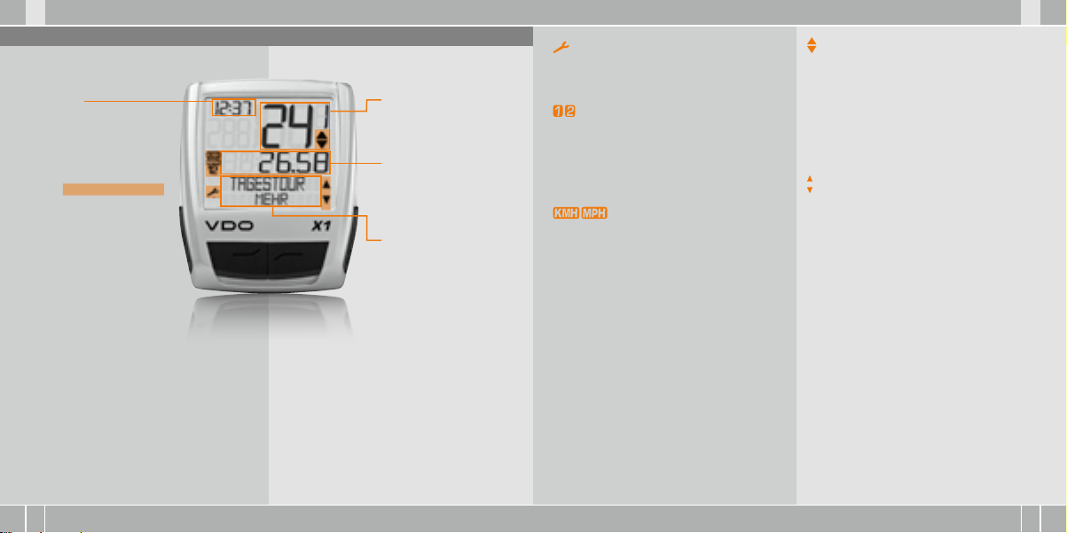
1. Display
Das Di splay kann ma n in
4 Segme nte glieder n:
Segme nt 1
Zeigt im mer die
aktu elle Uhrzei t.
Zusät zlich finde n Sie im
Display Indikator-Elemente.
Die Beschreibung der einzelnen
Indikatoren finden Sie auf der
rechten Seite.
Segme nt 2
Zeigt die aktuelle
Geschwindigkeit.
Segme nt 3
Zeigt den Wert der von
Ihnen gewählten AnzeigeFunktion/Information.
Segme nt 4
Zeigt in der oberen Zeile
(Info-Zeile) die Bezeichnung
der gewählten Funktion.
In der zweiten Zeile (MenüZeile) wird angezeigt,
B
ob es weitere Informati-
onen gibt „MEHR“
B
ob es eine weitere
Auswahlmöglichkeit
gibt „AUSWAHL“
Serv ice Indikat or
Zeigt an, dass Ihr Fahrrad zum Service sollte.
Das Service-Intervall können Sie für Rad 1 und Rad 2
individuell festlegen.
Indika tor Rad 1/ Rad 2
Der Computer kann mit zwei verschiedenen Einstellungen für 2 Fahrräder arbeiten. Der Indikator
zeigt an, welches der beiden Fahrräder Sie zur
Nutzung ausgewählt haben. Die Gesamtkilometer werden entsprechend für Rad 1 und für Rad 2
getrennt gezählt und gespeichert.
Me sseinheit ( KMH oder MPH)
Der Computer kann sowohl KMH als auch MPH
anzeigen. Strecken werden entsprechend in Kilometer oder Meilen angezeigt. Der Indikator zeigt
die gewählte Messeinheit an.
Abweic hungsindi kator Gesc hwindigkei t
(akt uell) zu Gesc hwindigkei t (Schnitt)
Der Computer vergleicht die aktuelle Geschwindigkeit mit der Durchschnittsgeschwindigkeit.
Der Indikator zeigt an
B
ob die aktuelle Geschwindigkeit über dem
Durchschnitt liegt (+1 km/h)
B
unter dem Durchschnitt liegt (-1 km/h)
B
oder dem Durchschnitt entspricht
(Toleranz +/- 1 km/h)
Menus teuerungs indikato r
Wenn ein Untermenu aufgerufen wurde, blinken
diese Indikatoren und zeigen an, dass es noch
weitere Auswahlmöglichkeiten gibt oder der Computer auf eine Eingabe wartet (Einstell-Modus).
Page 4
X1 VDO CYCLECOMPUTING6
D GB F I
I F GB D
www.vdocyclecomputing.com X1 7
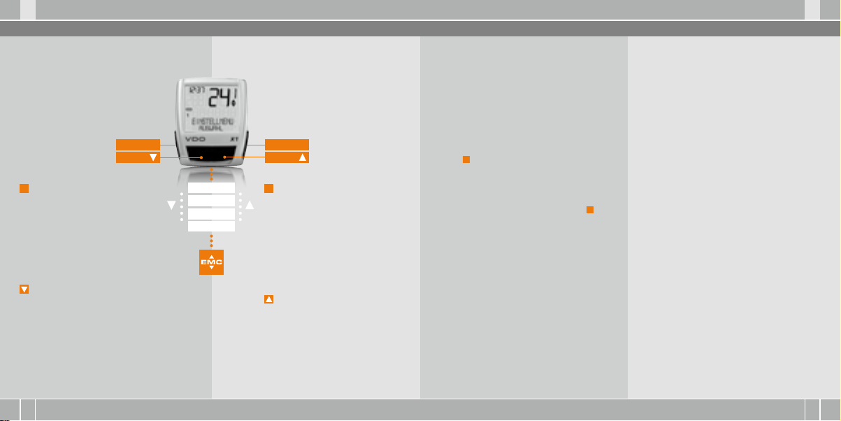
2. Bedienung
Für die einfache Bedienung Ihres Computers haben
wir das EMC = Easy Menu Control System entwickelt.
Das EMC erleichtert die Bedienung des Computers
über eine Volltext-Menüführung wie sie
bei den meisten Handys verwendet wird.
C = CLEAR
DOWN
C
= CLEAR
Im Funktions-Modus:
B
Vom Untermenü eine Menüebene
zurück springen.
Im Einst ell-Mod us:
B
Zurückspringen
zu Funktions-Modus.
B
Eine Eingabe korrigieren.
B
Eine Ziffer zurückspringen.
= DOWN
Im Funkt ions-Mo dus:
B
Innerhalb der Funktionen
abwärts blättern.
Im Einst ell-Mod us:
B
Innerhalb der Einstell-Modi
abwärts blättern.
B
Eine Ziffer verringern.
Menü-Indikatoren im Display zeigen durch Blinken
an, dass es weitere Auswahlmöglichkeiten gibt. Im
Funktions-Modus und im Einstell-Modus erfolgt
die Bedienung über die 4 Tasten.
M = MENU
UP
FUNKTION 3
FUNKTION 4
FUNKTION 5
FUNKTION 6
M
= MENU
Im Funkt ions-Mo dus:
B
Verfügbares Untermenü aufrufen.
B
Auswahl bestätigen.
Sie erkennen ein Untermenü durch
die blinkenden Menü-Indikatoren.
Im Einst ell-Mod us:
B
Eine Einstellung auswählen.
B
Eine gemachte Einstellung bestätigen.
B
Eine getroffene Auswahl bestätigen.
= UP
Im Funkt ions-Mo dus:
B
Innerhalb der Funktionen
aufwärts blättern.
Im Einst ell-Mod us:
B
Innerhalb der Einstell-Modi
aufwärts blättern.
B
Eine Ziffer erhöhen.
3. Informations-Funktionen
TAGESTOUR
Zeigt die Strecke der aktuellen Tour seit dem letzten
Reset. Maximalwert 999,99 km.
Bei Überschreiten des Maximalwertes beginnt der
Zähler wieder bei Null. Gleichzeitig werden die
Werte für Fahrzeit und Durchschnittsgeschwindigkeit auf Null zurückgesetzt.
TAGESTOUR/MEHR
MEHR zeigt an, dass es zum Hauptmenu TAGESTOUR ein Untermenu gibt. Das Untermenu öffnen
Sie mit M. Im Untermenu finden Sie:
B
Gesamtkilometer RAD 1 bis max. 99.999 km
B
Gesamtkilometer RAD 2 bis max. 99.999 km
B
Totalkilometer Summe für Rad 1 + Rad 2
bis max. 199.999 km
Das Untermenu verlassen Sie wieder mit C.
FAHRZE IT
Zeigt die Fahrzeit der aktuellen Tagestour seit
dem letzten Reset. Maximal 23:59:59 HH:MM:SS.
Bei überschreiten des Maximalwertes beginnt die
Fahrzeit-Messung bei Null. Gleichzeitig werden
Tagestour und Durchschnittsgeschwindigkeit auf
Null zurückgestellt.
DSCHN GS CHW
Zeigt die Durchschnittsgeschwindigkeit, berechnet
aus Tagestour und Fahrzeit, seit dem letzten Reset.
Genauigkeit: 2 Kommastellen.
Die Durchschnittsgeschwindigkeit wird neu berechnet, wenn die Tagestour oder die Fahrzeit den
Maximalwert übersteigt.
MAX G SCHW
Zeigt die Maximalgeschwindigkeit auf der aktuellen
Tour seit dem letzten Reset. Genauigkeit: 2 Kommastellen.
Page 5

X1 VDO CYCLECOMPUTING8
D GB F I
I F GB D
www.vdocyclecomputing.com X1 9
4 Installation
4.1 Montage von Sensor, Magnet und Lenkerhalterung >>> P01
Bei Federgabelmontage unbedingt den Federweg
der Gabel beachten. Das Kabel benötigt entsprechendes Spiel.
ACHTUN G: Kabelriss gefahr.
step 1 Legen sie das Unterleg-Gummi unter den
Sensor. Montieren Sie den Sensor auf der Gabelseite, an der Sie später den Computer am Lenker
montieren wollen (rechts oder links) mit beiliegendem Kabelbinder (zunächst lose, noch nicht
festziehen). Der Sensor kann je nach Platzverhältnissen vorne auf die Gabel, innen an der Gabel oder hinten an der Gabel, montiert werden.
>>> P02
step 2 Speichenmagnet um eine Außen-Speiche
legen. Der silberne Magnetkern zeigt dabei zum
Sensor. Magnet an der Sensor- Markierung mit
etwa 1 - 5 mm Abstand ausrichten.
step 3 Sensor und Magnet endgültig ausrichten
und fixieren: Kabelbinder festziehen und Magnet
kräftig zudrücken.
step 4 Kabel vom bereits montiertem Sensor am
Bremskabel entlang zum Lenker verlegen (mit
beiliegendem Kabelbinder fixieren. Ideal: Sensorkabel um das Bremskabel hochwendeln.
step 5 Entscheiden ob Lenker-oder Vorbau-Montage, entsprechend den Fuß der Lenkerhalterung
um 90° drehen. Dazu die Schrauben in der Halterung lösen, Fuß herausnehmen und um 90° drehen, einsetzen und Schrauben wieder festdrehen.
ACHTUNG: Schr auben nicht übe rdrehen.
step 6 Kabelbinder durch die Schlitze in der Lenkerhalterung führen, um den Lenker oder den Vorbau legen und anziehen (noch nicht festziehen).
step 7 Bei Lenkermontage: Neigungswinkel des
Computers ausrichten, um optimale Ablesbarkeit
zu erreichen. Kabelbinder jetzt festziehen.
Überstehende Enden mit Zange abknipsen.
4.2 Batterieeinbau in den Computer >>> P03
Ihr VDO Computer wird mit einer 3V Batterie
(Type 2032) geliefert. Die Bat terie ist im Li efer-
statu s bereits e ingebaut . Zum Batteriewechsel
gehen Sie folgendermaßen vor:
step 1 Legen Sie die Batterie mit dem +Pol nach
oben in das Computergehäuse ein.
step 2 Achten Sie darauf, dass sich die Batterie
nicht verkantet.
step 3 Beachten Sie, dass die Gummidichtung
glatt auf dem Batteriefachdeckel aufliegt.
step 4 Setzen Sie den Batteriefachdeckel in die
Öffnung ein und drehen Sie ihn mit einem Geldstück
nach rechts bis zum Anschlag fest
(ca. ⅓ Umdrehung).
TIPP zum B atteriewe chsel: VDO empfie hlt einen
jährli chen Batter iewechsel . Kaufen Sie re chtzeiti g
eine neu e Batterie, um e ine einwandfr eie Funktion sicher zustellen .
Beim Ba tteriewec hsel werden al le Grundeinstellung en des Computer s auf Werksein stellung
zurück gesetzt . Notieren Sie d eshalb unbedi ngt
vor dem Ent nehmen der alte n Batterie di e eingegebe nen Radgröße n sowie die bisher g efahrenen Ge samtkilom eter für Ihr Rad 1 und R ad 2.
Progra mmieren Sie die se nach dem Einse tzen
der neue n Batterie wi eder ein.
4.3 Einsetzen des Computers in die Lenkerhalterung >>> P04
Das VDO Twist-Click-System verbindet den Computer
sicher mit der Lenkerhalterung.
step 1 Computer in 10 Uhr-Position in die Halterung einsetzen.
step 2 Computer nach rechts auf 12-Uhr-Position
drehen „twist“ und in das Haltesystem einrasten
„click“.
step 3 Zum Herausnehmen den Computer nach
links drehen (dabei nicht drücken oder ziehen).
Gedankenstütze: Rein nach Rechts, Los nach Links
Page 6
X1 VDO CYCLECOMPUTING10
D GB F I
I F GB D
www.vdocyclecomputing.com X1 11
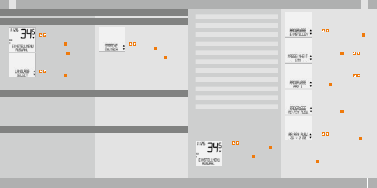
5. Grundeinstellungen
5.1 Sprache einstellen
Gehen Sie mit den
-Tasten zu
EINSTELLMENU/AUSWAHL.
Bestätigen mit
Sie befinden sich jetzt im Einstell-Modus (mit
den kommen Sie zurück in den
Funktions-Modus).
zu LANGUAGE SELECT.
Bestätigen mit M.
M
.
C
– 3 Sekun-
5.2 Einstellen und Messen der Radgröße
Damit Ihr VDO Computer korrekt messen kann,
müssen Sie die Radgröße (Radabrollumfang) Ihres
Rades einstellen. Hier gibt es 2 Möglichkeiten:
zu SPRACHE DEUTSCH.
Bestätigen mit M.
DEUTSCH AUSWAHL OK? Bestätigen mit M.
Rückmeldung des Computers: SPRACHE AUSW
FERTIG. Der Computer kehrt automatisch zum
Ausgangsmenu EINSTELLMENU/AUSWAHL zurück.
16 x 1,7 5 1272 50,1
20 x 1,7 5 1590 62,6
24 x 1 ⅜ 1948 76,7
24 x 1, 75 1907 75,1
26 x 1 1973 77,7
26 x 1,5 2026 79,8
26 x 1,6 2051 80,7
26 x 1,7 5 2070 81,5
26 x 1,9 2089 82,2
26 x 2,0 0 2114 83,2
26 x 2, 125 2133 84,0
26 x 1 ⅜ 2105 82,9
26 x ¾ 1954 76,9
27 x 1 ¼ 2199 86,6
28 x 1,5 2224 87,6
28 x 1, 75 2268 89,3
28 x 1 ½ 2265 89,2
28 x 1 ⅜ 2205 86,8
30-622 2149 84,6
32-622 2174 85,6
37-62 2 2205 86,8
40-622 2224 87,6
mm-Wert inch-Wert
Mit
zu RADGRÖSSE/
EINSTELLEN. Bestätigen mit M.
MASSEINHEIT/KMH.
Bestätigen mit M oder
zum Wechsel zu MPH.
RADGRÖSSE/RAD 1 (mit zur
Einstellung für Rad 2). Bestätigen mit M.
RADGRÖSSE/REIFEN AUSW.
Bestätigen mit M.
5.2.1 Einstellen über Reifentabelle
In der Reifentabelle sind die gängigen Reifentypen
aufgeführt. Wenn Ihr Reifentyp nicht aufgeführt
ist, empfehlen wir die manuelle Eingabe der Radgröße. Die in der Tabelle genannten Werte sind
Näherungswerte.
Diese Werte weichen je nach Reifen-Marke,
Reifenhöhe und Reifenprofil ab. Es kann daher
auch zu Abweichungen der gemessenen Strecke
und der angezeigten Geschwindigkeit kommen.
So stel len Sie die Reif engröße üb er Auswahl
des Rei fens ein:
Mit zu EINSTELLMENU/
AUSWAHL. Bestätigen mit M.
Sie befinden sich jetzt im Einstell-Modus (mit C – 3 Sekunden kommen Sie zurück in den
Funktions-Modus).
REIFEN AUSW./WÄHLEN.
Mit wählen Sie jetzt Ihren
Reifen aus. Bestätigen mit M.
Es erscheint die Kontrollabfrage: „Reifengröße“/
AUSWAHL OK? Wenn die angezeigte Reifengröße
mit der von Ihnen gewünschten übereinstimmt,
bestätigen Sie mit M.
Das Display bestätigt RADGRÖSSE/SET FERTIG.
Automatische Rückkehr zu EINSTELLMENU/AUSWAHL.
Page 7

X1 VDO CYCLECOMPUTING12
D GB F I
I F GB D
www.vdocyclecomputing.com X1 13
5.2.2 Einstellen über Radumfang >>> P05
Für die manuelle Eingabe der Radgröße müssen Sie
zunächst den Radabrollumfang Ihres Rades messen.
Messe n der Radab rollumfän ge:
step 1 Ventil des Vorderrades genau senkrecht
zum Boden ausrichten.
step 2 Diese Stelle am Boden mit einem Strich
(z.B. Kreide) markieren.
step 3 Das Rad eine Radumdrehung nach vorn
schieben, bis das Ventil erneut senkrecht zum
Boden steht.
step 4 Diese Stelle ebenfalls am Boden markieren.
step 5 Den Abstand zwischen den beiden Markie-
rungen messen. Das ist Ihr Radumfang (=AbrollUmfang).
step 6 Geben Sie den so gemessenen Radumfang
in Ihren VDO-Computer ein.
ACHTUN G: Wenn Sie KMH– Anzeige gewä hlt
haben , müssen Sie den Ra dumfang in mm ein geben (B ei gewählter M PH-Anzei ge geben Sie
den Radum fang in inch ein).
So stel len Sie manue ll die Radgr öße ein:
Mit zu EINSTELLMENU/
AUSWAHL. Bestätigen mit M.
Sie befinden sich jetzt im
Einstell-Modus (mit C –
3 Sekunden kommen Sie
zurück zum Funktions-Modus).
Mit zu RADGRÖSSE/EINSTELLEN. Bestätigen mit M.
MASSEINHEIT/KMH. Bestätigen
mit M oder zum Wechsel
zu MPH.
RADGRÖSSE/ RAD 1
(mit zur Einstellung für Rad 2).
Bestätigen mit M.
Mit zu RADGRÖSSE/
MANUELL SET. Bestätigen mit M.
RAD 1 …SET UMFANG/WEITER
Mit stellen Sie jetzt den
gemessenen Radabrollumfang
ein. Bestätigen Sie die Eingabe
mit M.
RAD 1/SET OK? Bestätigen mit M.
Das Display bestätigt: RADGRÖSSE/SET FERTIG
Automatische Rückkehr zu EINSTELLMENU/
AUSWAHL.
5.3 Einstellen Uhr
So stel len Sie die Uhr ei n:
Mit zu EINSTELLMENU/
AUSWAHL Bestätigen mit M.
Sie befinden sich jetzt im Einstell-Modus (mit C – 3 Sekunden kommen Sie zurück zum
Funktions-Modus).
Mit zu UHR/EINSTELLEN
Bestätigen mit M.
UHR/24-H-ANZEIGE (mit
können Sie umstellen auf
12-H-Anzeige). Bestätigen mit M.
Achtung : Die Werksein stellungen bet ragen für
Rad 1 = 215 5 mm und für Rad 2 = 200 0 mm. Wenn
Sie keine R adgrößen eing eben, arbe itet der
Computer m it diesen Werk seinstellunge n. Die so
gemess enen Werte fü r Geschwindigke it, Strecke
etc. könn en deutlich v on den tats ächlichen We rten
abweichen.
UHR…SET STUNDEN/WEITER
Mit stellen Sie die Stunden ein. Bestätigen Sie die
Stundeneinstellung mit M.
UHR…SET MINUTEN/WEITER
Mit stellen Sie die Minuten ein. Bestätigen Sie die
Minuten-Einstellung mit M.
UHR/SET OK? Bestätigen Sie mit M.
Das Display bestätigt: UHR SET FERTIG. Automatische Rückkehr zu EINSTELLMENU/AUSWAHL.
Page 8

X1 VDO CYCLECOMPUTING14
D GB F I
I F GB D
www.vdocyclecomputing.com X1 15
5.4 Einstellen Gesamtkilometer
Sie können die Werte der Streckenzähler jederzeit
(z.B. am Ende einer Saison) programmieren.
Mit zu EINSTELLMENU/
AUSWAHL. Bestätigen mit M.
Sie befinden sich jetzt im Einstell-Modus (mit C – 3 Sekunden kommen Sie zurück zum
Funktions-Modus).
Mit zu KM ZÄHLER/EINSTELLEN. Bestätigen mit M.
KM RAD 1/SET OK? Bestätigen mit M.
Das Display bestätigt KM RAD 1 /SET FERTIG.
Automatische Rückkehr zu EINSTELLMENU/
AUSWAHL.
KM ZÄHLER/RAD 1 (mit
kommen Sie zur Einstellung für
RAD 2). Bestätigen mit M.
KM RAD 1… EING STRECKE/WEITER
Die blinkende Ziffer können Sie
mit einstellen. Zum Aufruf
der nächsten Ziffer bestätigen
Sie mit M. Wiederholen Sie die
Schritte, bis die letzte, rechte
Ziffer blinkt. Bestätigen mit M.
5.5 Umschalten von Rad 1 auf Rad 2
Ihr VDO Computer kann an 2 Fahrrädern verwendet werden. Wenn Sie von Rad 1 auf Rad 2 wechseln, müssen Sie den Computer vor der Fahrt auf
das benutzte Rad einstellen:
Mit zu EINSTELLMENU/
AUSWAHL. Bestätigen mit M.
Sie befinden sich jetzt im Einstell-Modus (mit C – 3 Sekunden
kommen Sie zurück zum Funktions-Modus).
Mit zu RAD / AUSWAHL.
Bestätigen mit M.
RAD 1 (mit stellen Sie um
auf RAD 2). Bestätigen mit M.
RAD 1/AUSWAHL OK? Bestätigen mit M.
Das Display bestätigt RAD/AUSW FERTIG. Automatische Rückkehr zu EINSTELLMENU/AUSWAHL
Das ausgewählte Rad 1 oder 2
wird im Display unten links ( )
angezeigt.
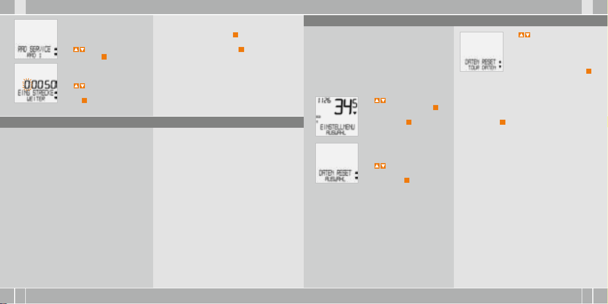
5.6 Service-Intervall-Anzeige
Die VDO Service-Intervall-Anzeige erinnert Sie daran,
Ihr Rad in der Werkstatt überprüfen zu lassen.
Sie können das Service-Intervall EIN- oder AUSschalten. Sie können individuelle Service-Intervalle
für 2 Räder einstellen. Wenn die eingestellte
Service-Intervall-Strecke gefahren wurde:
B
Blinkt das -Symbol im Display auf.
B
In der Informationszeile erscheint
RAD SERVICE/RAD 1
Jetzt sollten Sie den empfohlenen Radcheck entweder selbst durchführen oder Ihr Rad vom Fachhändler checken lassen.
Drücken Sie eine beliebige Taste. Der Text RAD SERVICE verschwindet wieder. Nach weiteren 50 km
erlischt auch das -Symbol wieder. Sie können
das blinkende -Symbol auch abschalten. Geben
Sie dazu das Service-Intervall erneut ein.
ACHTUN G, wichtiger Hi nweis: Beim We chsel von
Rad 1 auf 2 od er umgekehrt w erden die Daten
Tagestour, Fah rzeit, Dur chschnittsg eschw. und
Max- Geschw. für di e letzte Tour auf Nu ll gestellt.
So stel len Sie die Ser vice-I ntervall e ein:
Mit zu EINSTELLMENU/
AUSWAHL. Bestätigen mit M.
Sie befinden sich jetzt im Einstell-Modus (mit C – 3 Sekunden
kommen Sie zurück zum Funktions-Modus).
Mit zu RADSERVICE/
EINSTELLEN. Bestätigen mit M.
RADSERVICE/EIN (mit schalten
Sie auf AUS). Bestätigen mit M.
Page 9
X1 VDO CYCLECOMPUTING16
D GB F I
I F GB D
www.vdocyclecomputing.com X1 17
RAD SERVICE/RAD 1.
Mit wechseln Sie zu RAD 2.
Bestätigen mit M.
RAD 1…EING STRECKE.
Die blinkende Ziffer können Sie
mit einstellen. Zum Aufruf
der nächsten Ziffer bestätigen
Sie mit M.
Wiederholen Sie die Schritte, bis die letzte, rechte
Ziffer blinkt. Bestätigen mit M.
RAD 1/SET OK? Bestätigen mit M.
Das Display bestätigt: RADSERVICE/SET FERTIG.
Automatische Rückkehr zu EINSTELLMENU/
AUSWAHL.
5.7 Sleep-Modus
Ihr VDO-Computer ist mit einer Sleep-Modus
Funktion ausgestattet. Im Sleep-Modus wird ein
Großteil des Displays ausgeschaltet, um Batterieleistung zu sparen. Uhrzeit und Service-Intervall
Anzeige werden weiter angezeigt.
Der Sleep-Modus (Uhr wird angezeigt) schaltet
sich ein, wenn 5 min. lang keine Geschwindigkeitsimpulse verarbeitet werden und keine Taste betätigt wurde.
Der Sleep-Modus wird beendet, wenn wieder Geschwindigkeitsimpulse verarbeitet werden (beim
Fahren) oder eine Taste betätigt wird.
5.8 Reset-Funktionen
Mit der RESET Funktion stellen Sie wahlweise zurück
B
TOUR DATEN
B
TOTAL KM
Bei den jeweiligen Reset-Modi werden folgende
Informationen gelöscht:
B
TOUR DATEN: Tagestour, Fahrzeit,
Durchschnitts geschw., Max-Geschw.
B
TOTAL KM: Gesamt km, km Rad 1, km Rad 2
Mit
zu EINSTELLMENU/
AUSWAHL. Bestätigen mit
Sie befinden sich jetzt im Einstell-Modus (mit
kommen Sie zurück zum Funktions-Modus).
Mit zu
DATEN RESET/AUSWAHL.
Bestätigen mit
C
– 3 Sekunden
M
.
M
.
Mit zu den Daten, die Sie
zurückstellen wollen:
B
DATEN RESET/TOUR DATEN
ODER
B
TOTAL KM
Bestätigen Sie Ihre Auswahl mit M.
Abfrage. AUSWAHL/RESET?
ACHTUN G: Dieser Schr itt kann nicht r ückgängig
gemacht w erden.
Bestätigen mit M, nur wenn Sie die ausgewählten
Daten löschen wollen. Das Display bestätigt:
DATEN RESET/RESET FERTIG. Automatische Rückkehr zu EINSTELLMENU/AUSWAHL.
Page 10

X1 VDO CYCLECOMPUTING18
D GB F I
I F GB D
www.vdocyclecomputing.com X1 19
6. Garantiebedingungen
VDO Cycle Parts gewährt für Ihren VDO-Computer
eine Garantie von 5 Jahren ab Kaufdatum. Die
Garantie erstreckt sich auf Material- und Verarbeitungsfehler am Computer selbst, am Sensor/
Sender und an der Lenkerhalterung. Kabel und
Batterien sowie Montagematerialien sind von
der Garantie ausgeschlossen. Die Garantie ist
nur dann gültig, wenn die betroffenen Teile nicht
geöffnet wurden (Ausnahme: Batteriefach des
Computers), keine Gewalt angewendet wurde und
keine mutwillige Beschädigung vorliegt.
Bitte bewahren Sie den Kaufbeleg sorgfältig auf,
da er im Reklamationsfall vorgelegt werden muss.
Bei einer berechtigten Reklamation erhalten Sie
von uns ein vergleichbares Austauschgerät. Ein
Anspruch auf Ersatz des identischen Modells
besteht nicht, wenn durch Modellwechsel die
Produktion des reklamierten Modells eingestellt
wurde.
Bitte wenden Sie sich mit allen Reklamationen
und Garantieansprüchen an Ihren Fachhändler,
bei dem Sie das Gerät gekauft haben. Oder senden
Sie Ihre Reklamation direkt an:
Cycle Pa rts GmbH
Große Ahlmühle 33
D-76865 Rohrbach (Germany)
Für technische Fragen stehen wir Ihnen jederzeit
unter folgender Hotline zur Verfügung:
+49 (0) 6 3 49 - 96 35 - 10.
Weitere technischen Informationen erhalten Sie
unter: www.vdocyclecomputing.com
Im Zuge der Weiterentwicklung behalten wir uns
technische Änderungen vor.
7. Technische Spezifikationen
Comput er:
ca. 45 x 52 x 16 mm, Gewicht: ca. 45 g
Lenkerhalterung:
Gewicht: ca. 15 g
Senso r: Gewicht ca. 20 g
Batte rie Compute r:
3V, Type 2032
Batte rie Lebens dauer:
1200 Fahr-Stunden, ca.. 24.000 km (15.000 M)
Arbei ts-Tempera tur des Displ ays:
-15 °C to +60 °C
Gesch windigkeit s-Berei ch:
bei Radgröße 2155 mm, min 2.5 km/h,
max 199.5 km/h
Fahrze it Messber eich:
bis 23:59:59 HH:MM:SS
Tagest our-Zähle r Messbere ich:
bis 999,99 km oder mi
Gesa mt-KM 1 u. 2 Mes sbereich :
bis 99.999 km oder mi
Total Kil ometer Mes sbereich :
bis 199.999 km or mi
Radum fang Einste llbereich :
von 100 mm bis 3999 mm (3,9 bis 157,4 inch)
8. Fehlerbehebung
Hier finden Sie eine Liste möglicher Fehler, ihrer Ursachen und was Sie dagegen tun können:
Fehler Mög liche Ursa che Behebung
Halbe Segmente in der Anzeige
(z.B. nach einem Batteriewechsel)
Keine Geschwindigkeits-Anzeige Abstand von Sensor zu Magnet
Keine Geschwindigkeits-Anzeige Computerkopf nicht korrekt
Keine Geschwindigkeits-Anzeige Radumfang ist nicht korrekt
Anzeige wird schwach Batterie leer Batterie prüfen, evtl. ersetzen
Anzeige wird schwach Temperaturen unter 5° machen
Computer-Software läuft nach
Batteriewechsel nicht korrekt
zu groß
in der Lenkerhalterung
eingerastet
eingestellt oder steht auf Null
die Anzeige träge
Batterie herausnehmen
und neu einsetzen
Position von Sensor und
Magnet korrigieren
Computerkopf in die Lenkerhalterung setzen, bis zum
Anschlag („click“) drehen
Radumfang einstellen
Bei normalen Temperaturen
arbeitet die Anzeige wieder
normal
Page 11

X1 VDO CYCLECOMPUTING20
F I
I F
www.vdocyclecomputing.com X1 21
Preface
Congratulations
With your selection of a VDO computer you have opted for a technically very high quality appliance.
In order to fully benefit from the potential of the computer, we recommend that you carefully read this
manual. It contains all operating instructions and many other useful tips.
We hope you enjoy cycling with your VDO bike computer.
Cycle Parts GmbH
Pack contents
Please first check that this pack is complete:
1 VDO computer
Battery installed
1 universal handlebar holder
with cable and sensor
Table of contents
1. Display 22
2. Operation 24
3. Information functions 25
4. Installation 26
4.1 Fitting the sensor, magnet
and handlebar holder 26
4.2 Installing the battery in the computer 27
4.3 Placing the computer into
the handlebar holder 27
5. Basic settings 28
5.1 Setting the language 28
5.2 Setting and measuring the wheel size 28
5.2.1 Select from tyre table 28
5.2.2 Setting using wheel circumference 30
5.3 Setting the CLOCK 31
5.4 Setting the total kilometres 32
5.5 Switch from Bike1 to Bike2 32
5.6 Service interval display
5.7 Sleep mode 34
5.8 Reset functions 35
6. Terms of guarantee 36
7. Technical spezifications 36
8. Troubleshooting 37
33
DGBD GB
1 rubber pad
for sensor
1 spoke magnet
(clip magnet)
cable ties
for fitting the holder
and sensor
„>>> P02“ links at the beginning of a chapter
are related to the respective picture in the
picture book!
Page 12

X1 VDO CYCLECOMPUTING22
F I
I F
www.vdocyclecomputing.com X1 23
1. Display
The dis play can be div ided
into 4 se ctions:
Sect ion 1
alway s shows
the cur rent time.
You will also find
indicator elements
on the di splay
You can find the description
of the individual indicators on
the right hand side.
Sect ion 2
shows the
current speed.
Sect ion 3
shows the value of the
display function/
information that you
selected.
Sect ion 4
shows the description of
the selected function in
the top line (info line). The
second line (menu line)
shows,
B
whether there is more
information „MORE“
B
whether there is
another selection
option „SELECT“
Serv ice indicat or
shows that your bike should go for a service.
You can set the service interval individually for
bike 1 and bike 2
Indica tor bike 1/ bike 2
The computer can work with two different settings for 2 bikes. The indicator shows which of the
two bikes you have chosen to use.
The total distances are accordingly counted and
stored separately for bike 1 and bike 2.
Mea suremen t unit (KMH or MPH)
The computer can display both KHM and MPH.
Distances are shown in kilometres or miles
accordingly.The indicator shows the selected
measurement unit
Speed d ifferenc e indicator ( current)
to spee d (average)
The computer compares the current speed
with the average speed.
The indicator shows
B
whether the current speed is higher than
the average (+1 KMH)
B
below the average (-1 KMH)
B
or matches the average
(tolerance +/- 1 KMH).
Menu pr ompt indica tor
When a submenu has been accessed, these indicators flash and show that there are other selection options or that the computer is waiting for
an entry (setting mode).
DGBD GB
Page 13

X1 VDO CYCLECOMPUTING24
F I
I F
www.vdocyclecomputing.com X1 25
2. Operation
To make your computer easy to use, we have developed the EMC Easy Menu Control system.
The EMC makes your computer easier to operate
by means of a full text menu guidance,
as is used on most mobile phones.
C = CLEAR
DOWN
C
= CLEAR
In func tion mode:
B
Jump back a menu level from
the submenu.
In sett ing mode:
B
Jump back to function mode.
B
Correct an entry.
B
Jump back a digit.
= DOWN
In func tion mode:
B
Scroll downwards within
the functions.
In sett ing mode:
B
Scroll downwards within
the setting modes.
B
Decrease a digit.
Menu indicators on the display flash to show that
there are other selection options.
In function mode and setting mode, the computer is
operated using the 4 buttons.
M = MENU
UP
FUNCTION 3
FUNCTION 4
FUNCTION 5
FUNCTION 6
M
= MENU
In func tion mode:
B
Access available submenu.
B
Confirm selection.
You can recognise a submenu by
the flashing menu indicators.
In sett ing mode:
B
Select a setting.
B
Confirm a setting.
B
Confirm a selection made.
= UP
In func tion mode:
B
Scroll upwards within
the functions
In sett ing mode:
B
Scroll upwards within
the setting modes.
B
Increase a digit.
3. Information functions in function mode
TRIPDISTANCE
Shows the distance of the current trip since the
last reset.Maximum value 999.99 km.
If the maximum value is exceeded, the counter
starts again at zero. At the same time the values for
ride time and average speed are set back to zero
TRIPDISTANCE/MORE
MORE shows that there is a submenu for the main
menu TRIPDISTANCE. You open the submenu with
the M button. In the submenu you will find:
B
Total kilometres BIKE 1 ODO BIKE 1 up to a
maximum of 99,999 km.
B
Total kilometres BIKE 2 ODO BIKE 2 up to a
maximum of 99,999 km.
B
Total kilometres for Bike 1 + Bike 2 ODO TOTAL
up to a maximum of 199,999 km.
You leave the submenu by pressing C again.
RIDE TIM E
Shows the ride time of the current day‘s trip since
the last reset. Maximum 23:59:59 HH:MM:SS
If the maximum value is exceeded, the ride time
measurement starts again at zero. At the same
time the day‘s tripdistance and average speed are
set back to zero.
AVG SPEED
Shows the average speed, calculated from the
day‘s tripdistance and ride time, since the last reset
Accuracy: 2 decimal places.
The average speed is recalculated if the day‘s tripdistance or ride time exceeds the maximum value.
MAX S PEED
Shows the maximum speed on the current trip since
the last reset. Accuracy: 2 decimal places.
DGBD GB
Page 14

X1 VDO CYCLECOMPUTING26
F I
I F
www.vdocyclecomputing.com X1 27
4 Installation
4.1 Fitting the sensor, magnet and handlebar holder >>> P01
When fitting to suspension forks, it is essential
to bear in mind the spring deflection of the
forks. The cable requires an appropriate amount
of play.
ATTENT ION: Risk of broke n cable.
Step 1 Place the rubber pad unde r the sensor.
Fit the sensor on the same side of the fork where
you later want to fit the computer to the handlebars (right or left) using the c able ties supplied
(loose at first, do not pull tight just yet).
Depending on the room available, the sensor can
be fitted at the front of the for k, inner side of the
fork or backside of the forks. >>> P02
Step 2 Place spoke magnet around an outer
spoke. The s ilver middle of the magnet points
towards the sensor. Align the magnet to the
sensor mark with a gap of about 1 - 5 mm.
Step 3 Align sensor and magnet f or good and
fasten in pl ace: Pull cable ties tight and push
magnet in firmly.
Step 4 Install cable from sensor already fitted
along brake cable to the handlebars (fasten with
cable ties s upplied) Ideally: Co il sensor cable up
around the b rake cable.
Step 5 Decid e whether fitting to handlebar or
stem and turn the base of the handlebar holder
by 90° accor dingly. To do so, un do the screws in
the holder, take out the foot and turn it 90°, insert and tighten the screws again.
ATTENTION: Do not over t ighten screws .
Step 6 Guide the cable ties thro ugh the slot in
the handlebar holder, place around the handle
bars or the stem and pull (do not pull tight just
yet).
Step 7 If fitting to handlebars: Align computer
angle to achieve optimum readability. Now pull
cable ties t ight. Snip off protr uding ends with
clippers.
4.2 Installing the battery in the computer >>> P03
Your VDO computer is supplied with a 3V battery
(type 2032). The bat tery is alr eady insta lled
when sup plied. To change the battery, proceed
as follows:
step 1 Place the battery in the computer casing
with the +terminal facing up.
Step 2 Make sure that the battery does not
get wedged.
step 3 Take care that the rubber seal lies flat on
the battery compartment lid.
Step 4 Insert the battery compartment lid into the
opening and turn it with a coin to the right as far
as it will go (approx. 1/3 turn).
TIP for ch anging batte ry: VDO r ecommends cha nging the ba ttery once a y ear. Buy a new bat tery in
good time to ensure the function works perfectly.
When the b attery is cha nged, all ba sic computer sett ings are rese t to factory set tings. Bef ore
removing the old batter y, it is therefore essent ial
to note dow n the wheel size s entered and th e
total ki lometres cy cled so far for y our bike 1 and
bike 2. Pr ogram these in a gain after ins erting the
new bat tery.
4.4 Placing the computer into the handlebar holder >>> P04
The VDO twist-click system fastens the computer
securely with the handlebar holder.
Step 1 Place computer into the holder in 10 o’clock
position.
Step 2 Twist computer to the right to 12 o’clock position and click into the holder system.
Step 3 To take the computer out, twist to the left
(do not push or pull).
How to remember: Rigid to the Right, Loose to the Left
DGBD GB
Page 15

X1 VDO CYCLECOMPUTING28
www.vdocyclecomputing.com X1 29
5. Basic settings
5.1 Setting the language
Using the buttons, go to
SETTINGS/SELECT.
Confirm with M.
You are now in setting mode
(pressing C for 3 seconds gets
you back to function mode).
to LANGUAGE SELECT.
Confirm with M.
ENGLISH SELECT OK? Confirm with M.
LANGUAGE SELECT DONE. The computer automatically returns to the start menu SETTINGS/SELECT.
to LANGUAGE ENGLISH.
Confirm with M.
5.2 Setting and measuring the wheel size
You must set the wheel size (wheel roll circumference) of your bike so that your VDO computer
can measure correctly.
There are 2 ways of doing this:
5.2.1 Setting using tyre table
The common types of tyres are listed in the tyre
table. If your tyre type is not listed, we recommend
entering the wheel size manually.
The values given in the table are approximate
values. These values differ according to brand, tyre
height and tyre profile. This can consequently also
lead to discrepancies in the distance measured
and the speed shown.
16 x 1,7 5 1272 50,1
20 x 1,7 5 1590 62,6
24 x 1 ⅜ 1948 76,7
24 x 1, 75 1907 75,1
26 x 1 1973 77,7
26 x 1,5 2026 79,8
26 x 1,6 2051 80,7
26 x 1,7 5 2070 81,5
26 x 1,9 2089 82,2
26 x 2,0 0 2114 83,2
26 x 2, 125 2133 84,0
26 x 1 ⅜ 2105 82,9
26 x ¾ 1954 76,9
27 x 1 ¼ 2199 86,6
28 x 1,5 2224 87,6
28 x 1, 75 2268 89,3
28 x 1 ½ 2265 89,2
28 x 1 ⅜ 2205 86,8
30-622 2149 84,6
32-622 2174 85,6
37-62 2 2205 86,8
40-622 2224 87,6
How to se t the tyre size b y selectin g the tyre:
mm-value inch-value
Using go to SETTINGS/
SELECT. Confirm with M.
You are now in setting mode
(pressing C for 3 seconds gets
you back to function mode).
I F DGBD GB IF
Using up/down go to
WHEELSIZE/SET.
Confirm with M.
MEASUREMENT/KMH.
Confirm with M or to
change to MPH.
WHEELSIZE/BIKE 1 (use to
go to setting for bike 2).
Confirm with M.
WHEELSIZE/ TYRE SELECT.
Confirm with M.
TYRE SELECT/SELECT.
Now select your tyres using
. Confirm with M.
The confirmation question appears “Tyresize“/
SELECT OK? When the displayed tyre size matches
the one you want, confirm with M.
The display confirms WHEELSIZE/SET DONE
Automatic return to SETTINGS/SELECT.
Page 16

X1 VDO CYCLECOMPUTING30
F I
I F
www.vdocyclecomputing.com X1 31
5.2.2 Setting using wheel circumference >>> P05
To enter the wheel size manually, you must first
measure the wheel roll circumference on your bike.
Meas uring wheel ro ll circumfe rences:
step 1 Precisely align valve on the front wheel
vertically to the ground.
Step 2 Mark this spot on the ground with a line
(e.g. chalk).
step 3 Push the bike forwards one turn of the
wheel until the valve is vertical to the ground
again.
Step 4 Also mark this spot on the ground.
Step 5 Measure the distance between the two
marks.That is your wheel circumference
(=roll circumference).
Step 6 Enter the wheel circumference measured
in this way into your VDO computer.
ATTENT ION: If you have se lected KMH dis play,
you must e nter the wheel ci rcumference in m m
(If MPH displ ay is selected, e nter the wheel
circumfe rence in inche s).
How to se t the wheel siz e manually:
Using go to SETTINGS/
SELECT. Confirm with
You are now in setting mode
(pressing C for 3 seconds gets
you back to function mode)
Using go to WHEELSIZE/
SET. Confirm with M .
MEASUREMENT/KMH.
Confirm with M or to
change to MPH.
WHEELSIZE/BIKE 1.
(use to go to setting for
bike 2) Confirm with M.
Using go to
WHEEL-SIZE/MANUAL SET.
Confirm with M.
M
BIKE 1 ...SET SIZE/CONTINUE
Now set the wheel roll circumference measured using .
Confirm the entry with M.
BIKE 1/SET OK? Confirm with M.
The display confirms: WHEELSIZE/SET DONE.
Automatic return to SETTINGS/SELECT.
5.3 Setting the clock
How to se t the clock:
Using go to SETTINGS/
SELECT. Confirm with M.
You are now in setting mode
(pressing C for 3 seconds gets
you back to function mode)
Using go to CLOCK/SET.
Confirm with M.
CLOCK/24-H-MODE (you can
switch to 12-H mode using .
Confirm with M.
ATTENTION: The factory settings for bike 1 = 2155 mm
and for bi ke 2 = 2000 mm. If y ou do not enter any
wheel si zes, the compu ter works with t hese factory se ttings. The v alues meas ured in this way
for spee d, distance e tc. can diffe r widely from
the actu al values.
CLOCK...SET HOUR/CONTINUE
Set the hours using .
Confirm the hour setting
with M.
CLOCK...SET MINUTES/
CONTINUE. Set the minutes
using . Confirm the
minutes setting with M.
CLOCK/SET OK? Confirm with M.
The display confirms: CLOCK/SET DONE.
Automatic return to SETTINGS/SELECT.
DGBD GB
Page 17

X1 VDO CYCLECOMPUTING32
F I
I F
www.vdocyclecomputing.com X1 33
5.4 Setting the total kilometres
You can program the values on the distance counter at any time (e.g. at the end of a season).
Using go to SETTINGS/
SELECT. Confirm with M.
You are now in setting mode
(pressing C for 3 seconds gets
you back to function mode).
Using go to ODOMETER/
SET. Confirm with M.
ODO BIKE 1/SET OK? Confirm with M.
The display confirms ODO BIKE 1/SET DONE.
Automatic return to SETTINGS/SELECT.
ODOMETER/ODO BIKE 1
(use to go to setting for
BIKE 2). Confirm with M.
ODO BIKE 1 ...SET DISTANCE/
CONTINUE.
You can set the flashing digits
using .
To access the next digit, confirm with M. Repeat the steps
until the last digit on the right
is flashing. Confirm with M.
5.5 Switch from Bike 1 to Bike 2
Your VDO computer can be used on two bikes.
If you switch from bike 1 to bike 2, you must set the
computer to the bike being used before the ride.
Using go to SETTINGS/
SELECT. Confirm with M.
You are now in setting mode
(pressing C for 3 seconds gets
you back to function mode).
Using go to BIKE/SELECT
Confirm with M.
BIKE 1 (use to switch to
bike 2). Confirm with M.
BIKE 1 /SELECT OK? Confirm with M.
The display confirms BIKE/SELECT DONE
Automatic return to SETTINGS/SELECT
The selected bike 1 or 2) is
shown on the display bottom
left. ( )
5.6 Service interval display
The VDO service interval display reminds you to
have your bike checked in the workshop.
You can switch the service interval ON or OFF.
You can set separate service intervals for 2 bikes
When the set service interval distance has been
reached:
B
The -symbol flashes on the display.
B
The information line displays
BIKE SERVICE/BIKE 1
You should now either carry out the recommended bike check yourself or have the bike checked
by your dealer.
Press any button. The text BIKE SERVICE disappears again. After another 50 km the -also disappears. You can also switch off the flashing
symbol. To do so, enter the service interval again.
ATTENT ION, impor tant note: Whe n switching
from bik e 1 to 2 or vice versa , the data for day ‘s
tripdi stance, rid e time, averag e speed and ma x.
speed f or the last tr ip are set to zero.
How to se t the servi ce interva l:
Using go to SETTINGS/
SELECT. Confirm with M.
You are now in setting mode
(pressing C for 3 seconds gets
you back to function mode).
Using go to BIKE SERVICE/
SET. Confirm with M.
BIKE SERVICE/ON (switch to OFF
using ). Confirm with M.
DGBD GB
Page 18

X1 VDO CYCLECOMPUTING34
F I
I F GB D
www.vdocyclecomputing.com X1 35
BIKE SERVICE/BIKE 1
(use to switch to bike 2)
Confirm with M.
BIKE 1 ...SET DISTANCE/
CONTINUE. You can set the flashing digits using To access
the next digit, confirm with M.
Repeat the steps until the last digit on the right
is flashing. Confirm with M.
BIKE 1/SET OK? Confirm with M.
The display confirms: BIKE SERVICE/SET DONE.
Automatic return to SETTINGS/SELECT.
5.7 Sleep mode
Your VDO computer is equipped with a sleep
mode function.
In sleep mode, a large part of the display is switched
off to save battery power. Time and service
interval display continue to be displayed.
Sleep mode switches itself on after 5 minutes if
no speed impulses are processed and no button
is pressed.
Sleep mode is ended when speed impulses are
processed again (when cycling) or a button is
pressed.
5.8 Reset functions
You use the RESET function to set any of these back
B
TOUR DATA
B
ODO TOTAL
With the respective reset modes, the following
information is deleted:
B
TOUR DATA: Day‘s tripdistance, ride time,
average speed, max. speed
B
ODO TOTAL: Total km, km bike 1, km bike 2
Using go to SETTINGS/
SELECT. Confirm with M.
You are now in setting mode
(pressing C for 3 seconds gets
you back to function mode).
Using go to DATA RESET/
SELECT. Confirm with M.
Use to go to the data you
want to reset:
B
DATA RESET/TOUR DATA
OR
B
DATA RESET/ODO TOTAL
Confirm your selection with M.
Query: SELECTED DATA/RESET?
ATTENT ION: This step c annot be reve rsed.
Only confirm with M, if you want to delete the
selected data. The display confirms:
DATA RESET/RESET DONE.
Automatic return to SETTINGS/SELECT.
DGBFID GB
Page 19

X1 VDO CYCLECOMPUTING36
D GB F I
I F GB D
www.vdocyclecomputing.com X1 37
6. Terms of guarantee
VDO Cycle Parts grants a guarantee of 5 years
from the date of purchase for your VDO computer.
The guarantee covers material and processing defects on the computer itself, on the sensor/transmitter and on the handlebar holder. Cables and
batteries as well as assembly materials are excluded
from the guarantee. The guarantee is only valid
if the parts concerned have not been opened
(exception: battery compartment on the computer), no force has been used and there is
no sign of wilful damage.
Please take care to keep the receipt as it must
be presented in the event of a complaint.
If the complaint is justified, you will receive a
comparable replacement appliance from us.
You are not entitled to an identical replacement
model if the model in question is no longer in
production due to a change of model.
Please contact the dealer from whom you
purchased the device for all complaints and
guarantee claims. Or send your complaint
directly to:
Cycle Pa rts GmbH
Große Ahlmühle 33
D-76865 Rohrbach (Germany)
We would be pleased to answer any technical
questions you might have at the following
hotline number:
+49 (0) 6 3 49 - 96 35 - 10.
Additional technical information is available at:
www.vdocyclecomputing.com
We reserve the right to make technical changes in
the course of further development.
7. Technical spezifications
Comput er:
approx. 45 x 52 x 16 mm, weight: approx. 45 g
Handl ebar holde r:
weight: approx. 15 g
Senso r:
weight approx. 20 g
Comput er batter y:
3V, type 2032
Batte ry life- span:
1200 cycling hours, approx. 24,000 km (15.000 M)
Workin g temperatu re of the disp lay:
-15 °C to +60 °C
Speed r ange:
for wheel size 2155 mm, min 2.5 km/h,
max 199.5 km/h
Ride ti me measure ment range:
up to 23:59:59 HH:MM:SS
Day‘ s trip counter m easurem ent range:
up to 999.99 km or mi
GB DGBD
Total KM 1 a nd 2 measur ement range :
up to 99,999 km or mi
Total ki lometers m easureme nt range:
up to 199,999 km or mi
Wheel ci rcumfere nce setting r ange:
from 100 mm to 3999 mm
(3.9 to 157.4 inches)
8. Troubleshooting
Here you can find a list of possible faults, their causes and what you can do about them:
Error Possible cause Correction
Half segments on the display
(e.g. after a battery change)
No speed display Distance from sensor to
No speed display Computer not properly clicked
No speed display Wheel circumference is not
Display becomes weak Battery dead Check battery, replace if nec.
Display becomes weak Temperatures under 5° make
Computer software not running
correctly after battery change
magnet too big
in the handlebar holder
correctly set or is at zero
the display sluggish
Take out battery and insert
again
Correct position of sensor
and magnet
Place computer head in the
handlebar holder, twist until
it clicks
Set wheel circumference
At normal temperatures the
display will work normally
again
Page 20

X1 VDO CYCLECOMPUTING38
D GB F I
I F GB D
www.vdocyclecomputing.com X1 39
Préface
Merci !
En choisissant un compteur VDO, vous avez choisi un appareil aux qualités techniques élevées. Nous
vous recommandons de lire attentivement la présente notice d‘utilisation de manière à utiliser au
mieux le potentiel de votre compteur. Celle-ci vous fournira toutes les informations nécessaires pour
l‘utilisation de votre compteur, ainsi que d‘autres astuces utiles.
Contenu de l‘emballage
Veuillez tout d‘abord vérifier si l‘emballage contient toutes les pièces requises :
1 compteur VDO
Batterie mise en place
1 support universel pour guidon
avec câble et capteur
Sommaire
1. Ecran 40
2. Utilisation 41
3. Fonctions d’information en mode 43
de fonctionnement
4. Installation 44
4.1 Montage du capteur, de l’aimant
et du support pour guidon 44
4.2 Mise en place de la pile
dans le compteur 45
4.3 Mise en place du compteur dans
le support du guidon 45
5. Réglages de base 46
5.1 Régler la langue 46
5.2 Régler et mesurer la taille de la roue 46
5.2.1 Sélection dans le tableau de gonflage
des pneumatiques 46
5.2.2 Réglage au moyen de
la circonférence de la roue 48
5.3 Régler l’heure 49
5.4 Régler le kilométrage total 50
5.5 Commutation VELO 1 / VELO 2 50
5.6 Affichage des intervalles de service 51
5.7 Mode « Veille » 52
5.8 Fonction de mise à zéro 53
6. Conditions de garantie 54
7. Caractéristiques techniques 54
8. Diagnostic de pannes 55
1 rondelle en caoutchouc
pour capteur
1 aimant pour rayon
(aimant à clipser)
ligatures de câbles
pour le montage du support,
du capteur et du câble
„>>> P02“ au début d’un chapitre renvoie
à la photo concernée dans le livret de photos !
Page 21

X1 VDO CYCLECOMPUTING40
D GB F I
I F GB D
www.vdocyclecomputing.com X1 41
1. Ecran
L’écran peu t être subdiv isé en 4 zones :
La zone 1
indique t oujours
l’heu re actuelle .
L’écran indi que égalem ent
des élé ments d’in dication .
La description des différents
indicateurs se trouve sur
la page de droite.
La zone 2
indique la vitesse
actuelle.
La zone 3
indique la valeur pour
la fonction / l’information
sélectionnée.
La zone 4
indique, dans la ligne
supérieure (ligne d’informations), la désignation
de la fonction sélectionnée. La seconde ligne
(ligne de menu) indique
B
« PLUS » si d’autres
informations sont
disponibles.
B
« CHOIX » si une autre
possibilité de sélection
existe.
Indica teur de ser vice
Indique que votre vélo devrait être révisé.
L’intervalle de service peut être déterminé individuellement pour la roue 1 et la roue 2.
Indica teur Vélo 1 / Vélo 2
Le compteur peut être utilisé avec deux réglages
différents, pour 2 vélos. L’indicateur indique quel
vélo a été sélectionné. Les kilométrages totaux
sont comptabilisés et enregistrées indépendamment pour le vélo 1 et le vélo 2.
Uni té de mesure (K MH ou MPH)
Le compteur peut travailler soit en KMH, soit en
MPH. Les distances s’affichent alors en kilomètres
ou en milles. L’indicateur indique l’unité de mesure sélectionnée.
Indica teur de diff érence ent re la vitess e
(actu elle) et la vit esse (moyen ne)
Le compteur compare la vitesse actuelle
avec la vitesse moyenne.
L’indicateur indique
B
si la vitesse actuelle est supérieure
à la moyenne (+ 1 KMH),
B
si la vitesse actuelle est inférieure
à la moyenne (- 1 KMH),
B
ou si la vitesse actuelle correspond
à la moyenne (tolérance de +/- 1 KMH).
Indica teur de comma nde du menu
Lorsqu’un sous-menu est appelé, ces indicateurs
clignotent et indiquent que d’autres possibilités
de sélection existent ou que le compteur attend
une saisie (mode de réglage).
Page 22

X1 VDO CYCLECOMPUTING42
D GB F I
I F GB D
www.vdocyclecomputing.com X1 43
2. Utilisation
Le système EMC (= Easy Menu Control) a été développé
afin de faciliter l’utilisation de votre compteur.
L’EMC facilite l’utilisation du compteur au moyen
d’une navigation en plein texte dans les
menus, identique à celle de la plupart des
C = CLEAR
DOWN
C
= CLEAR
En mode d e fonctionn ement:
B
Revenir d’un sous-menu à
un niveau supérieur.
En mode d e réglage :
B
Revenir en mode de
fonctionnement.
B
Corriger une saisi.
B
Revenir en arrière d’un chiffre.
= DOWN
En mode d e fonctionn ement:
B
Reculer dans les fonctions.
En mode d e réglage :
B
Reculer dans les modes de réglage.
B
Diminuer un chiffre.
téléphones portables. Les indicateurs des menus
à l’écran indiquent par un clignotement qu’il existe
d’autres possibilités de sélection.
En mode de fonctionnement et de réglage,
l’utilisation se fait au moyen de 4 touches.
M = MENU
UP
FONCTION 3
FONCTION 4
FONCTION 5
FONCTION 6
M
= MENU
En mode d e fonctionn ement:
B
Appeler un sous-menu disponible.
B
Confirmer une sélection.
Vous reconnaissez un sous-menu au
clignotement des indicateurs de menu.
En mode d e réglage :
B
Sélectionner un réglage.
B
Confirmer un réglage auquel.
vous venez de précéder.
B
Confirmer une sélection.
= UP
En mode d e fonctionn ement:
B
Avancer dans les fonctions.
En mode d e réglage :
B
Avancer dans les modes
de réglage.
B
Augmenter un chiffre.
3. Fonctions d’information en mode de fonctionnement
DISTANCEJOUR
Indique la distance du tour actuel depuis la dernière remise à zéro. Valeur maximale : 999,99 km.
Le compteur revient à zéro lorsque la valeur
maximale est dépassée. Les valeurs pour la durée
du tour et la vitesse moyenne sont alors également remises à zéro.
DISTANC EJOUR / PLUS
PLUS indique qu’un sous-menu existe pour le
menu principal DISTANCEJOUR. Ce sous-menu
peut être ouvert au moyen de la touche M. Dans le
sous-menu se trouvent :
B
Kilométrage total pour le VELO 1 jusqu’à
max. 99 999 km
B
Kilométrage total pour le VELO 2 jusqu’à
max. 99 999 km
B
Somme des kilométrages totaux pour VELO 1 +
VELO 2, jusqu’à max. 199 999 km
Ce sous-menu peut être quitté au moyen de la
touche C.
CHRONO J OUR
Indique la durée du tour actuel depuis la dernière
remise à zéro. Max. 23:59:59 HH:MM:SS.
La mesure de la durée revient à zéro lorsque la
valeur maximale est dépassée. Le tour du jour,
ainsi que la vitesse moyenne sont alors également
remis à zéro.
VITESS E MOY
Indique la vitesse moyenne, calculé sur base de la
distance du tour et de sa durée, depuis la dernière
remise à zéro. Précision : 2 décimales. La vitesse
moyenne est à nouveau calculée lorsque la
distance du tour ou sa durée dépasse la valeur
maximale.
VITESS E MAX
Indique la vitesse maximale du tour actuel depuis la
dernière remise à zéro. Précision : 2 décimales.
Page 23

X1 VDO CYCLECOMPUTING44
D GB F I
I F GB D
www.vdocyclecomputing.com X1 45
4 Installation
4.1 Montage du capteur, de l’aimant et du support pour guidon >>> P01
Respecter im pérativement le déba ttement de
la fourche e n cas de montage sur une fourche
à ressort. U n jeu équivalent est nécessaire pour
la fourche.
ATTENTION : Risques de rupture du câble.
Etap e 1 Placer la rondelle e n caoutchouc sous
le capteur. Monter le capteur su r la fourche, du
côté où vous souhaitez monter le compteur (à
droite ou à gauche), au moyen d’ une ligature de
câbles (sans la serrer dans un premier temps.
En fonction de l’espace disponible, le capteur
peut être monté à l’avant de la fourche, au centre
ou à l’arrière de la fourche. >>> P02
Etap e 2 Placer l’aimant pour rayon autour d’un
rayon extérieur. Le cœur argenté de l’aiment doit
être orienté vers le capteur. Aligner l’aimant sur la
marque du capteur, à une distance de 1 à 5 mm.
Etap e 3 Aligner définitivement le capteur et
l’aimant et les fixer : serrer la ligature de câbles et
serrer fermement l’aimant.
Etap e 4 Faire passer le câble du capteur déjà monté le long du câble de frein, jusqu’au guidon, et
le fixer au moyen d’une ligature de câbles. Idéalement : Enroule le câble du capteur autour du
câble de frein.
Etap e 5 Tourner le pied du support pour guidon à
90° selon que le compteur doit être monté sur le
guidon ou le cadre. A cette fin, desserrer les vis du
support, retirer le pied et le tourner à 90°, le remettre en place et resserrer les vis.
Attent ion : Ne pas ser rer les vis tro p fermement.
Etap e 6 Faire passer une ligature de câbles dans
la fente du support du guidon pour le placer sur le
guidon ou le cadre et serrer (pas encore totalement).
Etap e 7 En cas de montage sur le guidon : Déterminer l’angle d’inclinaison du compteur en vue de
garantir une lisibilité parfaite. Serrer alors totalement la ligature de câbles.
Couper les extrémités au moyen d’une pince.
4.2 Mise en place de la pile dans le compteur >>> P03
Votre compteur VDO est fourni avec une pile 3V
(type 2032). La pile est déjà mise en place à la
livraison. Procéder comme suit pour remplacer
la pile :
Etap e 1 Mettre la pile en place dans le boîtier du
compteur, pole + vers le haut.
Etap e 2 Veiller à ce que la pile ne s’incline pas.
Etap e 3 Veiller à ce que le joint en caoutchouc soit
bien à plat dans le couvercle du compartiment
à batterie.
Etap e 4 Placer le couvercle du compartiment à batterie dans l‘ouverture et le faire tourner vers la droite
au moyen d‘une pièce de monnaie jusqu‘au point de
butée (rotation d‘env. 1/3).
ASTU CE pour le rempla cement de la pile : V DO
recomm ande de rempla cer la pile chaque a nnée.
Achete z une nouvell e batterie bi en à temps afin de
garant ir le foncti onnement pa rfait.
Lorsque vous remplacez la pile, tous les réglages
de base du compteur sont rétablis sur les réglages
d’usine. Il est donc impératif de noter les tailles des
roues, ainsi que les kilométrages déjà parcourus
pour le vélo 1 et le vélo 2 avant de retirer l’ancienne
pile. Ceux-ci pourront ainsi être reprogrammés après
la mise en place de la nouvelle pile.
4.3 Mise en place du compteur dans le support du guidon >>> P04
Le système Twist-Click VDO fixe le compteur en toute
sécurité au support pour guidon.
Etap e 1 Placer le compteur dans son support,
tourné à « 10 heures ».
Etap e 2 Tourner le compteur vers la droite « twist »
et l‘enclencher, « à midi », dans le système de maintien « clic ».
Etap e 3 Pour retirer le compteur, le tourner vers la
gauche (sans pousser, ni tirer).
Page 24

X1 VDO CYCLECOMPUTING46
D GB F I
I F GB D
www.vdocyclecomputing.com X1 47
5. Réglages de base
5.1 Régler la langue
Utiliser les touches
pour accéder à REGLAGES/
CHOIX. Confirmer avec M.
Vous vous trouvez alors dans
le mode de réglage (enfoncer la
touche C pendant 3 secondes
pour revenir au mode de fonctionnement).
Touches pour accéder
à LANGUAGE SELECT.
Confirmer avec M.
FRANÇAIS CHOIX OK ? Confirmer avec M.
Message du compteur : LANGUE CHOIX OK
Le compteur revient alors automatiquement au
menu de départ REGLAGE / CHOIX.
Touches pour accéder
à LANGUE FRANÇAIS.
Confirmer avec M.
5.2 Régler et mesurer la taille de la roue
Pour que les mesures de votre compteur VDO
soient correctes, vous devez tout d‘abord régler
la taille de la roue (circonférence de la roue).
Vous avez 2 possibilités :
5.2.1 Sélection dans le tableau de gonflage des pneumatiques
Les types de pneus courants sont repris dans
le tableau de gonflage des pneumatiques. Si vous
n’y trouvez pas votre type de pneus, nous vous
recommandons de saisir manuellement la taille
de la roue.
Les valeurs données dans le tableau sont des
valeurs approximatives. Ces valeurs peuvent varier
en fonction de la marque, de la hauteur et du
profil des pneus. Il peut donc exister des écarts
pour la distance mesurée et la vitesse affichée.
16 x 1,7 5 1272 50,1
20 x 1,7 5 1590 62,6
24 x 1 ⅜ 1948 76,7
24 x 1, 75 1907 75,1
26 x 1 1973 77,7
26 x 1,5 2026 79,8
26 x 1,6 2051 80,7
26 x 1,7 5 2070 81,5
26 x 1,9 2089 82,2
26 x 2,0 0 2114 83,2
26 x 2, 125 2133 84,0
26 x 1 ⅜ 2105 82,9
26 x ¾ 1954 76,9
27 x 1 ¼ 2199 86,6
28 x 1,5 2224 87,6
28 x 1, 75 2268 89,3
28 x 1 ½ 2265 89,2
28 x 1 ⅜ 2205 86,8
30-622 2149 84,6
32-622 2174 85,6
37-62 2 2205 86,8
40-622 2224 87,6
Comme nt régler la ta ille de la rou e en sélecti onnan t un type de pne u ?
Val. en mm Val. en pouces
Touches pour accéder
à REGLAGES / CHOIX.
Confirmer avec M.
Vous vous trouvez alors en mode
de réglage (enfoncer la touche C
pendant 3 secondes pour revenir
au mode de fonctionnement)
Touches pour accéder à
TAILLE ROUE / REGLAGE.
Confirmer avec M.
DIMENSION / KMH
Confirmer avec M ou utiliser
les touches pour passer
à MPH.
TAILLE ROUE / VELO 1
(utiliser les touches pour
passer au réglage du vélo 2).
Confirmer avec M.
TAILLE ROUE / TYPE PNEU.
Confirmer avec M.
TYPE PNEU / SELECT.
Sélectionner le type de pneu
avec les touches .
Confirmer avec M.
Une demande de contrôle apparaît :
« Taille du pneu » / CHOIX OK ? Si la taille indiquée
correspond à celle souhaitée, confirmer avec M.
L’écran confirme avec TAILLE ROUE / REGLAGE OK.
Retour automatique à REGLAGES / CHOIX.
Page 25

X1 VDO CYCLECOMPUTING48
D GB F I
I F GB D
www.vdocyclecomputing.com X1 49
5.2.2 Réglage au moyen de la circonférence de la roue >>> P05
Pour saisir manuellement la taille de la roue, vous
devez tout d’abord mesurer la circonférence de
votre roue.
Mesur e de la circonf érence de la ro ue :
Etap e 1 Aligner la valve de la roue avant précisé-
ment à la verticale par rapport au sol.
Etap e 2 Marquer ce point au sol en y traçant
un trait (par ex. à la craie).
Etap e 3 Faire avancer la roue d‘un tour jusqu‘à ce
que la valve se retrouve à nouveau à la verticale
par rapport au sol.
Etap e 4 Marquer également ce point au sol.
Etap e 5 Mesurer la distance entre les deux
marques. Le résultat correspond à la circonférence de la roue (= circonférence de roulement).
Etap e 6 Saisir la circonférence ainsi mesurée dans
votre compteur VDO.
ATTENT ION : Si vous avez s électionn é l’affichag e
KMH, vo us devez saisi r la circonféren ce de la
roue en mm ( la circonfére nce doit être sa isie en
pouces p our l’affich age MPH).
Comme nt régler m anuelle ment la ta ille de la rou e ?
Touches pour accéder
à REGLAGES / CHOIX.
Confirmer avec M. Vous vous
trouvez alors dans le mode de
réglage (enfoncer la touche
C
pendant 3 secondes pour
revenir au mode de fonctionnement).
Touches pour accéder à
TAILLE ROUE / REGLAGE.
Confirmer avec M.
DIMENSION / KMH
Confirmer avec M ou
pour passer à MPH.
TAILLE ROUE / VELO 1 (utiliser
les touches pour passer
au réglage du vélo 2).
Confirmer avec M.
Touches pour accéder à
TAILLE ROUE / REGLAGE MANU.
Confirmer avec M.
VELO 1 … REGLAGE ROUE /
CONTINUER. Définir la circonférence mesurée au moyen des
touches Confirmer la
saisie avec M.
VELO 1 / REGLAGE OK? Confirmer avec M.
L’écran confirme : TAILLE ROUE / REGLAGE OK
Retour automatique à REGLAGES / CHOIX.
5.3 Régler l’heure
Comme nt régler l’h eure ?
Touches pour accéder à
REGLAGES / CHOIX. Confirmer
avec M. Vous vous trouvez
alors dans le mode de réglage
(enfoncer la touche C pendant
3 secondes pour revenir au
mode de fonctionnement).
Touches pour accéder à
HORLOGE / REGLAGE.
Confirmer avec M.
HORLOGE / AFFICHA 24-H
(passer à l’affichage « 12 heures
» au moyen des touches ).
Confirmer avec M.
ATTENTION : Les réglages d‘usine s‘élèvent à 2155
mm pour le Vélo 1 et à 2000 mm pour le Vélo 2. Si
vous ne saisissez pas de circonférences pour les
roues, le compteur utilise les réglages d‘usine.
Les valeurs mesurées pour la vitesse, la distance,
etc. peuvent être nettement différentes des valeurs
réelles.
HORLOGE … REGL. HEURES /
CONTINUER. Les touches
permettent de déterminer les
heures. Confirmer l’heure
réglée avec M.
HORLOGE … REGL. MINUTES /
CONTINUER. Les touches
permettent de déterminer les
minutes. Confirmer les minutes
réglées avec M.
HORLOGE / REGLAGE OK? Confirmer avec M.
L’écran confirme : HORLOGE / REGLAGE OK.
Retour automatique à REGLAGES / CHOIX.
Page 26

X1 VDO CYCLECOMPUTING50
D GB F I
I F GB D
www.vdocyclecomputing.com X1 51
5.4 Régler le kilométrage total
Vous pouvez à tout moment programme le compteur de distance (par ex. à la fin d’une saison).
Touches pour accéder
à REGLAGES / CHOIX.
Confirmer avec M. Vous vous
trouvez alors dans le mode de
réglage (enfoncer la touche C
secondes pour revenir au mode
de fonctionnement).
Utiliser les touches pour
accéder à DISTANCE KM /
REGLAGE. Confirmer avec M.
KM VELO 1 / REGLAGE OK? Confirmer avec M.
L’écran confirme : KM VELO 1 / REGLAGE OK
Retour automatique à REGLAGES / CHOIX.
DISTANCE KM / KM VELO 1
(utiliser les touches
pour passer au réglage pour
VELO 2). Confirmer avec M.
KM VELO 1 … REGL DISTANC /
CONTINUER.
Le chiffre clignotant peut être réglé au moyen des touches .
Confirmer avec M pour appeler
le chiffre suivant. Répéter les
étapes jusqu’à ce que le dernier
chiffre de droite clignote.
Confirmer avec M.
5.5 Commutation VELO 1 / VELO 2
Votre compteur VDO peut être utilisé sur 2 vélos.
Lorsque vous passez du vélo 1 au vélo 2, le compteur
doit être réglé sur le vélo utilisé avant le début du tour.
Touches pour accéder à
REGLAGES / CHOIX.
Confirmer avec M.
Vous vous trouvez alors dans
le mode de réglage (enfoncer la
touche C pendant 3 secondes
pour revenir au mode de fonctionnement).
Touches pour accéder à
VELO / CHOIX.
Confirmer avec M.
VELO 1 (utiliser les touches
pour choisir le VELO 2).
Confirmer avec M.
VELO 1 / CHOIX OK? Confirmer avec M.
L’écran confirme avec VELO /
CHOIX OK.
Retour automatique à
REGLAGES / CHOIX.
Le vélo sélectionné 1 ou 2 s’affiche en bas de
l’écran, à gauche. ( )
5.6 Affichage des intervalles de service
L’affichage des intervalles de service VDO vous rappelle de faire réviser votre vélo dans un atelier.
Vous pouvez ALLUMER OU ETEINDRE l’intervalle de
service. Vous pouvez régler des intervalles de service individuels pour 2 vélos.Une fois la distance de
l’intervalle de service réglée parcourue :
B
le symbole clignote à l’écran.
B
REVISER VELO / VELO 1 apparaît dans la ligne
d’information.
La révision du vélo recommandé doit alors être
effectuée, soit par vous, soit par votre revendeur.
Enfoncer une touche au choix. Le texte « REVISER
VELO » disparaît. Après 50 km, le symbole
disparaît également à nouveau.
Le symbole clignotant peut également être
désactivé. A cette fin, saisissez à nouveau
l’intervalle de service.
ATTENTION, remarque importante : Lorsque vous
passez du vélo 1 au vélo 2 ou vice-versa, les données
relatives au tour, à la durée, à la vitesse moyenne et
à la vitesse max. du dernier tour sont remises à zéro.
Comme nt régler l’i nterval le de servi ce :
Touches pour accéder à
REGLAGES / CHOIX. Confirmer
avec M. Vous vous trouvez alors
dans le mode de réglage (enfoncer la touche C pendant
3 secondes pour revenir au mode
de fonctionnement).
Touches pour accéder à
REVISER VELO / REGLAGE.
Confirmer avec M.
REVISER VELO / MARCHE (les touches vous permettent de
désactiver cette fonction).
Confirmer avec M.
Page 27

X1 VDO CYCLECOMPUTING52
D GB F I
I F GB D
www.vdocyclecomputing.com X1 53
REVISER VELO / VELO 1 (utiliser
les touches passer au VELO 2).
Confirmer avec M.
VELO 1 … REGL DISTANCE.
Le chiffre clignotant peut être
réglé au moyen des touches
. Confirmer avec M.
Répéter les étapes jusqu’à ce que le dernier
chiffre de droite clignote. Confirmer avec M.
VELO 1 / REGLAGE OK? Confirmer avec M.
L’écran confirme : REVISER VELO / REGLAGE OK
Retour automatique à REGLAGES / CHOIX.
5.7 Mode « Veille »
Votre compteur VDO est équipé d’une fonction
de veille. En mode « Veille », une grande partie de
l’écran s’éteint afin d’économiser la pile. L’heure,
l’affichage de l’intervalle de service restent
affichés.
Le mode « Veille » s’enclenche lorsqu’aucune impulsion de vitesse n’est traitée pendant 5 minutes
et lorsqu’aucune touche n’est actionnée pendant
cette période.
Le mode « Veille » est désactivé lorsque des impulsions de vitesse sont à nouveau traitées (pendant
le trajet) ou lorsqu’une touche est enfoncée.
5.8 Fonction de mise à zéro
La fonction MISE A ZERO permet, au choix,
de remettre les données suivantes à zéro :
B
DONNEES JOUR
B
TOTAL KM
Les informations suivantes sont effacées dans les
différents modes de mise à zéro
B
DONNEES JOUR : tour du jour, durée, vitesse
moyenne, vitesse max.
B
TOTAL KM : km total, km VELO 1, km VELO 2
pour accéder à
Touches
REGLAGES / CHOIX. Confirmer
M
avec
. Vous vous trouvez alors
dans le mode de réglage (enfoncer la touche C pendant
3 secondes pour revenir au mode
de fonctionnement).
pour accéder
Touches
à M.A.0 DONNEE / CHOIX.
Confirmer avec M.
Utiliser les touches pour
accéder aux données que vous
souhaitez remettre à zéro.
B
M.A.0 DONNEE /
DONNEES JOUR
OU
B
TOTAL KM
Confirmer votre choix avec M.
Question : CHOIX /MISE A ZERO?
ATTENT ION : Il est impos sible d’annul er
cette op ération.
Confirmer uniquement avec M, si vous souhaitez
effacer les données sélectionnées.
L’écran confirme : M.A. 0 DONNEE / MISE A 0 OK
Retour automatique à REGLAGES / CHOIX..
Page 28

X1 VDO CYCLECOMPUTING54
D GB F I
I F GB D
www.vdocyclecomputing.com X1 55
6. Conditions de garantie
VDO Cycle Parts offre une garantie de 5 ans à
compter de la date d‘achat pour votre compteur
VDO. La garantie porte sur les défaillances du matériel ou les erreurs de traitement sur le compteur
lui-même, sur le capteur/l’émetteur ou sur le support pour guidon. Les câbles et batteries, ainsi que
les matériaux de montage ne sont pas couverts
par la garantie. La droit à garantie n‘est valable
que lorsque les pièces concernées n‘ont pas été
ouvertes (exceptions : compartiment à batterie
du compteur), lorsqu‘il n‘a pas été fait usage de la
force et lorsqu‘aucun dégât intentionnel n‘a été
causé. Veuillez conserver soigneusement la preuve d‘achat ; celle-ci doit être présentée en cas de
réclamation. En cas de réclamation fondée, vous
recevrez un appareil de rechange comparable. Le
remplacement par un modèle identique ne peut
être exigé lorsque la production du modèle faisant l‘objet de la réclamation a été stoppée par un
changement de modèle.
Veuillez vous adresser à votre revendeur pour toute réclamation ou exercice du droit à la garantie.
Ou envoyez votre réclamation directement à:
Cycle Pa rts GmbH
Große Ahlmühle 33
D-76865 Rohrbach (Germany)
Notre hotline est en permanence à votre disposition pour toute question technique :
+49 (0) 6 3 49 - 96 35 - 10.
Vous trouverez de plus amples informations techniques à l‘adresse : www.vdocyclecomputing.com
Sous réserve de modifications techniques occasionnées par l‘amélioration du produit.
7. Spécifications techniques
Compt eur :
env. 45 x 52 x 16 mm, poids : env. 45 g
Suppor t pour guido n :
Poids : env. 15 g
Capt eur :
Poids : env. 20 g
Pile du co mpteur :
3V, type 2032
Durée d e vie des batt eries :
1200 heures de route, env. 24.000 km (15.000 M)
Tempéra ture de trava il de l‘écra n :
-15 °C à +60 °C
Zone de v itesse :
pour une roue de 2155 mm, min. 2,5 km/h,
max. 199,5 km/h
Plage d e mesure de la du rée de l‘exc ursion :
jusqu’à 23:59:59 HH:MM:SS
Plage d e mesure du com pteur du jour :
jusqu‘à 999,99 km ou mi
Plage d e mesure des k ilométra ges totau x 1 et 2 :
jusqu‘à 99 999 km ou mi
Plage d e mesure du kil ométrage t otal :
jusqu‘à 199 999 km ou mi
Plage d e réglage du di amètre de la r oue :
de 100 mm à 3999 mm (3,9 à 157,4 pouces)
8. Elimination des défaillances
Vous trouverez ici une liste des erreurs possibles, de leurs causes et de leurs remèdes :
Défaillance Cause possible Remède
Demi-segments dans l’affichage
(par ex. après un remplacement
de la pile)
Aucun affichage de la vitesse La distance entre le capteur
Aucun affichage de la vitesse La tête du compteur n’est pas
Aucun affichage de la vitesse La circonférence de la roue
Affichage faible La pile est déchargée. Contrôler la pile et, éventuelle-
Affichage faible Les températures inférieures
Le logiciel du compteur ne fonctionne pas correctement après
un changement de la pile.
et l’aimant est trop grande.
correctement enclenchée dans
le support du guidon.
n’est pas correcte ou est réglée
sur zéro.
à 5°C rendent l’affichage lent.
Retirer la batterie et en
remettre une en place.
Corriger la position du
capteur et de l’aimant.
Placer la tête du compteur
dans le support et tourner
jusqu’à la butée (clic).
Régler la circonférence
de la roue.
ment, la remplacer.
L’affichage est à nouveau
normal lorsque les températures remontent.
Page 29

X1 VDO CYCLECOMPUTING56
D GB F I
I F GB D
www.vdocyclecomputing.com X1 57
Premessa
Complimenti!
Con l’acquisto di un computer VDO avete scelto un apparecchio di alto livello tecnologico. Per sfruttare
al massimo il potenziale del computer vi raccomandiamo di leggere attentamente le presenti istruzioni,
nelle quali troverete tutte le istruzioni per l’uso e molti consigli utili.
Vi auguriamo buon divertimento con il vostro Bike Computer VDO.
Cycle Parts GmbH
Contenuto della confezione
Vi preghiamo di controllare subito l’integrità della confezione:
1 computer VDO
Batteria montata
1 supporto universale per manubrio
con cavo e sensore
Indice
1. Display 58
2. Comando 60
3. Funzioni di informazioni 61
in modalità funzioni
4. Installazione 62
4.1 Montaggio di sensore, magnete
e supporto per manubrio 62
4.2 Montaggio della batteria
nel computer 63
4.3 Inserimento del computer
nel supporto per manubrio 63
5. Impostazioni di base 64
5.1 Impostazione lingua 64
5.2 Impostazione e misurazione
della misura della ruota 64
5.2.1 Scelta da una tabella delle gomme 64
5.2.2 Impostazione manuale della
misura della ruota 66
5.3 Impostazione orario 67
5.4 Impostazione totale chilometri 68
5.5 Commutazione bici 1/bici 2 68
5.6 Visualizzazione intervallo service 69
5.7 Modalità sleep 70
5.8 Funzione reset 71
6. Condizioni di garanzia 72
7. Dati tecnici 72
8. Localizzazione guasti 73
1 base in gomma
per sensore
1 magnete per raggi
(magnete a clip)
fascette per cavi
per il montaggio
del supporto
sensore e cavo
„>>> P02“ LINKS all’inizio di un capitolo si
riferiscono all’immagine retrospettiva sul
libro delle immagini!
Page 30

X1 VDO CYCLECOMPUTING58
D GB F I
I F GB D
www.vdocyclecomputing.com X1 59
1. Display
Il disp lay può esser e
suddi viso in 4 segm enti:
Segme nto 1
Mostr a sempre
l’ora at tuale
Inolt re troveret e nel display
gli ele menti indic atori.
La descrizione dei singoli
indicatori è riportata sul
lato destro.
Segme nto 2
Mostra la velocità
attuale.
Segme nto 3
Mostra il valore della funzione/informazione da voi
selezionata.
Segme nto 4
Mostra nella riga superiore
(riga info) il nome della
funzione selezionata. La
seconda riga (riga menu)
mostra le seguenti voci:
B
“DI PIU’” se vi sono
ulteriori informazioni.
B
“SELEZIONA” se vi è
un’altra possibilità di
scelta.
Indica tore serv ice
Indica che la vostra bici deve essere portata in
assistenza. L’intervallo service può essere definito
singolarmente per bici 1 e bici 2.
Indica tore bici 1 /bici 2
Il computer può lavorare con due diverse impostazioni per due bici. L’indicatore segnala quale
delle due bici avete scelto di utilizzare.
I chilometri complessivi vengono contati e salvati
separatamente per bici 1 e bici 2.
Uni tà di misura (K MH o MPH)
Il computer può mostrare sia il valore KMH
che MPH. I percorsi vengono indicati in chilometri o in miglia.
L’indicatore mostra l’unità di misura selezionata.
Indica tore di diff erenza tra v elocità
(attu ale) e veloci tà (media)
Il computer confronta la velocità attuale con
la velocità media.
L’indicatore segnala:
B
se la velocità attuale è superiore alla media
(+1 KMH)
B
se è inferiore alla media (-1KMH)
B
oppure se corrisponde alla media
(tolleranza +/- 1 KMH).
Indica tore del com ando menu
Se viene richiamato un sottomenu, questi indicatori lampeggiano e segnalano che vi sono altre
possibilità di selezione oppure che il computer
aspetta l’inserimento di dati (modalità impostazione).
Page 31
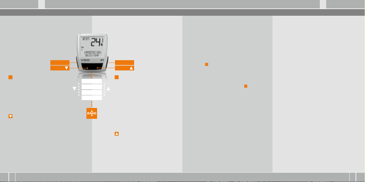
X1 VDO CYCLECOMPUTING60
D GB F I
I F GB D
www.vdocyclecomputing.com X1 61
2. Comando
Per facilitare l’uso del vostro computer abbiamo
creato il sistema EMC = Easy Menu Control.
L’EMC facilita l’uso del computer mediante una
guida menu con testo esteso, simile a quelle
maggiormente in uso nei telefoni cellulari.
C = CLEAR
DOWN
C
= CLEAR
In moda lità funzio ni:
B
Dal sottomenu tornare indietro
di un livello di menu.
In moda lità impos tazione:
B
Ritornare alla modalità funzioni.
B
Correggere un dato impostato.
B
Tornare indietro di una cifra.
= DOWN
In moda lità funzio ni:
B
Scorrere le funzioni verso il basso.
In moda lità impos tazione:
B
Scorrere verso il basso in modalità.
impostazione.
B
Diminuire una cifra.
Gli indicatori menu nel display lampeggianti
segnalano che vi sono altre possibilità di selezione.
In modalità funzioni e in modalità impostazioni
il comando avviene mediante i 4 tasti.
M = MENU
UP
M
FUNCIONE 3
FUNCIONE 4
FUNCIONE 5
FUNCIONE 6
= MENU
In moda lità funzio ni:
B
Richiamare il sottomenu disponibile.
B
Oppure confermare la selezione.
I sottomenu sono riconoscibili per
mezzo degli indicatori di menu
lampeggianti.
In moda lità impos tazione:
B
Selezionare impostazione.
B
Confermare un’impostazione
attuata.
B
Confermare una selezione inserita.
= UP
In moda lità funzio ni:
B
Scorrere le funzioni verso l’alto.
In moda lità impos tazione:
B
Acorrere verso l’alto in modalità
impostazione .
B
Aumentare una cifra..
3. Funzioni di informazioni in modalità funzioni
DIST GIO RN
ndica il percorso del training attuale dall’ultimo
reset. Valore massimo 999,99 km. Quando si supera
il valore massimo il contatore ritorna a zero. Contemporaneamente vengono azzerati i valori di tempo corsa e velocità media.
DIST GIO RN/DI PIU’
DI PIU’ indica che nel menu principale DIST GIORN
vi è un sottomenu. Per aprire i sottomenu premere il tasto M. Il sottomenu comprende:
B
Totale KM BICI 1 fino massimo 99.999 km.
B
Totale KM BICI 2 fino massimo 99.999 km.
B
Somma totale chilometri bici 1 + bici 2
fino massimo 199.999 KM.
Per uscire dal sottomenu premere C.
TEMPO IM PIEG
Indica il tempo corsa del training giornaliero attuale dall’ultimo reset. Massimo 23:59:59 HH:MM:SS
Quando si supera il valore massimo la misurazione
della corsa riparte da zero. Nel contempo si riazzerano il training giornaliero e la velocità media.
VELOC M EDIA
Indica la velocità media, calcolata da training giornaliero e corsa dall’ultimo reset. Precisione: 2 cifre
dopo la virgola. La velocità media viene ricalcolata
quando il training giornaliero o la corsa superano il
valore massimo.
VELOC M AX
Indica la velocità massima nel training attuale
dall’ultimo reset. Precisione: 2 cifre dopo la virgola.
Page 32

X1 VDO CYCLECOMPUTING62
D GB F I
I F GB D
www.vdocyclecomputing.com X1 63
4 Installazione
4.1 Montaggio di sensore, magnete e supporto per manubrio >>> P01
In caso di montaggio con una forcella molleggiata controllare sempre la compressione della
molla della forcella. Il cavo deve avere un gioco
sufficiente.
ATTENZIONE: pericolo di crepe nei cavi
step 1 Inserire la base di gomma sotto il sensore.
Montare il sensore sul lato della forcella sul quale
avete previsto di montare il computer sul manubrio (destra o sinistra), utilizzando la fascetta per
cavi in dotazione (dapprima lenta, non serrare
a fondo).
A seconda dello spazio disponibile il sensore può
essere montato davanti sulla forcella, internamente alla forcella oppure dietro quest’ultima.
>>> P02
step 2 Posizionare il magnete per raggi intorno a
un raggio esterno. L’anima magnetica argentata
è rivolta verso il sensore. Allineare il magnete alla
marcatura del sensore ad una distanza di circa
1 – 5 mm.
step 3 Orientare definitivamente e fissare sensore
e magnete: serrare la fascetta per cavi e premere
con forza il magnete
step 4 Posare il cavo dal sensore già montato lungo il cavo del freno fino al manubrio (fissare con la
fascetta per cavi in dotazione). Ideale: attorcigliare insieme il cavo del sensore e quello del freno.
step 5 Decidere se si vuole eseguire il montaggio a
manubrio o sull’attacco manubrio e di conseguenza ruotare di 90° la base del supporto del manubrio.
A questo punto svitare le viti nel supporto, estrarre la base ed inserirla ruotata di 90°, infine serrare
nuovamente le viti.
ATTENZIONE: non forzare le viti.
step 6 Inserire la fascetta per cavi nella fessura
presente nel supporto del manubrio, guidarla intorno al manubrio o all’attacco manubrio e stringere saldamente (non serrare a fondo).
step 7 Per il montaggio a manubrio: orientare
l’angolo di inclinazione del computer per garantire una perfetta leggibilità. Infine serrare a fondo
la fascetta per cavi.
Tagliare con le pinze le estremità in eccesso.
4.2 Montaggio della batteria nel computer >>> P03
Al momento dell’acquisto il vostro computer
VDO è completo di batteria 3V (mod. 2032).
L’apparecchi viene fornito con la batteria è già
montata. Per cambiare la batteria compiere le
seguenti operazioni:
step 1 Inserire la batteria nell’alloggiamento del
computer con il polo+ verso l’alto.
step 2 Accertarsi che la batteria non sia danneggiata.
step 3 Assicurarsi che la guarnizione in gomma
aderisca perfettamente sul coperchio dello scomparto della batteria.
step 4 Inserire il coperchio dello scomparto della
batteria nell’apertura e girarlo con una monetina
verso destra fino in fondo (ca. 1/3 di giro).
CONSIGLI O per il cambio b atteria : VDO raccoma nda di camb iare la batt eria una volt a all’anno.
Acquist ate per tempo un a batteria nu ova per ass icurare i l perfet to funziona mento.
Quando si esegue il cambio di batteria tutte le impostazione base del computer ritornano ai valori
di default. Per questo motivo prima di togliere la
batteria vecchia è opportuno annotarsi le misure
delle ruote impostate e i chilometri totali finora
percorsi per la vostra bici 1 e bici 2. Questi valori
dovranno essere riprogrammati dopo aver inserito la nuova batteria
4.3 Inserimento del computer nel supporto per manubrio >>> P04
Il sistema twist click VDO garantisce un collegamento sicuro del computer al supporto per
manubrio.
step 1 Inserire il computer nel supporto tenendolo nella posizione delle ore 10.00.
step 2 Ruotare ”twist” il computer verso destra
tenendolo nella posizione delle ore 12.00 e bloccarlo “click” nell’apposito supporto.
step 3 Per estrarre il computer girarlo verso sinistra
(non spingere o estrarre con eccessiva forza).
Aiuti per ricordare:
Dentro (avvitare) verso destra, Svitare verso sinistra
Page 33

X1 VDO CYCLECOMPUTING64
D GB F I
I F GB D
www.vdocyclecomputing.com X1 65
5. Impostazioni di base
5.1 Impostazione lingua
Con i tasti andate su
IMPOSTAZIONI/SELEZIONA.
Confermare con M.
Ora siete in modalità impostazioni (premendo C per 3 secondi
ritornate in modalità funzioni).
per LANGUAGE SELECT.
Confermare con M.
ITALIANO SELEZION OK? Confermare con M.
Feedback del computer: LINGUA SELEZIONE OK.
Il computer ritorna automaticamente nel menu
di partenza IMPOSTAZIONI/SELEZIONA.
per LINGUA ITALIANO.
Confermare con M.
5.2 Impostazione e misurazione della misura della ruota
Per consentire al vostro computer VDO di eseguire una corretta misurazione dovete impostare la
misura della vostra ruota (circonferenza di rotolamento della ruota).
Vi sono 2 alternative:
5.2.1 Scelta da una tabella delle gomme
La tabella delle gomme contiene tutti i modelli
di gomme più comunemente usati. Se il modello
della vostra gomma non è elencato vi consigliamo
di inserire manualmente la misura della ruota.
I valori riportati nella tabella sono indicativi e
possono differire a seconda di marca, altezza e
profilo della gomma. Pertanto tra il percorso misurato e la velocità visualizzata potranno esservi
alcune differenze.
16 x 1,7 5 1272 50,1
20 x 1,7 5 1590 62,6
24 x 1 ⅜ 1948 76,7
24 x 1, 75 1907 75,1
26 x 1 1973 77,7
26 x 1,5 2026 79,8
26 x 1,6 2051 80,7
26 x 1,7 5 2070 81,5
26 x 1,9 2089 82,2
26 x 2,0 0 2114 83,2
26 x 2, 125 2133 84,0
26 x 1 ⅜ 2105 82,9
26 x ¾ 1954 76,9
27 x 1 ¼ 2199 86,6
28 x 1,5 2224 87,6
28 x 1, 75 2268 89,3
28 x 1 ½ 2265 89,2
28 x 1 ⅜ 2205 86,8
30-622 2149 84,6
32-622 2174 85,6
37-62 2 2205 86,8
40-622 2224 87,6
Come imp ostare la m isura delle go mme
selez ionando la go mma:
valore mm valore inch
Con in IMPOSTAZIONI/
SELEZIONA. Confermare con M.
Ora siete in modalità impostazioni (premendo C per 3 secondi
ritornate in modalità funzioni).
Con n DIMENS RUOTA/
IMPOSTAZ Confermare con M.
MISURAZIONE/KMH
Confermare con M o per
cambiare in MPH.
DIMENS RUOTA/BICI 1 (con
per l’impostazione della bici 2)
Confermare con M.
DIMENS RUOTA/TIPO GOMMA:
Confermare con M.
TIPO GOMMA/SELECT
Con selezionate ora
la vostra gomma.
Confermare con M.
Appare la domanda di controllo
“Tipo gomma”/SELEZION OK?
Se la misura della gomma corrisponde a quella
desiderata, confermare con M.
Il display conferma DIMENS RUOTA/IMPOST OK.
Ritorno automatico in IMPOSTAZIONI/SELEZIONA.
Page 34

X1 VDO CYCLECOMPUTING66
D GB F I
I F GB D
www.vdocyclecomputing.com X1 67
5.2.2 Impostazione mediante la circonferenza ruota >>> P05
Per l’inserimento manuale della misura della ruota
dovete in primo luogo misurare la circonferenza di
rotolamento della vostra ruota.
Misura zione dell a circonfer enza
di roto lamento del la ruota:
step 1 Portare la valvola della ruota anteriore
in posizione perfettamente perpendicolare al
pavimento
step 2 Tracciare sul pavimento un segno in
questo punto (ad es. con gessetto).
step 3 Far avanzare la ruota di un giro completo
in avanti, fino a quando la valvola è di nuovo perpendicolare al pavimento.
step 4 Tracciare un segno sul pavimento anche
in questo punto.
step 5 Misurare la distanza tra i due segni tracciati.
Questa misura è la circonferenza della ruota
(circonferenza di rotolamento).
step 6 Inserite nel vostro computer VDO la circonferenza della ruota così misurata.
ATTENZI ONE: se avet e selezion ato il valor e KMH la
circonf erenza de lla ruota de ve essere in serita in mm
(se avete se lezionat o il valore MP H la circonfer enza
della ru ota deve es sere inseri ta in pollic i (inch)).
Proce dura per impo stare la mis ura della ruot a:
Con in IMPOSTAZIONI/
SELEZIONA. Confermare con M.
Ora siete in modalità impostazioni (premendot C per
3 secondi ritornate in modalità
funzioni).
Con n DIMENS RUOTA/
IMPOSTAZ. Confermare con M.
MISURAZIONE/KMH
Confermare con M o
per cambiare in MPH
DIMENS RUOTA/BICI 1
(con per l’impostazione
della bici 2). Confermare con M.
Con n DIMENS RUOTA/
IMPOS MANUAL.
Confermare con M.
BICI 1 ….IMPOST RUOTA/
CONTINUA. Con impostate
ora la circonferenza di rotolamento misurata. Confermare
l’impostazione con M.
Viene visualizzata la domanda: BICI 1/SELEZ OK?
Confermare con M.
Il display conferma. DIMENS RUOTA/IMPOST OK
Ritorno automatico in IMPOSTAZIONI/SELEZIONA
5.3 Impostazione orario
Impos tazione de ll’orario:
Con in IMPOSTAZIONI/
SELEZIONA. Confermare con M.
Ora siete in modalità impostazioni (premendo C per 3 secondi
ritornate in modalità funzioni).
Con in ORA/IMPOSTAZ
Confermare con M.
ORA/OROLOGIO 24H (con
potete passare alla visualizzazione su 12 ore).
Confermare con M.
ATTENZIONE: le impo stazioni d i default sono
2155 mm p er la bici 1 e 200 0 mm per la bici 2.
Se non vie ne impostat a la misura della ru ota,
il compute r lavora con le imp ostazio ni di
default . I valori così m isurati di velo cità, perc orso
ecc. po ssono differ ire sensibilm ente dai valor i
effettivi.
ORA...IMPOST ORA/CONTINUA
Con impostate le ore.
Confermare l’impostazione
delle ore con M.
ORA...IMPOST MIN/CONTINUA
Con impostate i minuti.
Confermare l’impostazione dei
minuti con M.
ORA/SELEZ OK? Confermare con M.
Il display conferma: ORA/IMPOST OK.
Ritorno automatico in IMPOSTAZIONI/SELEZIONA.
Page 35

X1 VDO CYCLECOMPUTING68
D GB F I
I F GB D
www.vdocyclecomputing.com X1 69
5.4 Impostazione totale chilometri
In qualunque momento potete programmare il contatore di percorso (ad es. alla fine di una stagione).
Con in IMPOSTAZIONI/
SELEZIONA. Confermare con M.
Ora siete in modalità impostazioni (premendo C per 3 secondi
ritornate in modalità funzioni).
Con in CONTA KM/
IMPOSTAZ. Confermare con M.
DIST BICI 1/SELEZ OK? Confermare con M.
Il display conferma DIST BICI 1/IMPOST OK.
Ritorno automatico in IMPOSTAZIONI/SELEZIONA.
CONTA KM/DIST BICI 1 (con
ntrate nell’impostazione per la
BICI 2). Confermare con M.
DIST BICI 1…..IMPOST DIST/
CONTINUA. Per impostare la cifra
lampeggiante premere . Per
richiamare la cifra successiva
confermare con M. Ripetere
queste operazioni fino a
quando l’ultima cifra a destra
lampeggia. Confermare con M.
5.5 Commutazione bici 1/bici 2
Il vostro computer VDO può essere utilizzato per
2 bici. Se si passa dalla bici 1 alla bici 2, prima di
partire occorre impostare il computer sulla bici
utilizzata
Con in IMPOSTAZIONI/
SELEZIONA
Confermare con M.
Ora siete in modalità impostazioni (premendo C per 3 secondi
ritornate in modalità funzioni).
Con in BICI/SELEZIONA
Confermare con M.
BICI 1 (con impostate su
BICI 2)Confermare con M.
BICI 1/SELEZION OK?
Confermare con M.
Il display conferma
BICI/SELEZION OK
Ritorno automatico in
IMPOSTAZIONI/SELEZIONA
5.6 Visualizzazione intervallo service
La visualizzazione intervallo service vi ricorda che
dovete far controllare la bici in officina.
L’intervallo service può essere inserito/disinserito
(ON o OFF). Gli intervalli service personalizzati possono essere impostati separatamente per 2 bici.
Quando è stato compiuto il percorso intervallo
service impostato:
B
il simbolo lampeggia nel display.
B
la riga delle informazioni indica MANUT. BICI/BICI 1
Adesso dovete controllare la bici personalmente
oppure farla controllare dal vostro rivenditore.
JPremere un tasto a piacere. Il testo „MANUT.
BICI/BICI 1“ scompare di nuovo. Dopo altri 50 km
scompare di nuovo anche il simbolo .
Potete anche disattivare il simbolo lampeggiante. Per questa operazione inserite di nuovo
l’intervallo assistenza.
La bici selezionata 1) o 2) viene visualizzata in basso
a sinistra nel display. ( )
ATTENZI ONE, nota imp ortante: qu ando si pass a
da bici 1 a 2 o vi ceversa ven gono riaz zerati i dati
del tra ining giornali ero, la cors a, la velocit à
media e la v elocità ma ssima dell’ult imo training.
Come imp ostare gl i interval li servic e
Con in IMPOSTAZIONI/
SELEZIONA. Confermare con M.
Ora siete in modalità impostazioni (premendo C per 3 secondi
ritornate in modalità funzioni).
Con in MANUT. BICI/
IMPOSTAZ. Confermare con M.
MANUT. BICI/ON
(Con inserire OFF)
Confermare con M.
Page 36

X1 VDO CYCLECOMPUTING70
D GB F I
I F GB D
www.vdocyclecomputing.com X1 71
MANUT. BICI/BICI 1
Con passare a BICI 2).
Confermare con M.
BICI 1…IMPOST DIST/CONTINUA
Per impostare la cifra lampeggiante premere . Per richiamare la cifra successiva confermare con M.
Ripetere queste operazioni fino a quando l’ultima
cifra a destra lampeggia. Confermare con M.
BICI 1/SELEZ OK? Confermare con M.
Il display conferma: MANUT. BICI/IMPOST OK.
Ritorno automatico in IMPOSTAZIONI/SELEZIONA.
5.7 Modalità sleep
Il vostro computer VDO è dotato di una funzione
modalità sleep. In modalità sleep il display si
disattiva quasi totalmente per risparmiare la
carica della batteria. Rimangono visualizzati
l’orario e l’intervallo service.
La modalità sleep si inserisce quando per
5 minuti non vengono elaborati impulsi di velocità e non viene premuto alcun tasto.
La modalità sleep termina quando vengono di
nuovo elaborati impulsi di velocità (in marcia)
oppure quando viene digitato un tasto.
5.8 Funzioni reset
Con la funzione RESET si possono riazzerrare a scelta:
B
DATI VIAGGIO
B
TOT DIST 1+2
Nelle varie modalità reset vengono cancellate
le seguenti informazioni:
B
DATI VIAGGIO: training giornaliero, corsa,
velocità media, velocità massima
B
TOT DIST 1+2: totale km, km bici 1, km bici 2
Con
in IMPOSTAZIONI/
SELEZIONA.
Confermare con M. Ora siete
in modalità impostazioni
(premendo C per 3 secondi
ritornate in modalità funzioni).
in CANCEL DATI/
Con
SELEZIONA. Confermare con
Con nei dati che volete
riazzerare:
B
CANCEL DATI/DATI VIAGGIO
OPPURE
B
CANCEL DATI/TOT DIST 1+2
Confermare la scelta con M.
Domanda: SELEZIONE DATI/CANCELLA?
ATTENZI ONE: quest a operazio ne non può
esser e annullata.
Confermare con M, solo se si desidera cancellare
i dati selezionati.
Il display conferma: CANCEL DATI/CANCELLA OK.
Ritorno automatico in IMPOSTAZIONI/SELEZIONA.
M
.
Page 37

X1 VDO CYCLECOMPUTING72
D GB F I
I F GB D
www.vdocyclecomputing.com X1 73
6. Condizioni di garanzia
La VDO Cycle Parts rilascia per il vostro computer
VDO una garanzia di 5 anni dalla data di acquisto.
La garanzia copre i difetti del materiale e di lavorazione del computer, del sensore/trasmettitore
e del supporto per manubrio. Sono esclusi dalla
garanzia i cavi, la batteria e i materiali di montaggio. La garanzia è operante solo per le parti che
non sono state aperte (eccezione: scomparto della
batteria del computer) e che non presentano segni di forzature o danni intenzionali.
Si prega di conservare con cura il documento
d’acquisto, da esibire in caso di reclamo.
Se il vostro reclamo è legittimo vi sarà consegnato
un apparecchio sostitutivo di pari valore. Si esclude il diritto di sostituzione con modello identico
nei casi in cui il modello reclamato non sia più
disponibile a seguito di un cambio di modello.
Per tutti i reclami e i casi di garanzia vi preghiamo di rivolgervi al vostro rivenditore di fiducia
dal quale avete acquistato l’apparecchio. Diversamente potrete spedire il vostro reclamo direttamente a:
Cycle Pa rts GmbH
Große Ahlmühle 33
D-76865 Rohrbach (Germany)
Per eventuali problemi tecnici potete contattarci
al seguente numero hotline:
+49 (0) 6 3 49 - 96 35 - 10.
Maggiori informazioni sono disponibili nel sito:
www.vdocyclecomputing.com
Ci riserviamo eventuali modifiche tecniche finalizzate al perfezionamento del prodotto.
8. Specifiche Tecniche
Comput er:
ca. 45 x 52 x 16 mm, peso ca. 45 g
Suppor to per manu brio:
peso: ca. 15 g
Trasmettitore:
peso ca. 20 g
Batteria computer:
3V, mod. 2032
Durat a batteria co mputer:
1200 ore di corsa, ca. 24.000 km (15.000 M)
Tempera tura d’eser cizio del disp lay:
da -15 °C a +60 °C
Range d i velocità :
con misura della ruota 2155 mm, min 2,5 km/h,
max 199,5 km/h
Camp o di misura temp o corsa:
max. 23:59:59 HH:MM:SS
Camp o di misura cont atore tra ining giorn aliero:
max 999,99 km oppure mi
Camp o di misura tot ale km 1 e 2:
max. 99.999 km oppure mi
Camp o di misura tot ale chilome tri:
max. 199.999 km oppure mi
Camp o di regolazi one circonf erenza ruo ta:
da 100 mm a 3999 mm (da 3,9 a 157,4 inch)
7. Eliminazione dei guasti
Segue un elenco dei probabili errori e delle loro cause, con eventuali rimedi da adottare:
Errore Probabile causa Rimedio
Segmenti dimezzati nella visualizzazione (ad es. dopo un cambio di
batteria)
Velocità non visualizzata Distanza eccessiva tra sensore
Velocità non visualizzata La testa del computer non è
Velocità non visualizzata La circonferenza della bici non
La visualizzazione è debole Batteria scarica Controllare, eventualmente
La visualizzazione è debole Le temperature inferiori a 5°
Dopo il cambio batteria il software del computer non gira
correttamente
e magnete
inserita correttamente nel supporto per manubrio
è impostata correttamente oppure è su zero
ritardano la visualizzazione
Togliete la batteria
ed inserite la nuova
Correggere la posizione del
sensore e del magnete
Inserire la testa del computer
nel supporto da manubrio fino
a battuta (CLICK) e girare
Impostare la circonferenza
della ruota
sostituire la batteria
In normali condizioni di temperatura la visualizzazione si
normalizza.
Page 38

X1 VDO CYCLECOMPUTING74
www.vdocyclecomputing.com X1 75
D
Korrek te Entso rgung dies es Produk ts
(Elektromüll)
(Anzuwenden in den Ländern der Europäischen Union und anderen europäischen Ländern mit einem
sepa raten Sa mmelsys tem). Die Ke nnzeichn ung auf
dem Pro dukt bzw. auf de r dazugehörigen Literatur gibt a n, dass es n ach seiner L ebensdau er nicht
zusam men mit dem nor malen Hau shaltsmü ll entsorgt w erden dar f. Entsor gen Sie diese s Gerät bit te
getren nt von ander en Abfälle n, um der Umwelt b zw.
der mens chlichen G esundheit ni cht durch unko ntrollier te Müllbe seitigung z u schaden . Recyceln S ie
das Ge rät, um die na chhaltige W iederv erwer tung
von stof flichen Re ssourcen z u fördern. P rivate
Nutze r sollten de n Händler, bei d em das Prod ukt
gekauft wurde, oder die zuständigen Behörden
konta ktieren , um in Erfah rung zu bringe n, wie Sie
das Ge rät auf umwelt freundli che Weise rec yceln
können . Gewerbli che Nutze r sollten sic h an Ihren
Liefer anten wend en und die Bed ingungen des Ve rkaufs vertr ags konsul tieren. Di eses Pro dukt darf
nicht zus ammen mit a nderem Gew erbemüll en tsorgt werden.
GB
Correct Disposal of This Product
(Was te Electr ical & Ele ctronic Eq uipment)
(App licable in t he Europea n Union and ot her European co untries wi th separ ate collec tion syst ems).
This ma rking shown o n the produc t or its lite rature,
indica tes that it sh ould not be disp osed wit h other
house hold wast es at the end of i ts workin g life.
To prevent p ossible ha rm to the env ironment or
human he alth from un controlle d waste di sposal,
plea se separ ate this from o ther typ es of waste s
and rec ycle it res ponsibly t o promote the s ustain able re use of mater ial resour ces. Hous ehold user s
should c ontact eit her the ret ailer whe re
they pu rchase d this produc t, or thei r local gov ernment offi ce, for det ails of where a nd how they c an
take t his item for env ironment ally safe r ecycling .
Busine ss users sh ould conta ct their supp lier and
check t he terms an d condition s of the purch ase
contra ct. This p roduct sho uld not be mixe d with
other co mmercial w astes fo r disposal .
F
Comment éliminer ce produit
(déchets d‘équipements électriques
et électroniques)
(App licable d ans les pay s de l‘Union Eu ropéen et
aux aut res pays eu ropéens di sposant de s ystème s
de colle cte séle ctive). C e symbole su r le produit ou
sa docu mentatio n indique qu‘ il ne doit pa s être
éliminé e n fin de vie avec l es autres d échets m énagers. L‘éli mination inc ontrôlée d es déchet s pouva nt
port er préjudic e à l‘enviro nnement ou à la s anté
humain e, veuillez l e séparer d es autres t ypes de dé chet s et le recyc ler de façon r esponsa ble. Vous fa voriser ez ainsi la ré utilisat ion durabl e des resso urces
matér ielles. Le s parti culiers so nt invités à co ntacter
le distr ibuteur le ur ayant vend u le produit ou à s e
rense igner auprè s de leur mair ie pour sav oir où et
comment i ls peuvent s e
débar rasse r de ce produit a fin qu‘il soit r ecyclé en
respe ctant l ‘environn ement. Le s entrepri ses sont
invité es à contac ter leurs f ournisse urs et à consul ter les c onditions d e leur contr at de vente. Ce p roduit ne doi t pas être é liminé avec l es autres d échets
commerciaux.
I
Corretto smaltimento del prodotto
(rifiuti e lettric i ed elett ronici)
(Applicabile in i paesi dell‘Unione Europea e in quelli
con sist ema di racco lta differ enziata ). Marchi o riport ato sul pro dotto o sulla su a document azione
indica c he il prodot to non deve e ssere sma ltito con
altri r ifiuti dome stici al te rmine del cic lo di vita . Per
evit are eventu ali danni all ‘ambient e o alla salut e
causati dall‘inopportuno smaltimento dei rifiuti, si
invit a l‘utente a s eparar e questo pro dotto da alt ri tipi di rifiut i e di ricicla rlo in manie ra respon sabile pe r
favor ire il riutili zzo sost enibile dell e risors e materiali. Gli u tenti dome stici son o invitati a c ontatt are il
riven ditore pre sso il quale è s tato acqui stato il pr odotto o l ‘ufficio l ocale pre posto per t utte le infor mazioni re lative all a raccolt a differen ziata e al ri ciclaggio per qu esto tipo d i prodotto . Gli utenti a ziendal i
sono inv itati a con tattar e il proprio f ornitore e
verificare i termini e le condizioni del contratto di
acquis to. Quest o prodotto n on deve ess ere smalt ito
unita mente ad alt ri rifiuti co mmerciali .
Page 39

www.cyclecomputing.com
SERIES-X
CP-X1-BDA 1 / 1
 Loading...