


VBrick v4.2 Appliance
VB4000-5000-6000 Series
Network Video Appliances
Getting Started Guide
March 18, 2008
4410-0210-0002

Copyright
© 2008 VBrick Systems, Inc. All rights reserved.
12 Beaumont Road
Wallingford, Connecticut 06492, USA
www.VBrick.com
This publication contains confidential, proprietary, and trade secret information. No part of this document may be
copied, photocopied, reproduced, translated, or reduced to any machine-readable or electronic format without
prior written permission from VBrick. Information in this document is subject to change without notice and
VBrick Systems assumes no responsibility or liability for any errors or inaccuracies. VBrick, VBrick Systems, the
VBrick logo, StreamPlayer, and StreamPlayer Plus are trademarks or registered trademarks in the United States and
other countries. Windows Media is a trademarked name of Microsoft Corporation in the United States and other
countries. All other products or services mentioned in this document are identified by the trademarks, service
marks, or product names as designated by the companies who market those products. Inquiries should be made
directly to those companies. This document may also have links to third-party web pages that are beyond the
control of VBrick. Use these links at your own risk. The use of such links does not imply that VBrick endorses or
recommends the content of any third-party web pages. VBrick acknowledges the use of third-party open source
software and licenses
www.vbrick.com/opensource.
in some VBrick products. This freely available source code is posted at http://
About VBrick Systems
Founded in 1997, VBrick Systems, an ISO 9001 certified vendor, is a privately held company that has enjoyed rapid
growth by helping our customers successfully introduce mission critical video applications across their enterprise
networks. Since our founding, VBrick has been setting the standard for quality, performance and innovation in the
delivery of live and stored video over IP networks—LANs, WANs and the Internet. With thousands of video
appliances installed world-wide, VBrick is the recognized leader in reliable, high-performance, easy-to-use
networked video solutions.
VBrick is an active participant in the development of industry standards and continues to play an influential role in
the Internet Streaming Media Alliance (ISMA), the MPEG Industry Forum, and Internet2. In 1998 VBrick
invented and shipped the world's first MPEG Video Network Appliance designed to provide affordable DVDquality video across the network. Since then, VBrick's video solutions have grown to include Video on Demand,
Management, Security and Access Control, Scheduling, and Rich Media Integration. VBrick solutions are
successfully supporting a broad variety of applications including distance learning and training, conferencing and
remote office communications, security, process monitoring, traffic monitoring, business and news feeds to the
desktop, webcasting, corporate communications, collaboration, command and control, and telemedicine. VBrick
serves customers in education, government, healthcare, and financial services markets among others.

VBrick Appliance Getting Started Guide
Organization . . . . . . . . . . . . . . . . . . . . . . . . . . . . . . . . . . . . . . . . . . . . . . . . . . . . . . . . . . . . .vii
Getting Help . . . . . . . . . . . . . . . . . . . . . . . . . . . . . . . . . . . . . . . . . . . . . . . . . . . . . . . . . . . . viii
Font Conventions . . . . . . . . . . . . . . . . . . . . . . . . . . . . . . . . . . . . . . . . . . . . . . . . . . . . . . . . viii
Printer-Friendly . . . . . . . . . . . . . . . . . . . . . . . . . . . . . . . . . . . . . . . . . . . . . . . . . . . . . . . . . . viii
1. Appliance Setup
Setup Overview . . . . . . . . . . . . . . . . . . . . . . . . . . . . . . . . . . . . . . . . . . . . . . . . . . . . . . . . . . . . 1
Using the Quick Start Guide. . . . . . . . . . . . . . . . . . . . . . . . . . . . . . . . . . . . . . . . . . . . . . . 2
Appliance Setup . . . . . . . . . . . . . . . . . . . . . . . . . . . . . . . . . . . . . . . . . . . . . . . . . . . . . . . . . . . . 3
Step 1. Connect Output to a Video Monitor . . . . . . . . . . . . . . . . . . . . . . . . . . . . . . . . . .3
Step 2. Connect an Audio/Video Input Source . . . . . . . . . . . . . . . . . . . . . . . . . . . . . . . . 3
Step 3. Connect to the IP Network. . . . . . . . . . . . . . . . . . . . . . . . . . . . . . . . . . . . . . . . . . 4
Step 4. Power-on the Appliance . . . . . . . . . . . . . . . . . . . . . . . . . . . . . . . . . . . . . . . . . . . . 4
Step 5. Set the IP Address. . . . . . . . . . . . . . . . . . . . . . . . . . . . . . . . . . . . . . . . . . . . . . . . . 4
Step 6. Install StreamPlayer Plus. . . . . . . . . . . . . . . . . . . . . . . . . . . . . . . . . . . . . . . . . . . . 6
Step 7. Verify Operation . . . . . . . . . . . . . . . . . . . . . . . . . . . . . . . . . . . . . . . . . . . . . . . . . . 6
Contents
2. Appliance Upgrade
Overview . . . . . . . . . . . . . . . . . . . . . . . . . . . . . . . . . . . . . . . . . . . . . . . . . . . . . . . . . . . . . . . . . 9
Installing a System Upgrade . . . . . . . . . . . . . . . . . . . . . . . . . . . . . . . . . . . . . . . . . . . . . . . . . . 9
3. Management Tools
Overview . . . . . . . . . . . . . . . . . . . . . . . . . . . . . . . . . . . . . . . . . . . . . . . . . . . . . . . . . . . . . . . . 11
Integrated Web Server. . . . . . . . . . . . . . . . . . . . . . . . . . . . . . . . . . . . . . . . . . . . . . . . . . . 11
Front Panel Edit . . . . . . . . . . . . . . . . . . . . . . . . . . . . . . . . . . . . . . . . . . . . . . . . . . . . . . . 12
VBDirectory . . . . . . . . . . . . . . . . . . . . . . . . . . . . . . . . . . . . . . . . . . . . . . . . . . . . . . . . . . 12
Command Line Interface . . . . . . . . . . . . . . . . . . . . . . . . . . . . . . . . . . . . . . . . . . . . . . . . 13
Telnet. . . . . . . . . . . . . . . . . . . . . . . . . . . . . . . . . . . . . . . . . . . . . . . . . . . . . . . . . . . . . . . .14
Simple Network Management Protocol . . . . . . . . . . . . . . . . . . . . . . . . . . . . . . . . . . . . . 14
VBrick SDK . . . . . . . . . . . . . . . . . . . . . . . . . . . . . . . . . . . . . . . . . . . . . . . . . . . . . . . . . . 15
4. Streaming Video Basics
Video Basics. . . . . . . . . . . . . . . . . . . . . . . . . . . . . . . . . . . . . . . . . . . . . . . . . . . . . . . . . . . . . . 17
MPEG-2 . . . . . . . . . . . . . . . . . . . . . . . . . . . . . . . . . . . . . . . . . . . . . . . . . . . . . . . . . . . . .17
MPEG-4 . . . . . . . . . . . . . . . . . . . . . . . . . . . . . . . . . . . . . . . . . . . . . . . . . . . . . . . . . . . . .20
WM . . . . . . . . . . . . . . . . . . . . . . . . . . . . . . . . . . . . . . . . . . . . . . . . . . . . . . . . . . . . . . . . . 21
Getting the Best Video . . . . . . . . . . . . . . . . . . . . . . . . . . . . . . . . . . . . . . . . . . . . . . . . . . . . .21
Network Considerations . . . . . . . . . . . . . . . . . . . . . . . . . . . . . . . . . . . . . . . . . . . . . . . . . . . . 22
Assigning Multicast Addresses . . . . . . . . . . . . . . . . . . . . . . . . . . . . . . . . . . . . . . . . . . . . 22
IP Address Configuration using Host Names. . . . . . . . . . . . . . . . . . . . . . . . . . . . . . . . . 22
VBrick Appliance Getting Started Guide iii

IP Differentiated Services (Diffserv) . . . . . . . . . . . . . . . . . . . . . . . . . . . . . . . . . . . . . . . 23
VBrick Video Stream Handling. . . . . . . . . . . . . . . . . . . . . . . . . . . . . . . . . . . . . . . . . . . . 24
Network Jitter . . . . . . . . . . . . . . . . . . . . . . . . . . . . . . . . . . . . . . . . . . . . . . . . . . . . . . . . . 24
Typical Applications. . . . . . . . . . . . . . . . . . . . . . . . . . . . . . . . . . . . . . . . . . . . . . . . . . . . . . . . 24
Ethernet IP . . . . . . . . . . . . . . . . . . . . . . . . . . . . . . . . . . . . . . . . . . . . . . . . . . . . . . . . . . .24
One-Way Broadcast and Desktop Streaming . . . . . . . . . . . . . . . . . . . . . . . . . . . . . . . . . 25
Two-Way Interactive Conferencing. . . . . . . . . . . . . . . . . . . . . . . . . . . . . . . . . . . . . . . . . 26
VBrick Accessories . . . . . . . . . . . . . . . . . . . . . . . . . . . . . . . . . . . . . . . . . . . . . . . . . . . . . . . .27
Serial Port Passthrough . . . . . . . . . . . . . . . . . . . . . . . . . . . . . . . . . . . . . . . . . . . . . . . . . . . . .27
How Passthrough Works . . . . . . . . . . . . . . . . . . . . . . . . . . . . . . . . . . . . . . . . . . . . . . . . . 28
Serial Port Passthrough Using Telnet . . . . . . . . . . . . . . . . . . . . . . . . . . . . . . . . . . . . . . . 29
MPEG Features . . . . . . . . . . . . . . . . . . . . . . . . . . . . . . . . . . . . . . . . . . . . . . . . . . . . . . . . . . .30
Billboard . . . . . . . . . . . . . . . . . . . . . . . . . . . . . . . . . . . . . . . . . . . . . . . . . . . . . . . . . . . . . 30
Picture-in-Picture . . . . . . . . . . . . . . . . . . . . . . . . . . . . . . . . . . . . . . . . . . . . . . . . . . . . . . 30
Embedded Web Browser. . . . . . . . . . . . . . . . . . . . . . . . . . . . . . . . . . . . . . . . . . . . . . . . . 30
WM Features . . . . . . . . . . . . . . . . . . . . . . . . . . . . . . . . . . . . . . . . . . . . . . . . . . . . . . . . . . . . . 31
5. Integrated Web Server
Using IWS . . . . . . . . . . . . . . . . . . . . . . . . . . . . . . . . . . . . . . . . . . . . . . . . . . . . . . . . . . . . . . . 33
Login Page. . . . . . . . . . . . . . . . . . . . . . . . . . . . . . . . . . . . . . . . . . . . . . . . . . . . . . . . . . . .34
Welcome Screen . . . . . . . . . . . . . . . . . . . . . . . . . . . . . . . . . . . . . . . . . . . . . . . . . . . . . . . 34
Menu Options . . . . . . . . . . . . . . . . . . . . . . . . . . . . . . . . . . . . . . . . . . . . . . . . . . . . . . . . . 35
Making Changes . . . . . . . . . . . . . . . . . . . . . . . . . . . . . . . . . . . . . . . . . . . . . . . . . . . . . . . 36
Rebooting . . . . . . . . . . . . . . . . . . . . . . . . . . . . . . . . . . . . . . . . . . . . . . . . . . . . . . . . . . . .37
Logout . . . . . . . . . . . . . . . . . . . . . . . . . . . . . . . . . . . . . . . . . . . . . . . . . . . . . . . . . . . . . . . 38
Using Apply, Revert, and Defaults . . . . . . . . . . . . . . . . . . . . . . . . . . . . . . . . . . . . . . . . . 38
Serving Custom ASX and HTML Files . . . . . . . . . . . . . . . . . . . . . . . . . . . . . . . . . . . . . . . . . 39
6. Using the IR Remote
Front Panel Edit. . . . . . . . . . . . . . . . . . . . . . . . . . . . . . . . . . . . . . . . . . . . . . . . . . . . . . . . . . . 41
MPEG-2/MPEG-4 Remote Control . . . . . . . . . . . . . . . . . . . . . . . . . . . . . . . . . . . . . . . . . . . 43
Controlling a VBStar . . . . . . . . . . . . . . . . . . . . . . . . . . . . . . . . . . . . . . . . . . . . . . . . . . . . 44
Controlling VBrick Features . . . . . . . . . . . . . . . . . . . . . . . . . . . . . . . . . . . . . . . . . . . . . . 46
WM Remote Control . . . . . . . . . . . . . . . . . . . . . . . . . . . . . . . . . . . . . . . . . . . . . . . . . . . . . . . 48
7. Command Line Interface
Connection Modes. . . . . . . . . . . . . . . . . . . . . . . . . . . . . . . . . . . . . . . . . . . . . . . . . . . . . . . . .49
Connecting with HyperTerminal. . . . . . . . . . . . . . . . . . . . . . . . . . . . . . . . . . . . . . . . . . . 49
Connecting with Telnet. . . . . . . . . . . . . . . . . . . . . . . . . . . . . . . . . . . . . . . . . . . . . . . . . . 50
MIB-Based Command Line Interface . . . . . . . . . . . . . . . . . . . . . . . . . . . . . . . . . . . . . . . . . . 51
Finding VBrick Parameters . . . . . . . . . . . . . . . . . . . . . . . . . . . . . . . . . . . . . . . . . . . . . . . 52
Setting VBrick Parameters. . . . . . . . . . . . . . . . . . . . . . . . . . . . . . . . . . . . . . . . . . . . . . . . 53
Error Handling . . . . . . . . . . . . . . . . . . . . . . . . . . . . . . . . . . . . . . . . . . . . . . . . . . . . . . . . 56
CLI Examples . . . . . . . . . . . . . . . . . . . . . . . . . . . . . . . . . . . . . . . . . . . . . . . . . . . . . . . . . 57
CLI Sample Script . . . . . . . . . . . . . . . . . . . . . . . . . . . . . . . . . . . . . . . . . . . . . . . . . . . . . . 59
iv Contents

Menu-Based Command Line Interface . . . . . . . . . . . . . . . . . . . . . . . . . . . . . . . . . . . . . . . . . 61
Editing Configuration Parameters. . . . . . . . . . . . . . . . . . . . . . . . . . . . . . . . . . . . . . . . . . 62
Setting and Changing Parameters . . . . . . . . . . . . . . . . . . . . . . . . . . . . . . . . . . . . . . . . . . 62
8. VB6000 Reference
VBrick Appliance Models . . . . . . . . . . . . . . . . . . . . . . . . . . . . . . . . . . . . . . . . . . . . . . . . . . . 65
VB6000 . . . . . . . . . . . . . . . . . . . . . . . . . . . . . . . . . . . . . . . . . . . . . . . . . . . . . . . . . . . . . . 65
VB6000 VBSSM . . . . . . . . . . . . . . . . . . . . . . . . . . . . . . . . . . . . . . . . . . . . . . . . . . . . . . . 65
VB6000 Expanded VBSSM. . . . . . . . . . . . . . . . . . . . . . . . . . . . . . . . . . . . . . . . . . . . . . . 66
Device Interfaces . . . . . . . . . . . . . . . . . . . . . . . . . . . . . . . . . . . . . . . . . . . . . . . . . . . . . . . . . . 67
RS-232/422/485 COM Port Pinouts . . . . . . . . . . . . . . . . . . . . . . . . . . . . . . . . . . . . . . . 67
Ethernet Port . . . . . . . . . . . . . . . . . . . . . . . . . . . . . . . . . . . . . . . . . . . . . . . . . . . . . . . . .68
Power In Entry Interface . . . . . . . . . . . . . . . . . . . . . . . . . . . . . . . . . . . . . . . . . . . . . . . . 68
Power Out Exit Interface . . . . . . . . . . . . . . . . . . . . . . . . . . . . . . . . . . . . . . . . . . . . . . . . 68
Video-In and Video-Out (Composite) . . . . . . . . . . . . . . . . . . . . . . . . . . . . . . . . . . . . . . 68
Video-In and Video-Out (S-Video Interface) . . . . . . . . . . . . . . . . . . . . . . . . . . . . . . . . . 69
AudioMate In . . . . . . . . . . . . . . . . . . . . . . . . . . . . . . . . . . . . . . . . . . . . . . . . . . . . . . . . . 69
Audio In and Audio Out. . . . . . . . . . . . . . . . . . . . . . . . . . . . . . . . . . . . . . . . . . . . . . . . . 69
Relay Port . . . . . . . . . . . . . . . . . . . . . . . . . . . . . . . . . . . . . . . . . . . . . . . . . . . . . . . . . . . .71
Activity LED. . . . . . . . . . . . . . . . . . . . . . . . . . . . . . . . . . . . . . . . . . . . . . . . . . . . . . . . . . 72
Event Triggering . . . . . . . . . . . . . . . . . . . . . . . . . . . . . . . . . . . . . . . . . . . . . . . . . . . . . . . . . .72
Index
VBrick Appliance Getting Started Guide v

vi Contents

VBrick Appliance Getting Started Guide
This document explains how to set up and configure a VBrick network video appliance. It
explains the management tools available and describes some of the fundamental concepts
behind the technology. It also explains how to use the Integrated Web Browser to configure
the appliance and the IR Remote Control to control appliance functions. Your appliance has
two available slots. Depending on what options you purchased, you may have a single
encoder, a dual encoder, or a mixed model (e.g. one encoder and one decoder). You can also
mix and match encoding formats with an MPEG-2 encoder, for example, in Slot1 and a WM
encoder in Slot2. Once your appliance is set up and configured with an IP address, refer to
the following documents as necessary for additional configuration options.
For More Information
VBrick MPEG-2 Appliance Admin Guide
VBrick MPEG-4 Appliance Admin Guide
VBrick WM Appliance Admin Guide
Organization
Appliance Setup Explains the basics. Provides general configuration
recommendations as well as how to cable the appliance and
connect it to the network.
Appliance Upgrade
Management Tools
Streaming Video Basics
Integrated Web Server
Using the IR Remote
Command Line Interface
VB6000 Reference
Explains how to update the appliance's flash memory when
software updates are available. You can us VBDownload or
VBDirectory to perform the update.
Explains how to configure the appliance using a variety of
management tools. These include the IWS web interface,
Telnet, SNMP, the command line, and the IR remote control.
Explains some of the fundamentals behind the technology
including compression techniques, network concepts, serial
port passthrough, and other video basics.
Explains how to use the Integrated Web Server application to
manage VBrick configuration from an external browser.
Explains how to access VBrick appliance functions and control
functions using an optional hand held IR (infrared) remote
control.
Explains how to configure an appliance from the command
line using HyperTerminal or Telnet when an Internet
connection is not available.
Provides back panel drawings, COM port pinouts, LED
descriptions, and other miscellaneous information.
VBrick Appliance Getting Started Guide vii

Getting Help
If you need help, or more information about any topic, use the online help system. The
online help is cross-referenced and searchable and can usually find the information in a few
seconds. Use the tree controls in the left pane to open documents and the up and down
arrows to page through them. Use the
Search box to find specific information. Simply enter
one or more words in the box and press Enter. The search results will return pages that have
all of the words you entered—highlighted in yellow (Internet Explorer only). The
Search box
is not case-sensitive and does not recognize articles (a, an, the), operators (+ and –), or
quotation marks. You can narrow the search by adding words.
If you can't find the information you need from the online help, or from your certified
VBrick reseller, you can contact VBrick Support Services
on the web. Support Services can
usually answer your technical questions in 24 business hours or less. Also note that our
publications team is committed to accurate and reliable documentation and we appreciate
your feedback. If you find errors or omissions in any of our documents, please send e-mail to
documentation@vbrick.com
and let us know. For more information about any VBrick
products, all of our product documentation is available on the web. Go to www.vbrick.com/
documentation to search or download VBrick product documentation.
Font Conventions
Arial bold is used to describe dialog boxes and menu choices, for example: Start > All
Programs > VBrick
Courier fixed-width font is used for code elements (C++, HTML) as well as
filenames, directories, etc.
Black Courier fixed-width font is used to indicate user input in keyboard
commands, scripts, etc.
Folder names and user examples are displayed in this sans serif font.
Folder names and user input are displayed in this bold sans serif font.
Italics are used to emphasize specific words or phrases.
Printer-Friendly
VBrick Appliance Getting Started Guide
T To save or print a PDF document:
1. Click once to open the PDF document in Acrobat Reader.
2. To save or print a PDF document, right-click and select
viii Preface
Save Target As or Print Target.

Appliance Setup
Topics in this chapter
Setup Overview . . . . . . . . . . . . . . . . . . . . . . . . . . . . . . . . . . . . . . . . . . . . . . . . . . . . . . . . . . . . 1
Appliance Setup . . . . . . . . . . . . . . . . . . . . . . . . . . . . . . . . . . . . . . . . . . . . . . . . . . . . . . . . . . . . 3
This chapter explains how to set up and configure all VBrick MPEG and WM network
appliances. The information here is more detailed than the Quick Start Guide that came with
the appliance. You can use this document or the Quick Start Guide to set up and configure
an appliance. Before you do anything else, be sure to unpack and inspect the VBrick
appliance. Each shipment comes with:
• MPEG-2, MPEG-4, or WM network appliance.
•MPEG-2/MPEG-4 and WM Quick Start Guide.
•Power supply.
• Product CD that introduces the appliance and has all documentation.
• Serial port cable and adapter.
• IR Remote Control unit.
• A cable and adapter kit, which includes an Ethernet cable.
Chapter 1
Setup Overview
The VBrick Appliance is shipped with all appropriate cables and a handheld IR remote
control unit. Your appliance has two available slots. Depending on what options you
purchased, you may have a single encoder, a dual encoder, or a mixed model (for example one
encoder and one decoder). You can also mix and match formats with an MPEG-2 encoder,
for example, in Slot1 and a WM encoder in Slot2. The following picture shows an appliance
configured with Slot1 on the upper left side. A second encoder or decoder slot would be
configured in Slot2 on the right. The appliance(s) you actually purchased may vary from this
illustration depending on the type and configuration but the basic elements listed below are
common to all appliances. See VBrick Appliance Models
Figure 1. VBrick Network Appliance – Rear Panel (Left to Right)
Composite In Composite video cable in.
S-Video In S-Video cable in.
on page 65 for more information.
VBrick Appliance Getting Started Guide 1

Mic In AudioMate microphone connection.
Audio In Left/Right Audio in left and right channels.
Power In 24VDC Power input. LED illuminates when power is applied.
COM 1 Dedicated serial port for Serial Port Passthrough.
COM 2 (Term) Use to connect a terminal (or a PC running terminal emulation
software) in order to manage the appliance using HyperTerminal (see
Connecting with HyperTerminal
on page 49). Optional serial port
for Serial Port Passthrough.
Relay Use to control external devices.
Ethernet Connect to the network.
LEDs Activity – indicates there is activity on the network.
Link – indicates the appliance is connected to the network.
10/100 – On indicates the link is running at 100 Mbps. Off indicates
the link is running at 10 Mbps.
Power Out 12VDC Power output. Connect external devices such as a camera.
Figure 2. VBrick Network Appliance – Front Panel (Left to Right)
LCD Display Shows IP Address, system status, error messages, and Edit state. Also
used with
Local Edit on IR remote control.
Infrared Sensor Located between LCD and fan housing. Used for IR remote control.
Figure 3. Appliance Setup Schematic
Using the Quick Start Guide
A Quick Start Guide that explains how to set up the appliance is shipped with each device.
The Quick Start Guides explain how to setup the appliance so you can quickly verify that you
2 © 2008 VBrick Systems, Inc.

Appliance Setup
can stream audio and video from your appliance over your local network. (Your actual
production setup may be different.) Make sure you are using the right MPEG-2/MPEG-4 or
WM Quick Start Guide when setting up the appliance. Use the steps on the following pages
for reference or if you need additional information. The Quick Start Guides are also available
on the Product CD in .pdf format. For best results, print these document in color on 11x17 paper.
Click to enlarge
Figure 4. MPEG-2/MPEG-4 Quick Start Guide
Click to enlarge
Figure 5. WM Quick Start Guide
Appliance Setup
Step 1. Connect Output to a Video Monitor
Optional: MPEG appliances only. Connect a video monitor to the Video Out BNC, S-Video or
SDI connector on the rear of the VBrick (Slot2). Make sure the TV monitor is set to Video
mode. To see if the TV monitor is in the correct mode, you can connect the video source
directly to the TV monitor. Also connect the Left and Right
monitor or to amplified external speakers.
Step 2. Connect an Audio/Video Input Source
An audio/video cable allows the VBrick appliance to receive audio/video from your input
source (a camera, VCR, DVD, etc.).
VBrick Appliance Getting Started Guide 3
Audio Out connectors to the

T To connect input audio/video to the appliance:
1. From a video input source (for example, a camera, DVD, or VCR), connect a BNC
(composite video) cable to
2. Connect
Left and Right cables from the audio source to Audio In on the appliance.
Composite In on Slot1 of the VBrick appliance.
Step 3. Connect to the IP Network
Use an Ethernet cable to connect the appliance to the IP network.
T To connect to the IP network:
1. Plug one end of the Ethernet cable into the Ethernet port on the VBrick appliance.
2. Plug the other end of the Ethernet cable into the network switch.
3. When the appliance is powered on, the green LEDs to the right of the Ethernet port will
illuminate and the
Activity light will flicker.
Step 4. Power-on the Appliance
T To power-up the u n it:
1. Insert the power connector that comes with the unit into the power receptacle on the
rear of the appliance.
2. Connect the other end to a conventional 110/220 VAC power source.
3. The green
will display status messages during self-test and reboot. This can take several minutes.
You should see a solid network Link light and a blinking Activity light.
4. MPEG decoder appliances only. During a portion of the initial power-on sequence, a color
bar test will appear on the monitor.
Power In LED on the back of the VBrick will illuminate and the front panel
Step 5. Set the IP Address
All VBrick appliances are configured by default with DHCP (Dynamic Host Configuration
Protocol) enabled. This means that when you power on the appliance on, if a DHCP server is
present on your network, the VBrick will automatically get its
from the DHCP server. If the VBrick cannot get an IP address from the DHCP server (or a
server is not present), you will need to set the IP address manually using either the handheld
IR Remote Control or HyperTerminal as explained below. Once the IP Address is set, you can
use the Integrated Web Server (IWS) to configure and manage the appliance.
Get the IP Address from a DHCP Server
T To get an IP address from the DHCP server:
1. Connect the appliance to the network and power it on as explained above. All VBrick
appliances are configured by default with DHCP enabled. This means that when you
power on the appliance on, if a DHCP server is present on your network, the VBrick will
automatically get its
happens you are done. Go to Step 6. Install StreamPlayer Plus
2. If the VBrick cannot connect to a DHCP server, it will wait two minutes and then start in
limited run mode using the default IP Address of
automatically reset and again try to obtain a DHCP address. The LCD screen on the
front panel will display a
to cycle through screens, one of which is the configured IP Address.
IP Address and Subnet Mask from the DHCP server. If this
172.17.5.5. After 15 minutes, it will
DHCP failed message and then read VBrick Systems and continue
IP Address and Subnet Mask
on page 6.
4 © 2008 VBrick Systems, Inc.

Appliance Setup
If you want to configure a static IP address, you must do it while the unit is operating in
limited run mode. You cannot access the appliance while it is searching for DHCP server.
You can set a static IP address with the Remote Control or with HyperTerminal as
explained below.
3. If DHCP is successful, the monitor (MPEG appliances only) will display the VBrick logo
in the lower right corner, and audio and video will be present. If the DHCP server
supplies the Gateway IP Address or DNS server address, these parameters will replace
the user-entered Gateway and DNS settings. If the DHCP server does not provide
Gateway information, and if a Gateway is required for your network, you will need to
manually enter a
T To configure a gateway with the remote control:
1. Enter a
2. Enter a
Subnet Mask and press Select.
Gateway IP Address (see note below) and press Select. The appliance will
Gateway IP Address.
reboot with the IP address, subnet mask, and gateway configured.
3. MPEG appliances only. Connect the VBrick to another VBrick over the network using an
Ethernet switch. For unicast, the destination IP Address of the encoding VBrick should
be the IP Address of the decoding VBrick. Make sure the respective destination and
receive ports also match.
Note If the DHCP server supplies the Gateway Address or DNS server address, these
parameters will replace any user-entered Gateway and DNS settings. If the DHCP
server does not provide Gateway information, and if a Gateway is required for your
network, you will need to enter it manually.
Set the IP Address with the Remote Control
As noted, VBrick WM Appliances are shipped with a factory default address of 172.17.5.5.
If necessary, you can change this IP address using the handheld IR Remote control. Remember
that you cannot have multiple VBricks with the same IP address. Use the * button for the decimal
point and the
T To set the IP Address with the IR Remote control:
1. Aim the remote control at the IR port on the front panel and press
display on the front panel of the VBrick will request the password.
2. Press
3. If the network is DHCP-capable and you want the network to select an IP address, press
"Y" and then press
press
4. Enter desired IP address. (Use the * button for the decimal point and the left/right
buttons to erase characters entered by mistake.)
5. When done, press
Select again.
6. If the IP, subnet mask or gateway addresses have been modified and there are no errors,
the VBrick will reboot.
Left and Right buttons to erase.
Local Edit. The
23646 ("admin" numerically) and press Select on the remote control.
Select. The VBrick will reboot and obtain an IP address. Otherwise
Select to continue.
Select. If the remaining settings do not need to be modified press
Set the IP Address with HyperTerminal
T To set the IP Address with HyperTerminal:
1. Connect an ASCII terminal (e.g. HyperTerminal, shipped with Windows 95/98/2000/
NT/XP) from the RJ-45 serial port (
VBrick Appliance Getting Started Guide 5
COM2) on the rear of the VBrick to the COM port

of the computer or terminal device (usually COM1) using the provided cable. See
Connecting with HyperTerminal on page 49 for more information.
2. From the Windows start menu, go to:
Communications > HyperTerminal
Start > Programs > Accessories >
.
3. The port setting is 9600, 8-bit, 1-stop, no parity, flow control = none. The VBrick is a
DTE and the provided serial adapter cable and connector provide connectivity from the
VBrick
COM2 to the PC COM1 or COM2.
4. Press Enter to see Login.
5. The default Login and Password is
admin (case sensitive). Type admin and press Enter
for both Login and Password.
6. Type
be to become the active Editor. Pressing ? displays the VBrick menu. Make
configuration changes as desired.
7. Change the IP Address of the device manually so that it will be recognized on the
network to which it is connected: If the network is not running DHCP,
8. Type
c nt 3 xxx.xxx.xxx.xxx where xxx is the IP Address.
9. Enter a subnet mask:
10. Type
c nt 4 xxx.xxx.xxx.xxx
11. Enter a gateway address if required:
12. Type
c nt 5 xxx.xxx.xxx.xxx
13. Enter Apply to implement these changes and confirm with y. The box reboots with IP
address, subnet mask, and Gateway configured.
14. MPEG appliances only. Connect the VBrick to another VBrick over the network using an
Ethernet switch. For unicast, the destination IP Address of one VBrick should be the IP
Address of the other VBrick. Make sure the respective destination and receive ports also
match.
Step 6. Install StreamPlayer Plus
StreamPlayer Plus is used to view streams and verify operation. WM appliance operation can
be verified using StreamPlayer or Windows Media player. MPEG-2 or MPEG-4 appliances
can be verified only with StreamPlayer.
T To install StreamPlayer:
1. If you did not purchase StreamPlayer go to www.vbrick.com/products/software.asp
web
page to download a 30-day evaluation copy and get a demo license file.
2. If you did purchase StreamPlayer, display the contents of the Product CD with Windows
Explorer.
3. Open the StreamPlayerPlus folder and run the
SetupStreamPlayerPlus.exe program.
4. Browse to the location where you saved your license file or demo file when prompted.
5. Finish the installation.
Step 7. Verify Operation
Use one of the methods below, depending on the type of VBrick you are installing, to verify it
is set up and operating properly.
6 © 2008 VBrick Systems, Inc.

Verify MPEG 2 Operation
T To verify MPEG-2 operation using StreamPlayer:
Appliance Setup
1. Launch the StreamPlayer Plus application from the
All Programs > VBrick > StreamPlayer Plus
All Programs folder. Go to Start >
.
2. The VBrick appliance will broadcast program information to the StreamPlayer Plus
application running on your PC.
3. You should see a stream appear in the
Program Info column of the StreamPlayer Plus
application. The default stream name from the VBrick is the unit's MAC address.
4. Double-click on this stream to launch Windows Media Player and display the selected
video stream on your PC.
5. You are now successfully streaming video to the PC.
Verify MPEG 4 Operation
T To verify MPEG-4 operation using StreamPlayer:
1. Launch the StreamPlayer Plus application from the
All Programs > VBrick > StreamPlayer Plus
2. To request the audio/video stream enter the following command in the
in StreamPlayer.
RTSP://actual IP address of VBrick appliance/VBrickvideo1
The RTSP command consists of the VBrick's network IP address and a user-supplied
program name. The default program name is VBrickvideo1. You should be able to use the
same RTSP command with other media players.
3. Click the Play button (lower left icon) to launch Windows Media Player and display the
video stream on your PC.
4. You are now successfully streaming audio and video to the PC.
All Programs folder. Go to Start >
.
IP Address field
Verify WM Operation
Windows Media Player lets you receive streaming video originating from the VBrick
appliance on a PC. As explained below, you can verify a WM appliance is working properly by
using either HTTP/Unicast or VBrick's StreamPlayer application.
T To verify operation via HTTP/Unicast:
1. Login to the VBrick IWS configuration utility (e.g.
default user name and password (admin/admin).
2. Go to
3. Press the
4. Press
Configuration: Encoder > Server.
Begin Edit button to become the active editor.
Click here to play HTTP to launch a stream in Windows Media Player (assuming
you connected to an Audio/Video Input Source in Step 2 above).
5. If the stream runs in Windows Media Player you are successfully streaming audio and
video to the PC.
Note The default
Cable/DSL-128K, High Motion template for the WM Appliance transmits
at approximately 128 Kbps. If you have a limited bandwidth network connection, or
encounter other network-related problems, trying using a template with a lower rate
bit rate.
http://ipaddressofvbrick) using the
VBrick Appliance Getting Started Guide 7

T To verify operation using StreamPlayer:
1. Launch the StreamPlayer Plus application. Go to
StreamPlayer Plus
.
Start > Programs > VBrick >
2. The VBrick appliance automatically broadcasts program information to the StreamPlayer
application running on your PC.
3. You should see a stream appear in the
Program Info column of the StreamPlayer
application. The default stream name from the VBrick is the unit's MAC address.
4. Double-click on VBrick's MAC address (or host name) to launch the stream in Windows
Media Player and display the selected video stream on your PC.
5. You are now successfully streaming video to your PC.
8 © 2008 VBrick Systems, Inc.

Appliance Upgrade
Topics in this chapter
Overview . . . . . . . . . . . . . . . . . . . . . . . . . . . . . . . . . . . . . . . . . . . . . . . . . . . . . . . . . . . . . . . . . 9
Installing a System Upgrade . . . . . . . . . . . . . . . . . . . . . . . . . . . . . . . . . . . . . . . . . . . . . . . . . . 9
Overview
VBrick appliances are shipped with PC applications to allow for easy upgrade (All release
material should be installed on a PC running Internet Explorer 6.0 and using Service Pack 2
or higher.) Once the release is installed, the upgrade tools become available in the VBrick
program group, located under Start > Programs. The upgrade procedure can be invoked
by using either the VBDownload application or the VBDirectory application. Either
application can be used as the starting point for updating the appliance's flash memory.
(TCP/IP FTP transport services are used for this.) Using VBDirectory is an easier method as
it allows users to choose the appliances by name instead of IP addresses. When VBrick
appliances are not accessible to VBDirectory, the VBDownload application must be used. All
saved configuration parameters are preserved when you upgrade your VBrick. There is no
need to reconfigure the unit after the upgrade other than to take advantage of new features in
the release. The upgrade process does require the unit to be reset, so it is important that your
configuration be saved prior to the upgrade if you want to preserve the settings.
Chapter 2
Part of the process takes place during the first boot after the upgrade of a new release.
During this time you must avoid powering off the unit. This process may take 2-15 minutes
and may include an automatic reboot of the unit. You can tell that the VBrick is ready for
operation when you are able to login via IWS or CLI. VBrick recommends against loading a
previous version of code. Some new features can cause problems for old code versions. For
example, if DHCP is enabled and you load a previous version of code that does not support
DHCP, the VBrick will fail to start and you will need to return the unit to the factory for
repair. Before loading a previous version of code, it is highly recommended that all
parameters be set to defaults.
Installing a System Upgrade
T To upg r ade a V B rick:
1. Double-click on the release executable (
your PC. It is recommended that you accept the default destination folder for the release
which is
2. The setup programs for VBDownload and for VBDirectory will automatically run after
the release files have been extracted. Click
Use the default folders if possible.
3. When the
Program Files\VBrick\VB6000\download\ReleaseVx_x_x.
Maintenance Complete page is displayed, click Finish.
SetupVB6000_x_x_x.exe) to install the release on
Next and follow the on-screen instructions.
VBrick Appliance Getting Started Guide 9

4. Go to Start > All Programs > VBrick > VBDirectory to start the management utility. The
VBDirectory program should launch in a new window showing all VBrick appliances
that are available for upgrade.
5. Select the device to be updated by highlighting the name and then click the
Upgrade
button. (If the user name and password are not set, a dialog box will appear and you will
need to configure the appliances's username and password using the
Password
button.)
Enter Username/
6. In the VBDownload window, if you installed the release to the default directory, that
directory will be auto-selected in the
Revision Folder. If not, Browse to the directory
that contains the unzipped files from the release package.
7. Select a
Revision and press OK to start the download. Since the default mode of
VBDownload is Intelligent Download the utility will query the VBrick to determine
which release components need to be downloaded. When prompted, press OK to allow
VBDownload to upgrade the suggested components. This may take several minutes.
8. When you receive a
Reset Unit radio button and following the prompts (or use the Reset button on the IR
Download Complete window, reboot the appliance by using the
remote).
9. Note that part of the upgrade takes place during the first boot after the download and
may take up to 15 minutes. You can tell the update is complete when you can login via
IWS or CLI or when the device name entry re-appears in VBDirectory.
10. When done close the window or click
Exit.
Note To ve rify t h e down l oad ha s s ucc essfully installed, check the
Status > System Information > Release Revision.
Go to
Release Revision in IWS.
10 © 2008 VBrick Systems, Inc.

Management Tools
Overview
The Integrated Web Server (IWS) configuration tool is an intuitive GUI based management
tool and VBrick recommends using IWS as the primary means of managing VBrick
appliances. You can also use any of the following tools to manage a VBrick:
Tab le 1 . VBrick Management Tools
VBrick Tool Description
IWS The IWS Integrated Web Server allows quick and secure control
through the VBrick's IP interface. See Integrated Web Server
page 33.
Front Panel Edit Front Panel Editing with the use of the IR remote control device. See
Front Panel Edit
VBDirectory VB6000 software ships with VBDirectory, an application that
facilitates finding and accessing all VBricks on a network. A major
feature of this application is that it acts as a user-friendly front-end for
IWS. For more information, see the VBDirectory User Guide.
on page 12.
Chapter 3
on
Command Line CLI Command Line Interface management through the VBrick's
COM2 serial port. See Connecting with HyperTerminal
through Telnet. See Connecting with Telnet on page 50.
SNMP SNMP commands through VBrick's IP interface, including SNMP
Traps.
VBSDK VBrick provides an SDK that lets third-party developers build custom
applications to manage VBricks using HTML or compiled applications.
See the VBrick SDK User Guide for detailed information.
Note There is only one active editing session allowed at any time in a single appliance. In
IWS it is possible to exit a session which still in Edit mode. Other users then must
determine whether or not to log off the previous editor. For that reason, it is
recommended that all editing sessions be ended directly. Telnet, CLI and SNMP
automatically log the Editor off when you exit the program.
on page 49 or
Integrated Web Server
The main card has an embedded Web Server that allows the user to manage VBricks by
configuring appliances from an external browser. This allows network managers to remotely
configure and monitor the appliances from virtually anywhere in the world. Currently, only
Microsoft Internet Explorer is supported and other browsers may not give acceptable results.
Netscape is not actively supported though many of the features may work. VBrick Systems
recommends using Internet Explorer 5.5, Service Pack 2 or better. The user connects to IWS
VBrick Appliance Getting Started Guide 11

by pointing to the IP Address (e.g. http://172.17.5.5) of the VBrick appliance and logging in.
IWS is one of several ways a user can manage the VBrick appliance; however it is the intuitive
and easiest to use. IWS Menus and parameters are described in Integrated Web Server on
page 33.
Front Panel Edit
The Front Panel Edit feature allows you to use the remote control and the front panel display
to change the following parameters: DHCP Enable/Disable, Codec IP, Subnet Mask,
Gateway IP, Receive IP, Receive Port, Destination IP, Destination Port and Show/Hide the
IP Address. This is the easiest way to get a VBrick parameters up and running on a network.
See Front Panel Edit
on page 41 for details.
VBDirectory
VBrick provides a management application called VBDirectory that provides quick reference
and access to all VBrick Appliances on a network. VBDirectory is installed with each new
software release and is also available as a free download from the VBrick
VBDirectory, go to
identify VBricks on the network running code 2.0.0 and higher. It is not backwards
Start > Programs > VBrick > VBDirectory. This directory tool will
website. To access
12 © 2008 VBrick Systems, Inc.

Management Tools
compatible with previous versions of code. For more information about this tool, please refer
to the VBDirectory User Guide.
Command Line Interface
VBrick network appliances can be configured using a standard ASCII terminal or terminal
emulator program connected to the serial port (COM 2) on the rear of the appliance. Simple
commands are used to configure all functions and features. VBrick currently supports two
command line interfaces: a menu-based CLI and a MIB-based CLI (recommended). The
menu-based CLI can only be used to access VBrick parameters for WM v1.1 and VBDNA
v3.3 or earlier. The MIB-based CLI can be used to access all VBrick parameters—past and
present. (Keep in mind that all parameters that are available in the MIB-based CLI are also
available in the web-based IWS application. Always use IWS unless you have a compelling
reason to use the command line.) You can use Telnet, HyperTerminal, or other interfaces to
run the CLI. For more information see Command Line Interface
on page 49.
VBrick Appliance Getting Started Guide 13

Telnet
Ethernet VBricks can be managed remotely via industry-standard Telnet. The same suites of
menus that are displayed on a local terminal are instantly available over an IP network.
VBrick uses the standard Telnet port (23). Telnet uses the same commands as Command Line
Interface (CLI). Both the Telnet and HyperTerminal interfaces are referred to as CLI or
Command Line Interface. For more information see Command Line Interface
on page 49.
Simple Network Management Protocol
The VBrick appliance can also be configured and managed through its MIB, which is
provided on request. Various SNMP management tools are available to issue SNMP based
commands to the appliance. The command structure is similar to CLI and Telnet. It is
necessary to become the active editor and apply the changes before they take effect in the
appliance. Note that the SNMP community strings are the usernames. The following screen
shows a typical, freeware MIB browser.
14 © 2008 VBrick Systems, Inc.

Management Tools
VBrick SDK
The VBrick Software Development Kit enables individuals having a wide variety of abilities
to build applications around VBrick appliances to schedule, record, store, forward, manage,
and control VBrick appliance features. Advanced programming skills are not required in
order to utilize the functionality of the SDK. A basic knowledge of HTML and web
development is enough to create programs that address a specific need. Developers may
easily create applications using popular program languages such as Visual C++, Visual Basic,
VBScript, Javascript, or through the command line interface. The SDK comes with specific
source code examples. VBrick has SDKs for the following devices:
• VB1000-2000-3000 SDK – for MPEG-1 devices.
• VB4000-5000-6000 SDK– for MPEG-2, MPEG-4, and WM devices
• ETV Set Top Box SDK – for VBrick's EtherneTV Set Top Box.
• ETV Portal Server SDK – for VBrick's EtherneTV Portal Server.
VBrick Appliance Getting Started Guide 15

16 © 2008 VBrick Systems, Inc.

Streaming Video Basics
Topics in this chapter
Video Basics. . . . . . . . . . . . . . . . . . . . . . . . . . . . . . . . . . . . . . . . . . . . . . . . . . . . . . . . . . . . . . 17
Getting the Best Video . . . . . . . . . . . . . . . . . . . . . . . . . . . . . . . . . . . . . . . . . . . . . . . . . . . . .21
Network Considerations . . . . . . . . . . . . . . . . . . . . . . . . . . . . . . . . . . . . . . . . . . . . . . . . . . . . 22
Typical Applications. . . . . . . . . . . . . . . . . . . . . . . . . . . . . . . . . . . . . . . . . . . . . . . . . . . . . . . . 24
VBrick Accessories . . . . . . . . . . . . . . . . . . . . . . . . . . . . . . . . . . . . . . . . . . . . . . . . . . . . . . . .27
Serial Port Passthrough . . . . . . . . . . . . . . . . . . . . . . . . . . . . . . . . . . . . . . . . . . . . . . . . . . . . .27
MPEG Features . . . . . . . . . . . . . . . . . . . . . . . . . . . . . . . . . . . . . . . . . . . . . . . . . . . . . . . . . . .30
WM Features . . . . . . . . . . . . . . . . . . . . . . . . . . . . . . . . . . . . . . . . . . . . . . . . . . . . . . . . . . . . . 31
Video Basics
It is important that the source of the video to be encoded and networked be of the highest
possible quality in order to avoid using unnecessary bandwidth to transport source video
artifacts, distortion, etc. If using a camera, exercise common sense; good lighting and a steady
camera will improve overall performance. Cameras, VCR tape players, DVD players, and live
television broadcast feeds from a TV tuner can all be used as video sources. VBrick supports
standard video via BNC connectors, or S-Video via mini-DIN connectors. BNC-to-RCA
adapters are readily available if RCA type cables are used.
Chapter 4
Note Where possible VBrick recommends using S-Video or optional SDI. S-Video output
from the VBrick to S-Video Input on the monitor yields the best video quality and the
Billboard, Program and Conference Guides will be much clearer.
MPEG-2
MPEG-2 (Moving Picture Experts Group) is a standard method of transmitting digital video
and sound in a compressed format that uses less bandwidth than the traditional analog
method. MPEG-2 is the de-facto standard in the digital TV world. MPEG-2 gives high
resolution, scalability and handling of interlaced video for digital video above approximately
2 Mbps. It allows for an excellent picture and allows multiple channels at various bit rates to
be multiplexed into a single data stream. It was officially adopted by ISO and has the catalog
number ISO 13818-1.
MPEG-2 Encoder Compression
Understanding I, B, P Frames, Delay, and Synchronization
In compressed video, each frame is compressed using a "lossy" compression scheme that
takes advantage of the fact that the human eye does not detect certain types of visual
information loss. MPEG compresses files based on I, B, P frames, which contain information
from previous pictures and predictions about future pictures in a Group of Pictures (GOP).
An I-Frame is a full video picture. Because it is likely that a future frame will be similar to a
VBrick Appliance Getting Started Guide 17

past frame (for example, it is likely that the sky will still be on the top of the frame and that it
will still be blue), it is possible to predict portions of a future frame. P-Frames (Predictive)
reference the nearest previous I-frame. Video data that contains only I and P frames requires
less bandwidth than video that contains only I-Frames for comparable quality.
With I-Frames and P-Frames being generated, it is possible to place the P-Frame some
number of frames away from its reference I-Frame, and calculate the contents of the frames
in between using both the I-Frame and the P-Frame as references. These frames are called
B-Frames and are bi-directional (i.e. they are based on a predicted future frame and on a past
frame). Also note that B-Frames are based only on I-Frames and P-Frames, never on past BFrames, so errors are not propagated. VBricks can be configured to produce I-Frames only, I
and P-Frames only, or I, B and P-Frames. In terms of bandwidth usage, I-Frames use the
most, B-Frames require the least. It follows then that I-Frames contain the most information
and B-Frames contain the least information.
Group of Pictures (GOP)
The collection of I, B, and P frames makes up a Group of Pictures (GOP). The selection of
GOP parameters is a trade-off between bandwidth usage, picture quality, sensitivity to
transmission errors, and delay. An extended GOP will be more sensitive to transmission
errors than a small GOP because any error can affect the entire GOP. It is possible to
configure the GOP several ways, for example, I only, IP, IBP, IBBP, etc.
Reference Distance
Reference Distance and Intrapicture Distance are set in
Configuration: Encoder > Video. The
Distance
defines the number of consecutive B pictures
Reference
there are between an I or P picture and then next I or P
picture:
1. No B picture
2. One B picture between I or P pictures
3. Two B pictures between I or P pictures
Intrapicture Distance can be set between 1 and 19 (default is 15) for MPEG-2. The
The
value refers to the number of P or B frames between I frames and defines the Group of
Pictures (GOP).
Interrelationship
Table 2 Reference Distance Settings
illustrates various combinations Reference Distance
settings (up to 3) and GOP Length (up to 19). The GOPs are shown in display order. More P
and B frames increase the compression ratio; however, B frames increase the overall delay. In
general, it is best to chose the highest compression ratio and then try lower ratios (e.g. lower
reference distance) if the video experiences transmission problems.
In operation, a P-Frame will be generated and transmitted before the B-Frame. An MPEG
decoder must, therefore, reorder the incoming frame to display the I-B-P frames in the
correct order. This is done using "presentation time stamps" created by the MPEG encoding
and multiplexing process. This reordering process requires one or more frames be held in the
decoder buffer, waiting it's turn for display, therefore increasing the delay. At 30 frames per
second, each frame requires approximately 33 milliseconds. Synchronized audio is also
compressed using MPEG, and is multiplexed with the video to create an MPEG Transport
Stream.
18 © 2008 VBrick Systems, Inc.

Streaming Video Basics
Note Operation with the DSL4000 requires B frames for correct audio/video
synchronization.
Table 2. Reference Distance Settings
GOP Length (N) Reference Frame Distance
123
1 † †† ††
2 IP †† ††
3IPPIBP††
4 IPPP BIBP IBBP
5 IPPPP IBPBP ††
6 IPP. . . PP BIBPBP BBIBBP
7 IPP. . . PP IBP. . .BP IBBPBBP
8 IPP. . . PP BIBP. . .BP ††
9 IPP. . . PP IBP. . .BP BBI. . .BBP
10 IPP. . . PP BIBP. . .BP IBBP. . .BBP
11 IPP. . . PP IBP. . .BP ††
12 IPP. . . PP BIBP. . .BP BBI. . .BBP
13 IPP. . . PP IBP. . .BP IBBP. . .BBP
14 IPP. . . PP BIBP. . .BP ††
15 IPP. . . PP IBP. . .BP BBI. . .BBP
16 IPP. . . PP BIBP. . .BP IBBP. . .BBP
17 IPP. . . PP IBP. . .BP ††
18 IPP. . . PP BIBP. . .BP BBI. . .BBP
19 IPP. . . PP IBP. . .BP IBBP. . .BBP
†
All I frames.
†† Undefined.
MPEG-2 Delay
This discussion is relevant only for encoder models ending in –xxx1/–xxx2. Low delay mode
is primarily recommended for conferencing applications. Various video artifacts appear when
content with rapid scene changes is encoded at low data rates in low delay mode. The
reference distance is restricted to 1 (no B frames) in low and medium delay modes. If the
Intrapicture distance is set to 1 (all I frames), video disruptions are minimized, but picture
quality is degraded. With other GOP settings, picture quality is improved, but video
disruption may occur on scene changes. At approximately 6 Megabit video rates and above,
video disruption will not occur, depending on content. In low delay mode, delay will be in the
range of 180–190 milliseconds. Video instability is eliminated at medium and high delay
VBrick Appliance Getting Started Guide 19

modes regardless of settings. Delay is approximately 350 milliseconds in medium delay mode
and 450 milliseconds in high delay mode. Delay is set in the Configuration: Encoder >
Transport. The default setting for Delay Mode is set to High.
MPEG-2 Audio
High quality Stereo or Mono audio, fully synchronized with video, may instantly be
transported across the network. VBrick supports 44.1 and 48 kHz sample rates, and data
rates between 192 and 384 Kbps. If the model number ends in -xxx0, the sampling rate can
be 44.1 kHz or 48 kHz. If the model number ends in -xxx1/-xxx2 the sampling frequency is
set at 48 kHz. If the model ends in -xxx0, the transmission rate can be 192, 256 and 384
Kbps. If the model ends in -xxx1/-xxx2 the audio bit rate can be 256 or 384 Kbps. Audio
input and output is standard line-level, as would be found on a conventional VCR. VBrick
offers AudioMate microphone for high quality conference room audio with integral echo
cancellation. For video conferencing applications, appropriate audio conference equipment
such as amplifiers, microphones, and echo control equipment is required.
Table 3. MPEG-2 Optical Loss Budget
MPEG-2 Receiver Sensitivity Transm it Power
MM (maximum reach 3 km) -32 dBm -19 to -14 dBm
SM (intermediate reach 15 km) -28 dBm -15 to - 8 dBm
SM (long reach 1310nM 40 km) -34 dBm -5 dBm
SM (long reach 1550nM 80 km) -34 dBm -5 dBm
MPEG-4
Moving Picture Experts Group MPEG is a standard method of transmitting digital video and
sound in a compressed format that uses less bandwidth than the traditional analog method.
MPEG-4 Part 2 is widely used for distribution of video in the enterprise, on the Internet, and
in mobile applications. VBrick supports a subset of the MPEG-4 Part 2 standard called
Simple Profile. Simple Profile offers optimal interoperability with MPEG-4 from multiple
vendors. MPEG-4 provides moderate resolution and offers scalability for digital video up to
approximately 2 Mbps.
MPEG-4 Encoder Compression
MPEG-4 Part 2 Simple Profile video compression uses many of the same basic compression
features as MPEG-2 discussed above. There are several significant differences worth
mentioning. This protocol does not support B frames. Although B frames offer some
compression benefits, more modern compression schemes such as MPEG-4 gain only
marginal benefits from B frames. In addition B frames always add additional latency since
reordering is required on transmission. This protocol does not have a fixed GOP structure. I
frames are inserted either at a configured rate or when the protocol itself determines that the
scene has changed sufficiently such that it is more efficient to insert an I frame.
MPEG-4 Audio
VBrick's MPEG-4 appliances offer AAC-LC compressed audio. This compression algorithm
is the industry-standard method for audio to accompany MPEG-4 video streams. VBrick
supports Stereo, Mono, and Dual audio for MPEG-4. Sample rates between 8 kHz and 48
20 © 2008 VBrick Systems, Inc.

kHz and data rates between 8000 and 320000 bits/sec are supported to allow transmission
over a wide variety of media ranging from low-speed Internet delivery to high-speed LANs.
WM
Microsoft Windows Media is a ubiquitous technology that makes it easier for VBrick
customers to deploy video for one-way video delivery to millions of PCs and multimediaequipped devices worldwide. "Windows Media" describes Microsoft's multimedia product
technologies for Windows. It includes (1) Windows Media Format tools for encoding and
decoding audio and video, (2) Window Media Services for publishing streaming audio and
video on a server, and (3) Windows Media Player, which is the client program that plays
Windows Media and other multimedia formats. The Windows Media Player is typically
installed with the operating system on most desktop PCs so no player-side installation is
necessary, eliminating a common IT concern when deploying a streaming audio/video
solution. VBrick licensed Windows Media encoding and server technology from Microsoft
and created the VBrick WM Appliance to interoperate with other Windows Media
compatible products including all versions of Windows Media Player and all versions of
Windows Media Server.
Getting the Best Video
Streaming Video Basics
Video quality is a subjective concept that depends on a variety of factors. VBrick's
philosophy is to make our network appliances as flexible as possible so they can be used
effectively in different applications on a wide variety of networks. This means you can
configure an appliance for maximum performance but you can also configure it in such a way
that it will only work well in a very limited environment. Video quality is also relative. What is
acceptable quality for a surveillance application on a low-bandwidth network is most likely
unacceptable for a corporate presentation or a two-way video conference on a high-speed
LAN. Much depends on your network, the bandwidth you have available, and the audience
you are trying to reach.
VBrick tries to anticipate as many obstacles and limitations as possible and provides customdesigned MPEG-4 and WM (Windows Media) templates for a variety of applications. These
templates are designed to provide the highest quality audio and video—using bit rate, frame
rate and resolution settings that are tailored for a variety of common network environments.
We encourage you to override specific template settings in order to meet the unique
requirements of your own site, but in doing so, be aware that you can also degrade the quality
and/or performance of the audio and video you are trying to deliver.
For best results, start with a pre-built template and then adjust the bit rate, frame rate,
resolution, and other parameters with care. Experiment with different settings to see the
trade-offs in quality and performance. You can track your changes by periodically saving the
configuration file using the
Configuration page in IWS. If the audio and video quality is still less than you would expect,
re-apply one of the standard templates and try again. Keep in mind that the VBrick is stable,
reliable and flexible. In most cases a small amount of experimentation will help you find the
configuration settings that will deliver the best audio and video your network can support.
For more information, or help configuring your appliance, contact VBrick Support Services
Read/Write option on the Maintenance: Read/Write
.
VBrick Appliance Getting Started Guide 21

Table 4. Video Resolution
Video Resolution NTSC PAL
Full D1 720 x 480 720 x 576
2/3 D1 480 x 480 480 x 576
1/2 D1 352 x 480 352 x 576
SIF 352 x 240 352 x 288
Network Considerations
A number of features that address video stream handling across networks are described
below. These include:
Assigning Multicast Addresses
IP Address Configuration using Host Names
IP Differentiated Services (Diffserv)
VBrick Video Stream Handling
Network Jitter
Assigning Multicast Addresses
Many factors must be considered when designing a multicast address infrastructure since
Ethernet switch implementations can significantly vary between vendors. Furthermore,
multicast addressing techniques rely on an Ethernet to IP Address mapping rule, which does
not guarantee a unique physical address. In fact, it is possible to create multicast addresses
that differ from an IP perspective, but overlap when presented to the Ethernet network.
Addresses created in this situation can cause significant network and operational problems.
Specifically, multiple IP Addresses are mapped into the same physical layer address. For
example, all IP multicast addresses with the same or differing first octet, and the second octet
differing by exactly 128, map to the same physical address (226.5.5.4, 227.5.5.4, and
228.133.5.4 all map to the same physical address).
Another factor to keep in mind when assigning multicast addresses is that 224.x.x.x is a range
containing reserved addresses, particularly in the range 224.0.0.x. For example, 224.0.0.1 is
the 'all hosts' multicast address and 224.0.0.2 is the 'all routers' reserved address. Other
224.0.0.X numbers are reserved for RIP, OSPF, DVMRP, etc. Here are some recommended
rules for multicast IP Address assignment:
1. Do not use 224 in the first octet since many of these are reserved.
2. Use a digit between (225–239) for the first octet and standardize on it for each network.
3. In the second octet, either use numbers from 1–127, or
given network.
129–255, do not mix ranges on a
IP Address Configuration using Host Names
This feature provides VBricks the ability to unicast to one another, recognizing each other by
Host Name instead of IP address. This is especially useful when appliances are running
DHCP, since IP addresses can change between being rebooted, whereas Host Names remain
the same unless manually changed by the user. Each IP address that can be configured using
22 © 2008 VBrick Systems, Inc.

Streaming Video Basics
Host Names has an Address Mode parameter. This configuration parameter allows the user
to specify how the address is to be configured: IP Address or Host Name. If Address Mode
is set to "Host Name," the IP address field becomes a status field and is used to report the IP
Address of the configured Host Name. Likewise, if
Address Mode is set for "IP Address,"
the Host Name field is used to report the Host Name of the configured IP Address. If the
configured IP address is multicast, the Host Name field will be blank. The following rules
apply:
• The following addresses can be configured using Host Names:
Encoder network destination address
Pump network destination address
Decoder network receive address
Recorder network receive address
Passthrough dedicated address
• Multicast addresses cannot be configured using Host Names.
•The
Management SAP Transmit parameter of the referenced VBrick has to be set to
Enabled for this feature to work.
• The Host Name feature does not work if the appliance is in edit mode. Please exit Edit
mode when finished configuring the appliance.
IP Differentiated Services (Diffserv)
Type of Service settings control the level of priority a service or source receives while
traveling through a network. VBrick supports setting the IP TOS (Type of Service) in
accordance with RFC-791, RFC-1112 and RFC-2474 (Differentiated Services Field in the
IPv4 Header). You can set the Type of Service field in the IP header to any value, decimal 0
to 255.
Table 5. TOS Settings
Priority Level Type of Service
111 Network Control
110 Internetwork Control
101 CRITIC/ECP
100 Flash override
011 Flash
010 Immediate
001 Priority
000 Routine
Bit 3 0 = Normal delay
1 = Low delay
Bit 4 0 = Normal throughput
1 = High throughput
Bit 5 0 = Normal reliability
1 = High reliability
VBrick Appliance Getting Started Guide 23

Bits 6–7 Reserved for future use.
Example
To set the Type of Service to all 0's enter 0. To set the Type of Service to all 1's, enter 255. IP
Differentiated Services redefine how the historical TOS field is used. Diffserv allows IP
networks to provide certain Quality of Service features. Note: If uncertain as to whether the
network supports TOS or Diffserv, VBrick recommends setting the TOS to the default value
of 0.
VBrick Video Stream Handling
Packet Ordering is the process of accommodating video packets that are arranged "out of
sequence" when they arrive. This feature optimizes the quality of video in networks that are
less stringently engineered. The condition of packets arriving "out of sequence" can occur for
several reasons. These might include networks having redundant or overlapping routes,
routing table instability problems, local area networks that are not properly switched, or
excessive wide area networking (WAN) delays. Through buffering, the VB6000 rearranges the
delivery of packets to the decoder, so they are received as an ordered set. Enabling the Packet
Ordering feature adds up to 85 milliseconds of additional delay between the encoded stream
and the decoded stream. Packet Ordering can be enabled or disabled in Configuration:
Decoder > Network section of IWS.
Network Jitter
The Jitter Queue compensates for IP network jitter conditions by imposing a slight delay
between the arrival of video packets at the VB6000 and rendering of packets to the decoder.
The process of jitter compensation involves the creation of a buffer that temporarily stores
all packets before they are presented to the decoder. The Jitter Queue uses elastic storage
capability within the buffer, which allows for up to 85 milliseconds of delay variation between
video packets. Enabling the Jitter Queue feature adds 85 milliseconds of additional delay
between the encoded stream and the decoded stream. The Jitter Queue is enabled or disabled
in Configuration: Decoder > Network section of IWS.
Typical Applications
Ethernet IP
Ethernet VBricks operate over standard 100Base-T Ethernet. It is important that the
network is engineered to accommodate the constant payload such that data is delivered
between VBricks without delay, and that the load does not degrade network performance. In
general, operating over Ethernet Switches that are not oversubscribed provides adequate
bandwidth and QoS. For streaming video (e.g. one-way "broadcast") applications, latency in
the network is much less of an issue than for two-way full duplex conference applications.
24 © 2008 VBrick Systems, Inc.

Streaming Video Basics
VBricks send and receive MPEG video via UDP/IP at 1 to 15 Mbps (plus audio and
overhead). Assuming each VBrick is on a separate 100Base-T segment, less than 10% of the
segment's capacity can be used. Video can be transmitted point-to-point between VBricks for
two-way conferencing or video can, using IP multicast, be broadcast to an unlimited number
of TV's connected to VBricks; and to an unlimited number of PC's that are using the VBrick
StreamPlayer or StreamPlayer Plus software. Note: the network must be IP Multicast capable
for multicast streaming applications.
One-Way Broadcast and Desktop Streaming
VBrick 4xxx and 62xx models provide a powerful streaming broadcast and desktop streaming
solution. Each VBrick is capable of multicasting live video IP streams to an unlimited
number of desktop clients in a given network. "Live" VBricks in the network automatically
announce a user-definable program name of the video source to all of the VBricks and
StreamPlayer or StreamPlayer Plus™ applications that are operational across the network. A
VBrick announcement is known as a SAP, or Session Announcement Protocol, as defined by
the IETF standard committee and set forth in RFC 2974. The StreamPlayer or StreamPlayer
Plus applications allow users to view content using an ordinary PC. Each StreamPlayer or
StreamPlayer Plus application identifies the program name by the transmitted SAP, which
displays all currently available VBrick video. With StreamPlayer, the user selects a stream for
viewing by selecting the transmitted SAP from the VBrick, which identifies the video in the
program guide. On a television monitor, a user can select the appropriate VBrick SAP
program name through the use of the provided remote control device.
This illustration shows a VBrick in a network multicasting live video traffic to other VBrick
appliances as well as to the desktop clients using StreamPlayer or StreamPlayer Plus. The
program stream is displayed on the desktop client and the user can view the stream in real
time. This application can be expanded to include previously recorded material such as
VBrick Appliance Getting Started Guide 25

training tapes and pre-recorded VHS tapes. Since the Session Advertisement Protocol, or
SAP, containing the name of each program are small and are only sent periodically, they have
practically little or no impact on the network bandwidth.
Two-Way Interactive Conferencing
For two-way interactive conferencing applications, appropriate audio conference equipment
such as amplifiers, microphones, and echo control equipment is required. Contact VBrick for
accessories. VBrick 6200's enable automatic two-way television via IP unicast. Each VBrick in
the network automatically announces its "name" to other VBricks in the network and displays
a conference guide on a TV screen. The conference guide indicates who is available for a
conference. It is only necessary to select from the list of names to establish a two-way video
communications.
These illustrations show how the conference system works. In the example, two VBricks are
connected to an IP network, with each VBrick assigned a Calling Name. Each VBrick sends
its name, along with IP Address information, onto the network. Each VBrick also receives a
list of available names from the network. Using the IR Remote Control, each VBrick can see
a list of the available names, plus whether they are free or busy. To place a call, select the
party and when the call is answered, a two-way, private, unicast video conference is
established.
26 © 2008 VBrick Systems, Inc.

Because the name advertisements are small and only sent periodically, they have practically no
impact on the network. These advertisements are typically sent to a default multicast address,
but may be configured to be broadcast or configured to be sent to any valid IP Address.
Once the call is established, the calling party may "ring" the other end to get their attention,
if desired.
• Several configuration options are available:
• Enable/Disable Conference.
• Enable/Disable Ringer.
• Auto answer – the party receiving the call does not have to answer. The VBrick
automatically receives the call and two-way video is instantly available.
• Manual Answer – the party receiving the call must answer it before the call is established.
• How often to advertise the Call Name.
• The address on which to advertise the Call Name.
• Two-way interactive conferencing may be initiated from the IR remote handheld device.
VBrick Accessories
VBrick units have a number of optional hardware accessories, including the AudioMate
microphone, remote control devices and cameras. These work directly with VBrick
appliances or through the use of ActiveX control software, also available from VBrick. For
information about microphones, cameras and other VBrick hardware accessories, please
contact VBrick directly. ActiveX controls for cameras and other software accessories are also
available from VBrick.
Streaming Video Basics
Serial Port Passthrough
When configured properly, VBricks provide full duplex, end-to-end transparent passthrough
of user data from one VBrick to another, or to other IP devices. Two serial ports are
provided, each independently supporting this feature. COM1 is dedicated to Passthrough.
COM2 is normally used for management control, but may be configured to support
Passthrough, depending on the VBrick hardware revision. Each serial port operates at its
configured baud rate (e.g. 110 to 115.2K bps). See the MPEG-2 or MPEG-4 Admin Guide
for configuration details. Some common applications include:
• Remote control of a camera, pan-tilt-zoom.
• Remote control of a security door lock.
• Low speed data transport.
• Data collaboration between PCs.
Note Passthrough mode is used to send control information from one VBrick to another
and may not support sustained data at higher data rates.
VBrick Appliance Getting Started Guide 27

How Passthrough Works
VBrick appliances are able to receive data on a particular TCP/IP port and transparently
output that data to a serial port. Conversely, any data input to a serial port can be passed
through to other devices connected to that TCP/IP port. Devices include other VBricks or
special applications connected to the appropriate TCP/IP port. This feature is called "Serial
Port Passthrough." COM1 is assigned port 4439 while COM2 uses port 4414. A typical
application is for two VBricks connected to each other's TCP/IP port 4439. In this case,
characters typed into a terminal program attached to one VBrick's serial port appear on a
terminal program attached to the other VBrick's serial port. In this case, the TCP/IP network
serves as an intermediary between the serial ports of two VBrick appliances.
You must select configuration settings to enable Serial Port Passthrough. First it is necessary
to decide if the appliance will be designated as an
connections. If configured as an Initiator it will continuously attempt to setup a Passthrough
connection to other devices. When configured as a Responder it will accept up to 64
connections from
Initiator appliances. It is possible to Disable Passthrough Mode, so that the
VBrick neither initiates nor responds to Passthrough requests. If a VBrick is set to be an
Initiator, a Destination must be selected. The appliance will use the destination information
when trying to establish a connection. The destination can be configured as follows:
•Dedicated
•Remote COM1/COM2 using Slot1 Video endpoint
•Remote COM1/COM2 using Slot2 Video endpoint
• Slot1/Slot2 MetaData
Initiator or Responder of Passthrough
Dedicated means that the initiator will attempt to make a Passthrough
connection to the Dedicated Address and Port configured by the
user. Please note that the Dedicated Address Port configuration
parameters are used only when the initiator destination is set to
Dedicated. The Dedicated Address can either be configured using
IP Address or Host Name. The Dedicated Address Mode
parameter is used to specify whether the IP Address or Host Name
will be used. If the Dedicated Address Mode is set to Host Name,
the Dedicated Address is configured using the Dedicated Host
Name parameter. Likewise, if the Dedicated Address Mode is set
to IP Address, the Dedicated Address is configured using the
Dedicated IP Address parameter.
Slot1 Video Endpoint
Slot2 Video Endpoint
use address information that is configured for the device in that
slot. If the device in that slot is an encoder, the initiator will
attempt to establish a Passthrough connection to the unicast
Destination IP Address configured as Destination 1 for that slot.
Note: Passthrough is supported using Destination 1 only;
Destination 2 has no meaning for the Passthrough operation. If
the device is a decoder, the initiator will attempt to establish a
Passthrough connection with the address configured as the
Decoder Receive IP Address and Port. The receive address can be
either multicast or unicast.
28 © 2008 VBrick Systems, Inc.

Streaming Video Basics
Remote COM1
Remote COM2
are as implied. This selection determines which serial port will be
accessed on the Responder appliance. In "Slot1 or Slot2 Video
Endpoint" cases, the Passthrough port for the Remote/Responder
appliance's COM1 port is 4439. Access to the remote appliance's
COM2 uses port 4414.
Slot1 MetaData
Slor2 MetaData
specifies the slot into which you will insert incoming serial data as
metadata.
Since the medium used for setting up Passthrough connections is a generic TCP/IP port, any
IP device that is prepared to connect to a VBrick's port can be considered as a Passthrough
Initiator. The VBrick Responder appliance will not know the exact nature of the device at the
other end of the port. For example, a generic Telnet client configured to connect to a VBrick
on port 4439 will cause a VBrick
Responder to start sending data from it's serial port, using
the connection it accepted from the Telnet client.
If the appliance is configured as an
Initiator and the Responder appliance has Passthrough
disabled or is not on the network it will continue to try to establish a connection.A VBrick
appliance must be configured as a Responder to accept Passthrough connections initiated by
other devices. In addition to the Initiator versus Responder selection, the serial port
operation settings must be entered to establish a connection, baud rate, stop bits etc.
Note Once a Passthrough connection is established between VBricks the actual flow of data
is symmetric between the ends of the connection. That is, the behavior of the serial
ports with respect to typed characters will appear to be the same at both ends, Initiator
and Responder.
Serial Port Passthrough Using Telnet
As mentioned in the previous section, either serial port can be accessed over Ethernet via a
Telnet client. A VBrick appliance configured as a Passthrough Responder will accept a
connection request to TCP ports 4439 (COM1) and 4414 (COM2). The request can come
from a Telnet client or other PC application. Any data sent by the PC to TCP ports 4439 and
4414 will be delivered out of the VBrick serial ports and any data present on the VBrick serial
port will be sent to the connected PC.
If multiple Telnet sessions are active on one VBrick (each VBrick supports up to 64 sessions),
the data from the VBrick will be sent to all connected PC's, and the data received by the
VBrick from the PC's will be delivered on the serial port. If multiple Telnet sessions are
active and each is sending data to the VBrick, the data delivered by the RS-232 port will be a
mix of characters presented in the order they were received (e.g. the data from all the senders
is bridged together). This feature provides a method to broadcast alarm status or other
information to multiple locations.
VBrick Appliance Getting Started Guide 29

MPEG Features
Billboard
The Billboard feature allows you to display text and/or graphics on a TV monitor. The
displayed billboard can span multiple pages with each page displayed for a specified period of
time. Some uses of the billboard feature are to announce a daily calendar of events, directions
to a particular conference room or even a slide presentation in conjunction with displayed
video. VBrick models 62xx, 52xx and 53xx have a built in mini-browsers that support viewing
limited HTML pages. The pages can either be kept inside the VBrick as part of the file
system, or can be located on a remote HTTP server. Each page of the billboard is laid out as
an HTML page with text and graphics created using the HTML tags supported. If billboard is
to be supported on a remote server, the appliance requires read access to the HTTP server
and may need to be configured. See the MPEG-2 or MPEG-4 Admin Guide for
configuration details.
Picture-in-Picture
(PIP) VBrick Decoder Picture-in-picture (PIP) is a video display mode in which a small video
image is superimposed on a quadrant or smaller area of a video screen. This small image or
window can be opened in order to display a second video input source on a monitor. The
MPEG-2 decoder provides picture-in-picture capability, which allows the input from the
local encoder to be displayed on the local decoder's output. This is a useful capability when
using the appliances in video-conferencing mode by allowing the near-end user to view him/
herself in a small window while simultaneously viewing the far end. Note that PIP can only be
used to display local encoder input and is available for encoder/decoder models only. PIP does not
operate when closed captioning is enabled.
Note If closed captioning is enabled while PIP is enabled, closed captioning will not be
displayed on the monitor until PIP is disabled.
Embedded Web Browser
VBrick appliances have an embedded Web Browser that allows users to display HTML pages
on the decoder's output (i.e: a monitor). This is a powerful tool that can be used for data
collaboration across a network during video conferences. The web browser is a great tool for
allowing data collaboration between remote sites. Benefits and features include:
• It allows for exchange of .jpg, and .gif images and .html pages.
• Images or pages can reside inside the box (in flash memory) or on an external web
server.
• It can be turned On or Off through
control.
• It operates with VBrick's SCAT program, allowing instant capture of Windows desktops
and transferring that image to a VBrick (or to any Web server).
Example 1
An HTML page and graphic image resides in flash. This is by default and when shipped from
the factory an HTML page example is loaded into flash memory. It will display several .JPG
images automatically when the billboard is turned On. There are 4 HTML pages with each
having a JPG image inside of it. HTML page 1 points to page 2, page 2 points to page 3, etc.
Billboard key in both the IWS and on the remote
30 © 2008 VBrick Systems, Inc.

Streaming Video Basics
This is how the "page flipping" effect is created. The URL to enter that will make this happen
is:
–File://./BB01/VB_1.HTM
Example 2
An HTML page or image can reside on a PC. Your PC must be set up as a Web Server. This
is actually easier than you think since Microsoft provides a PWS (Personal Web Server)
application that takes five minutes to install. Once installed you can place either an HTML
page or image (JPG, BMP, GIF, etc) into the web server directory (wwwroot) on the PC and
point the MPEG-2 browser to it. An example of a URL is that makes this happen is:
–http://172.16.3.148/image.jpg (example, use your own IP Address)
Example 3
An HTML page can reside on the WWW. You must enter a Gateway IP Address, primary
server IP Address and default domain extension in the Configuration: Network page on the
IWS. Note that many WWW HTML pages use java that the VBrick browser does not
understand. In this case the billboard will display an error message and may (or may not)
display some of the HTML page. Examples of URL's that make this happen are:
http://www.VBrick.com or http://www.yahoo.com
http://www.VBrick.com or /billboard/navigation.htm
WM Features
The VBrick WM Appliance converts analog video and audio from any source into digital
Windows Media streams. It attaches to your network and delivers the streaming video and
audio directly to any Windows Media-compatible player or server. The VBrick can deliver the
streams via multicast to any number of players on the network and it can serve the stream via
unicast to up to 200 players or servers. The VB6000 WM Appliance has the following
standard features:
• Accepts composite or S-Video input.
• Available as single or dual channel.
• Multiple bit rate support.
• Windows Media Video 9 encoding (bit rates 20 Kbps–4 Mbps).
• Windows Media Audio 8 encoding (bit rates 5 Kbps–192 Kbps).
• Optional 60 GB hard drive for local archiving.
• HTTP Push from a WM appliance reflector source to any of the following destinations:
•Multicast.
• Served HTTP and RTSP unicast (Pull)
•Archive to a File.
• HTTP Push.
• Multicast Streaming (UDP).
• Any combination of up to 200 clients including:
• Unicast RTSP Streaming (UDP).
• Unicast HTTP Streaming (TCP).
• Stream Push (25 maximum) to Microsoft Windows Media Server or RealNetworks
Helix Server via HTTP (TCP).
• Stream Pull from Windows Media Server or RealNetworks Helix Server via HTTP.
VBrick Appliance Getting Started Guide 31

32 © 2008 VBrick Systems, Inc.

Integrated Web Server
Topics in this chapter
Using IWS . . . . . . . . . . . . . . . . . . . . . . . . . . . . . . . . . . . . . . . . . . . . . . . . . . . . . . . . . . . . . . . 33
Serving Custom ASX and HTML Files . . . . . . . . . . . . . . . . . . . . . . . . . . . . . . . . . . . . . . . . . 39
Using IWS
The VBrick WM Appliance has an Integrated Web Server (referred to throughout this
document as IWS) that lets you manage VBrick configuration from an external browser. This
allows network managers to remotely configure and monitor the appliances from virtually
anywhere. Currently, only Microsoft Internet Explorer is supported. Other browsers (for
example Netscape) may not give acceptable results. VBrick recommends using Internet
Explorer 6.0 or higher. You connect to IWS by pointing to the IP Address (for example:
http://192.168.5.5.) of the VBrick appliance and logging in. (Note that passwords passed
between client and server are encrypted.) IWS is one of several ways you can manage the
VBrick encoder (you can also use VBDirectory or the Command Line Interface
but it is the most intuitive and easiest to use.
Chapter 5
Interface)
To login to a VB6000 Series VBrick with Microsoft Internet Explorer, you must have
Session Cookies and Active Scripting enabled. Depending on your browser version, these
settings are in the
correct username and password will refresh the screen without login. If Active Scripting
cannot be enabled, check with your system administrator to see if it was disabled at the server
level. To avoid having the IWS window closed when accessing a different VBrick, go to Tools
> Internet Options > Advanced and uncheck the
Security or Privacy tabs in Internet Options. If either option is disabled, a
Reuse windows for launching shortcuts.
VBrick Appliance Getting Started Guide 33

Login Page
Figure 4. Login Page
T To login t o IWS:
1. Enter the IP address of the VBrick in the address bar.
2. Login to IWS with a valid user name and password (case-sensitive), and then click the
Log In button. The default user name and password is admin and admin. Use the
Maintenance pages in IWS to change the user name and password. The user name and
password cannot exceed 20 characters. It may include any combination of alphanumeric
characters and only the following special characters:
~ ! # $ ^ * + & % [ ] { } | < >
Table 6. Levels of Authority
User Level Default User Name Default Password Privileges
Administrator admin admin Read, diagnostics, edit, change
passwords.
Operator operator operator Read, diagnostics, edit.
Diagnostics diagnostics diagnostics Read, diagnostics.
Public public public Read.
Welcome Screen
A successful Login displays the Welcome screen shown below which indicates the login name
and the appliance IP address.
34 © 2008 VBrick Systems, Inc.

Figure 5. Welc ome Pag e
Integrated Web Server
Network appliances may be configured with a single encoder or with dual encoders.
Consequently the screens you see in IWS will vary depending on whether the encoder has
one or two slots. The images in this document show an encoder configured with one slot.
Menu Options
The basic menu options are shown below. The top menu bar is available at all times. The left
column contains configuration options. Configuration Options affect selection of individual
pages. Different configurations appear depending on how the appliance is configured. Selections are
hardware dependent. For instance, dual decoders do not have an encoder selection. SDI and
MPEG-4 equipped units have some differences for encoders, decoders, or both. Network
Appliances may be configured with a single encoder or with dual encoders. Consequently the
screens you see in IWS will vary depending on whether the encoder has one or two slots. A
appliance includes Configuration options unique to the hard drive, including Pump, Recorder
and FTP options. It also contains different Status pages and Diagnostic settings.
Option Description
Configuration Used to configure all appliance settings.
Status Used to monitor status of main board and the encoder.
Diagnostic Used to troubleshoot appliances.
Maintenance Used for providing overall appliance information, managing usernames
and passwords, and reading or writing configuration files from or to
the VBrick appliance.
Help Provides on-line help. Internet access is necessary to use this function.
Home Hot button to return to Home page.
Logout Logs you out of the system.
VBrick Appliance Getting Started Guide 35

Making Changes
In order to change configuration settings in the VBrick encoder, you must log in so that
multiple users cannot change parameters simultaneously. By clicking on the button labeled
Begin Edit, you become the editor and the message Edit Session In Progress is displayed on
the front panel of the appliance. Only one user may be in Edit mode at any time. Any user may
end the editing session of any other user using IWS or CLI, regardless of login level—admin
or operator. As a best practice, you should click Begin Edit, make changes and then Save
and End Edit so as not to interfere with other users.
Config
Note All configuration screens have a View mode and an Edit Mode. All screens in this
document are shown in
Edit Mode, that is after you click Begin Ed it.
Figure 6. View Mode
36 © 2008 VBrick Systems, Inc.

Integrated Web Server
Figure 7. Edit Mode
End Edit Ends the editing session and displays View mode.
Save Config Writes all applied changes to flash
memory. If you do not click Save
Config after editing, any changes you
made are lost if the appliance loses
power or is reset.
If the browser is closed after entering the Edit Mode, Editing will not be ended. Therefore, a
second user can't know if the first user has simply forgotten to log off or is still engaged in
editing. After an hour of inactivity, Edit Mode times out, whether the browser is open on the
desktop or closed without ending the Edit session. In IWS, the Logout button on the right
side of the menu bar ends editing and logs you out of the application.
Rebooting
T To to reset the VBrick appliance do one of the following:
1. Power the VBrick appliance up and down by removing and reinserting the power cord.
2. Press the
Diagnostic. This button is only available while in the Edit mode.
Reset Box button on the Integrated Web Server in any of the selections under
VBrick Appliance Getting Started Guide 37

3. Use the Reset button on the optional IR remote control device if the IR feature has been
enabled in the Configuration: System section of IWS.
Logout
Pressing Logout on the navigation bar exits from IWS and ends any editing sessions. If you
have purchased a VBStar appliance, the link to view the hard drive content from the
Integrated Web Server launches an additional Internet Explorer window. After logging out of
the IWS, it is a good idea to close all Internet Explorer windows and exit Internet Explorer.
Using Apply, Revert, and Defaults
Depending on screen resolution, the Apply, Revert and Defaults buttons may not be visible
on the screen. It may be necessary to scroll down to view the selection buttons or to view
second slot features.
Apply Applies the changes made on the screen to the appliance. Note that
these changes will not be stored in the appliance's flash memory until
you click
the changes will be lost. Don't forget to save the configuration.
Revert Aborts all changes made on the screen and returns to the values that
were present prior to the first change that was made. Note that this
only applies to changes made prior to the last "apply."
Save Config. This means if the appliance is powered down
Defaults Returns to the default settings for the parameters on that page. Using
Apply is necessary for those settings to take effect.
38 © 2008 VBrick Systems, Inc.

Multiple Applies
In Edit mode, on some screens it is possible to have more than one Apply button. It is
necessary to make sure the correct Apply is used for the section of the screen in which the
change is made. Using Apply on one section of the screen may change which settings are
available in other sections of that screen. Also, be sure to scroll down to the bottom of the
screen, to make sure all selections are visible. When there are dual encoders, each slot is configured
independently of the other.
Serving Custom ASX and HTML Files
VBrick WM appliances create and serve built-in .asx files that are used to launch streams.
VBrick appliances can also serve custom .html or .asx files that you create and store in Flash
memory on the VBrick's C: drive. For example, you may want to use the VBrick as a web
server to launch custom .html or .asx files. Custom .asx files are typically used for playlists;
custom .html files are useful for web pages that have an embedded media player. To support
this functionality, the appliance recognizes the following special file names. These special files
can be stored in Flash memory at
customized and served as necessary.
ftp://admin@<VBrick_IP_Address>/WEB/ and can be
Integrated Web Server
Custom1.asx
Custom2.asx
Custom3.asx
Custom4.asx
Custom5.asx
For example, you can create and save a file called
Custom1.html
Custom2.html
Custom3.html
Custom4.html
Custom5.html
Custom1.html that is recognized as a special
file name and will be available from the VBrick web server. The file Custom6.html is not
recognized and will not be served. Note that .asx files are text files that manage the streaming
of .asf files. They are very small (less than 1K) because they contain instructions and no data.
When a you click a link to an .asx file, the browser downloads it to the browser cache,
launches the Windows Media Player, and then starts streaming the file. When the Player
interprets the .asx file, it accesses the streaming media specified in the .asx file. The following
snippet shows typical content inside an .asx file:
<ASX VERSION="3">
<ENTRY>
<REF HREF="http://<Server_IP_Address>/videofile.wmv"/>
<REF HREF="http://<VBrick_IP_Address>:8080/vbrickvideo1"/>
</ENTRY>
</ASX>
VBrick Appliance Getting Started Guide 39

40 © 2008 VBrick Systems, Inc.

Using the IR Remote
VBrick appliances support features provided through an optional hand held IR (infrared)
remote control. The IR remote enables users to access VBrick appliance functions and
control functions with simple program commands. Front Panel Edit options are model
dependent. For example, a dual encoder will allow editing of two destination IP Addresses
and ports. The IR remote control has limited functionality. If enabled, you can use the IR
remote control to set the IP address and perform certain other functions. Use the * button
for the decimal point and the Left and Right buttons to erase entries. Aim the remote at the
sensor on the front panel IR Port of the encoder. To enable or disable the IR remote, go to
Configuration: System > General > IR Enable. The remote is enabled by default.
Topics in this chapter
Front Panel Edit. . . . . . . . . . . . . . . . . . . . . . . . . . . . . . . . . . . . . . . . . . . . . . . . . . . . . . . . . . . 41
MPEG-2/MPEG-4 Remote Control . . . . . . . . . . . . . . . . . . . . . . . . . . . . . . . . . . . . . . . . . . . 43
WM Remote Control . . . . . . . . . . . . . . . . . . . . . . . . . . . . . . . . . . . . . . . . . . . . . . . . . . . . . . . 48
Chapter 6
Front Panel Edit
The Front Panel is the LCD display on the front of the unit. Certain keys (see below) on the
IR remote control can be used to set configuration parameters. Front Panel Edit can be
invoked by pressing
(which is admin, numerically). Press the Select key to enter. IR remote control of Local Edit
is set in IWS under Configuration: System > General > IR Enable. Entering the operator
password (default =
Gateway IP. Entering the administrator password (default = admin) allows changing all of the
configurable parameters.
Table 7. Front Panel Edit Keys
Key Description
Up Terminate string from cursor
# Terminate string from cursor.
* Period (.) used in IP addresses.
Down Backspace.
Left Shift cursor to the left.
Right Shift cursor to the right.
Select Change current setting and continue to next setting.
Local Edit key on the remote control. The default password is 23646
operator) will not allow changing the IP Address, Subnet Mask, or
Next Page Don't change current setting and continue to next setting.
Numbers Numbers for editing.
VBrick Appliance Getting Started Guide 41

Key Description
Letters Letters for password and for responses. "6" corresponds to "n" for a
no response, "9" corresponds to "y" for a yes response.
Table 8. Front Panel Error Messages
Error Message Description
Edit in Progress Edit session in progress; Sign off any SNMP/CLI/IWS edit sessions.
Syntax Err 1 Syntax error.
Syntax Err 2 Syntax error.
Out of Range Value out of range.
Invalid Gateway Invalid Gateway Address or conflict with Gateway Address.
Invalid IP16 Attempt to enter IP with host ID equal to 0.
Invalid IP17 Attempt to enter broadcast address as IP.
Used Port Port in use.
Assigned Port Port has been assigned.
Invalid Mask23 Subnet mask makes IP Address a broadcast address.
Invalid Mask24 Subnet mask makes Gateway Address a broadcast address.
Invalid Mask25 Subnet mask makes Gateway Address invalid.
Other Errors Retry later. If error persists, contact VBrick Support Services.
Table 9. Front Panel Dialog Windows
Dialog Window Description
Password At this screen use the letter keys to enter in the current password
followed by the select key. Entering the operator password will not
allow you to change the IP Address, Subnet Mask, or Gateway IP.
Entering the case sensitive administrator password (admin) allows you
to change all of the configurable parameters.
DHCP Enable/Disable. If you enable DHCP (Dynamic Host Configuration
Protocol) the VBrick will reboot and attempt to obtain a dynamic IP
Address (6 = no, disable; 9 = yes, enable).
Box IP Addr This screen will display the current IP Address of the VBrick. If the
current setting does not need to be modified press the select key.
Otherwise enter in the correct value followed by the select key.
Subnet Mask This screen will display the current Subnet Mask of the VBrick. If the
current setting does not need to be modified press the select key.
Otherwise enter in the correct value followed by the select key.
42 © 2008 VBrick Systems, Inc.

Using the IR Remote
Dialog Window Description
Gateway This screen will display the current Gateway of the VBrick. If the
current setting does not need to be modified press the select key.
Otherwise enter in the correct value followed by the select key. If the
Box IP, Subnet Mask or Gateway IP has been modified and there are
no errors reported on the front panel, the VBrick will now reboot.
Slot x Dest IP This screen will display the current Destination IP Address for Slot x
of the VBrick. If the current setting does not need to be modified press
the select key. Otherwise enter in the correct value followed by the
select key.
Slot x Dest Port This screen will display the current Destination Port for Slot x of the
VBrick. If the current setting does not need to be modified press the
select key. Otherwise enter in the correct value followed by the select
key. If the Destination IP or Destination Port has been modified and
there are no errors reported on the front panel, the VBrick is now
using the new settings.
Slot x Rcv IP Addr
Screen
MPEG appliances only. This screen will display the current Receive IP
Address for slot x of the VBrick. If the current setting does not need
to be modified press the select key. Otherwise enter in the correct
value followed by the select key.
Slot x Rcv Port
Screen
MPEG appliances only. This screen will display the current Receive Port
for slot x of the VBrick. If the current setting does not need to be
modified press the select key. Otherwise enter in the correct value
followed by the select key. If the Receive IP or Receive Port has been
modified and there are no errors reported on the front panel, the
VBrick is now using the new settings.
Show BoxIP This will allow the enabling or disabling of the scrolling IP Address on
the Front Panel Display of the VBrick appliance for security (6 = no, 9
= yes).
MPEG-2/MPEG-4 Remote Control
VBrick appliances support features provided through an optional hand held IR (infrared)
remote control. The IR remote enables users to access VBrick appliance functions and
control functions with simple program commands. Front Panel Edit options are model
dependent. For example, a dual encoder will allow editing of two destination IP Addresses
and ports. The IR remote control has limited functionality. If enabled, you can use the IR
remote control to set the IP address and perform certain other functions. Use the
for the decimal point and the
sensor on the front panel IR Port of the encoder. To enable or disable the IR remote, go to
Configuration: System > General > IR Enable. The remote is enabled by default.
Left and Right buttons to erase entries. Aim the remote at the
* button
VBrick Appliance Getting Started Guide 43

• Reset – Press twice within five seconds to reset the VBrick. The
appliance will reboot.
• Encoder Off/On – Turns the encoder off for privacy.
• Slot1, Slot2 – Selects which slot is to be controlled via the
remote. This is relevant for dual encoder and dual decoder
models only.
• PIP – Turns PIP Off/On. This is relevant for encoder/decoder
models only.
• Local Edit – Used for Front Panel Edit.
• Camera – Used for Camera control, when applicable. Not
supported in current release.
• Hard Drive – Displays the "Play" guide.
• Billboard – Displays the Billboard.
• Con Guide – Displays the Conference Guide.
• Pro Guide – Displays the Program Guide.
• Up – Function Dependent.
• Down – Function Dependent.
• Left – Function Dependent.
• Right – Function Dependent.
• Select – Function Dependent.
• Zoom In / Prev Page – Function Dependent.
• Zoom Out / Next Page – Function Dependent.
• <<, n , > ||,>> – Rewind, fast Forward, etc.
• Record – Starts recording to the hard drive. Screen indication is
a red record icon.
• Send – Initiates an FTP transfer to a pre-configured
destination.
• Conference
• Previous – Toggle to previous call.
• Ans Call – Answer a call.
• Rej Call – Reject a call.
• Ring RMT – Ring the remote.
• Ring DIS – Disable local ringer.
• Ring ENB – Enable local ringer.
• Hang Up – Disconnect a conference.
• Aux 1 – 4 Unused.
Controlling a VBStar
A VBStar is an MPEG-2 appliance which can record incoming streams for store and forward
use on an included 60 GB hard drive. The following functions are available using the
handheld IR Remote Control when you have an MPEG-2 VBStar with a decoder:
44 © 2008 VBrick Systems, Inc.

Using the IR Remote
Tab le 1 0. Using the IR Remote with a VBStar Decoder
Button Description
Record Press the Record button to start recording the stream that is currently
playing on the TV. Press the Record button again to stop recording.
Send Press the Send button to start an FTP transfer of the last recorded
file.
Hard Drive Press the Hard Drive button to access the Play Guide. The Play
Guide shows a list of files available on the VBStar for playback. When
the Play Guide is displayed the following buttons are available:
• Select – Start local TV playback of the highlighted file or move to
the highlighted directory.
• Up – Scroll up through the selections.
• Down – Scroll down through the selections.
• Prev Page – Scroll up one page.
• Next Page – Scroll down one page.
• Hard Drive – Press the Hard Drive button to hide the Play Guide.
Pro Guide + Record Press the Pro Guide Button to access the Program Guide. When the
Program Guide is displayed press the Record button to access the
Record Guide. The Record Guide lists all programs emitting program
guide advertisements that are available on the network. When the
Record Guide is displayed the following buttons are available:
• Select – Start a dedicated record of the highlighted program. (The
program playing on the TV is not affected.)
• Up – Scroll up through the selections.
• Down – Scroll down through the selections.
• Prev Page – Scroll up one page.
• Next Page – Scroll down one page.
• Record – Press the Record button to hide the Record Guide.
Hard Drive + Send Press the Hard Drive button to access the Play Guide. When the Play
Guide is displayed press the Send button to access the FTP Guide.
The FTP Guide shows a list of files available on the VBStar for FTP.
When the FTP Guide is displayed the following buttons are available:
• Select – Start an FTP transfer of the highlighted file or move to
the highlighted directory or choose FTP servers.
• Up – Scroll up through the selections.
• Down – Scroll down through the selections.
• Prev Page – Scroll up one page.
• Next Page – Scroll down one page.
• Send – Press the Send button to hide the FTP Guide.
The following IR functions are available on an MPEG-2 VBStar model without a decoder:
VBrick Appliance Getting Started Guide 45

Tab le 1 1. Using the IR Remote without a VBStar Decoder
Button Description
Record Press the Record button to start recording. The recorder must have
been preconfigured with an address and port. Press the Record button
again to stop recording.
Send Press the Send button to start an FTP transfer of the last recorded file.
Controlling VBrick Features
When the VBrick is operational, you can use the IR Remote to control certain VBrick
features such as VBStar Record, Picture in Picture, the Billboard, the Conference Guide, and
the Program Guide. There are five icons displayed on the screen with Billboard, Conference
Guide, and Program Guide.
Tab le 1 2. VBrick Feature Icons
Icon Description
Handcuffs – Indicates there is a user in Edit mode.
Smiley face – Waiting for display.
Traffic Light – Too much activity. Pause and try again
Red Circle – Record.
Yellow Square – Stop.
Picture In Picture
PIP can be turned on and off on the Configuration: Decoder > Picture in Picture page in
IWS.
PIP – Displays Picture-in-picture. Toggles between display off and on.
When the PIP is on the screen and neither the Program Guide,
Conference Guide, or Front Panel Edit Functions are in use, the
following function dependent keys are enabled on the IR remote
control:
• Up – PIP to upper left corner
• Down – PIP to lower right corner
• Left – PIP to lower left corner
• Right – PIP to upper right corner
• Select – PIP to center Conferencing
Billboard
Billboard can be enabled or disabled through IWS (Configuration: Billboard). For
information on how to create and use Billboard pages, see the MPEG-2 or MPEG-4 Admin
Guide.
46 © 2008 VBrick Systems, Inc.

Using the IR Remote
Billboard – Display listing of .htm "billboard" pages available in the
VBrick appliance. Files must be FTPed to the correct folder in order to
be seen. Pressing Billboard again toggles to start/stop display.
Conference Guide
The IR remote control of Conferencing can be enabled or disabled on the Configuration:
Conferencing > Conferencing Setup page in IWS.
Conference – Lists the VBricks set up to receive video conferencing.
Pressing Conference Guide again toggles to start/stop display. There
are two modes for Conference Guide. The first brings up a list of users
on the monitor. The following actions are possible in that mode:
• Up – Scroll up through the selections.
• Down – Scroll down through the selections.
•Prev Page – Page up.
• Next Page – Page down.
• Select – Attempt to connect to the highlighted user.
Once a connection is made, the second mode makes the following
selections possible:
• Previous – Toggle to previous call.
• Ans Call – Answer a call.
• Reject Call – Reject a call.
• Ring Rmt – Ring the remote.
• Ring-DIS – Disable local ringer.
• Ring-ENB – Enable local ringer.
• Hang Up – Disconnects a conference.
VBrick Appliance Getting Started Guide 47

Program Guide
Pro Guide – Lists all programs emitting Program Guide
advertisements and currently available on the network. Pressing Pro
Guide again toggles to start/stop display.
Pro Guide + Select – Chooses the program to play. Pressing Pro Guide
again toggles to start and stop the display.
• Selecting Pro Guide allows you to make the following selections.
Once you have made a selection, depressing the Program Guide
button removes the menu from the screen.
• Up/Down – Scroll up or down through the selections.
• Select – Plays the selected program.
• Left – Plays the previous program selection in the Program Guide
list.
• Right – Plays the next program selection in the Program Guide.
•Prev Page – Page up.
• Next Page – Page down.
• Record – Selects Record Guide.
WM Remote Control
The IR remote shown below works with multiple VBrick products. The following text does
not describe all of the functions and controls. It describes only those controls which are functional
with the VB6000 WM Appliance.
• Reset – Press twice within five seconds to reset the VBrick. The
appliance will reboot.
• Encoder Off/On – Turns the encoder off for privacy. Turns
off multicast and push; does not affect HTTP or RTSP server
functions.
• Local Edit – Enter or exit Front Panel Edit.
• Record – Starts/stops hard drive archiving. You cannot use this
command when IWS is in Edit mode.
• Send – Initiate an FTP transfer of the last archived file. You
cannot use this command when IWS is in Edit mode.
• Up – Function dependent.
• Down – Function dependent.
• Left – Function dependent.
• Right – Function dependent.
• Select – Function dependent.
• Prev Page – Function dependent.
• Next Page – Function dependent.
48 © 2008 VBrick Systems, Inc.

Command Line Interface
Topics in this chapter
Connection Modes. . . . . . . . . . . . . . . . . . . . . . . . . . . . . . . . . . . . . . . . . . . . . . . . . . . . . . . . .49
MIB-Based Command Line Interface . . . . . . . . . . . . . . . . . . . . . . . . . . . . . . . . . . . . . . . . . . 51
Menu-Based Command Line Interface . . . . . . . . . . . . . . . . . . . . . . . . . . . . . . . . . . . . . . . . . 61
Connection Modes
Telnet (as well as FTP, IWS, and SNMP) can be disabled for security purposes. If you cannot
login to the appliance, check that Telnet is enabled. Go to Configuration: System > Security
> External Telnet Server.
Connecting with HyperTerminal
VBrick's command line interface is simple, intuitive, and menu driven. To manage an
appliance with HyperTerminal, connect the included cable (which provides a standard 9-pin
serial connection) from the serial port on the computer to the VBrick's COM2 RJ-45
connector. To access the VBrick using HyperTerminal go to
Accessories > Communication > HyperTerminal
Communications Port (usually COM1).
. Connect through your computer’s
Start > Programs >
Chapter 7
Upon connection to a terminal (9600 bps Async, 8-bit, no parity, flow control = none), a
prompt for login (username) and password will be displayed. (Ethernet VBricks also support
Telnet. The display is identical to that of a local terminal.) Login and password are case
sensitive (admin). Once logged in, the main menu will appear by typing a question mark (?) at
the VBrick> prompt.
VBrick Appliance Getting Started Guide 49

Connecting with Telnet
Ethernet VBricks can be managed remotely via industry-standard Telnet. The same suites of
menus that are displayed on a local terminal are instantly available over an IP network.
VBrick uses the standard Telnet port.
T To login using Telnet.
1. Go to
2. Type
Start > Run and type telnet to open a Telnet window.
? and press Return to display the menu options.
3. Type
open <ip_address> using the IP address of the Vbrick Appliance.
4. Enter the Login name and Password. Default is admin and admin.
5. At the VBrick prompt, type ? to display the top-level commands.
50 © 2008 VBrick Systems, Inc.

Command Line Interface
Note There are some Global Commands that can be used with both CLI and Telnet. Global
Commands are accepted at any menu level. For example, to browse to a menu
selection and make a change, you can type
be or beginedit command instead of
navigating back to the editing menu. Note that the reset control is in the Diagnostic
D/RB).
menu (
MIB-Based Command Line Interface
All VBrick appliance parameters are accessible via an industry-standard SNMP Management
Information Base (MIB). This section explains how to access VBrick appliance parameters
using the COM2 serial port or over an IP network. You can use HyperTerminal or ProComm
with the serial port for example, or Telnet or PuTTY over an IP network. The VBrick 40005000-6000 Series was originally designed with a menu-based Command Line Interface that
was used for control. This functionality is still in place for backward compatibility but has
been superseded by the MIB-based CLI, a syntactically simpler interface which is more
suitable for computer-to-computer interfaces. The syntax for each VBrick parameter is
documented in the SNMP MIB for the appliance. The MIB-based CLI is also suitable for
users who cannot use the alternative SDK or SNMP interfaces because of their development
environments or tools. All subsequent CLI references in this document refer to the MIBbased CLI.
You can use a variety of tools to create scripts that use the CLI. Some common examples are
ProComm, HyperTerminal, Telnet, and PuTTY. In short, to send input commands to a
VBrick appliance, you can use ProComm, Telnet, scripts, cut-and-paste, or any program that
supplies text-based input via the get and set commands described here. The command set for
the CLI includes
multiple bit rate are not available on the menu-based CLI and can only be accessed via the
MIB-based CLI.
The menu-based Command Line Interface (CLI) can be used to access VBrick
Note
parameters for WM v1.1 and VBDNA v3.3 or earlier. VBrick parameters added to
subsequent releases may not be available in the menu-based CLI. You must use the
MIB-based CLI to access these new features.
SVAR, GVAR, STAB, GTAB. Note that newer appliance features such as
VBrick Appliance Getting Started Guide 51

T Use these steps to find and set VBrick appliance parameters with the CLI:
1. Find the parameter you want to set or change. You can do this with a variety of methods.
See Finding VBrick Parameters
on page 52.
2. Set the parameter using valid values obtained from the MIB. See Setting VBrick
Parameters on page 53.
3. Apply the changed value(s) using the
ApplySet command for that group as specified in
the MIB. See Applying Changes on page 56.
4. Optional. Save the configuration file. See Saving Changes
on page 56.
All CLI commands are shown in the following table. You will need to login to the VBrick and
begin an edit session before you can make any changes. Once the parameters have been set to
the correct values, you must do an
ApplySet. If the response to any ApplySet does not match
the value of the set, an error message is displayed. Use care when typing commands. All
commands and parameter names used with the CLI are case sensitive.
Tab le 1 3. CLI Command Syntax
Command Response
SVAR vbrickMIBNAME=value
GVAR vbrickMIBNAME
STAB vbrickMIBNAME.row=value
GTAB vbrickMIBNAME.row
The serial port is also used by the VBrick appliance to emit system messages. In order
Note
$!MIBNAME=value
$!MIBNAME=value
$!MIBNAME.row=value
$!MIBNAME.row=value
or $!ERROR=errorstring
or $!ERROR=errorstring
or $!ERROR=errorstring
or $!ERROR=errorstring
to allow the script writer to distinguish between direct responses to commands and
other output, all CLI response messages have
$! as leading characters. Any responses
that do not begin with these characters can be safely ignored.
It is important to note that some commands also cause a reboot of the VBrick. In order to
notify the command initiator when this happens, the string
$!Rebooting … is emitted from
the VBrick. In this case the commanding entity must be prepared to wait before continuing
the editing session. In practice, it is unlikely that any automated program will be tasked with
initiating any tasks that will cause a spontaneous reboot.
Finding VBrick Parameters
There are multiple ways to locate and verify VBrick parameters. Two of the easiest are
explained here. Use whichever method is most convenient for you. Once you find the
parameter name, check the MIB to verify the definition and usage.
T To locate a p aram e ter na me using the System Log:
1. You can get the name of any parameter from the System Log in IWS.
2. Use IWS to set or change a parameter and click
3. Then go to
Status: System Log > Config and examine the log. You will see a config log
Apply.
message reporting the exact name of the parameter you just changed. Use this parameter
name in your script.
52 © 2008 VBrick Systems, Inc.

Command Line Interface
T To locate a parameter name by viewing the source code:
1. Find the parameter in the Integrated Web Server (IWS) page.
2. Then locate the parameter name by viewing the source code of the page in an editor or a
MIB browser.
T To verify the definition/usage of the parameter:
1. Locate the parameter name using one of the methods described above.
2. Verify the definition and usage of the parameter by examining the MIB file with either a
standard MIB browser or a text editor.
Using a MIB Browser
The easiest way to visualize VBrick's control structure is to understand the relationship
between the IWS and the MIB. To get started, open the vbrick_box2.mib file in an editor or a
MIB browser. For the most part, parameters are grouped according to where they appear on
the Integrated Web Server pages. Once you find the parameter, other related parameters are
usually contained in the same group. Each of the top-level groups comprises a page in IWS.
Where there are dual encoders or dual decoders, the entries are repeated for
The following screenshot shows a typical MIB browser. Note that valid values for the
selected parameter are shown next to the Syntax column in the lower left area of the window.
Slot1 and Slot2.
Setting VBrick Parameters
Logging In
The first step is to connect to the VBrick appliance using whatever method is appropriate at
your site (e.g. Telnet, HyperTerminal, etc.). When logging in, you are prompted for a login
name and password. These credentials give you access to the VBrick and are typically
provided by an administrator. When the
VBrick Appliance Getting Started Guide 53
VBrick> prompt is displayed, you are successfully

logged in. Note that only one editor is allowed per session. If you have trouble logging in,
make sure no one else is actively editing the IWS page for the appliance.
Login: <username>
Password:<password>
VBrick>
Beginning or Ending an Edit Session
To begin a CLI edit session, first login as explained above, and then enter the first two
commands shown below using the same username you used to login to the VBrick. You only need
to do this at the start of an edit session or if someone has ended your edit session. Also, you
only need to begin an edit session to set variable and table parameters—not to get parameters.
You can get parameters without starting an edit session. When your edit session is done, and
after you have applied or saved your changes, do an end edit.
T To begin an edit session:
VBrick> SVAR vbrickEditName=
VBrick> SVAR vbrickEditName=<username>
To end an edit session:
T
VBrick> SVAR vbrickEditName=
Note To use the MIB-based CLI, you must be the MIB-based CLI editor—not the menu-
based CLI editor. If you initially used
you must begin an edit session as shown here before you can use the MIB-based CLI.
Begin Edit (be) to launch the menu-based CLI,
Using Get/Set Variable Commands
Use the following format to get or set a variable. Note that this is only an example. Use the
actual parameter name and value as shown in the MIB. Finding VBrick Parameters on
page 52 explains how to do this.
VBrick> SVAR vbrickSlot1ArchiveMode=1
Vali d system commands display a response in the following format:
$!vbrickSlot1ArchiveMode=1
Invalid system commands display an error response in the following format:
$!ERROR=Value out of range
Note Double quotes (" ") may be used for any strings but they must be used if the string
contains spaces. For example, use the following syntax in the MIB-based CLI to set
the Encoder SAP text:
SVAR "vbrickSlot1EncoderSapText=John Hancock"
Using Get/Set Table Commands
The following images show how to set table parameters using the CLI. This particular
example shows how to set the Enable variable in the vbrickSlot1EncoderHttpPushConfigTable
but the steps are the same for any parameters embedded in tables on IWS web pages. First
find the
by viewing the source code of the IWS web page, or by checking the MIB file. Once you have
the parameter name, you can set or change the value, for Row 3 in this example, using a STAB
command with the following format. As shown in the
Enable table parameter name shown in the following window using the System Log,
Syntax column of the MIB browser
54 © 2008 VBrick Systems, Inc.

Command Line Interface
(next window), the valid values for this variable are (1) disabled and (2) enabled. If the syntax
calls for an integer, use a numeric value; if the syntax calls for a string, use an alpha value.
VBrick> STAB vbrickSlot1EncoderHttpPushEnable.3=2
VBrick Appliance Getting Started Guide 55

Applying Changes
The ApplySet command is used to apply changes. There is one ApplySet command per
program group in the MIB and the syntax varies slightly according to the group. Use this
command, for example vbrickSlot1ArchiveApplySet, to actually apply the change(s) you made
with an
SVAR or a STAB. An ApplySet is always written in the following format with the
trailing =2.
VBrick> SVAR vbrickSlot1ArchiveApplySet=2
It is important to note that some ApplySets can cause the VBrick appliance to send
unsolicited messages. For example, the appliance may reboot with the following message:
$!Rebooting …
Saving Changes
Once you are done, you must save to persistent storage if you want your edits saved in the
configuration file. Unless you save the configuration, any changes you have made will be lost
if the appliance reboots. A save is always written in the following format with the trailing
=2.
Note that some changes to the configuration will reboot the VBrick in which case you must
wait for it to reset.
VBrick> SVAR vbrickSysSaveConfiguration=2
Error Handling
Programming errors, for example syntax errors, illegal values, etc. display informational
messages in the CLI, for example $!ERROR=Value out of range. Other system or network
issues, for example a dropped connection or a failed save (see below) are shown in the System
Log (open IWS and go to
potential errors in advance by getting the value of various status parameters in the VBrick.
For example, if you are writing a script, you might want to check
Status
before you set parameters for a related task.
Status: System Log > Config to see the log). You can also detect
Archiver State or FTP
56 © 2008 VBrick Systems, Inc.

Command Line Interface
CLI Examples
The following examples show various VBrick configuration tasks. User input commands are
shown in bold text; VBrick responses are non-bold. Example 1 shows the entire command
sequence used to set a parameter, including how to login and begin and end an edit session.
For clarity, the other examples are abbreviated and show only the actual get and set commands.
Remember that you only need to begin an edit session at the start of an edit session or if
someone has ended your edit session. You only need to end an edit session when you are
done, and after you have applied or saved your changes.
Example 1 – Set Variable
T To enable Slot1 Transmit:
1. Login to the appliance.
Login: <username>
Password: <password>
2. Start an edit session.
VBrick> SVAR vbrickEditName=
VBrick> SVAR vbrickEditName=<username>
3. Make your changes.
VBrick> SVAR vbrickSlot1EncoderNetworkTransmitEnable=2
$!vbrickSlot1EncoderNetworkTransmitEnable=2
VBrick> SVAR vbrickSlot1EncoderNetworkApplySet=2
$!vbrickSlot1EncoderNetworkApplySet=2
4. Save the configuration.
VBrick> SVAR vbrickSysSaveConfiguration=2
VBrick Appliance Getting Started Guide 57

5. End the edit session.
VBrick> SVAR vbrickEditName=
Example 2 – Get Variable
T To check Slot1 Transmit state:
1. Login to the appliance.
2. Get the parameter.
GVAR vbrickSlot1EncoderNetworkTransmitEnable
$!vbrickSlot1EncoderNetworkTransmitEnable=2
Example 3 – Set Multiple Variables
T To chang e Slot 2 Rec e ive IP and Port :
1. Login to the appliance.
2. Start an edit session.
3. Make your changes.
SVAR vbrickSlot2DecoderNetworkReceiveIpAddr=239.16.129.102
$!vbrickSlot2DecoderNetworkReceiveIpAddr=239.16.129.102
SVAR vbrickSlot2DecoderNetworkReceivePort=4444
$!vbrickSlot2DecoderNetworkReceivePort=4444
SVAR vbrickSlot2DecoderNetworkApplySet=2
$!vbrickSlot2DecoderNetworkApplySet=2
4. End the edit session.
Example 4 – Get Table Variables
T To ge t Restar t Table row 1 :
1. Login to the appliance.
2. Get the parameters.
GTAB vbrickSysRestartInfoStartTime.1
$!vbrickSysRestartInfoStartTime.1=11/02/2006 08:35:27
GTAB vbrickSysRestartInfoStopTime.1
$!vbrickSysRestartInfoStopTime.1=11/02/2006 08:37:36
GTAB vbrickSysRestartInfoUpTime.1
$!vbrickSysRestartInfoUpTime.1=00:000 00:02
GTAB vbrickSysRestartInfoRestartType.1
$!vbrickSysRestartInfoRestartType.1=POWER
Example 5 – Set Table Variables
T To set Http Push Table row 1:
1. Login to the appliance.
2. Start an edit session.
3. Make your changes.
STAB vbrickSlot1EncoderHttpPushUserName.1=BillOne
$!vbrickSlot1EncoderHttpPushUserName.1=BillOne
STAB vbrickSlot1EncoderHttpPushPassword.1=pass24
$!vbrickSlot1EncoderHttpPushPassword.1=pass24
58 © 2008 VBrick Systems, Inc.

Command Line Interface
STAB vbrickSlot1EncoderHttpPushDomainName.1=dom
$!vbrickSlot1EncoderHttpPushDomainName.1=dom
SVAR vbrickSlot1EncoderHttpPushTableApplySet=2
$!vbrickSlot1EncoderHttpPushTableApplySet=2
4. End the edit session.
CLI Sample Script
The following sample script shows various VBrick configuration tasks and was created with
ProComm. It includes several intentional errors to show how errors are reported. Note that in some
places, after an
command.
;Recorded script. Editing may be required.
proc main
; integer loops
waitfor "Login:" FOREVER
transmit "admin^M"
waitfor "Password:" FOREVER
transmit "admin^M"
waitfor "VBrick> " FOREVER
ApplySet, there is a 15 second wait to allow the VBrick to process the previous
; for loops = 0 upto 10
while 1
transmit "SVAR vbrickEditName=^M"
waitfor "^J$!vbrickEditName" FOREVER
waitfor "^JVBrick> " FOREVER
transmit "SVAR vbrickSlot1EncoderVideoTargetBitRate=2000000^M"
waitfor "^J$!ERROR=Session Edit Name Not Correct" FOREVER
waitfor "^JVBrick> " FOREVER
transmit "SVAR vbrickEditName=admin^M"
waitfor "^J$!vbrickEditName=admin" FOREVER
waitfor "^JVBrick> " FOREVER
transmit "SVAR vbrickSlot1EncoderVideoTargetBitRate=2000000^M"
waitfor "^J$!vbrickSlot1EncoderVideoTargetBitRate=2000000" FOREVER
waitfor "^JVBrick> " FOREVER
transmit "SVAR vbrickSlot1EncoderVideoHue=500^M"
waitfor "^J$!ERROR=Value out of range" FOREVER
waitfor "^JVBrick> " FOREVER
transmit "SVAR vbrickSlot1EncoderVideoHue=-50^M"
waitfor "^J$!vbrickSlot1EncoderVideoHue=-50" FOREVER
waitfor "^JVBrick> " FOREVER
transmit "SVAR vbrickSlot1EncoderVideoApplySet=2^M"
waitfor "^J$!vbrickSlot1EncoderVideoApplySet=2" FOREVER
waitfor "^JVBrick> " FOREVER
waitquiet 15 FOREVER
transmit "GVAR vbrickSlot1EncoderVideoTargetBitRate^M"
waitfor "^J$!vbrickSlot1EncoderVideoTargetBitRate=2000000" FOREVER
VBrick Appliance Getting Started Guide 59

waitfor "^JVBrick> " FOREVER
transmit "GVAR vbrickSlot1EncoderVideoHue^M"
waitfor "^J$!vbrickSlot1EncoderVideoHue=-50" FOREVER
waitfor "^JVBrick> " FOREVER
transmit "STAB vbrickSlot1EncoderHttpPushUserName.1=^M"
waitfor "^J$!vbrickSlot1EncoderHttpPushUserName.1=" FOREVER
waitfor "^JVBrick> " FOREVER
transmit "STAB vbrickSlot1EncoderHttpPushPassword.1=helpMe^M"
waitfor "^J$!vbrickSlot1EncoderHttpPushPassword.1=helpMe" FOREVER
waitfor "^JVBrick> " FOREVER
transmit "STAB vbrickSlot1EncoderHttpPushDomainName.1=Domain1^M"
waitfor "^J$!vbrickSlot1EncoderHttpPushDomainName.1=Domain1" FOREVER
waitfor "^JVBrick> " FOREVER
transmit "SVAR vbrickSlot1EncoderHttpPushTableApplySet=2^M"
waitfor "^J$!ERROR=Push username cannot be blank if password or domain name is NOT blank"
waitfor "^JVBrick> " FOREVER
transmit "STAB vbrickSlot1EncoderHttpPushUserName.1=Bills^M"
waitfor "^J$!vbrickSlot1EncoderHttpPushUserName.1=Bills" FOREVER
waitfor "^JVBrick> " FOREVER
transmit "SVAR vbrickSlot1EncoderHttpPushTableApplySet=2^M"
waitfor "^J$!vbrickSlot1EncoderHttpPushTableApplySet=2" FOREVER
waitfor "^JVBrick> " FOREVER
transmit "STAB vbrickSlot1EncoderHttpPushPassword.1=^M"
waitfor "^J$!vbrickSlot1EncoderHttpPushPassword.1=" FOREVER
waitfor "^JVBrick> " FOREVER
transmit "SVAR vbrickSlot1EncoderHttpPushTableApplySet=2^M"
waitfor "^J$!ERROR=Push password cannot be blank if username or domain name is NOT blank"
waitfor "^JVBrick> " FOREVER
transmit "STAB vbrickSlot1EncoderHttpPushPassword.1=helpMe^M"
FOREVER
FOREVER
waitfor "^J$!vbrickSlot1EncoderHttpPushPassword.1=helpMe" FOREVER
waitfor "^JVBrick> " FOREVER
transmit "SVAR vbrickSlot1EncoderHttpPushTableApplySet=2^M"
waitfor "^J$!vbrickSlot1EncoderHttpPushTableApplySet=2" FOREVER
waitfor "^JVBrick> " FOREVER
transmit "GTAB vbrickSlot1EncoderHttpPushUserName.1^M"
waitfor "^J$!vbrickSlot1EncoderHttpPushUserName.1=Bills" FOREVER
waitfor "^JVBrick> " FOREVER
transmit "GTAB vbrickSlot1EncoderHttpPushPassword.1^M"
waitfor "^J$!vbrickSlot1EncoderHttpPushPassword.1=helpMe" FOREVER
waitfor "^JVBrick> " FOREVER
transmit "GTAB vbrickSlot1EncoderHttpPushDomainName.1^M"
waitfor "^J$!vbrickSlot1EncoderHttpPushDomainName.1=Domain1" FOREVER
waitquiet 15 FOREVER
transmit "GVAR vbrickSlot1EncoderVideoBitRate^M"
waitfor "^J$!vbrickSlot1EncoderVideoBitRate=1000000" FOREVER
waitfor "^JVBrick> " FOREVER
transmit "GVAR vbrickSlot1EncoderVideoHue^M"
60 © 2008 VBrick Systems, Inc.

Command Line Interface
waitfor "^J$!vbrickSlot1EncoderVideoHue=100" FOREVER
waitfor "^JVBrick> " FOREVER
transmit "SVAR vbrickSlot1EncoderNetworkDestinationIpAddr=239.22.129.11^M"
waitfor "^J$!vbrickSlot1EncoderNetworkDestinationIpAddr=239.22.129.11" FOREVER
waitfor "^JVBrick> " FOREVER
transmit "SVAR vbrickSlot1EncoderNetworkApplySet=2^M"
waitfor "^J$!vbrickSlot1EncoderNetworkApplySet=2" FOREVER
waitfor "^JVBrick> " FOREVER
waitquiet 15 FOREVER
transmit "SVAR vbrickSlot1EncoderAudioInput=3^M"
waitfor "^J$!ERROR=Invalid value because SDI is not present" FOREVER
waitfor "^JVBrick> " FOREVER
transmit "SVAR vbrickSlot1EncoderAudioInput=1^M"
waitfor "^J$!vbrickSlot1EncoderAudioInput=1" FOREVER
waitfor "^JVBrick> " FOREVER
transmit "SVAR vbrickSlot1EncoderAudioApplySet=2^M"
waitfor "^J$!vbrickSlot1EncoderAudioApplySet=2" FOREVER
waitfor "^JVBrick> " FOREVER
; endfor
endwhile
endproc
Menu-Based Command Line Interface
The Command Line Interface is a VBrick program used to manage configuration parameters
for the appliance. It is based upon the same command structure as the IWS. Regardless of
whether CLI is accessed through HyperTerminal (shipped with Windows) or through Telnet,
the command structure is the same. This section gives a brief overview of the CLI operation
assuming most users will typically use IWS for configuration.
VBrick Appliance Getting Started Guide 61

The general format is Comm and /Option/ Option (not case-sensitive). Entering a question
mark (?) at any level will display available options. First level command options are:
C – Configuration
D – Diagnostics
E – Begin or End Editing
M – Maintenance
S – Status
For example, entering
C will display available Configuration Options. Entering S will display
available status options, etc. To exit from any level to the previous level, type exit or ex at
the prompt. Ctrl-Z will always take you to the top level; ? or dir will display the available
options.
Editing Configuration Parameters
Only one user can be in Edit mode at any time. It is advised that users Begin Edit, make
changes and End Edit so as not to interfere with other users. It is possible for a user to leave
IWS while still in the edit mode which leaves a subsequent user with the dilemma of choosing
whether or not to log off the first user. A second user may log off the first individual without
knowing if the first user is still engaged in editing or has simply forgotten to log off. At the
top level you may enter
you know the option number, you can enter the selection and option with a space. After a
Return the system will respond with Command Complete.
VBrick> e 1 – Displays editing status.
VBrick> e 2 – Begin/End editing.
If the appliance is being edited though a different interface, you will get a
response even though you did not become the active editor. The only way you can make sure
you are the active editor is when you display Editing Status and the display is admin. If the
field is blank you are not the active Editor. In Edit mode
command has been executed. When changing other parameters, it is necessary to apply the
command before the parameter will be changed in the VBrick. There are also global
commands that enable editing for use when you are within the file structure.
e for available options and enter the selection on a separate line or if
Command Complete
Command Complete means the
be – Begin edit
en – End edit
sh – Show editing status
Setting and Changing Parameters
When entering and changing parameters, (other than the Edit command), Command Complete
indicates that the user has entered an appropriate command not
carried out. In order to initiate the change it is necessary to use Apply and it must
the correct Command Level. The system will then respond Command Complete, this time
meaning that the command has been executed. It is necessary to enter the parameter being
changed along with the entry. Don't forget that the command will not be executed until it is
"applied".
62 © 2008 VBrick Systems, Inc.
that the command has been
be used at

Command Line Interface
Users may navigate to lower level commands through the correct command line entries and
change parameters if you enter Apply at the correct level. For example, if you are changing
the Logo display off or on, you may progress through menu entries to the correct level:
?
1.
d2 (Slot2 decoder options)
2.
v (Slot2 decoder video options)
3.
Slot 2 decoder video options (1 off, 2 on)
4.
Apply
5.
or if you know precisely which parameter to alter, you can enter a single line command string
to accomplish the same action as in the steps above:
VBrick> c d2 v 4 2 – enters the command to turn the Logo on.
VBrick> c d2 v Apply – Executes the command.
Apply must be entered at the correct level. The user has entered the correct Command
Note
String, the Command appears to be completed. In reality, the Logo still appears on the
screen until apply is entered. Again,
Apply cannot be entered as part of the command
line. The exception to this is entries being toggled, as the Edit entry. You can either
Begin or End Editing. There are no other valid states.
Selecting Parenthetical Items
Where applicable in changing parameters, the acceptable entries are in parenthesis. The
correct text string or number to enter corresponding to the parameter to change is given first.
To see what it is currently set at, check display In the following example, the audio sampling
frequency can be set to either 44.1 KHz or 48 KHz.
Setting System Date and Time
The system date and time is set under Configuration, System Options. To set the System
Date and Time in CLI, you must enclose the changes with double quotes (" "), such as "3/
15/2002 13:53" otherwise the changes are ignored. You can change the system date and time
VBrick Appliance Getting Started Guide 63

through the menu entry: Configuration (c), System Options (ss), 3, and entering: "mm/dd/
yyyy hh:mm"
or as a one line entry: c ss 3 "mm/dd/yyyy hh:mm"
Using Spaces
Double quotes (" ") may be used for any strings but must be used if the string contains spaces.
For example, use the following syntax in the Menu-based CLI to set the Encoder SAP text:
c e1 s 7 "John Senior"
Other Editing Keys
Type help edit to display a list of other editing keys.
64 © 2008 VBrick Systems, Inc.

VB6000 Reference
Topics in this chapter
VBrick Appliance Models . . . . . . . . . . . . . . . . . . . . . . . . . . . . . . . . . . . . . . . . . . . . . . . . . . . 65
Device Interfaces . . . . . . . . . . . . . . . . . . . . . . . . . . . . . . . . . . . . . . . . . . . . . . . . . . . . . . . . . . 67
Event Triggering . . . . . . . . . . . . . . . . . . . . . . . . . . . . . . . . . . . . . . . . . . . . . . . . . . . . . . . . . .72
VBrick Appliance Models
VBrick network appliances come in a variety of models and configurations. In general, the
first four digits in the model series indicate the appliance type as follows:
Tab le 1 4. VBrick Appliance Models
4000 Series – Encoder Models
4200 Series Single encoder
4300 Series Dual encoder
Chapter 8
5000 Series – Decoder Models
5200 Series Single decoder
5300 Series Dual decoder
6000 Series – Encoder/Decoder Models
6200 Series Encoder/Decoder
VB6000
Figure 8. Model 6200 – Rear View
VB6000 VBSSM
VBrick Security and Surveillance Monitoring appliances are video only and are ideal for
security and surveillance applications where full motion, high-quality video is required in a
cost effective product. The VBSSM is a compact, rugged and reliable video network
appliance that supports temperature ranges from -20 to 70°C. For more about the Security
VBrick Appliance Getting Started Guide 65

and Surveillance, and Monitoring appliance, see "VBSSM" in the VBrick MPEG-2 Appliance
Admin Guide.
Figure 9. Model 9174-4200-xxxx VBSSM – Rear View
VB6000 Expanded VBSSM
Figure 10. Model 9172-4400-0023 Expanded VBSSM – Rear View
Expanded VBSSM Activity LED
On the Expanded VBSSM, the Activity LED has expanded functionality. The Activity LED
on this model is used to indicate the status of four different ports on the appliance including:
COM1, COM2, Video In, and Ethernet. The graphic label located at the bottom right of the
unit explains the color-coded sequence used to monitor activity on these ports. As explained
below, the
intervals.
Tab le 1 5. Expanded VBSSM Activity LED Color Codes (left to right)
Sequence Color Description
Activity LED will cycle through the following color sequence at one second
Green
1
Green
2
Amber
3
Amber
4
Amber
5
Blinking. Indicates cycle start (two seconds).
Solid. Indicates Ethernet activity (otherwise the LED is off).
Solid. Indicates COM1 Tx activity (otherwise the LED is off).
Solid. Indicates COM1 Rx activity (otherwise the LED is off).
Solid. Indicates COM2 Tx activity (otherwise the LED is off).
Amber
6
66 © 2008 VBrick Systems, Inc.
Solid. Indicates COM2 Rx activity (otherwise LED is off).

Sequence Color Description
Red
7
Device Interfaces
RS-232/422/485 COM Port Pinouts
The COM 1 Passthrough Port is used to pass control information between VBrick appliances
over the network. The COM 1 port presents a standard DTE interface on an RJ-45
connector. The serial port operates at a default rate of 9.6 Kbps, Async, 8-Bit, No Parity,
Controls = None. On some appliances, the pins on the passthrough port can be set for RS232 or RS-422-485 (see below) using the
page in IWS. This option is available on only devices where the Part Number on the Main
Board ends in 3. To determine part number, open IWS and go to
Main Board > Part Number
Note See Configuration: Passthrough in any of the VBrick Appliance Admin Guides for
detailed information about Passthrough configuration.
VB6000 Reference
Solid. Indicates no Video In (otherwise the LED is off).
COM Interface Type parameter on the Passthrough
Status: User Information >
.
Tab le 1 6. RS-232 Pinouts
Pin Function Direction
1 † RTS Request to Send Output
2 † DTR Data Terminal Ready Output
3 TXD Send Data Output
4Ground Common
5Ground Common
VBrick Appliance Getting Started Guide 67

Pin Function Direction
6 RXD Receive Data Input
7 † DSR Data Set Ready Input
8 † CTS Clear to Send Input
† COM2 for –xxx3 boards have control signals RTS, DTR, DSR, and CTS.
The COM 2 port presents a standard DTE interface on an RJ-45 connector. This port may
be used for management or for Passthrough. An RJ-45 to DB9 straight-through cable may be
used to connect directly to most serial ports on laptop PCs. The serial port operates at a rate
of 9.6Kbps Async, 8-Bit, No Parity. The VBrick appliance comes with a cable to attach this
port to a standard 9-pin serial adapter.
Tab le 1 7. RS-232-422/485 Pinouts
Pin Description
1TD(+)
2N/C
3TD(-)
4 Optional gnd/common or n/c (GND
connected to cable shielded)
5 Optional gnd/common or n/c (GND
connected to cable shielded)
6RD(-)
7N/C
8RD(+)
Ethernet Port
The Ethernet port is a standard 10/100Base-T RJ-45 that is auto-sensing.
Power In Entry Interface
The power entry interface supplies 24VDC to the VBrick from an external power supply.
Power Out Exit Interface
The power exit interface supplies 12VDC from the VBrick for the purpose of camera power.
Video-In and Video-Out (Composite)
The composite interface is a standard BNC connector.
Pin Description
1Luma/Chroma
2Ground
68 © 2008 VBrick Systems, Inc.

VB6000 Reference
Video-In and Video-Out (S-Video Interface)
The S-Video interface is a standard mini-DIN connector.
Pin Description
1Ground
2Ground
3Luma
4Chroma
5Ground
6Ground
AudioMate In
The AudioMate port (labelled MIC IN) is designed for use with VBrick's Echo cancellation
Microphone (ECM). It uses a special 8-pin mini-DIN connector and cable available from
VBrick. The
MIC IN internal pinouts are shown below.
Pin Description I/O Type
1 No Connect N/C
2 No Connect N/C
3 Ground GND
4 Ground (Shield) GND
5 +12V DC Power Output
6 Optional Mic input (not used) Input
7 Mic Input Input
8 Speaker Reference Output
Audio In and Audio Out
The Audio In ports are designed for use with a 1/8" mini plug. Cables are available for both
balanced and unbalanced applications from electronics specialty stores (e.g. Radio Shack) and
from VBrick. For balanced operation, use a cable (see Figure 11) with a mini stereo plug
(Ground, - Signal, +Signal, High Impedance Input, 600 Ohm Output).
For standard, unbalanced, operation use a cable with a mini mono plug (Ground and +
Signal, High Impedance).
VBrick Appliance Getting Started Guide 69

Figure 11. Balanced Audio Cable
Tab le 1 8. Analog Input for MPEG-2, MPEG-4 and WM Encoders
Configuration Two channel Stereo
Input Connectors 2X TRS Stereo mini-jacks (L + R)
Input Configuration Balanced or Unbalanced
Normal Mode Alternate Mode (High Headroom)
Input Load Impedance 100k Ohms 100k Ohms
Nominal Input level 1.0 Vpp - Unbalanced
0.5 Vpp - Balanced
Maximum Input level 4.0 Vpp - Unbalanced
Vpp - Balanced
2.0
1.0 Vpp - Unbalanced
0.5 Vpp - Balanced
8.0 Vpp - Unbalanced
4.0 Vpp - Balanced
Dynamic Range 94dB 88dB
Encoder Gain Range +7 to -53dB +12 to -48dB Note: Depending on the
input level for certain gain adjustments,
the signal could be distorted at the input
to the analog-to-digital converter.
Channel Separation 83dB 83dB
Head Room 12dB 18dB
Noise Floor (Input
-92dB -92dB
Grounded)
Audio Out ports are also designed for use with a 1/8" mini plug. Cables are available for
The
both balanced and unbalanced applications from electronics specialty stores (e.g. Radio
Shack) and from VBrick. Table 19 and Table 20 outline the specifications of the output audio
levels.
Tab le 1 9. Analog Audio Output for MPEG-2 Decoders (ENDEC configuration)
Configuration Two channel Stereo
Output Connectors 2X TRS Stereo mini-jacks (L + R)
Output Configuration Balanced or Unbalanced
Normal Mode Alternate Mode (High Headroom)
70 © 2008 VBrick Systems, Inc.

Output Impedance 50 Ohms +-10% 50 Ohms +-10%
VB6000 Reference
Nominal Output Level 1.0 Vpp - Unbalanced
1.0 Vpp - Balanced
1.0 Vpp - Unbalanced
1.0 Vpp - Balanced
Maximum Output Level +-12 Vpp Balanced or Unbalanced
Dynamic Range 94dB 88dB
Decoder Gain Range +14dB to -48dB and Mute +8dB to -54dB and Mute
End-to-end Gain a. Encoder/Decoder in Normal mode: Gain = unity @ 0dB level
b. Encoder/Decoder in Alternate mode: Gain = unity @ 0dB level
Maximum Load 600 Ohms 600 Ohms
SNR (Signal to Noise) 76dB @ 1kHz 72dB @ 1kHz
Noise Floor (No signal,
-92dB -92dB
Input grounded)
Balanced Output
15 mV typical 15 mV typical
Voltage Offset
Table 20. Analog Audio Output for MPEG-4 Decoder (ENDEC configuration)
Configuration Two channel Stereo
Output Connectors 2X TRS Stereo mini-jacks (L + R)
Output Configuration Balanced or Unbalanced
Output Impedance 50 Ohms +-10%
Nominal Output Level 1.0 Vpp - Unbalanced
1.0 Vpp - Balanced
Maximum Output Level +-12 Vpp Balanced or Unbalanced
Dynamic Range a. Encoder in Normal mode: Dynamic Range = 91dB
b. Encoder in Alternate mode: Dynamic Range = 88dB
Decoder Gain Range +12dB to -34.5dB
End-to-end Gain a. Encoder in Normal mode: Gain = +4.5dB @ 0dB level
b. Encoder in Alternate mode: Gain = unity @ 0dB level
Maximum Load 600 Ohms
SNR (Signal to Noise) 76dB @ 1kHz
Noise Floor (No signal,
-92dB
Input grounded)
Balanced Output
15 mV typical
Voltage Offset
Relay Port
The Relay port is designed for use with a 1/8" balanced mini plug. Cables are available from
electronics specialty stores (e.g. Radio Shack) and from VBrick Systems. The relay is
controlled via IWS. In IWS go to
VBrick Appliance Getting Started Guide 71
Configuration: System > General to set Relay Control

Open or Closed. The Relay port specification is dry contact, 75mOhms, 2A @ 30VDC, 0.5A
@ 125VAC. The mini stereo plug should be wired as shown in the following diagram.
Activity LED
The Activity LED behaves differently depending on the Part Number of the Main Board. On
appliances where the Part Number ends in 2, the Activity LED blinks green when there is
Ethernet activity. On appliances where the Part Number ends in 3 or higher, the appliance
has a tri-color LED that shows different status activities as shown in the table. (To determine
part number, open IWS and go to
The tri-color
Activity LED blinks at one-second intervals in the following sequential order:
Table 21. Tri-Color Activity LED
Clear Off; no activity
Green Ethernet activity
Red If there is TX or RX activity on COM1
Orange If there is TX or RX activity on COM2
Status: User Information > Main Board > Part Number.)
Event Triggering
The VB6000 event triggering feature lets you use an external switch to control the function
of the VBrick. This section provides some examples of how to use this feature. In all the
examples, a high event is triggered when the switch is closed and a low event is triggered
when the switch is opened. The event trigger inputs on the VBrick recognize a high voltage
anywhere above +8 volts DC with an upper limit of +12 volts. A low voltage is anything at or
below 0 volts DC with a lower limit of -12 volts. The event can also be configured to run a
script on Pin 7 or Pin 8 depending on how the connection is configured. See "Configuration:
Script Management" in the VBrick MPEG-2/4 Appliance Admin Guide for configuration
details; see RS-232/422/485 COM Port Pinouts
Note You cannot execute a script either with the IR Remote Control or using an event
trigger if IWS is currently running in
IWS, it automatically exits
Example 1
Connect an external power supply (+8V to +12V) and a switch directly to the ground pin and
an event pin of the COM1 port on the VBrick.
for pinout details.
Edit mode. If you run a script directly from
Edit mode and terminates the active editing session.
72 © 2008 VBrick Systems, Inc.
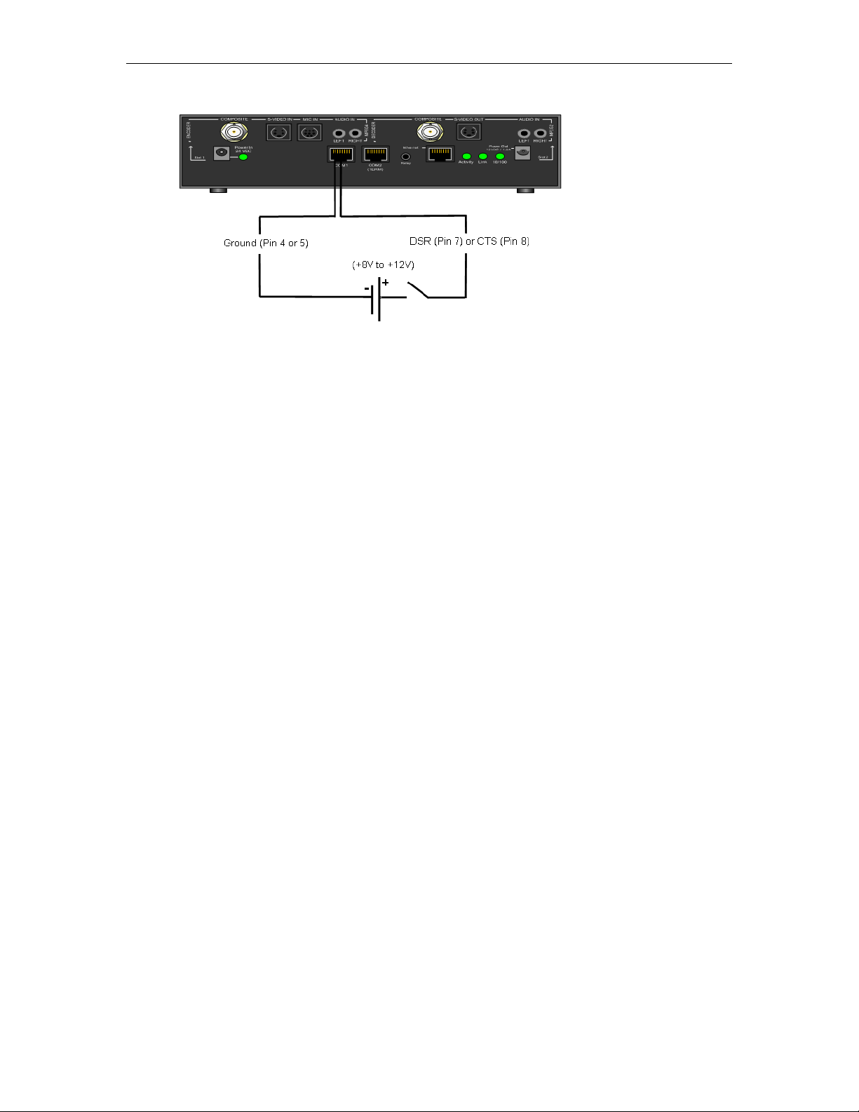
VB6000 Reference
Example 2
Connect the +12V Power Output of the VBrick through a switch to the event pin on the
COM1 port.
Example 3
Connect COM1 output pin (pin1 RTS or pin2 DTR) through a switch to a COM1 event pin.
For this method to work, you must force the desired output pin (RTS or DTR) to On via
IWS:
T To force the desired output pin to On:
1. Go to the
2. Change COM1
3. Change
4. Change COM1
5. Click
Configuration: Passt hrough page in IWS.
Passthrough State to Responder and click Apply.
RTS/DTR Control to Force On and click Apply.
Passthrough State to Disabled and click Apply.
Save Config when done.
VBrick Appliance Getting Started Guide 73

74 © 2008 VBrick Systems, Inc.

Index
Numerics
1. Connect an Input Audio/Video Source 3
2. Connect to the IP Network 4
3. Power-on the Appliance 4
4. Set the IP Address 4
5. Verify Operation 6
A
Accessories 27
Assigning Multicast Addresses 22
Audio In and Audio Out 69
Audio 20
B
Billboard 46
Billboard 30
C
Command Line Interface (CLI) 13
Conference Guide 47
Connecting with HyperTerminal 49
Current Models 65
E
Editing Configuration Parameters 62
Embedded Web Browser 30
Ethernet IP 24
Ethernet Port 68
Event Triggering 72
L
Logout 38
M
Making Changes 36
Menu Options 35
MPEG-2 Delay 19
MPEG-2 Encoder Compression 17
MPEG-2 17
Multiple Applies 39
N
Navigating the Top-Level Commands 61
Network Jitter 24
Network 22
O
One-Way Broadcast and Desktop Streaming 25
Other Editing Keys 64
Overview 9, 11
P
Passthrough Port Interface (COM 1) 67
Picture In Picture 46
Power In Entry Interface 68
Power Out Exit Interface 68
R
Reference Distance 18
F
Front Panel Edit 41
Front Panel Editing with the IR Remote Control
12
G
Group of Pictures (GOP) 18
H
How Passthrough Works 28
I
Integrated Web Server 11
Interfaces 67
Interrelationship 18
IP Address Configuration using Host Names 22
VBrick Appliance Getting Started Guide 75
S
Selecting Parenthetical Items 63
Serial Port Passthrough
Telnet Feature 29
Set the IP Address with HyperTerminal 5
Set the IP Address with the Remote Control 5
Setting System Date and Time 63
Simple Network Management Protocol (SNMP)
14
Streaming Video Basics 17
System Updates 9
T
Telnet 14
U
Understanding I, B, P Frames, Delay, and Synchronization
17

Using Apply, Revert, and Defaults 38
V
VB6000 65
VB6000 Reference 65
VB6000 VBSSM 65
VBDirectory 12
VBrick Video Stream Handling 24
Video 17
Video-In and Video-Out (Composite) 68
Video-In and Video-Out (S-Video Interface) 69
W
Welcome Screen 34
Z
AudioMate In 69
Connecting with Telnet 50
IP Differentiated Services (Diffserv) 23
Picture-in-Picture 30
Program Guide 48
Serial Port Passthrough 27
Setting and Changing Parameters 62
Two-way interactive Conferencing 26
Typical Applications 24
Installing a System Update 9
76 Index


VBrick Systems, Inc.
12 Beaumont Road
Wallingford, Connecticut 06492, USA
 Loading...