

Page 1
TM
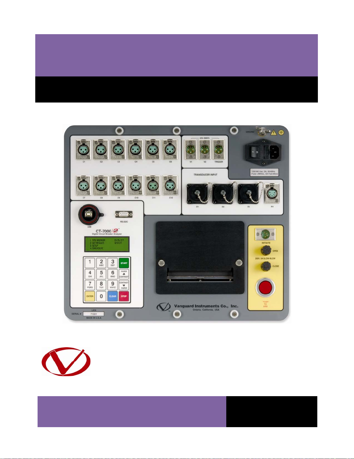
CT-7000 S2
DIGITAL CIRCUIT BREAKER ANALYZER
USER’S MANUAL
Vanguard Instruments Company, Inc.
1520 S. Hellman Ave.
Ontario, California 91761, USA
TEL: (909) 923-9390
FAX: (909) 923-9391
February 2011
Revision 2
Page 2

CT-7000 S2 USER’S MANUAL REV 2
SAFETY SUMMARY
FOLLOW EXACT OPERATING PROCEDURES
Any deviation from the procedures described in this User’s Manual may create one or more
safety hazards, may damage the CT-7000 S2, or cause errors in the test results. Vanguard
Instruments Company, Inc. assumes no liability for unsafe or improper use of the CT-7000 S2.
All safety precautions provided in this manual must be observed during all phases of testing
including test preparation, test lead connection, actual testing, and test lead disconnection.
SAFETY WARNINGS AND CAUTIONS
Only trained operators shall use the CT-7000 S2. All devices under test shall be off-line and fully
isolated. Do not perform test procedures or service unless another person is also present who
is capable of rendering aid and resuscitation.
DO NOT MODIFY TEST EQUIPMENT
To avoid the risk of introducing additional or unknown hazards, do not install substitute parts or
perform any unauthorized modification to any CT-7000 S2 test unit. To ensure that all designed
safety features are maintained, it is highly recommended that repairs be performed only by
Vanguard Instruments Company factory personnel or by an authorized repair service provider.
Unauthorized modifications can cause safety hazards and will void the manufacturer’s
warranty.
WARNING
Do not remove test leads during a test. Failure to heed this warning can result in electrical
shock to personnel and damage to the equipment.
i
Page 3

REV 2 CT-7000 S2 USER’S MANUAL
TABLE OF CONTENTS
CONVENTIONS USED IN THIS DOCUMENT ..................................................................................... 1
1.0 INTRODUCTION .................................................................................................................. .. 2
1.1 General Description and Features ................................................................................... 2
1.2 Technical Specifications ................................................................................................... 4
1.3 CT-7000 S2 Controls and Indicators ................................................................................. 5
2.0 PRE-TEST SETUP ................................................................................................................... 7
2.1 Operating Voltages .......................................................................................................... 7
2.2 LCD Screen Contrast Control ............................................................................................ 7
2.3 Printer Paper Control ....................................................................................................... 8
2.4 Printer Paper .................................................................................................................... 8
3.0 OPERATING PROCEDURES ................................................................................................... 9
3.1 Cable Connections ........................................................................................................... 9
3.1.1. Contact Cable Connections ...................................................................................... 9
3.1.2. Initiate Cable Connections ..................................................................................... 11
3.1.3. Analog and Digital Voltage Monitoring Connections ............................................. 13
3.1.4. External Trigger Input Connections ........................................................................ 14
3.1.5. Digital Transducer Connection ............................................................................... 15
3.1.6. Resistor Type Transducer Connection .................................................................... 16
3.1.7. Pre-Test Setup ................................................................................................................ 17
3.1.8. Entering Test Record Header Information ............................................................. 17
3.1.9. Setting the Clock ..................................................................................................... 20
3.1.10. Configuring the Automatic Printing Feature .......................................................... 21
3.1.11. Setting the Units of Measure ................................................................................. 22
3.1.12. Setting the Open Timing Analysis Points ................................................................ 23
3.1.13. Selecting the Contact Cycle Reading Frequency .................................................... 27
3.1.14. Configuring the Channel Settings ........................................................................... 30
3.1.15. Configuring the Contact Filter Settings .................................................................. 32
3.1.16. Configuring the Transducer Encoder Filter Setting ................................................ 34
3.1.17. Configuring the Digital Rotary Transducer Settings ............................................... 36
3.1.18. Configuring the Resister Type Transducer Settings ............................................... 38
3.2 Performing Circuit Breaker Timing Tests ....................................................................... 45
3.2.1. Timing an OPEN Operation ..................................................................................... 46
3.2.2. Timing a CLOSE-OPEN Operation Using Contact Channel #1 ................................. 49
3.2.3. Timing an OPEN-CLOSE-OPEN Operation ............................................................... 52
3.2.4. Running CT-7000 S2’s in Tandem ........................................................................... 56
3.2.5. Printing or Viewing Timing Results ......................................................................... 57
3.3 Working with Test Records ............................................................................................ 67
3.3.1. Saving a Timing Record in Flash EEPROM .............................................................. 67
3.3.2. Printing a Test Record Directory ............................................................................ 68
3.3.3. Recalling a Test Record from the Flash EEPROM ................................................... 70
3.3.4. Deleting Test Records from the Flash EEPROM ..................................................... 72
3.4 Working With Test Plans ................................................................................................ 75
ii
Page 4

CT-7000 S2 USER’S MANUAL REV 2
3.4.1. Recalling a Breaker Test Plan for Use ..................................................................... 75
3.4.2. Printing a Directory of Test Plans Stored in the CT-7000 S2’s Memory ................. 78
3.4.3. Printing a Breaker Test Plan ................................................................................... 80
4.0 DIAGNOSTICS, VERIFICATION, AND TROUBLESHOOTING ................................................. 84
4.1 Performing a Slow-Close Test ........................................................................................ 84
4.2 Performing a Transducer Self-Test ................................................................................ 86
4.3 Testing the Cable Hookups ............................................................................................ 87
4.4 Printing Raw Test Record Data ...................................................................................... 88
4.5 Troubleshooting Guide .................................................................................................. 90
5.0 APPENDICES ....................................................................................................................... 92
5.1 APPENDIX A – ITE Model 14.4K Circuit Breaker Timing Charts and Reports ................. 92
5.2 APPENDIX B – Siemens TCP Breaker Velocity Calculation ............................................. 97
5.3 APPENDIX C – Siemens SPS2 Breaker Velocity Calculation ........................................... 98
5.4 APPENDIX D – CT-7000 S2 Test Plan for Siemens SPS2 ................................................. 99
5.5 APPENDIX E – CT-7000 S2 Transducer Illustrations ..................................................... 100
LIST OF TABLES
Table 1. CT-7000 S2 Technical Specifications ................................................................................. 4
Table 2. Functional Descriptions of CT-7000 S2 Controls and Indicators ....................................... 6
Table 3. Descriptions of Tabulated Test Results Elements ........................................................... 60
iii
Page 5

REV 2 CT-7000 S2 USER’S MANUAL
LIST OF FIGURES
Figure 1. CT-7000 S2 Controls and Indicators ................................................................................. 5
Figure 2. CT-7000 S2 Operating Voltage Setting Switch ................................................................. 7
Figure 3. Typical 3-Phase Circuit Breaker Connections .................................................................. 9
Figure 4. Typical Connections for Series Contact Circuit Breaker ................................................ 10
Figure 5. Typical DC Trip and DC Close Control Circuit Connection ............................................. 11
Figure 6. Typical DC Trip and AC Close Control Circuit Connection .............................................. 12
Figure 7. Typical Analog and Digital Voltage Monitoring Connections ........................................ 13
Figure 8. Typical External Trigger Input Cable Connections ......................................................... 14
Figure 9. Typical Digital Transducer Connection .......................................................................... 15
Figure 10. Typical Resistor Type Transducer Connection ............................................................. 16
Figure 11. Typical 50 Hz Tabulated Test Results ........................................................................... 29
Figure 12. Typical 60 Hz Tabulated Test Results ........................................................................... 29
Figure 13. Contact Filter Setting Illustrations ............................................................................... 33
Figure 14. Sample Resistor Type Transducer Setup Directory ..................................................... 43
Figure 15. Sample Timing Report Using a Resistor Type Transducer ........................................... 44
Figure 16. Typical O-C-O Test Results Graph ................................................................................ 54
Figure 17. Typical Tabulated Test Results Printout for an O-C-O Operation ................................ 55
Figure 18. Typical Initiate and Trigger Connections for Operating Two CT-7000 S2's in Tandem 56
Figure 19. Typical Tabulated Test Results Printout for a CLOSE Operation ................................. 59
Figure 20. Typical Test Results Graph (CB CLOSE Test) ................................................................ 61
Figure 21. Expansion Graph from 0ms to 300ms (CB CLOSE Test) ............................................... 62
Figure 22. Typical O-C-O Test Results Graph ................................................................................ 63
Figure 23. Typical Tabulated Test Results Printout for an O-C-O Operation ................................ 64
Figure 24. Graphical Interpretation of an OPEN Timing Shot ....................................................... 65
Figure 25. Graphical Interpretation of a CLOSE Timing Shot ........................................................ 65
Figure 26. Graphical Interpretations of an OPEN-CLOSE and CLOSE-OPEN Timing Shot ............. 66
Figure 27. Sample Test Record Directory Printout ....................................................................... 69
Figure 28. Typical Test Results Printout with Pass/Fail Indicators ............................................... 77
Figure 29. Typical Test Plan Directory Printout ............................................................................ 79
Figure 30. Typical Breaker Test Plan Printout ............................................................................... 81
Figure 31. Siemens SPS2 121 CLOSE Timing Illustration ............................................................... 82
Figure 32. Siemens SPS2 121 OPEN Timing Illustration ................................................................ 83
Figure 33. Typical Slow-Close Test Results Printout ..................................................................... 85
Figure 34. Partial Data Points Printout ......................................................................................... 89
iv
Page 6
CT-7000 S2 USER’S MANUAL REV 2
CONVENTIONS USED IN THIS DOCUMENT
This document uses the following conventions:
• A key or switch on the CT-7000 S2 is indicated as [KEY] and [SWITCH].
Menu options are referenced as (MENU OPTION).
•
Screen and menu names are referenced as “SCREEN/MENU NAME”.
•
The terms “test record” and “test shot” are used interchangeably.
•
• CT-7000 S2 LCD screen output is shown as:
1. OPTION 1
2. OPTION 2
3. OPTION 3
4. OPTION 4
• When instructions are provided, the menu item that should be selected is shown in bold as
shown below (option 3 should be selected):
1. OPTION 1
2. OPTION 2
3. OPTION 3
4. OPTION 4
• Warning messages are indicated as:
Warning message
WARNING
• Important notes are indicated as:
Note details
NOTE
1
Page 7

REV 2 CT-7000 S2 USER’S MANUAL
1.0 INTRODUCTION
1.1 General Description and Features
The CT-7000 S2 is Vanguard’s third generation, stand-alone, microprocessor-driven EHV circuitbreaker analyzer. This inexpensive and easy to use analyzer is available in models with either 3
(CT-7000-3 S2), 6 (CT-7000-6 S2), or 12 (CT-7000-12 S2) dry-contact inputs. The CT-7000 S2 can
fully analyze a circuit-breaker’s performance by testing the contact time, stroke, velocity, overtravel, and contact wipe. Contact-motion analysis can be performed for all breaker contact
operations (Open, Close, Open – Close, Close – Open, and Open – Close – Open). The CT-7000
S2’s timing window is selectable between 1-second, 10-second, or 20-second periods. The 10second and 20-second timing windows are ideal for timing long duration events such as circuitswitcher contact testing.
Contact Timing Inputs
Dry-contact input channels are used for timing circuit-breaker contacts. Each contact input
channel can detect main contact and insertion-resistor contact times in milliseconds and cycles.
Voltage Monitoring Inputs
One analog voltage input channel is dedicated to monitoring a circuit-breaker’s DC power
supply or coil voltage (0 – 255 volts, DC or peak AC). One digital voltage input channel is
dedicated to detecting the voltage on/off status (presence or absence) of an A/B switch.
Trip/Close Current Monitoring
A built-in Hall-effect current sensor records the Trip/Close current level and duration. The
breaker’s operating-coil current waveform duration (effectively, a performance "fingerprint" or
"current profile") can be used as a diagnostic tool for analyzing a breaker’s performance.
Breaker Stroke and Velocity
Three digital travel transducer channels are available on the CT-7000 S2 for measuring circuitbreaker velocity, stroke, over-travel, and bounce-back. Unlike other transducer types, the
digital transducer requires neither calibration nor setup. A breaker’s contact-velocity is
calculated based on the contact’s travel distance over a period of time. The CT-7000 S2 can also
perform a special “slow-close” test that can measure the circuit breaker contact touch and
contact wipe.
Resistor Type Transducer Input
One optional resistor type input channel is also available on the CT-7000 S2. This input channel
allows the unit to measure circuit-breaker motion by directly interfacing with resistive type
transducers. The transducer resistance ranges from 200 ohms to 10K Ohms.
Breaker Initiate Features
A built-in solid-state initiate device is used to operate a breaker from the CT-7000 S2. The
operational modes include Open, Close, Open – Close, Close – Open, and Open – Close – Open.
Multiple operations, such as Open – Close and Open – Close – Open, can be initiated by using
programmable delay time or by sensing a breaker’s contact condition.
2
Page 8

CT-7000 S2 USER’S MANUAL REV 2
Internal Test Record Storage
The CT-7000 S2 can store up to 150 test records in Flash EEPROM. Test records can be retrieved
and printed on the built-in thermal printer, or they can be transferred to a PC via the unit’s RS232C or USB interface.
Internal Breaker Test Plan Storage
The CT-7000 S2 can store up to 99 circuit-breaker test plans. Test plans are comprised of all
circuit-breaker performance specifications (stroke, velocity, and contact time). A test plan can
be used to immediately test a circuit-breaker. A pass/fail report is then generated by comparing
actual performance with the specifications in the stored test plan. Test plans can also be
generated on a PC and transferred to the CT-7000 S2 via the unit’s RS-232C or USB interface.
Computer Interface
The CT-7000 S2 can be computer-controlled via its RS-232C or USB interface. A Windows®
XP/Vista/7-compatible Breaker-Analysis software application is provided with each unit. Using
this software, circuit-breakers can be timed from the PC. Test records can be retrieved from the
CT-7000 S2 and then stored on the PC for future analysis and report generation. Circuit-breaker
test plans can also be created on the PC and transferred to the CT-7000 S2. Additionally, test
records can be exported in Microsoft® Excel format for further analysis.
Diagnostic Capabilities
The CT-7000 S2 can perform diagnostics on its internal electronics. Diagnostics can be
performed to verify contact cable connections and to test the travel transducer’s electronics.
User Interface
The CT-7000 S2 features a back-lit LCD screen (20 characters by 4 lines) that is viewable in both
bright sunlight and low-light levels. A rugged, 16-key, membrane keypad is used to control the
unit.
Built-in Thermal Printer
The CT-7000 S2’s built-in 4.5-inch wide thermal printer can print the breaker contact analysis
results in both tabular and graphic formats.
3
Page 9

REV 2 CT-7000 S2 USER’S MANUAL
1.2 Technical Specifications
Table 1. CT-7000 S2 Technical Specifications
TYPE Portable circuit-breaker analyzer
PHYSICAL SPECIFICATIONS 16”W X 11”H x 14”D (40.6 cm x 29.9 cm x 35.6 cm); Weight: less than 25 lbs (11.3 kg)
INPUT POWER 100 – 120 Vac or 200 – 240 Vac (selectable), 50/60Hz
DRY-CONTACT INPUT 3, 6 or 12 dry-input channels (depending on model). Each channel detects main and
TIMING WINDOWS 1-second, 10-seconds, or 20-seconds
TIMING RESOLUTIONS ±50 micro-seconds @ 1-second duration,
TIMING ACCURACY 0.05% of reading ±0.05 ms @ 1-second duration
DRY-CONTACT CHANNEL
PROTECTION
DRY-CONTACT DETECTION
RANGE
RESISTOR DETECTION RANGE 50 – 5,000 ohms
TRIGGER INPUT VOLTAGE Open/Close: 30 – 300V, DC or peak AC
VOLTAGE SENSING INPUT
RANGE
BREAKER OPERATIONS Initiate Open, Close, Open– Close, Close – Open, Open – Close – Open
BREAKER INITIATE CAPACITY 30A, 250Vac/dc max
INITIATE CURRENT READING
RANGE
DIGITAL TRAVEL TRANSDUCER
INPUTS
OPTIONAL RESISTOR TYPE
TRANSDUCER INPUT
CONTACT TRAVEL POINT
DIFFERENCE
DISPLAY Back-lit LCD Screen (20 characters by 4 lines); viewable in bright sunlight and low-light
PRINTER Built-in 4.5-inch wide thermal printer can print both graphic contact travel waveforms
INTERNAL TEST RECORD
STORAGE
COMPUTER INTERFACES One RS-232C port, One USB port
PC SOFTWARE Windows® XP/Vista/7-based Breaker-Analysis software is included with purchase price
SAFETY Designed to meet UL 6101A-1 and CAN/CSA C22.2 No 1010.1-92 standards
ENVIRONMENT Operating: -10°C to 50°C (+15°F to +122°F); Storage: -30°C to70°C (-22°F to +158°F)
HUMIDITY (MAX) 90% RH @ 40˚ C (104˚ F) non-condensing
ALTITUDE (MAX) 2000m (6562 ft) to fully safety specifications
OPTIONS Transportation case (available for the CT-7000 S2 and the travel transducers)
WARRANTY One year on parts and labor
insertion-resistor contacts
±500 micro-seconds @ 10-second duration,
±1.0 milli-seconds @ 20-second duration
All contact inputs are grounded until test; input channels are protected against static
discharge
Closed: less than 20 ohms;
Open: greater than 5,000 ohms
V1: analog input; 0 – 255V DC or peak AC; Sensitivity ±1V
V2: voltage presence/absence detector input; 30 – 300V DC or peak AC
One, non-contact, Hall-effect sensor, 0 – 20 amp range, dc to 5Khz
3 digital travel transducer channels; Linear range, 0.0 – 60.0 in (±0.01 in); Rotary
range: 0 – 360 degrees (±0.36 degrees)
200 Ohms – 10K Ohms
Measures “slow-close” contact-point distances; results can be printed
levels
and tabulated test results
Stores up to 150 test records and 99 test plans
The above specifications are valid at nominal operating voltage and at a
temperature of 25°C (77°F). Specifications may change without prior notice.
NOTE
4
Page 10
CT-7000 S2 USER’S MANUAL REV 2
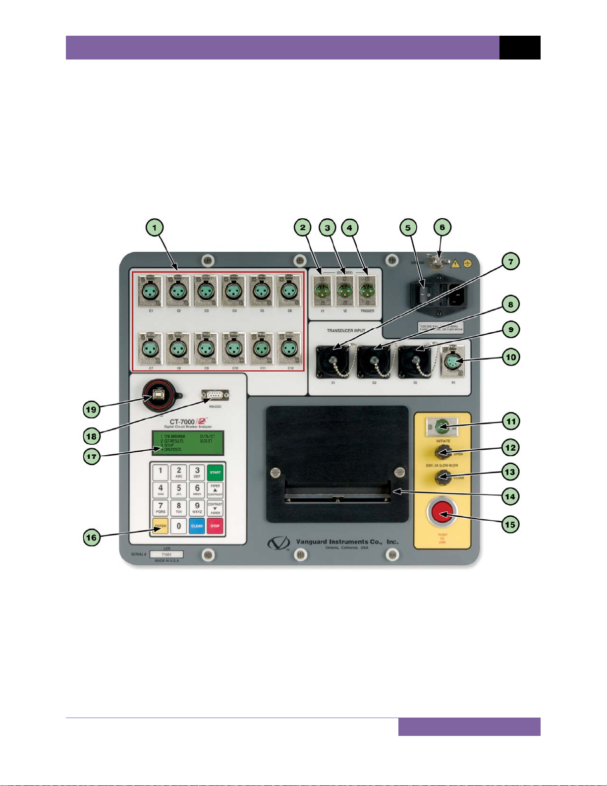
1.3 CT-7000 S2 Controls and Indicators
The CT-7000 S2’s controls and indicators are shown in Figure 1 below. A leader line with an
index number points to each control and indicator, which is cross-referenced to a functional
description in Table 2. The table describes the function of each item on the control panel. The
purpose of the controls and indicators may seem obvious, but users should become familiar
with them before using the CT-7000 S2. Accidental misuse of the controls will usually cause no
serious harm. Users should also be familiar with the safety summary found on the front page of
this User’s Manual.
Figure 1. CT-7000 S2 Controls and Indicators
5
Page 11

REV 2 CT-7000 S2 USER’S MANUAL
Table 2. Functional Descriptions of CT-7000 S2 Controls and Indicators
Item
Number
1
2
3
4
5
6
7, 8, 9
10
11
12
13
14
15
16
17
18
19
Panel Markings Functional Description
C1-C12 Female connectors for the contact channels. The CT-7000-12 S2 is pictured
with 12 channels.
0-300V
V1
0-300V
V2
0-300V
TRIGGER
100-120 Vac, 8A,
50-60Hz
GROUND Safety ground terminal.
D1, D2, D3
TRANSDUCER
INPUT
R1 5-pin connector. Resistor type transducer input. (Optional)
INITIATE 4-pin connector used for the switching circuit for op era ting the circuit breaker
OPEN
250V,
5A SLOW-BLOW
CLOSE
250V,
5A SLOW-BLOW
Built-in 4.5-inch wide thermal printer.
“PUSH” TO ARM Spring-loaded pushbutton switch. Press and hold to co mpl ete the Trip or Close
Rugged alpha-numeric membrane keypad.
Back-lit LCD screen (20 characters by 4 lines); viewable in bright sunlight and
RS-232C RS-232C serial computer interface port.
USB USB computer interface port.
3-pin connector. V1 voltage input channel is dedica ted to mon i toring circui t
breaker DC power supply o r co il voltages. Voltage sensing range is from 0-255
volts, dc or pe ak ac.
3-pin connector. V2 voltage input channel is dedicated to detecting voltage
on/off status (present or absent) of an A/B switch. Voltage input ranges from
0-300 volts, dc or peak ac.
3-pin connector. Triggers voltage input for external trigger application. Voltage
levels ranging from 30 to 300 V, dc or peak ac.
Power plug and power switch. Built-in 12 Ampe re circuit breaker.
16-pin connectors. Digital travel transducer input channels.
under test.
Open circuit fuse: 5 Ampere, 250V, SLOW-BLOW.
Close circuit fuse: 5 Ampere, 250V, SLOW-BLOW.
circuits for breaker tests.
low-light levels.
6
Page 12
CT-7000 S2 USER’S MANUAL REV 2
2.0 PRE-TEST SETUP
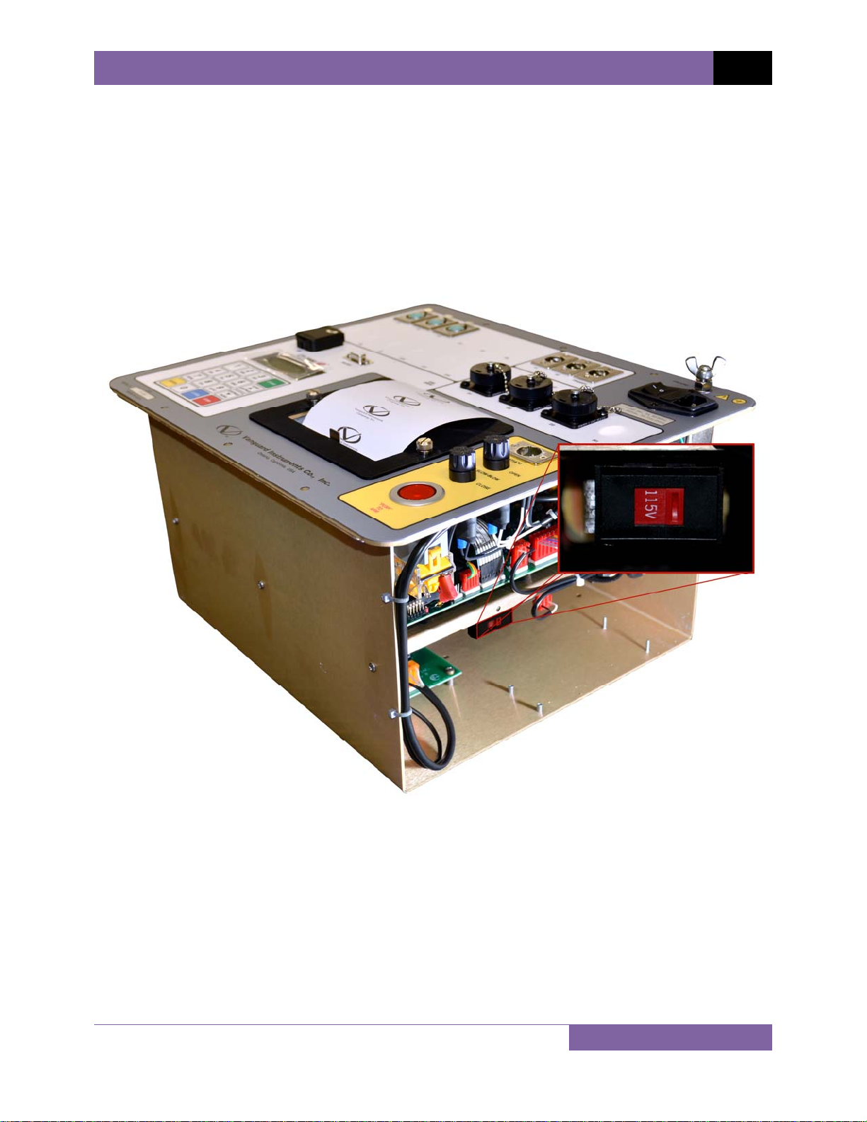
2.1 Operating Voltages
The CT-7000 S2’s operating voltage is selectable between 110-120 Vac, 50/60 Hz and 220-240
Vac, 50/60 Hz. In older production models of the CT-7000 S2, the operating voltage is set by the
voltage selection switch as shown in Figure 2. To change the voltage setting, remove the CT7000 S2 from its enclosure, locate the voltage setting switch on the right side of the unit, and
set the new operating voltage. Newer production models of the CT-7000 S2 can auto-sense the
voltage and do not have a voltage selection switch.
Figure 2. CT-7000 S2 Operating Voltage Setting Switch
2.2 LCD Screen Contrast Control
To increase the LCD screen contrast, press and hold the
[PAPER ∧ Contrast] key for two
seconds. Release the button when the desired contrast level has been reached.
To decrease the LCD screen contrast, press and hold the [PAPER ∨ Contrast] key for two
seconds. Release the button when the desired contrast level has been reached.
7
Page 13

REV 2 CT-7000 S2 USER’S MANUAL
2.3 Printer Paper Control
To advance the thermal printer paper, press and release the [PAPER ∧ Contrast] key.
To retract the thermal printer paper, press and release the [PAPER ∨ Contrast] key.
2.4 Printer Paper
The CT-7000 S2’s built-in thermal printer uses 4.5-inch wide thermal paper for printing test
results. To maintain the highest print quality and to avoid paper jams, the use of thermal paper
supplied by Vanguard Instruments Company is highly recommended. Additional paper can be
ordered from the following sources:
Vanguard Instruments Co, Inc.
1520 S. Hellman Avenue
Ontario, CA 91761
Tel: 909-923-9390
Fax: 909-923-9391
Part Number: VIC TP-4 paper
BG Instrument Co.
13607 E. Trent Avenue
Spokane, WA 99216
Tel: 509-893-9881
Fax: 509-893-9803
Part Number: VIC TP-4 paper
2.5 Replacing the Thermal Printer Paper
The roll of thermal paper is housed inside a dispenser underneath the printer cover. To replace
the paper, follow the steps below:
• Unscrew the two large printer cover screws and remove the printer cover.
• Remove the leftover thermal paper roll from the paper holder.
• Unroll the new thermal paper roll.
• Feed the thermal paper into the slot between the paper pocket and the rubber roller.
The printer will automatically pull the paper under the thermal head.
• Place the paper roll into the paper holder.
• Lift the thermal head and align the thermal paper if necessary.
• Re-install the printer cover.
Thermal paper has a chemical coating on one side of the paper. This side should be
facing the thermal print head. Incorrect paper loading may result in blank output on
NOTE
the thermal paper.
The thermal paper will show a red stripe to indicate that the roll is about to run out
of paper.
8
Page 14
CT-7000 S2 USER’S MANUAL REV 2
3.0 OPERATING PROCEDURES
3.1 Cable Connections
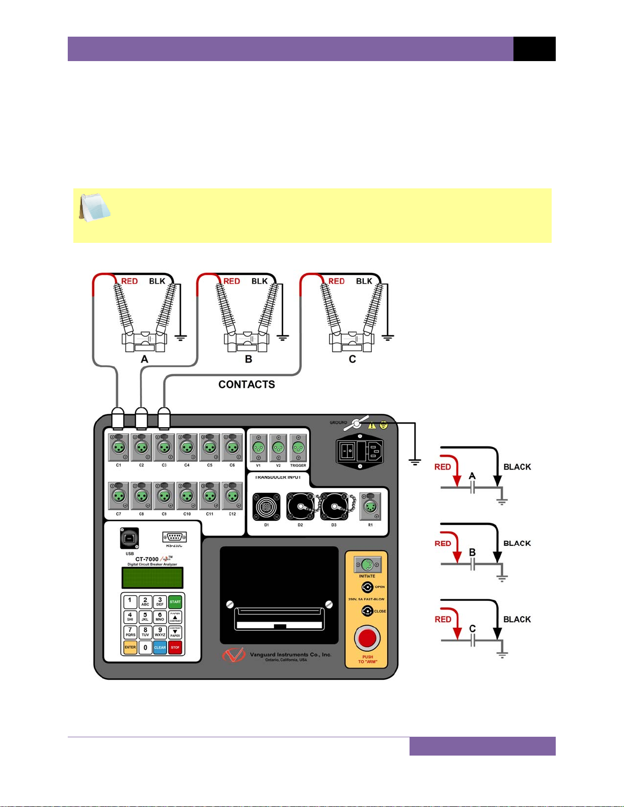
3.1.1. Contact Cable Connections
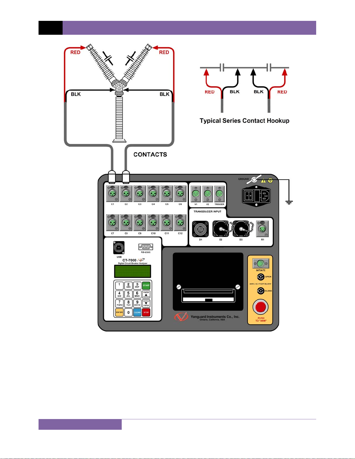
A typical contact cable connection to a circuit breaker is shown in Figure 3. Red and black clips
are connected across the circuit contact phases A, B, and C. A typical circuit breaker with series
contacts is shown in Figure 4.
It is advisable to ground one side of the contacts for most testing purposes. If a
breaker is floating or un-grounded, ensure that the contact channel inputs are
NOTE
protected against static discharge.
Figure 3. Typical 3-Phase Circuit Breaker Connections
9
Page 15
REV 2 CT-7000 S2 USER’S MANUAL
Figure 4. Typical Connections for Series Contact Circuit Breaker
10
Page 16
CT-7000 S2 USER’S MANUAL REV 2
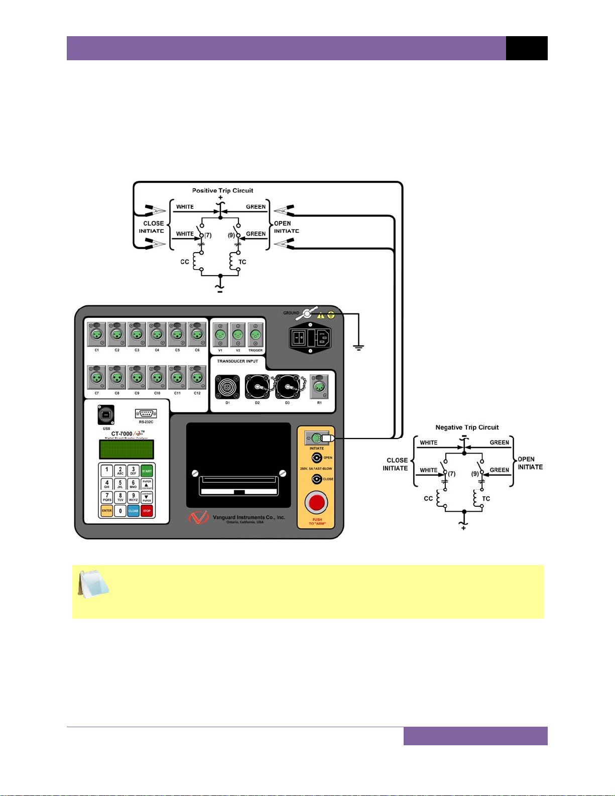
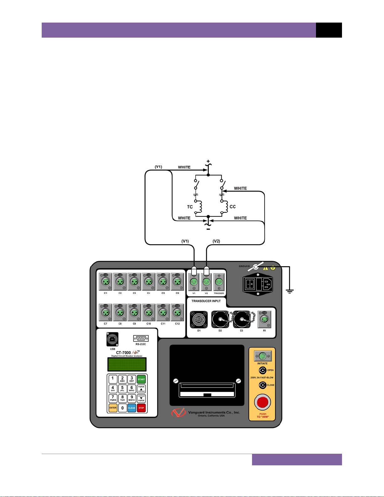
3.1.2. Initiate Cable Connections
The CT-7000 S2 can trip or close breakers through a solid-state device operating on any AC or
DC control voltage ranging from 10 to 300 Volts. Both the trip and close circuits are protected
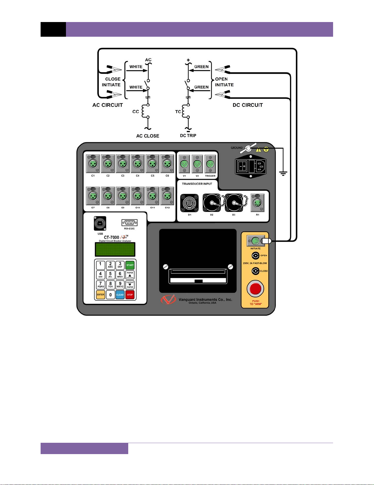
by 5 Ampere fuses. A typical DC trip and DC close control circuit connection is shown in Figure
5. A typical DC trip and AC close control circuit connection is shown in Figure 6.
NOTE
Figure 5. Typical DC Trip and DC Close Control Circuit Connection
Auxiliary switches, in series with the OPEN and CLOSE coil control circuit, are used to
interrupt the coil current.
11
Page 17
REV 2 CT-7000 S2 USER’S MANUAL
Figure 6. Typical DC Trip and AC Close Control Circuit Connection
12
Page 18
CT-7000 S2 USER’S MANUAL REV 2
3.1.3. Analog and Digital Vo ltage Monitoring Connections
The analog voltage input “V1” can monitor a breaker’s DC control voltage during an operation.
The analog voltage input records the nominal DC voltage at no load and the minimum DC
voltage while the Trip or Close coil is energized. The nominal and minimal voltage readings are
printed on a tabulated report, and the analog waveforms are plotted in graphical format. This
allows the user to see the breaker’s DC control voltage “dip” under load conditions and helps
detect problems such as a poor connection or an excessive voltage drop during operation.
Please note that the maximum voltage that can be recorded is 255 Vdc.
The digital voltage input channel “V2” can monitor the voltage status as “ON” or “OFF” states.
The voltage “ON” or “OFF” states are plotted on the graphical report. Typical analog (“V1”) and
digital (“V2”) voltage monitoring connections are shown in Figure 7.
Figure 7. Typical Analog and Digital Voltage Monitoring Connections
13
Page 19
REV 2 CT-7000 S2 USER’S MANUAL
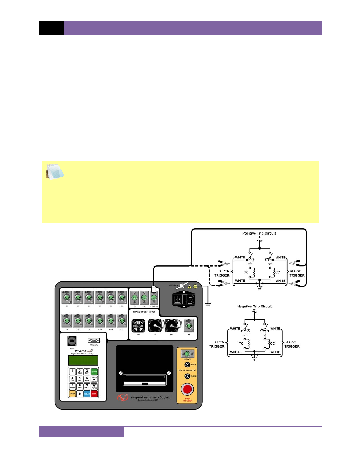
3.1.4. External Trigger Input Connections
The External Trigger Mode can be used to start recording data when the CT-7000 S2 senses a
voltage. A typical application for the External Trigger Mode is to time a circuit breaker in a Close
operation and to start timing only when the Close coil is energized, thus bypassing the 52X relay
delay time.
Since the 52X relay carries the Close coil current, the CT-7000 S2’s initiate cable must be
connected to the Close terminal as shown in Figure 5. The CT-7000 S2 will energize the 52X
relay to start the Close operation, which will then start the timing when the CT-7000 S2 senses
the voltage across the closing coil. Typical external trigger input connections are shown in
Figure 8.
Another application for the External Trigger is to start timing the breaker when the user trips or
closes the breaker remotely.
• The minimum trigger voltage is 30 Vac/dc. Maximum, continuous voltage is limited
to 300 Vac/dc. Different trigger voltages can be set at the factory by request.
NOTES
• The CT-7000 S2 will start looking for the external trigger voltage when the message
“AWAITING TRIGGER…” is displayed on the LCD screen. The external trigger
voltage must be sensed by the CT-7000 S2 within 15 seconds after the initiate
sequence has begun. The CT-7000 S2 will return to the “START-UP” menu if no
voltage is sensed.
14
Figure 8. Typical External Trigger Input Cable Connections
Page 20
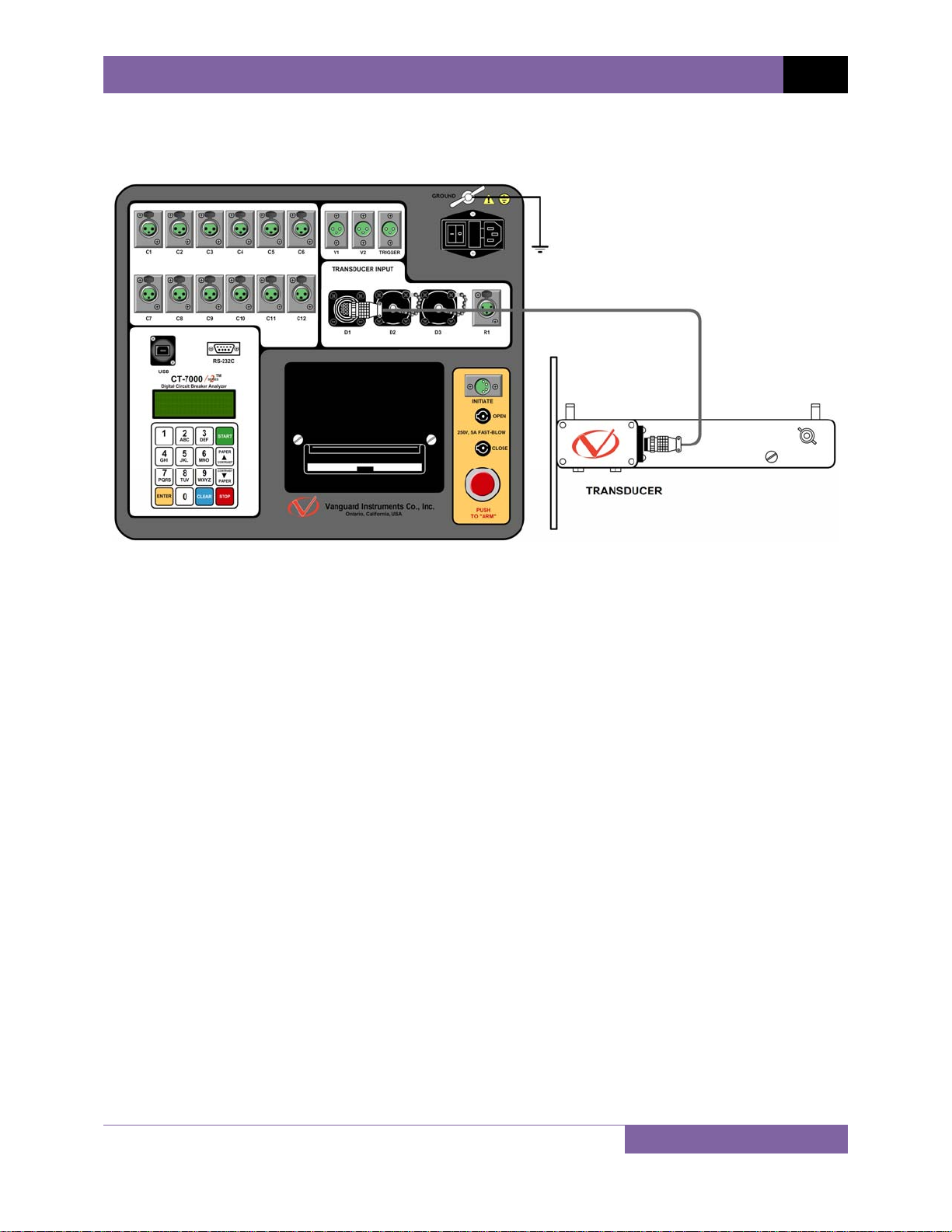
3.1.5. Digital Transducer Connection
A typical digital transducer connection is shown in Figure 9.
CT-7000 S2 USER’S MANUAL REV 2
Figure 9. Typical Digital Transducer Connection
15
Page 21
REV 2 CT-7000 S2 USER’S MANUAL
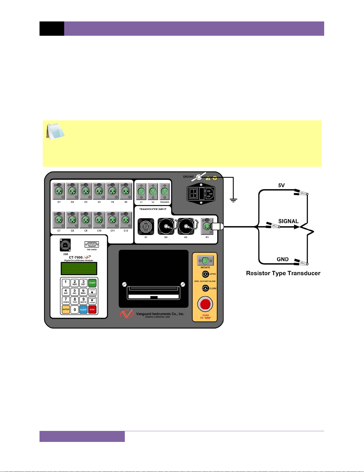
3.1.6. Resistor Type Transducer Connection
The CT-7000 S2 provides one channel for resistor type transducers. The transducer resistance
input can range from 200 Ohms to 10K Ohms. The CT-7000 S2 supplies a 5 Vdc reference
voltage to power the resistor type transducer. The sense voltage is translated into a travel
distance based on the transducer calibration parameters. The user is required to setup the
resistor transducer before performing a test. Up to nine transducer setups can be stored in the
CT-7000 S2’s internal memory. Once a transducer setup is stored, it can be recalled quickly
before running a test. A typical resistor type transducer connection is shown in Figure 10.
• When a resistor type transducer is used, the test results are shown as travel
transducer channel 1 (see Figure 15).
NOTES
• A 15-foot transducer cable with 3 quick disconnect clips is provided with each CT-
7000 S2. The 3 clips are labeled “+5V”, “Signal”, and “GND”.
• See section 3.1.18 for resistor type transducer calibration information.
16
Figure 10. Typical Resistor Type Transducer Connection
Page 22

CT-7000 S2 USER’S MANUAL REV 2
3.1.7. Pre-Test Setup
3.1.8. Entering Test Record Header Information
You can enter the test record header information before performing tests. The record header
includes identifying information such as the company, station, circuit, model number, etc. Once
the header information has been entered, it will apply to all subsequent test records. To enter
the header information:
a. When the unit is turned on and the firmware is loaded, you will be presented with the
“START-UP” menu as shown below:
1. TIME BRKR 02/03/11
2. GET RSLT 09:04:05
3. SETUP
4. DIAGNOSTICS
Press the [3] key (SETUP).
b. The following screen will be displayed:
1. ANALYSIS POINTS
2. MEASUREMENT UNITS
3. SAVE / RESTORE
4. NEXT PAGE
Press the [4] key (NEXT PAGE).
c. The following screen will be displayed:
1. SHOT DESCRIPTION
2. NUMBER OF CHANNELS
3. SET DATE & TIME
4. NEXT PAGE
Press the [1] key (SHOT DESCRIPTION).
17
Page 23

REV 2 CT-7000 S2 USER’S MANUAL
d. The following screen will be displayed:
COMPANY:
↑↓ TO POSITION
“ENTER” TO ACCEPT
Type the company name using the alpha-numeric keypad.
When pressing a key, the corresponding number on the key will be displayed first.
Pressing the key again will display the first letter on the key. Pressing the key again will
display the second letter on the key. For example, to type the letter “A”, you must press
[2] key twice. To erase the character at the cursor position, press the [CLEAR] key.
the
Press the
∨ Contrast]
[PAPER ∧ Contrast] key to move to the next character. Press the [PAPER
key to move to the previous character. Press the [ENTER] key when you
are done typing the company name.
e. The following screen will be displayed:
STATION:
↑↓ TO POSITION
“ENTER” TO ACCEPT
Type the station name using the alpha-numeric keypad and then press the [ENTER]
key.
f. The following screen will be displayed:
CIRCUIT:
↑↓ TO POSITION
“ENTER” TO ACCEPT
Type the circuit information using the alpha-numeric keypad and then press the
[ENTER] key.
g. The following screen will be displayed:
MANUFACTURER:
↑↓ TO POSITION
“ENTER” TO ACCEPT
Type the manufacturer name using the alpha-numeric keypad and then press the
[ENTER] key.
18
Page 24

h. The following screen will be displayed:
MODEL:
↑↓ TO POSITION
“ENTER” TO ACCEPT
Type the model information using the alpha-numeric keypad and then press the
[ENTER] key.
i. The following screen will be displayed:
SERIAL NUMBER:
↑↓ TO POSITION
“ENTER” TO ACCEPT
Type the serial number using the alpha-numeric keypad and then press the [ENTER]
key.
j. The following screen will be displayed:
CT-7000 S2 USER’S MANUAL REV 2
OPERATOR:
↑↓ TO POSITION
“ENTER” TO ACCEPT
Type the operator’s name using the alpha-numeric keypad and then press the [ENTER]
key. All header information will be saved, and you will be returned to the “START-UP”
menu.
19
Page 25

REV 2 CT-7000 S2 USER’S MANUAL
3.1.9. Setting the Clock
To set the CT-7000 S2’s internal clock:
a. Start from the “START-UP” menu:
1. TIME BRKR 02/03/11
2. GET RSLT 09:04:05
3. SETUP
4. DIAGNOSTICS
Press the [3] key (SETUP).
b. The following screen will be displayed:
1. ANALYSIS POINTS
2. MEASUREMENT UNITS
3. SAVE / RESTORE
4. NEXT PAGE
Press the [4] key (NEXT PAGE).
c. The following screen will be displayed:
1. SHOT DESCRIPTION
2. NUMBER OF CHANNELS
3. SET DATE & TIME
4. NEXT PAGE
Press the [3] key (SET DATE & TIME).
d. The following screen will be displayed:
ENTER
MM-DD-YY HH:MM:SS
Enter the month, date, time, hours, minutes, and seconds (in 24-hour format) using the
alpha-numeric keypad. When the last digit is entered, the clock will be set and you will
be returned to the “START-UP” menu.
20
Page 26
CT-7000 S2 USER’S MANUAL REV 2
3.1.10. Configuring the Automatic Printing Feature
The CT-7000 S2 can be configured to print graphs and tabulated results automatically after each
test. To configure the automatic printing feature:
a. Start from the “START-UP” menu:
1. TIME BRKR 02/04/11
2. GET RSLT 13:29:15
3. SETUP
4. DIAGNOSTICS
Press the [3] key (SETUP).
b. The following screen will be displayed:
1. ANALYSIS POINTS
2. MEASUREMENT UNITS
3. SAVE / RESTORE
4. NEXT PAGE
Press the [4] key (NEXT PAGE).
c. The following screen will be displayed:
1. SHOT DESCRIPTION
2. NUMBER OF CHANNELS
3. SET DATE & TIME
4. NEXT PAGE
Press the [4] key (NEXT PAGE).
d. The following screen will be displayed:
1. SET PRINT MODE
2. SET 50/60 Hz
Press the
[1] key (SET PRINT MODE).
e. The following screen will be displayed:
SET PRINT MODE:
1. AUTOMATIC PRINT
2. BY REQUEST ONLY
Press the
[1] key (AUTOMATIC PRINT) if you would like to automatically print tabulated
and graphic results after each test is performed.
Press the [2] key (BY REQUEST ONLY) to turn off automatic printing of test results.
Please see section 3.2.5 for instructions on how to manually print test results.
21
Page 27
REV 2 CT-7000 S2 USER’S MANUAL
3.1.11. Setting the Units of Measure
The CT-7000 S2 supports and displays both English and Metric calculations. You can switch
between the English and Metric systems using the steps below:
a. Start from the “START-UP” menu:
1. TIME BRKR 02/04/11
2. GET RSLT 13:08:25
3. SETUP
4. DIAGNOSTICS
Press the [3] key (SETUP).
b. The following screen will be displayed:
1. ANALYSIS POINTS
2. MEASUREMENT UNITS
3. SAVE / RESTORE
4. NEXT PAGE
Press the [2] key (MEASUREMENT UNITS).
c. The following screen will be displayed:
SELECT UNITS:
1. ENGLISH
2. METRIC
3. ROTARY ENCODER
Press the [1] key (ENGLISH) or the [2] key (METRIC) to select the corresponding
measurement system. The measurement system will be set and you will be returned to
the “START-UP” menu.
If the measurement system is changed, any relevant values in the working
memory will be automatically converted to the new system. Also, if retrieving
NOTE
a test record from the Flash EEPROM, all data will be converted to the new
measurement system. There is no need to re-run a test.
22
Page 28
CT-7000 S2 USER’S MANUAL REV 2
3.1.12. Setting the Open Timing Analysis Points
Two analysis points are used to calculate the velocity of the circuit breaker in the open
operation. To configure the OPEN timing analysis points:
a. Start from the “START-UP” menu:
1. TIME BRKR 02/04/11
2. GET RSLT 09:04:05
3. SETUP
4. DIAGNOSTICS
Press the [3] key (SETUP).
b. The following screen will be displayed:
1. ANALYSIS POINTS
2. MEASUREMENT UNITS
3. SAVE / RESTORE
4. NEXT PAGE
Press the [1] key (ANALYSIS POINTS).
c. The following screen will be displayed:
1. OPEN TIMING
2. CLOSE TIMING
3. PRINT SETTINGS
4. TEST PLANS
Press the [1] key (OPEN TIMING).
d. The following screen will be displayed:
OPEN ANALYSIS PT 1
1. PERCENT OF STROKE
2. DIST FROM CLOSE
3. CONTACT #1
1. PERCENT OF STROKE
Press the [1] key (PERCENT OF STROKE) to set the open analysis point #1 as a
percentage of the total stroke value.
Percentage of stroke is the distance based upon the percentage of the total
breaker’s stroke distance. The distance is always measured from the starting
NOTE
point at the fully closed position of the breaker contacts.
23
Page 29
REV 2 CT-7000 S2 USER’S MANUAL
The following screen will be displayed:
OPEN ANALYSIS PT 1
% OF TOTAL STROKE
VALUE: 00%
“ENTER” TO CONFIRM
Type the percentage value using the numeric keypad and then press the [ENTER]
key. Continue to step e.
2. DIST FROM CLOSE
Press the [2] key (DIST FROM CLOSE) to set the open analysis point #1 as a distance
from the contact’s close position.
The distance from close range is selectable from 00.0 inch to 99.99 inches or
from 0.0 to 999.0 millimeters. The distance is referenced from the contact’s
NOTE
closed position.
The following screen will be displayed:
OPEN ANALYSIS PT 1
DISTANCE FROM CLOSE
VALUE: 025.4 mm
“ENTER” TO CONFIRM
Type the distance value using the numeric keypad and then press the [ENTER] key.
Continue to step e.
3. CONTACT #1
Press the [3] key (CONTACT #1) to set the open analysis point #1 value equal to the
contact point #1 value. Continue to step e.
Contact point #1 is the distance from the contact’s closed position to the
point where it is in transition from the CLOSE to OPEN or the OPEN to CLOSE
NOTE
position.
24
Page 30
e. The following screen will be displayed:
OPEN ANALYSIS PT 2
1. PERCENT OF STROKE
2. DIST FROM CLOSE
3. CONTACT +/- TIME
1. PERCENT OF STROKE
Press the [1] key (PERCENT OF STROKE) to set the open analysis point #2 as a
percentage of the total stroke value. The following screen will be displayed:
OPEN ANALYSIS PT 2
% OF TOTAL STROKE
VALUE: 00%
“ENTER” TO CONFIRM
Type the percentage value using the numeric keypad and then press the [ENTER]
key. The analysis points will be set and you will be returned to the “START-UP”
menu.
CT-7000 S2 USER’S MANUAL REV 2
2. DIST FROM CLOSE
Press the [2] key (DIST FROM CLOSE) to set the open analysis point #2 as a distance
from the contact’s close position. The following screen will be displayed:
OPEN ANALYSIS PT 2
DISTANCE FROM CLOSE
VALUE: 127.0 mm
“ENTER” TO CONFIRM
Type the distance value using the numeric keypad and then press the [ENTER] key.
The analysis points will be set and you will be returned to the “START-UP” menu.
3. CONTACT +/- TIME
Press the [3] key to select the CONTACT +/- TIME option. The following screen will
be displayed:
OPEN ANALYSIS PT 2
1. CONTACT PLUS TIME
2. CONTACT MINUS TIME
1. CONTACT PLUS TIME
Press the
[1] key to select the CONTACT PLUS TIME option.
For the contact plus time, the user enters the time (in milliseconds)
after the contact channel #1 made the transition from OPEN to CLOSE
NOTE
or CLOSE to OPEN to define the analysis point #2.
25
Page 31

REV 2 CT-7000 S2 USER’S MANUAL
The following screen will be displayed:
OPEN ANALYSIS PT 2
ENTER TIME FROM CH1
TIME (mS): 000.0
“ENTER” TO CONFIRM
Type the time value using the numeric keypad and then press the [ENTER] key.
The analysis points will be set and you will be returned to the “START-UP” menu.
2. CONTACT MINUS TIME
Press the [2] key to select the CONTACT MINUS TIME option.
For the contact minus time, the user enters the time (in milliseconds)
before the contact channel #1 makes the transition from OPEN to
NOTE
CLOSE or CLOSE to OPEN to define the analysis point #2.
The following screen will be displayed:
OPEN ANALYSIS PT 2
ENTER TIME FROM CH1
TIME (mS): 000.0
“ENTER” TO CONFIRM
NOTES
Type the time value using the numeric keypad and then press the [ENTER] key.
The analysis points will be set and you will be returned to the “START-UP” menu.
• Average velocity through the arc zone is calculated using the following formula:
V
= Distance / Time
avg
• The breaker contact velocity can be recalculated based on the data stored in the
memory after any new analysis points are selected. The user does NOT need to
operate the breaker again to acquire new contact velocity data after changing the
analysis points because the new velocity will be calculated from the travel data
stored in the memory from the last operation.
• For complex velocity calculations, the user can create a test plan using the
included CT-7000 S2 Breaker Analysis PC Software. The test plan can then be
downloaded to the CT-7000 S2 and recalled before running timing tests.
26
Page 32

CT-7000 S2 USER’S MANUAL REV 2
3.1.13. Selecting the Contact Cycle Reading Frequency
The contact time is printed on the tabulated test results printout in both milliseconds and
cycles. The cycle readings can be in 50 Hz or 60 Hz. You can select the preferred frequency using
the steps below:
a. Start from the “START-UP” menu:
1. TIME BRKR 02/04/11
2. GET RSLT 09:04:05
3. SETUP
4. DIAGNOSTICS
Press the
[3] key (SETUP).
b. The following screen will be displayed:
1. ANALYSIS POINTS
2. MEASUREMENT UNITS
3. SAVE / RESTORE
4. NEXT PAGE
Press the
[4] key (NEXT PAGE).
c. The following screen will be displayed:
1. SHOT DESCRIPTION
2. NUMBER OF CHANNELS
3. SET DATE & TIME
4. NEXT PAGE
Press the [4] key (NEXT PAGE).
d. The following screen will be displayed:
1. SET PRINT MODE
2. SET 50/60 Hz
Press the [2] key (SET 50/60 Hz).
e. The following screen will be displayed:
1. SET 50 Hz
2. Set 60 Hz
Press either the
[1] key (SET 50 Hz) or the [2] key (SET 60 Hz) to set the frequency to
the corresponding value.
27
Page 33

REV 2 CT-7000 S2 USER’S MANUAL
f. The following confirmation screen will be displayed:
60 Hz SET
Press any key to return to the “START-UP” menu. Sample tabulated test results are
shown in Figure 11 and Figure 12.
If the frequency value is changed, the cycle values are automatically recalculated by the CT-7000 S2.
NOTE
28
Page 34

CT-7000 S2 USER’S MANUAL REV 2
Frequency Set to 50 Hz
Cycle reading at 50 Hz
Figure 11. Typical 50 Hz Tabulated Test Results
Frequency set to 60 Hz
Cycle reading at 60 Hz
Figure 12. Typical 60 Hz Tabulated Test Results
29
Page 35

REV 2 CT-7000 S2 USER’S MANUAL
3.1.14. Configuring the Channel Settings
The CT-7000 S2 is available with 3, 6, or 12 contact inputs. Since most common timing
applications require the use of only 3 contact timing channels and one travel transducer
channel, there is no need to print data for more than 3 timing channels and one transducer
channel on the graphic and tabulated reports. The CT-7000 S2 is configured to print 3 contact
channels by default (channels 1, 2, and 3) and one transducer channel (transducer channel #1).
The default settings can be changed using the steps below:
a. Start from the “START-UP” menu:
1. TIME BRKR 02/04/11
2. GET RSLT 09:04:05
3. SETUP
4. DIAGNOSTICS
Press the [3] key (SETUP).
b. The following screen will be displayed:
1. ANALYSIS POINTS
2. MEASUREMENT UNITS
3. SAVE / RESTORE
4. NEXT PAGE
Press the [4] key (NEXT PAGE).
c. The following screen will be displayed:
1. SHOT DESCRIPTION
2. NUMBER OF CHANNELS
3. SET DATE & TIME
4. NEXT PAGE
Press the [2] key (NUMBER OF CHANNELS).
d. The following screen will be displayed:
NUMBER OF CHANNELS
1. 3 CONTACTS
2. 6 CONTACTS
3. 12 CONTACTS
The number of channels listed on this screen depends on the CT-7000 model.
For example, if your unit has only 3 channels (Model CT-7000 S2-3), only option
NOTE
1 (3 Contacts) will be available.
Press either the [1] key (3 CONTACTS) or the [2] key (6 CONTACTS) to select the
corresponding number of contact channels.
30
Page 36

e. The following screen will be displayed:
1. TRANSDUCER 1
2. TRANSDUCER 1,2
3. TRANSDUCER 1,2,3
Select the number of transducer channels by pressing either the [1], [2], or [3] key. The
configuration information will be saved and you will be returned to the “START-UP”
menu.
CT-7000 S2 USER’S MANUAL REV 2
31
Page 37

REV 2 CT-7000 S2 USER’S MANUAL
3.1.15. Configuring the Contact Filter Settings
The contact filter setting is applicable only for timing circuit breakers with insertion resistors.
Although the CT-7000 S2 automatically detects the contact time using its own algorithm, it also
allows the user to enter a custom filter value. The value can be between 1 and 300. A filter
setting of 1 allows the CT-7000 S2 to pick up the first contact transition time after the resistor
contact activity is detected. A filter setting of 300 allows the CT-7000 S2 to pick up the last
contact transition time after the resistor contact activity is detected. Use the steps below to set
the contact filter value:
a. Start from the “START-UP” menu:
1. TIME BRKR 02/04/11
2. GET RSLT 09:04:05
3. SETUP
4. DIAGNOSTICS
Press the [4] key (DIAGNOSTICS).
b. The following screen will be displayed:
1. SLOW CLOSE TEST
2. CHECK HOOKUP
3. TEST TRANSDUCER
4. NEXT PAGE
Press the [4] key (NEXT PAGE).
c. The following screen will be displayed:
1. PRINT DATA
2. ENCODER FILTER
3. CONTACT FILTER
Press the
[3] key (CONTACT FILTER).
d. The following screen will be displayed:
ENTER FILTER SETTING
(1 – 300)
CURRENT SETTING: 1
NEW SETTING?
Type the new filter value using the numeric keypad and then press the
[ENTER] key.
The contact filter value will be set and you will be returned to the “START-UP” menu.
The filter value will be reset to the automatic setting when the unit’s power is
cycled.
NOTE
32
Page 38

CT-7000 S2 USER’S MANUAL REV 2
Filter Setting @ 1 will select
this contact time
Filter Setting @ 1 will select
this contact time
Filter Setting @ 300 will
select this contact time
Figure 13. Contact Filter Setting Illustrations
Filter Setting @ 300 will
select this contact time
33
Page 39

REV 2 CT-7000 S2 USER’S MANUAL
3.1.16. Configuring the Transducer Encoder Filter Setting
In a typical 1-second timing record, the CT-7000 S2 records 20,000 data points for each of the
contact channels, digital transducer channels, voltage input channels, CT channel, DCR channel,
resistor transducer channel, and initiate current channel. In most circuit breaker timing
applications, the breaker activities end after 200 milliseconds. A common problem found in the
field is that after the breaker activities have ended, the CT-7000 S2 may record erroneous data
on the transducer channels due to vibration. The erroneous data may be due to the transducer
not being secured properly to the mounting plate or due to a poor linkage problem between
the transducer and the circuit breaker mechanism.
To address this problem, the CT-7000 S2’s transducer encoder filter setting can be used to stop
recording the transducer channel data after a specific time. This feature can filter out the
unwanted motion picked up by the transducer after the breaker activities have ended. The CT7000 S2’s default filter value is set to “No Filter” when the unit is powered on. Use the steps
below to change the transducer encoder filter setting:
a. Start from the “START-UP” menu:
1. TIME BRKR 02/04/11
2. GET RSLT 09:04:05
3. SETUP
4. DIAGNOSTICS
Press the [4] key (DIAGNOSTICS).
b. The following screen will be displayed:
1. SLOW CLOSE TEST
2. CHECK HOOKUP
3. TEST TRANSDUCER
4. NEXT PAGE
Press the
[4] key (NEXT PAGE).
c. The following screen will be displayed:
1. PRINT DATA
2. ENCODER FILTER
3. CONTACT FILTER
Press the [2] key (ENCODER FILTER).
34
Page 40

d. The following screen will be displayed:
ENTER FILTER TIME
(010 – 999)
Type the filter time (in milliseconds) using the numeric keypad, and then press the
[ENTER] key to return to the “START-UP” menu. The CT-7000 S2 will not record any
transducer encoder data after this time.
CT-7000 S2 USER’S MANUAL REV 2
35
Page 41

REV 2 CT-7000 S2 USER’S MANUAL
3.1.17. Configuring the Digital Rotary Transducer Settings
A rotary transducer requires the user to enter the defined linear distance in millimeters or
inches per one degree of rotary motion. Follow the steps below to configure the settings for a
digital rotary transducer:
a. Start from the “START-UP” menu:
1. TIME BRKR 02/04/11
2. GET RSLT 09:04:05
3. SETUP
4. DIAGNOSTICS
Press the
[3] key (SETUP).
b. The following screen will be displayed:
1. ANALYSIS POINTS
2. MEASUREMENT UNITS
3. SAVE / RESTORE
4. NEXT PAGE
Press the
[2] key (MEASUREMENT UNITS).
c. The following screen will be displayed:
SELECT UNITS
1. ENGLISH
2. METRIC
3. ROTARY ENCODER
Press the [3] key (ROTARY ENCODER).
d. The following screen will be displayed:
ROTARY ENCODER:
1. ENGLISH (In./deg)
2. METRIC (MM/deg)
1. ENGLISH (In./deg)
Press the [1] key to enter the rotary encoder linear distance per degree using
English units. The following screen will be displayed:
36
INCHES/DEGREE
5.535 In/Deg
Page 42

CT-7000 S2 USER’S MANUAL REV 2
Type the desired value using the numeric keypad. You can press the [CLEAR] key
to reset the value to 0.000 In/Deg. Press the [ENTER] key to save the new value.
You will be returned to the “START-UP” menu.
2. METRIC (MM/deg)
Press the [2] key to enter the rotary encoder linear distance per degree using Metric
units. The following screen will be displayed:
MM/DEGREE
12.70 MM/Deg
Type the desired value using the numeric keypad. You can press the [CLEAR] key
to reset the value to 0.000 MM/Deg. Press the [ENTER] key to save the new value.
You will be returned to the “START-UP” menu.
37
Page 43

REV 2 CT-7000 S2 USER’S MANUAL
3.1.18. Configuring the Resister Type Transducer Settings
The CT-7000 S2 provides one optional channel for a resistor type transducer. The transducer
must be configured before it can be used with the CT-7000 S2. Up to 9 resistor transducer
setups can be stored in the CT-7000 S2’s Flash EEPROM. When a resistive transducer is used
with the CT-7000 S2, it is shown as transducer #1 on the timing report as shown in Figure 15.
Creating a New Resistor Type Transducer Setup
Follow the steps below to create a new resistor type transducer setup:
a. Start from the “START-UP” menu:
1. TIME BRKR 02/07/11
2. GET RSLT 13:58:05
3. SETUP
4. DIAGNOSTICS
Press the [3] key (SETUP).
b. The following screen will be displayed:
1. ANALYSIS POINTS
2. MEASUREMENT UNITS
3. SAVE / RESTORE
4. NEXT PAGE
Press the [2] key (MEASUREMENT UNITS).
c. The following screen will be displayed:
SELECT UNITS:
1. ENGLISH
2. METRIC
3. ROT ENC 4.RES ENC
Option 4 (RES ENC) will be available only if the CT-7000 S2 unit has the optional
R1 channel installed.
NOTE
Press the [4] key (RES ENC).
d. The following screen will be displayed:
RESISTIVE ENCODER
1. CREATE NEW SETUP
2. LOAD SETUP
3. PRINT SETUP DIR
Press the
[1] key (CREATE NEW SETUP).
38
Page 44

e. The following screen will be displayed:
RESISTIVE ENCODER
1. ENGLISH (IN/Volt)
2. METRIC (MM/Volt)
Press the [1] key to enter the transducer travel distance per volt using English units, or
press the [2] key to enter the transducer travel distance per volt using Metric units.
f. The following screen will be displayed:
MOVE RES ENCODER TO
REFERENCE POSITION.
“ENTER” TO CONTINUE
Move the transducer to the reference position and press the [ENTER] key.
g. The following screen will be displayed:
CT-7000 S2 USER’S MANUAL REV 2
MOVE RES ENCODER A
KNOWN DISTANCE...
“ENTER” TO CONTINUE
Move the transducer a known distance and press the [ENTER] key.
h. The following screen will be displayed (the units of measure displayed will depend on
your choice in step e):
ENTER THE DISTANCE
MOVED:
IN
“ENTER” TO CONTINUE
Using the numeric keypad, enter the distance the transducer was moved and then press
the [ENTER] key.
i. The following screen will be displayed:
ENTER SETUP NOTE:
↑↓ TO POSITION
“ENTER” TO ACCEPT
If you prefer, you can enter a note to be associated with the setup using the alphanumeric keypad. Press the [ENTER] key when done typing.
39
Page 45

REV 2 CT-7000 S2 USER’S MANUAL
j. The following screen will be displayed:
ENTER SETUP NUMBER
TO SAVE (1-9):
Enter a setup number from 1 to 9 using the numeric keypad.
k. The following screen will be displayed:
“ENTER” TO SAVE
SETUP NUMBER 1
Press the [ENTER] key to save the setup.
If a setup already exists at the selected memory location, it will be over-ridden
by the new setup values.
NOTE
l. The following screen will be displayed while the setup is being saved:
SAVE IN PROGRESS
PLEASE WAIT...
The following screen will be displayed when the setup has been saved:
SETUP SAVED!
Press any key to return to the “START-UP” menu.
40
Page 46

CT-7000 S2 USER’S MANUAL REV 2
Loading a Resistor Type Transducer Setup
Follow the steps below to load a resistor type transducer setup:
a. Start from the “START-UP” menu:
1. TIME BRKR 02/07/11
2. GET RSLT 14:04:05
3. SETUP
4. DIAGNOSTICS
Press the [3] key (SETUP).
b. The following screen will be displayed:
1. ANALYSIS POINTS
2. MEASUREMENT UNITS
3. SAVE / RESTORE
4. NEXT PAGE
Press the [2] key (MEASUREMENT UNITS).
c. The following screen will be displayed:
SELECT UNITS:
1. ENGLISH
2. METRIC
3. ROT ENC 4.RES ENC
Option 4 (RES ENC) will be available only if the CT-7000 S2 unit has the optional
R1 channel installed.
NOTE
Press the [4] key (RES ENC).
d. The following screen will be displayed:
RESISTIVE ENCODER
1. CREATE NEW SETUP
2. LOAD SETUP
3. PRINT SETUP DIR
Press the
[2] key (LOAD SETUP).
e. The following screen will be displayed:
ENTER SETUP NUMBER
TO LOAD (1-9):
Type the setup number to load using the numeric keypad.
41
Page 47

REV 2 CT-7000 S2 USER’S MANUAL
If there is no setup stored in the selected memory location, the following
screen will be displayed:
NOTE
SETUP NOT FOUND
Press any key to return to the “START-UP” menu.
f. The following screen will be displayed:
SETUP NUMBER: 1
NOTE
ENGLISH
“ENTER” TO CONTINUE
Press the
[ENTER] key to load the selected setup.
g. The following screen will be displayed:
SETUP LOADED!
Press any key to return to the “START-UP” menu.
Printing a Resistor Type Transducer Setup Directory
You can print a directory of the stored resistor type transducer setups on the built-in thermal
printer using the steps below:
a. Start from the “START-UP” menu:
1. TIME BRKR 02/07/11
2. GET RSLT 14:05:06
3. SETUP
4. DIAGNOSTICS
Press the [3] key (SETUP).
b. The following screen will be displayed:
1. ANALYSIS POINTS
2. MEASUREMENT UNITS
3. SAVE / RESTORE
4. NEXT PAGE
Press the
42
[2] key (MEASUREMENT UNITS).
Page 48

c. The following screen will be displayed:
SELECT UNITS:
1. ENGLISH
2. METRIC
3. ROT ENC 4.RES ENC
Press the [4] key (RES ENC).
d. The following screen will be displayed:
RESISTIVE ENCODER
1. CREATE NEW SETUP
2. LOAD SETUP
3. PRINT SETUP DIR
Press the [3] key (PRINT SETUP DIR). The setup directory will be printed and you will be
returned to the “START-UP” menu. A sample resistor type transducer setup directory
printout is shown in Figure 14.
CT-7000 S2 USER’S MANUAL REV 2
Figure 14. Sample Resistor Type Transducer Setup Directory
43
Page 49

REV 2 CT-7000 S2 USER’S MANUAL
Resistive Type
Transducer Indicator
Figure 15. Sample Timing Report Using a Resistor Type Transducer
44
Page 50

CT-7000 S2 USER’S MANUAL REV 2
3.2 Performing Circuit Breaker Timing Tests
The CT-7000 S2 can initiate the breaker operation and perform a timing test on the following
operations:
• OPEN
• CLOSE
• OPEN-CLOSE
• CLOSE-OPEN
• OPEN-CLOSE-OPEN
The CT-7000 S2 can start the OPEN-CLOSE operations without a delay or by using a
programmable delay between the OPEN and CLOSE commands.
The CLOSE-OPEN operation can be started by the CT-7000 S2 using several options:
• Contact #1 CLOSE
The CT-7000 S2 can initiate a CLOSE command and then an OPEN command after
detecting the closing of the breaker’s contact. The CT-7000 S2 detects the closing of the
contact through contact channel #1. This option is recommended for the CLOSE-OPEN
operation since it truly represents when the circuit breaker closed and then opened.
• Set DELAY
The CT-7000 S2 can initiate a CLOSE command and then an OPEN command after a
programmable delay set in milliseconds.
• No DELAY
The CT-7000 S2 can initiate a CLOSE command and then an OPEN command without any
delay. Since the circuit breaker is in the OPEN state, the breaker’s 52B contact allows
the CLOSE coil to be energized, which can start the CLOSE command. When the circuit
breaker is making the transition from an OPEN state to a CLOSE state, the 52A contact
will close allowing the breaker to initiate the OPEN command.
The OPEN-CLOSE-OPEN operation can be initiated by the CT-7000 S2 by using a programmable
delay between each of the operations. The delays can be set between the OPEN to CLOSE
commands and between the CLOSE to OPEN commands.
45
Page 51

REV 2 CT-7000 S2 USER’S MANUAL
3.2.1. Timing an OPEN Operation
The CT-7000 S2 can time breakers with or without insertion resistors. The insertion resistance
can range from 10 to 5,000 Ohms. Any insertion resistance greater than 5,000 Ohms is detected
as an open circuit. The timing results will show the main contact time and the insertion resistor
contact time. Graphic reports will show the main contact and the resistor contact activities on
each of the channels. Use the steps below to time an OPEN operation.
a. When the unit is turned on and the firmware has been loaded, you will be presented
with the “START-UP” menu as shown below:
1. TIME BRKR 02/08/11
2. GET RSLT 14:15:16
3. SETUP
4. DIAGNOSTICS
Press the [1] key (TIME BRKR).
b. The following screen will be displayed:
INSERTION RESISTOR?
1. NO
2. YES
1. NO
Press the [1] key if you are timing a circuit breaker without insertion resistors.
Continue to step c.
2. YES
Press the [2] key if you are timing a circuit breaker with insertion resistors. The
following screen will be displayed:
RESISTOR VALUE:
1. LESS THAN 1000 OHM
2. 1000 to 2000 OHM
3. MORE THAN 2000 OHM
Select the resistance value by pressing the corresponding key (
[1], [2], or [3]).
Continue to step c.
46
Page 52

c. The following screen will be displayed:
TIMING WINDOW:
1. WINDOW = 1 SEC
2. WINDOW = 10 SEC
3. WINDOW = 20 SEC
Press the [1] key (WINDOW = 1 SEC).
The 1-second timing window is used for breaker timing. The 10 and 20-
second timing windows are used for long timing events such as for timing
NOTE
circuit-switchers.
d. The following screen will be displayed:
TRIGGER MODE:
1. INTERNAL TRIGGER
2. EXTERNAL TRIGGER
Press the [1] key (INTERNAL TRIGGER).
CT-7000 S2 USER’S MANUAL REV 2
e. The following screen will be displayed:
TIMING MODE:
1. OPEN 2. CLOSE
3. O-C 4. C-O
5. O-C-O
Press the [1] key (OPEN).
f. The following screen will be displayed:
Hold “ARM” until
test completes.
“START” to Begin
“STOP” to ABORT
Hold down the [ARM] switch and press the [START] key.
g. The following screen will be displayed:
TEST IN PROGRESS
Hold “ARM” until
test completes.
(Up to 25 seconds)
Continue to hold down the [ARM] switch until testing is finished. You will be returned
to the “START-UP” menu once testing is finished.
47
Page 53

REV 2 CT-7000 S2 USER’S MANUAL
• Please see section 3.2.5 for information about printing test results.
• The CT-7000 S2 can be configured to print tabulated and graphics reports
NOTES
automatically after performing a test. Please see section 3.1.10 for further
information.
48
Page 54

CT-7000 S2 USER’S MANUAL REV 2
3.2.2. Timing a CLOSE-OPEN Operation Using Contact Channel #1
The CLOSE-OPEN operation of a breaker simulates a condition where a breaker is closed on a
fault. There are three options when timing a CLOSE-OPEN operation:
1. Contact #1 CLOSE
The CT-7000 S2 will initiate a CLOSE operation. The open operation is then initiated after
contact channel #1 is closed. This option closes simulates the breaker closing on a fault
condition in the field.
2. Set DELAY
A delay from 10 to 500 ms can be set between the CLOSE command and the OPEN
command. The CT-7000 S2 will initiate the CLOSE operation and start the delay counter.
The OPEN operation will be initiated when the delay time has elapsed.
3. No DELAY
Both the CLOSE and OPEN commands are initiated by the CT-7000 S2 simultaneously.
The OPEN coil is energized when the OPEN auxiliary switch makes.
Follow the steps below to time a CLOSE-OPEN operation:
a. Start from the “START-UP” menu:
1. TIME BRKR 02/10/11
2. GET RSLT 09:04:05
3. SETUP
4. DIAGNOSTICS
Press the [1] key (TIME BRKR).
b. The following screen will be displayed:
INSERTION RESISTOR?
1. NO
2. YES
Press the
[1] key (NO).
c. The following screen will be displayed:
TIMING WINDOW:
1. WINDOW = 1 SEC
2. WINDOW = 10 SEC
3. WINDOW = 20 SEC
Press the [1] key (WINDOW = 1 SEC).
49
Page 55

REV 2 CT-7000 S2 USER’S MANUAL
d. The following screen will be displayed:
TRIGGER MODE:
1. INTERNAL TRIGGER
2. EXTERNAL TRIGGER
Press the [1] key (INTERNAL TRIGGER).
e. The following screen will be displayed:
TIMING MODE:
1. OPEN 2. CLOSE
3. O-C 4. C-O
5. O-C-O
Press the [4] key (C-O).
f. The following screen will be displayed:
C-O Second Trigger
1. Contact #1 CLOSE
2. Set DELAY
3. No DELAY
1. Contact #1 CLOSE
Press the [1] key if you would like the open operation to be initiated after contact
channel #1 is closed. Continue to step g.
2. Set DELAY
Press the [2] key to set a delay time between the CLOSE command and the OPEN
command. The following screen will be displayed:
C-O Delay in mS:
(10 – 500)
mSec
ENTER when done
Type the delay time using the numeric keypad and then press the [ENTER] key.
Continue to step g.
3. No DELAY
Press the
[3] key to initiate the CLOSE and OPEN commands simultaneously.
Continue to step g.
50
Page 56

g. The following screen will be displayed:
Hold “ARM” until
test completes.
“START” to Begin
“STOP” to ABORT
Hold down the [ARM] switch and press the [START] key.
h. The following screen will be displayed:
TEST IN PROGRESS
Hold “ARM” until
test completes.
(Up to 25 seconds)
Continue to hold down the [ARM] switch until testing is finished. You will be returned
to the “START-UP” menu once testing is finished.
CT-7000 S2 USER’S MANUAL REV 2
51
Page 57

REV 2 CT-7000 S2 USER’S MANUAL
3.2.3. Timing an OPEN-CLOSE-OPEN Operation
The OPEN-CLOSE-OPEN operation requires the user to enter two time delays (in milliseconds)
between the circuit breaker operations. The first delay is from the first OPEN command to the
CLOSE command, and the second delay is from the CLOSE command to the second OPEN
command. Follow the steps below to time an OPEN-CLOSE-OPEN operation:
a. Start from the “START-UP” menu:
1. TIME BRKR 02/10/11
2. GET RSLT 09:04:05
3. SETUP
4. DIAGNOSTICS
Press the [1] key (TIME BRKR).
b. The following screen will be displayed:
INSERTION RESISTOR?
1. NO
2. YES
Press the [1] key (NO).
c. The following screen will be displayed:
TIMING WINDOW:
1. WINDOW = 1 SEC
2. WINDOW = 10 SEC
3. WINDOW = 20 SEC
Press the [1] key (WINDOW = 1 SEC).
d. The following screen will be displayed:
TRIGGER MODE:
1. INTERNAL TRIGGER
2. EXTERNAL TRIGGER
Press the [1] key (INTERNAL TRIGGER).
e. The following screen will be displayed:
TIMING MODE:
1. OPEN 2. CLOSE
3. O-C 4. C-O
5. O-C-O
Press the [5] key (O-C-O).
52
Page 58

f. The following screen will be displayed:
O-C Delay in mS:
(10 – 350)
200 mSec
ENTER when done
Using the numeric keypad, enter the time for the delay between the first OPEN
command and the CLOSE command. Press the [ENTER] key.
g. The following screen will be displayed:
C-O Delay in mS:
(10 – 350)
200 mSec
ENTER when done
Using the numeric keypad, enter the time for the delay between the CLOSE command
and the second OPEN command. Press the [ENTER] key.
h. The following screen will be displayed:
CT-7000 S2 USER’S MANUAL REV 2
Hold “ARM” until
test completes.
“START” to Begin
“STOP” to ABORT
Hold down the [ARM] switch and press the [START] key.
i. The following screen will be displayed:
TEST IN PROGRESS
Hold “ARM” until
test completes.
(Up to 25 seconds)
Continue to hold down the [ARM] switch until testing is finished. You will be returned
to the “START-UP” menu once testing is finished. See Figure 16 and Figure 17 for a
sample O-C-O test results graph and tabulated test results printout, respectively.
53
Page 59

REV 2 CT-7000 S2 USER’S MANUAL
54
Figure 16. Typical O-C-O Test Results Graph
Page 60

CT-7000 S2 USER’S MANUAL REV 2
Figure 17. Typical Tabulated Test Results Printout for an O-C-O Operation
55
Page 61

REV 2 CT-7000 S2 USER’S MANUAL
3.2.4. Running CT-7000 S2’s in Tandem
Two or more CT-7000 S2’s can be used to time a circuit breaker in cases where more than 6
timing contact channels are required. A typical application is to use one CT-7000 S2 with 6
channels (CT-7000-6 S2) and one CT-7000 S2 with 3 channels (CT-7000-3) to create a 9 contact
timing apparatus. Use the steps below to configure the CT-7000 S2’s:
a. Connect the CT-7000-6 S2 to phase A and B of the circuit breaker.
b. Connect the CT-7000-3 S2 to phase C of the circuit breaker.
c. Connect the CT-7000-6 S2’s initiate cable to the breaker control circuit. This unit will
operate the circuit breaker.
d. Connect the CT-7000-3 S2’s external trigger cable to the OPEN coil for the OPEN test and
CLOSE coil for the CLOSE test. This unit will operate as a slave device.
e. Start running a test from the CT-7000-3 S2 using the EXTERNAL TRIGGER option.
f. Run a test from the CT-7000-6 S2 using the INTERNAL TRIGGER option.
The CT-7000-6 S2 will operate the circuit breaker and start the timing sequence. The CT-7000-3
S2 will start its timing sequence as soon as it senses the voltage applied to the breaker coil. The
timing report of the CT-7000-6 S2 will show the contact time of phase A and B. The timing
report of the CT-7000-3 S2 will show the contact time for phase C. If the results are downloaded
to a PC using the included software, the two reports can be combined to generate a 9-channel
test report.
Figure 18. Typical Initiate and Trigger Connections for Operating Two CT-7000 S2's in Tandem
56
Page 62

CT-7000 S2 USER’S MANUAL REV 2
3.2.5. Printing or Viewing Timing Results
Follow the steps below to print or view the timing results after performing a circuit breaker
timing test:
a. After performing a timing test you will be returned to the “START-UP” menu:
1. TIME BRKR 02/10/11
2. GET RSLT 09:04:05
3. SETUP
4. DIAGNOSTICS
Press the [2] key (GET RSLT).
b. The following screen will be displayed:
1. PRINT TEST RESULTS
2. PLOT FULL CHART
3. PLOT EXPANSION
4. PLOT 0 – 200MS
1. PRINT TEST RESULTS
Press the [1] key to view the test results on the screen or to print the tabulated test
results WITHOUT the graph. The following screen will be displayed:
SELECT PRINTER:
1. THERMAL PRINTER
2. DISPLAY RESULTS
Press the [1] key (THERMAL PRINTER) to print the tabulated test results on the
built-in thermal printer. The tabulated results will be printed, and you will be
returned to the “START-UP” menu. A typical tabulated results printout is shown in
Figure 19.
Press the
[2] key (DISPLAY RESULTS) to display the test results on the unit’s LCD
screen. The following screen will be displayed:
UP/DWN ARROWS TO
SCROLL RESULTS...
“STOP” TO EXIT
Press the
[PAPER ∧ Contrast] and [PAPER ∨ Contrast] keys to scroll
through the test results. Press the
[STOP] key to return to the “START-UP”
menu.
57
Page 63

REV 2 CT-7000 S2 USER’S MANUAL
2. PLOT FULL CHART
Press the [2] key to print the tabulated results WITH the full graph of the results.
You will be returned to the “START-UP” menu when printing is finished. A typical
test result graph is shown in Figure 20.
3. PLOT EXPANSION
Press the [3] key to print the tabulated results along with a time expansion plot of
the test results. The following screen will be displayed:
EXPANSION FROM:
“ENTER” TO CONFIRM
You will be asked to enter the start point for the expansion. The start point can be
selected in 100 millisecond increments by typing the first digit of the starting time.
For example, to select 500ms, simply press the [5] key. The screen will be updated
as shown:
EXPANSION FROM:
500MS
“ENTER” TO CONFIRM
Press the [ENTER] key.
The following screen will be displayed:
EXPANSION TO:
“ENTER” TO CONFIRM
Enter the end point for the expansion by typing the first digit of the 100 millisecond
increment. For example, to select 900ms, press the
[9] key. The screen will be
updated as shown:
EXPANSION TO:
900MS
“ENTER” TO CONFIRM
Press the [ENTER] key.
The graph expansion will be printed along with the tabulated test results. You will
be returned to the “START-UP” menu when printing is finished. A sample expansion
graph is shown in Figure 21.
58
Page 64

CT-7000 S2 USER’S MANUAL REV 2
4. PLOT 0 – 200MS
Press the [4] key to print the tabulated test results along with the graphic test
results from 0 – 200 milliseconds. The graph and tabulated results will be printed
on the thermal printer. You will be returned to the “START-UP” menu when printing
is finished.
Figure 19. Typical Tabulated Test Results Printout for a CLOSE Operation
59
Page 65

REV 2 CT-7000 S2 USER’S MANUAL
Table 3. Descriptions of Tabulated Test Results Elements
Item
Number
1
2
3
4
5
6
7
8
9
10
11
12
13
14
15
16
17
Description
Test record number and the date and time the test was performed.
Test record header information (Company, Station, Circuit, etc.).
Type of test performed (OPEN, CLOSE, O-C, C-O, or O-C-O).
Contact channel times shown in milliseconds and cycles.
Contact channel bounce times shown in milliseconds.
Contact channel wipe distances in inches.
Contact delta time in milliseconds. This is the difference between the slowest contact time and the
fastest contact time.
Breaker contact stroke in inches.
Contact velocity in feet per second.
Contact over-travel distance in inches.
Contact bounce-back distance in inches.
Contact velocity calculation points.
DC power supply nominal and minimum voltage (if DC power supply was monitored during testing).
Initiate current.
Timing shot duration.
Insertion time (if breaker had an insertion resistor) or “NO” if there was no resistor.
Trigger mode (Internal or External)
60
Page 66

CT-7000 S2 USER’S MANUAL REV 2
Figure 20. Typical Test Results Graph (CB CLOSE Test)
61
Page 67

REV 2 CT-7000 S2 USER’S MANUAL
Figure 21. Expansion Graph from 0ms to 300ms (CB CLOSE Test)
62
Page 68

CT-7000 S2 USER’S MANUAL REV 2
Figure 22. Typical O-C-O Test Results Graph
63
Page 69

REV 2 CT-7000 S2 USER’S MANUAL
Figure 23. Typical Tabulated Test Results Printout for an O-C-O Operation
64
Page 70

CT-7000 S2 USER’S MANUAL REV 2
Figure 24. Graphical Interpretation of an OPEN Timing Shot
Figure 25. Graphical Interpretation of a CLOSE Timing Shot
65
Page 71

REV 2 CT-7000 S2 USER’S MANUAL
Figure 26. Graphical Interpretations of an OPEN-CLOSE and CLOSE-OPEN Timing Shot
66
Page 72

CT-7000 S2 USER’S MANUAL REV 2
3.3 Working with Test Records
3.3.1. Saving a Timing Record in Flash EEPRO M
After performing a test, you can store the results in the CT-7000 S2’s Flash EEPROM. To save a
test record:
a. Start from the “START-UP” menu:
1. TIME BRKR 02/10/11
2. GET RSLT 14:16:18
3. SETUP
4. DIAGNOSTICS
Press the [3] key (SETUP).
b. The following screen will be displayed:
1. ANALYSIS POINTS
2. MEASUREMENT UNITS
3. SAVE / RESTORE
4. NEXT PAGE
Press the [3] key (SAVE / RESTORE).
c. The following screen will be displayed:
1. SAVE SHOT
2. RESTORE SHOT
3. SHOT DIRECTORY
4. ERASE SHOT
Press the [1] key (SAVE SHOT).
d. The following screen will be displayed:
SAVE SHOT #1
TEST:STATIC RES TEST
DATE: 03/11/10 13:26
“ENTER” TO PROCEED
Press the
[ENTER] key to save the test shot.
e. The following screen will be displayed:
SHOT SAVED
Press any key to return to the “START-UP” menu.
67
Page 73

REV 2 CT-7000 S2 USER’S MANUAL
3.3.2. Printing a Test Record Directory
You can print a directory of all the test records stored in the CT-7000 S2’s Flash EEPROM by
using the steps below:
a. Start from the “START-UP” menu:
1. TIME BRKR 02/10/11
2. GET RSLT 09:04:05
3. SETUP
4. DIAGNOSTICS
Press the [3] key (SETUP).
b. The following screen will be displayed:
1. ANALYSIS POINTS
2. MEASUREMENT UNITS
3. SAVE / RESTORE
4. NEXT PAGE
Press the [3] key (SAVE / RESTORE).
c. The following screen will be displayed:
1. SAVE SHOT
2. RESTORE SHOT
3. SHOT DIRECTORY
4. ERASE SHOT
Press the [3] key (SHOT DIRECTORY).
d. The following screen will be displayed:
1. SHORT DIRECTORY
2. FULL DIRECTORY
Press the
[1] key (SHORT DIRECTORY) to print a directory of the last ten shots stored in
the EEPROM. The short directory will be printed, and you will be returned to the
“START-UP” menu.
Press the
[2] key (FULL DIRECTORY) to print a directory of all the shots stored in the
EEPROM. The full directory will be printed, and you will be returned to the “START-UP”
menu.
A sample test record directory is shown in Figure 27.
68
Page 74

CT-7000 S2 USER’S MANUAL REV 2
Figure 27. Sample Test Record Directory Printout
69
Page 75

REV 2 CT-7000 S2 USER’S MANUAL
3.3.3. Recalling a Test Record from the Flash EEPROM
Follow the steps below to recall a test record from the CT-7000 S2’s Flash EEPROM:
a. Start from the “START-UP” menu:
1. TIME BRKR 02/10/11
2. GET RSLT 09:04:05
3. SETUP
4. DIAGNOSTICS
Press the [3] key (SETUP).
b. The following screen will be displayed:
1. ANALYSIS POINTS
2. MEASUREMENT UNITS
3. SAVE / RESTORE
4. NEXT PAGE
Press the [3] key (SAVE / RESTORE)
c. The following screen will be displayed:
1. SAVE SHOT
2. RESTORE SHOT
3. SHOT DIRECTORY
4. ERASE SHOT
Press the [2] key (RESTORE SHOT).
d. The following screen will be displayed:
ENTER SHOT NUMBER
TO BE RESTORED
“ENTER” TO CONFIRM
Using the keypad, type the record number that you would like to restore. If you do not
know the record number, you can first print a test record directory using the
instructions in section 3.3.2. Press the [ENTER] key.
e. A confirmation screen will be displayed with some details about the selected test as
shown below:
RESTORING SHOT #1
TEST: STATIC RES
DATE: 03/11/10 13:26
“ENTER” TO CONFIRM
Press the [ENTER] key.
70
Page 76

f. The following screen will be displayed:
RESTORE COMPLETE
Press any key to continue. You will be returned to the “START-UP” menu. The test
record is now loaded in the working memory. Please see section 3.2.5 for instructions
on how to view or print the test record details.
CT-7000 S2 USER’S MANUAL REV 2
71
Page 77

REV 2 CT-7000 S2 USER’S MANUAL
3.3.4. Deleting Test Records from the Flash EEPROM
You can delete one or all test records stored in the CT-7000 S2’s Flash EEPROM. To delete test
records:
a. Start from the “START-UP” menu:
1. TIME BRKR 02/10/11
2. GET RSLT 09:04:05
3. SETUP
4. DIAGNOSTICS
Press the [3] key (SETUP).
b. The following screen will be displayed:
1. ANALYSIS POINTS
2. MEASUREMENT UNITS
3. SAVE / RESTORE
4. NEXT PAGE
Press the [3] key (SAVE / RESTORE).
c. The following screen will be displayed:
1. SAVE SHOT
2. RESTORE SHOT
3. SHOT DIRECTORY
4. ERASE SHOT
Press the [4] key (ERASE SHOT).
d. The following screen will be displayed:
1. ERASE SHOT
2. ERASE ALL SHOTS!
1. ERASE SHOT
Press the [1] key if you would like to erase a single shot from the Flash EEPROM.
The following screen will be displayed:
ENTER SHOT NUMBER
TO BE ERASED
“ENTER” TO CONFIRM
Using the numeric keypad, type the test record number that you would like to
erase. If you do not know the record number, you can first print a test record
directory using the instructions in section 3.3.2. Press the [ENTER] key.
72
Page 78

CT-7000 S2 USER’S MANUAL REV 2
The following confirmation screen will be displayed:
ERASE SHOT #1
TEST: STATIC RES
DATE: 03/11/10 13:26
“ENTER” TO CONFIRM
Press [ENTER] to erase the test record.
If you do NOT want to erase the test record, press the [STOP] key and you will be
returned to the “START-UP” menu.
The following screen will be displayed while the test record is being erased:
ERASE IN PROGRESS
PLEASE WAIT...
The following screen will be displayed when the test record has been completely
erased:
ERASE COMPLETE
Press any key to return to the “START-UP” menu.
2. ERASE ALL SHOTS!
Press the [2] key to erase all test records from the CT-7000 S2’s Flash EEPROM. The
following screen will be displayed:
ALL SHOTS WILL BE
ERASED!
“ENTER” TO CONTINUE
Press the [ENTER] key to erase all test records.
If you do NOT want to delete all the test records, press the
[STOP] key and you
will be returned to the “START-UP” menu.
The following screen will be displayed while the test records are being erased:
ERASE IN PROGRESS
PLEASE WAIT...
73
Page 79

REV 2 CT-7000 S2 USER’S MANUAL
The following screen will be displayed when all the test records have been
completely erased:
ERASE COMPLETE
ANY KEY TO CONTINUE
Press any key to return to the “START-UP” menu.
74
Page 80

CT-7000 S2 USER’S MANUAL REV 2
3.4 Working With Test Plans
The CT-7000 S2 comes with the Vanguard Circuit Breaker Analysis S2 (VCBA S2) PC Software
that can be used to create circuit breaker test plans. The test plans can then be transferred to
the CT-7000 S2. The CT-7000 S2 can store up to 99 circuit breaker test plans in its Flash
EEPROM.
A circuit breaker test plan contains breaker maximum/minimum parameters and can be used to
quickly test a breaker. A typical list of operating parameters in a test plan includes the
following:
• Max/Min Contact/Resistor Trip Time
• Max/Min Contact/Resistor CLOSE time
• Max Contact Spread Time
• Max Resistor Contact Spread Time
• Max/Min Contact CLOSE-OPEN Time
• Max/Min Contact OPEN-CLOSE Time
• Max/Min Resistor CLOSE-OPEN Time
• Max/Min Resistor OPEN-CLOSE Time
• Max/Min Breaker Stroke
• Max/Min Breaker Trip Velocity
• Max/Min Breaker CLOSE Velocity
• Max/Min Breaker Over-Travel
• Max/Min Breaker Bounce-Back
• Trip Velocity Analysis Calculation Points
• CLOSE Velocity Analysis Calculation Points
If a timing test is executed with a breaker test plan, the timing report will display a Pass/Fail
indicator for each of the parameters tested. The Pass/Fail status is determined by comparing
the values in the test plan to the timing test results.
3.4.1. Recalling a Breaker Test Plan for Use
Use the steps below to recall a breaker test plan to use for a timing test:
a. Start from the “START-UP” menu:
1. TIME BRKR 02/10/11
2. GET RSLT 15:14:13
3. SETUP
4. DIAGNOSTICS
Press the
[3] key (SETUP).
75
Page 81

REV 2 CT-7000 S2 USER’S MANUAL
b. The following screen will be displayed:
1. ANALYSIS POINTS
2. MEASUREMENT UNITS
3. SAVE / RESTORE
4. NEXT PAGE
Press the [1] key (ANALYSIS POINTS).
c. The following screen will be displayed:
1. OPEN TIMING
2. CLOSE TIMING
3. PRINT SETTINGS
4. TEST PLANS
Press the [4] key (TEST PLANS).
d. The following screen will be displayed:
1. LOAD TEST PLAN
2. PRINT TEST PLAN
3. PRINT DIRECTORY
Press the [1] key (LOAD TEST PLAN).
e. The first test plan stored in the CT-7000 S2’s Flash EEPROM will be listed:
TEST PLAN # 01
BZO-145-20-7
SIEMENS
DEMO TEST PLAN 1
You can scroll through the list of test plans by pressing the
[PAPER ∨ Contrast] keys. Once you have located the test plan that you would like to
[PAPER ∧ Contrast] and
load, press the [ENTER] key. The test plan will be loaded and you will be returned to
the “START-UP” menu. The test plan will be used for all subsequent timing tests. A
typical test results printout with Pass/Fail indicators is shown in Figure 28.
The following screen will be displayed if there are no test plans stored in the
CT-7000 S2’s Flash EEPROM:
NOTE
NO TEST PLANS FOUND
“ENTER” TO CONTINUE
76
Press the [ENTER] key to return to the “START-UP” menu.
Page 82

CT-7000 S2 USER’S MANUAL REV 2
Pass/Fail Indicators
Figure 28. Typical Test Results Printout with Pass/Fail Indicators
77
Page 83

REV 2 CT-7000 S2 USER’S MANUAL
3.4.2. Printing a Directory of Test Plans Stored in the CT-7000 S2’s Memory
You can print a directory of all the test plans stored in the CT-7000 S2’s Flash EEPROM using the
steps below:
a. Start from the “START-UP” menu:
1. TIME BRKR 02/14/11
2. GET RSLT 07:54:55
3. SETUP
4. DIAGNOSTICS
Press the [3] key (SETUP).
b. The following screen will be displayed:
1. ANALYSIS POINTS
2. MEASUREMENT UNITS
3. SAVE / RESTORE
4. NEXT PAGE
Press the [1] key (ANALYSIS POINTS).
c. The following screen will be displayed:
1. OPEN TIMING
2. CLOSE TIMING
3. PRINT SETTINGS
4. TEST PLANS
Press the [4] key (TEST PLANS).
d. The following screen will be displayed:
1. LOAD TEST PLAN
2. PRINT TEST PLAN
3. PRINT DIRECTORY
Press the
[3] key (PRINT DIRECTORY). The test plan directory will be printed on the
built-in thermal printer and you will be returned to the “START-UP” menu. A sample test
plan directory is shown in Figure 29.
78
Page 84

CT-7000 S2 USER’S MANUAL REV 2
Figure 29. Typical Test Plan Directory Printout
79
Page 85

REV 2 CT-7000 S2 USER’S MANUAL
3.4.3. Printing a Breaker Test Plan
Follow the steps below to print a breaker test plan stored in the CT-7000 S2’s Flash EEPROM:
a. Start from the “START-UP” menu:
1. TIME BRKR 02/14/11
2. GET RSLT 09:04:05
3. SETUP
4. DIAGNOSTICS
Press the [3] key (SETUP).
b. The following screen will be displayed:
1. ANALYSIS POINTS
2. MEASUREMENT UNITS
3. SAVE / RESTORE
4. NEXT PAGE
Press the [1] key (ANALYSIS POINTS).
c. The following screen will be displayed:
1. OPEN TIMING
2. CLOSE TIMING
3. PRINT SETTINGS
4. TEST PLANS
Press the [4] key (TEST PLANS).
d. The following screen will be displayed:
1. LOAD TEST PLAN
2. PRINT TEST PLAN
3. PRINT DIRECTORY
Press the
[2] key (PRINT TEST PLAN).
e. The first test plan stored in the CT-7000 S2’s Flash EEPROM will be listed:
TEST PLAN # 01
BZO-145-20-7
SIEMENS
DEMO TEST PLAN 1
You can scroll through the list of test plans by pressing the
[PAPER ∨ Contrast] keys. Once you have located the test plan that you would like to
print, press the
printer and you will be returned to the “START-UP” menu. A sample breaker test plan
printout is shown in Figure 30.
80
[PAPER ∧ Contrast] and
[ENTER] key. The test plan will be printed on the built-in thermal
Page 86

CT-7000 S2 USER’S MANUAL REV 2
Figure 30. Typical Breaker Test Plan Printout
Velocity
Calculation
Formula
81
Page 87

REV 2 CT-7000 S2 USER’S MANUAL
CLOSE Time Parameters
Velocity
Calculation
Formula
Figure 31. Siemens SPS2 121 CLOSE Timing Illustration
82
Page 88

CT-7000 S2 USER’S MANUAL REV 2
OPEN Time Parameters
Figure 32. Siemens SPS2 121 OPEN Timing Illustration
83
Page 89

REV 2 CT-7000 S2 USER’S MANUAL
4.0 DIAGNOSTICS, VERIFICATION, AND TROUBLESHOOTING
4.1 Performing a Slow-Close Test
The CT-7000 S2 offers a unique “Slow-Close” test feature. This test measures the distance a
breaker’s contact travels from the fully opened position to the point of contact or “touch”
position, and the contact wipe or penetration distance. The test requires the operator to
manually jack the breaker’s contact from the fully open position to the fully closed position.
Contact channels 1, 2, and 3 and transducer channel 1 are used for “Slow-Close” testing. The
CT-7000 S2 measures the contact touch and contact wipe for each contact channel. Contact
touch is the distance measured from the contact being fully open to the first position where the
contact channel is electrically closed. Contact wipe, or penetration, is the distance measured
from the contact’s first electrically closed position to the final closed, latching position.
Follow the steps below to perform a “Slow-Close” test:
a. Start from the “START-UP” menu:
1. TIME BRKR 02/14/11
2. GET RSLT 09:15:25
3. SETUP
4. DIAGNOSTICS
Press the [4] key (DIAGNOSTICS).
b. The following screen will be displayed:
1. SLOW CLOSE TEST
2. CHECK HOOKUP
3. TEST TRANSDUCER
4. NEXT PAGE
Press the [1] key (SLOW CLOSE TEST).
c. The following screen will be displayed:
BRKR SLOW CLOSE TEST
RMV CB GND (1 SIDE)
“ENTER” TO BEGIN
Press the [ENTER] key to begin the test.
d. The following screen will be displayed:
CONTACT 1: OPEN
CONTACT 2: OPEN
CONTACT 3: OPEN
LIFT TO CLS BRKR NOW
Manually start closing the breaker.
84
Page 90

e. The following screen will be displayed:
LIFT BRKR TO CLS POS
THEN PRESS “ENTER”
TO FIND CONTACT WIPE
Finish closing the breaker manually and then press the “ENTER” key. The test results will
be printed and you will be returned to the “START-UP” menu. A typical test results
printout is shown in Figure 33.
CT-7000 S2 USER’S MANUAL REV 2
NOTE
Figure 33. Typical Slow-Close Test Results Printout
The breaker’s stroke is the sum of the contact touch and contact wipe distances.
85
Page 91

REV 2 CT-7000 S2 USER’S MANUAL
4.2 Performing a Transducer Self-Test
You can check the transducer electronics by connecting the transducer to the CT-7000 S2 and
running a transducer self-test using the instructions below:
a. Start from the “START-UP” menu:
1. TIME BRKR 02/14/11
2. GET RSLT 09:35:45
3. SETUP
4. DIAGNOSTICS
Press the [4] key (DIAGNOSTICS).
b. The following screen will be displayed:
1. SLOW CLOSE TEST
2. CHECK HOOKUP
3. TEST TRANSDUCER
4. NEXT PAGE
Press the [3] key (TEST TRANSDUCER).
c. The following screen will be displayed:
TRANSDUCER TEST:
1= 0.00 IN / 000.0x
2= 0.00 IN / 000.0x
2= 0.00 IN / 000.0x
Move the transducer slider to a known distance and observe the display.
d. The screen will be updated with the new transducer position information:
TRANSDUCER TEST:
x
1= 5.00 IN / 360.0
2= 0.00 IN / 000.0
x
2= 0.00 IN / 000.0x
If the transducer was moved 5 inches, the screen should display 5.00 IN. You can
continue to move the transducer slider and observe the screen values to make sure they
are correct. Press the [STOP] key to end the test and return to the “START-UP” menu.
86
Page 92

CT-7000 S2 USER’S MANUAL REV 2
4.3 Testing the Cable Hookups
You can check the CT-7000 S2 contact cable connections to the circuit breaker using the steps
below:
a. Start from the “START-UP” menu:
1. TIME BRKR 02/14/11
2. GET RSLT 09:55:00
3. SETUP
4. DIAGNOSTICS
Press the [4] key (DIAGNOSTICS).
b. The following screen will be displayed:
1. SLOW CLOSE TEST
2. CHECK HOOKUP
3. TEST TRANSDUCER
4. NEXT PAGE
Press the [2] key (CHECK HOOKUP).
c. The following screen will be displayed:
MAKE SURE BREAKER IS
IN CLOSED POSITION
THEN PRESS “START”
Make sure the breaker is in the CLOSED position and then press the [START] key.
d. The screen will be updated to show the status of each contact as shown:
1 2 3
C - “START” to RETEST
“STOP” to EXIT
A report will also be printed on the thermal printer showing the status of each contact.
A contact closure is shown as “C” on the screen and on the printout. An open contact is
shown as “-” on the screen and on the printout.
Press the [START] key to retest the cable connections, or press the [STOP] key to
end the test and return to the “START-UP” menu.
87
Page 93

REV 2 CT-7000 S2 USER’S MANUAL
4.4 Printing Raw Test Record Data
You can print the raw hexadecimal timing data collected by the CT-7000 S2 using the “PRINT
DATA” command. This feature is used mainly for factory diagnostic testing.
The CT-7000 S2 collects 20,000 data points in the one-second timing window. As a result, each
data sample is 0.05 ms apart. By looking at the time marker and the data point, you can find the
channel activities vs. time in the timing record.
To print the CT-7000 S2 timing data from memory:
a. Start from the “START-UP” menu:
1. TIME BRKR 02/14/11
2. GET RSLT 10:05:10
3. SETUP
4. DIAGNOSTICS
Press the [4] key (DIAGNOSTICS).
b. The following screen will be displayed:
1. SLOW CLOSE TEST
2. CHECK HOOKUP
3. TEST TRANSDUCER
4. NEXT PAGE
Press the [4] key (NEXT PAGE).
c. The following screen will be displayed:
1. PRINT DATA
2. ENCODER FILTER
3. CONTACT FILTER
Press the [1] key (PRINT DATA).
d. The following screen will be displayed:
STARTING ADDRESS?:
Enter the starting address boundary by typing a number from 0 to 9. Pressing the [0]
key will start printing the data at address location 0, or the first data point. Pressing the
[1] key will start printing the data at address location .10000 second.
88
Page 94

e. The following screen will be displayed:
1. EVERY POINT
2. EVERY 5 POINTS
Press the [1] key to print every data point. The data points will be printed and you will
be returned to the “START-UP” menu.
Press the [2] key to print every 5 data points. The data points will be printed and you
will be returned to the “START-UP” menu.
A partial data points printout is shown in Figure 34.
Due to the large number of data points, even selecting the “Every 5 Points”
WARNING
option will produce a VERY long report printout!
CT-7000 S2 USER’S MANUAL REV 2
Figure 34. Partial Data Points Printout
89
Page 95

REV 2 CT-7000 S2 USER’S MANUAL
4.5 Troubleshooting Guide
PROBLEM DESCRIPTION Suggested Solution
CT-7000 S2 will neither trip nor
close the breaker.
Getting following message when
using external trigger:
TRIGGER FAULT
NO TRIGGER
Missing timing or transducer
channels on report and graphic
output.
No contact time (0 ms) in Trip or
CLOSE test.
• Make sure you hold down the [ARM] switch during each test.
• Check the OPEN or CLOSE fuses.
• Check the initiate leads.
o For a “Positive Trip” circuit, one CLOSE lead and one OPEN lead
should be connected to the positive side of the power supply.
o For a “Negative Trip” circuit, one CLOSE lead and one OPEN lead
should be connected to the negative side of the power supply.
• Trigger voltage was not detected by the CT-7000 S2.
• Check the external trigger input to the CT-7000 S2.
• Make sure the external trigger signal is present when the CT-7000 S2
displays the “AWAITING TRIGGER” message on the screen.
• Timing or transducer channels were not turned on. See section
3.1.14 for instructions on how to turn on the contact and transducer
channels.
• Make sure only one side of the breaker is grounded.
• Make sure the breaker operates on the OPEN or CLOSE test only. A
dual operation OPEN-CLOSE or CLOSE-OPEN will result in a 0ms
reading.
• The CT-7000 S2 contact channels may be damaged or the cables
may be bad. Try the “Check Hook-UP” test (see section 4.3).
No contact time (0 ms) in CLOSEOPEN test.
When performing an OPEN-CLOSE
test, the breaker opens but will
not close.
90
• Make sure the breaker contacts complete the transition from the
OPEN (initial state) to the CLOSE state, then to the OPEN (final state).
You can see the transition by looking at the timing chart.
• Make sure the contact CLOSE state is longer than 10ms. The CT-7000
S2 has a 10ms de-bounce time so any contact state less than or
equal to 10ms is invalid.
• Try the CLOSE-OPEN test using contact channel #1.
• Delay between OPEN to CLOSE is probably too short. Increase the
delay time.
Page 96

CT-7000 S2 USER’S MANUAL REV 2
No data or erratic reading on
travel transducer.
No activity on “V2” voltage input
channel.
How do I turn on automatic
printing of test reports?
• Bad transducer. Perform a transducer diagnostic test using the
instructions in section 4.2.
• Transducer slider is not secured to timing rod.
• Transducer is not secured properly.
• The “V2” voltage input channel requires a voltage change greater
than 30V.
• Please see section 3.1.10.
91
Page 97

REV 2 CT-7000 S2 USER’S MANUAL
5.0 APPENDICES
5.1 APPENDIX A – ITE Model 14.4K Circuit Breaker Timing Charts and Reports
AP1 = 1.5”
Bounce-Back
AP2 = 3.5”
92
ITE Model 14.4K Circuit Breaker Timing Charts
Page 98

CT-7000 S2 USER’S MANUAL REV 2
ITE Model 14.4K Circuit Breaker CLOSE-OPEN Timing Chart
93
Page 99

REV 2 CT-7000 S2 USER’S MANUAL
ITE Model 14.4K Circuit Breaker CLOSE-OPEN Tabulated Report
94
Page 100

CT-7000 S2 USER’S MANUAL REV 2
ITE Model 14.4K Circuit Breaker OPEN-CLOSE Timing Chart
95
 Loading...