

Page 1

Operator's Manual
T3 Series
HiTech
Page 2

About this manual
This operator's manual is for Valtra T3 Series HiTech tractors. The T3 HiTech
models are T133 H, T153 H, T173 H and T193 H.
The manual is meant for agricultural tractors only. If the tractor is used for other
applications, it is the owner's responsibility to ensure compliance with local
regulations. In this case, always contact your dealer first.
The purpose of this manual is to enable the owner and operator to use the tractor
in a proper manner. Providing that the instructions are followed carefully, the
tractor will provide years of service in the tradition of Valtra.
WARNING: Before using the tractor, read and understand all the
instructions in this manual.They must then be strictly followed when
operating and maintaining the tractor.
IMPORTANT: When using the tractor, always follow all valid laws and regulations
even if they are not specifically pointed out in this manual.
The manual contains detailed instructions for operating, servicing and
maintaining the tractor.
Alternative equipment in the manual refers to equipment that can be selected
when ordering the tractor.
Extra equipment refers to equipment which can be bought and installed on the
tractor later.
Due to the continual development of the products, the content of this manual may
not always correspond to the new product. Therefore, we retain the right to make
alterations without prior notification.
Maintenance, repairs and adjustments which are not described in this manual
require special tools and exact technical data. For such work contact your dealer
who has specially trained personnel to help you.
Valtra Inc.
- 1 -
Page 3
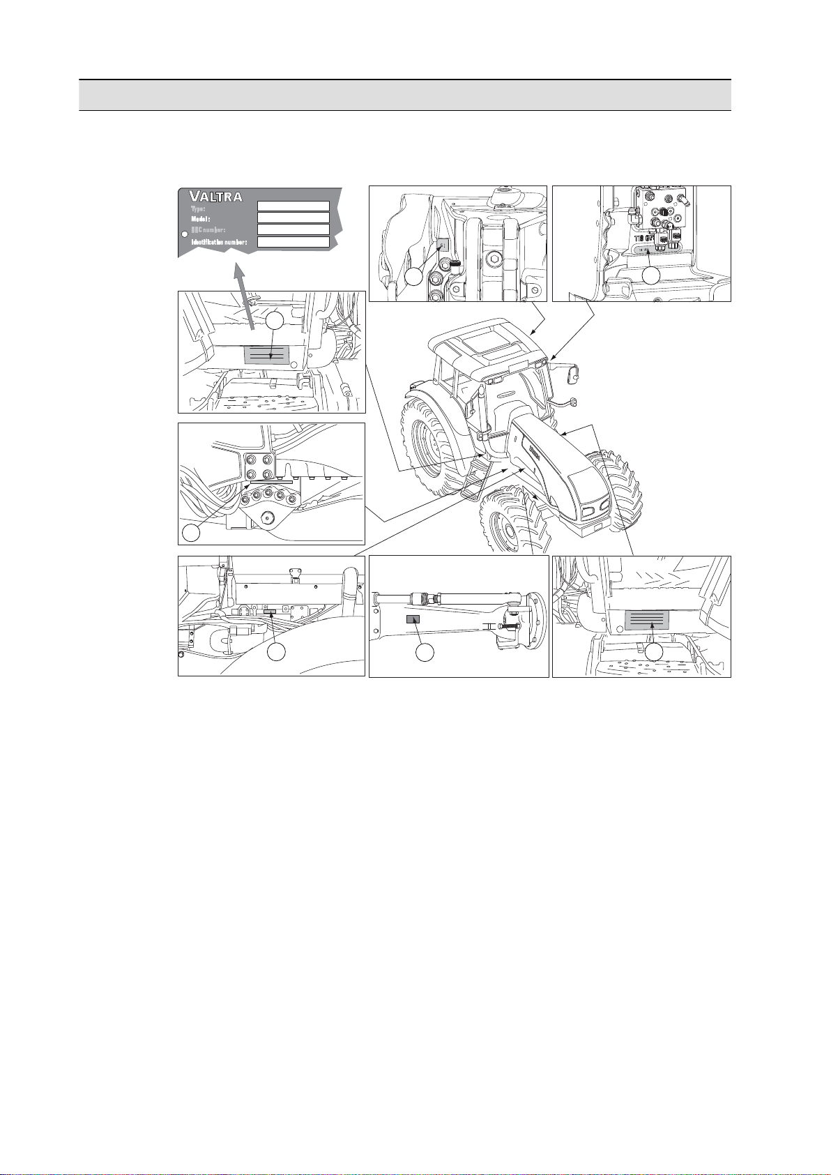
Tractor serial numbers
3
T133 H ACxx.x
5
6
xxxxx
7
2
1
4
When ordering spare parts or service, give the model indication and serial
numbers and, in some cases, the engine, front axle, cab and transmission numbers.
GUID-91B52FC7-EDE8-4BB8-9403-DE0873CA0857
1. Power take-off identification number
2. Transmission Identification number
3. Type plate EEC
• Model = model indication used by service/spare part department
• Identification number = tractor serial number
4. Tractor serial number
5. Engine number
6. Front axle number
7. Cab number
- 2 -
Page 4

Contents
Contents
About this manual........................................................................................1
Tractor serial numbers.................................................................................2
1 Safety precautions................................................................................13
1.1 Hazard statements.............................................................................................13
1.2 Safety rules........................................................................................................13
1.2.1 Replacing safety and information signs............................................................13
1.2.2 Maintaining hardware safety............................................................................14
1.2.3 Using tractor safety features............................................................................15
1.2.4 Safe operation..................................................................................................16
1.2.4.1 Following safe operating practices.............................................16
1.2.4.2 Getting into and out of the cab....................................................18
1.2.4.3 Driving on public roads...............................................................18
1.2.4.4 Controlling the driving speed......................................................19
1.2.4.5 Driving downhill...........................................................................19
1.2.4.6 Operating with implements.........................................................20
1.2.4.7 Running with power take-off driven implements or
machines....................................................................................21
1.2.4.8 Using ballast weights..................................................................21
1.2.4.9 Towing........................................................................................22
1.2.4.10 Ensuring personal safety of other people...................................22
1.2.4.11 Fire hazards................................................................................23
1.2.4.12 Handling viton seals subjected to high temperatures.................23
1.2.4.13 After-treatment system...............................................................23
2 Instruments and controls......................................................................25
2.1 Pedals................................................................................................................25
2.2 Dashboard.........................................................................................................25
2.2.1 Agroline instrument panel.................................................................................26
2.2.1.1 Symbols on the Agroline instrument panel display.....................26
2.2.1.2 Indicator lights on the left side of the display..............................27
2.2.1.3 Indicator lights on the right side of the display............................28
2.3 Dashboard.........................................................................................................29
2.3.1 Proline instrument panel ..................................................................................29
2.3.1.1 Symbols on the Proline instrument panel display.......................30
2.3.1.2 Indicator lights on the left side of the display..............................31
2.3.1.3 Indicator lights on the right side of the display............................32
2.4 Controls on the right-hand side..........................................................................34
2.4.1 Driving controls.................................................................................................34
2.4.2 Linkage.............................................................................................................36
2.4.3 Power take-off..................................................................................................37
2.4.4 Auxiliary hydraulics...........................................................................................39
2.4.5 Other controls...................................................................................................40
2.5 Controls on the rear side....................................................................................41
2.5.1 Rear window opening device...........................................................................41
2.5.2 Reverse drive system controls.........................................................................42
2.6 Controls on the left-hand side............................................................................43
2.7 Controls on the front roof console .....................................................................44
2.8 Controls on the right-hand side roof console.....................................................45
2.9 Controls on the forest equipment right-hand side roof console.........................46
2.10 Controls on the left-hand side roof console.......................................................46
2.11 Controls on the forest equipment left-hand side roof console............................47
2.12 Air conditioning controls.....................................................................................47
2.12.1 Manual air conditioning controls ......................................................................47
2.12.2 Automatic air conditioning controls ..................................................................48
2.13 Driver's seat.......................................................................................................49
- 3 -
Page 5

Contents
2.14 Air suspended driver's seat ...............................................................................50
2.15 Controls on the rear mudguard..........................................................................51
2.16 Controls on the bonnet.......................................................................................51
2.17 Rear controls and connections outside the cab.................................................52
2.18 Engine hood locking...........................................................................................53
3 Operation..............................................................................................54
3.1 Running the tractor in.........................................................................................54
3.2 Preparing for use...............................................................................................54
3.2.1 Adjusting the driver's seat................................................................................54
3.2.2 Adjusting the air-suspended driver's seat........................................................56
3.2.3 Adjusting the armrest.......................................................................................59
3.2.4 Adjusting the steering wheel............................................................................60
3.2.5 Adjusting standard mirrors ..............................................................................61
3.2.6 Adjusting optional mirrors.................................................................................61
3.2.7 Heating mirrors.................................................................................................62
3.2.8 Using the windscreen wiper and washer..........................................................62
3.2.9 Using the rear window heater...........................................................................62
3.2.10 Using the rear window wiper............................................................................63
3.2.11 Using the rear window washer.........................................................................64
3.2.12 Power shuttle lever...........................................................................................64
3.2.13 Using the main switch......................................................................................65
3.2.14 Control stop......................................................................................................65
3.2.15 Using the control stop.......................................................................................66
3.2.16 Using the ignition switch...................................................................................66
3.2.17 Using the roof hatch.........................................................................................68
3.3 Starting the tractor.............................................................................................68
3.3.1 Starting under normal conditions......................................................................68
3.3.2 Starting under cold conditions..........................................................................70
3.3.3 Starting with an auxiliary battery......................................................................71
3.4 Using lights........................................................................................................71
3.4.1 Using headlights...............................................................................................71
3.4.2 Using upper headlights.....................................................................................72
3.4.3 Using working lights.........................................................................................72
3.4.4 Using the trailer hitch light................................................................................73
3.4.5 Using the cab light............................................................................................74
3.5 Using notification devices..................................................................................75
3.5.1 Using the direction indicators...........................................................................75
3.5.2 Using the horn..................................................................................................75
3.5.3 Using the rotating warning light........................................................................76
3.5.4 Using hazard warning flashers ........................................................................76
3.6 Heating and ventilation......................................................................................77
3.6.1 Using the heater...............................................................................................77
3.6.2 Controlling ventilation nozzles and air recirculation.........................................78
3.6.3 Using the manual air conditioning....................................................................79
3.6.4 Automatic air conditioning................................................................................80
3.6.4.1 Air conditioning control panel......................................................80
3.6.4.2 Activating air conditioning when the battery has been
disconnected...............................................................................81
3.6.4.3 Air conditioning control...............................................................81
3.6.4.4 Controlling the fan.......................................................................82
3.6.4.5 Automatic air conditioning system on/off button.........................83
3.6.4.6 Temperature view.......................................................................83
3.6.4.7 Temperature control...................................................................83
3.6.4.8 Defrosting...................................................................................84
3.6.4.9 Selecting air recirculation............................................................85
3.7 Power outlets.....................................................................................................86
3.7.1 Lighter..............................................................................................................86
3.7.2 Using the two-pin power socket and power switch...........................................86
3.7.3 Three-pin power socket....................................................................................87
- 4 -
Page 6

Contents
3.7.4 Trailer socket....................................................................................................88
3.7.5 Two-pin power socket on the bonnet...............................................................88
3.8 Driving the tractor...............................................................................................89
3.8.1 Steering............................................................................................................89
3.8.2 Power shuttle....................................................................................................89
3.8.3 Using the power shuttle lever...........................................................................90
3.8.4 Adjusting the power shuttle engagement speed .............................................91
3.8.5 Using the parking brake...................................................................................92
3.8.6 Using the clutch pedal......................................................................................94
3.8.7 Adjusting the clutch pedal engagement position..............................................94
3.8.8 Braking.............................................................................................................96
3.8.9 Using the emergency brake.............................................................................96
3.8.10 Starting to drive................................................................................................97
3.8.11 Transmission system........................................................................................98
3.8.11.1 Speed matching..........................................................................99
3.8.11.2 Selecting the range gear.............................................................99
3.8.11.3 Selecting the speed gear..........................................................100
3.8.11.4 Using Powershift.......................................................................100
3.8.11.5 Preprogramming gear for driving direction changing................101
3.8.11.6 Using the shifting automatics....................................................103
3.8.11.7 Programming shifting automatics.............................................104
3.8.12 Parking the tractor..........................................................................................105
3.8.13 Refueling the tractor.......................................................................................106
3.8.13.1 Filling the fuel tank....................................................................106
3.8.13.2 Filling the AdBlue/DEF tank......................................................107
3.8.14 Cruise control.................................................................................................108
3.8.14.1 Cruise control switches.............................................................108
3.8.14.2 Programming the driving speed cruise control.........................109
3.8.14.3 Activating and deactivating the driving speed cruise
control ......................................................................................109
3.8.14.4 Programming the engine speed cruise control.........................110
3.8.14.5 Activating and deactivating the engine speed cruise
control.......................................................................................111
3.8.14.6 Decreasing the cruise control setting........................................111
3.8.14.7 Increasing the cruise control setting.........................................112
3.8.15 Automatic traction control...............................................................................113
3.8.16 Using the automatic traction control...............................................................113
3.8.17 Front axle air suspension...............................................................................115
3.8.18 Disengaging the front axle air suspension.....................................................115
3.8.19 AutoComfort cab suspension.........................................................................116
3.8.19.1 Adjusting AutoComfort cab suspension....................................117
3.8.19.2 Calibrating AutoComfort cab suspension.................................118
3.8.19.3 Deactivating front axle suspension...........................................119
3.8.20 Differential lock...............................................................................................120
3.8.21 Engaging and disengaging the differential lock..............................................120
3.8.22 Four-wheel drive.............................................................................................121
3.8.23 Engaging and disengaging the four-wheel drive............................................122
3.8.24 Driving start automatics..................................................................................122
3.8.25 Setting the driving start automatics................................................................122
3.8.26 Reverse drive system.....................................................................................124
3.8.27 Permitted driving inclinations for driving the tractor on a slope......................125
3.9 Proline instrument panel display......................................................................125
3.9.1 Fixed views.....................................................................................................126
3.9.2 Selecting a view.............................................................................................126
3.9.3 Top and middle row views..............................................................................127
3.9.3.1 Working time view.....................................................................128
3.9.3.2 Cruise control view...................................................................128
3.9.3.3 Driving speed view....................................................................129
3.9.3.4 Wheel slip view.........................................................................129
3.9.3.5 Rear power take-off speed view...............................................129
- 5 -
Page 7

Contents
3.9.3.6 Front power take-off speed view...............................................130
3.9.3.7 Engine speed view....................................................................130
3.9.3.8 Fuel consumption views...........................................................130
3.9.3.9 Rear lower links' position view..................................................132
3.9.3.10 Front lower links' position view.................................................132
3.9.3.11 Sigma Power view....................................................................133
3.9.3.12 Gearbox temperature view.......................................................133
3.9.3.13 Travel distance view.................................................................134
3.9.3.14 Surface area view.....................................................................134
3.9.4 Periodical maintenance view..........................................................................135
3.9.4.1 Clearing the periodical maintenance view................................135
3.9.5 Resetting views..............................................................................................136
3.9.6 Enlarging the middle row................................................................................136
3.9.7 Changing parameters.....................................................................................137
3.9.7.1 Activating and exiting the setting mode....................................137
3.9.7.2 Changing the parameter value.................................................138
3.9.7.3 Setting the display backlight level.............................................138
3.9.7.4 Setting the implement width......................................................139
3.9.7.5 Changing the hour display........................................................139
3.9.7.6 Changing the minute display....................................................139
3.9.7.7 Changing the clock mode.........................................................140
3.9.7.8 Activating the direction indicator buzzer...................................140
3.9.7.9 Changing the temperature unit.................................................140
3.9.7.10 Changing the length unit...........................................................141
3.9.7.11 Changing the volume unit.........................................................141
3.9.7.12 Activating and deactivating the front power take-off speed
view...........................................................................................142
3.9.7.13 Activating and deactivating the front lower links' position
view...........................................................................................142
3.9.7.14 Adjusting the display contrast...................................................142
3.10 Agroline instrument panel display....................................................................143
3.10.1 Fixed views.....................................................................................................143
3.10.2 Selecting a view.............................................................................................144
3.10.3 Top and bottom row views.............................................................................144
3.10.3.1 Travel distance view.................................................................145
3.10.3.2 Rear power take-off speed view...............................................145
3.10.3.3 Front power take-off speed view...............................................145
3.10.3.4 Clock.........................................................................................146
3.10.3.5 Gearbox temperature view.......................................................146
3.10.3.6 Rear lower links' position view..................................................146
3.10.4 Periodical maintenance view..........................................................................147
3.10.4.1 Clearing the periodical maintenance view................................147
3.10.5 Resetting views..............................................................................................148
3.10.6 Changing parameters.....................................................................................149
3.10.6.1 Activating and exiting the setting mode....................................149
3.10.6.2 Setting the display backlight level.............................................149
3.10.6.3 Resetting time...........................................................................150
3.10.6.4 Changing the clock mode.........................................................150
3.10.6.5 Changing the Agroline tyre parameters for different tyres........151
3.11 A-pillar display..................................................................................................151
3.11.1 Power shuttle section.....................................................................................152
3.11.2 Transmission section......................................................................................153
3.11.3 General information section...........................................................................154
3.11.4 Changing general information section views..................................................155
3.12 Rear linkage.....................................................................................................156
3.12.1 Diagnose light.................................................................................................157
3.12.2 Activating the linkage.....................................................................................157
3.12.3 Using the lift/stop/lower switch.......................................................................158
3.12.4 Using the position control knob......................................................................158
3.12.5 Using the linkage floating position..................................................................159
- 6 -
Page 8

Contents
3.12.6 Using the lift/lower switch and lift/lower push buttons....................................160
3.12.7 Lift/lower indicator lights ................................................................................161
3.12.8 Setting the lowering speed.............................................................................161
3.12.9 Limiting the lifting height.................................................................................162
3.12.10 Draft control....................................................................................................162
3.12.11 Activating and deactivating the draft control...................................................163
3.12.12 Passing the position set by the position control knob....................................163
3.12.13 Passing the height set by the lifting height selector.......................................164
3.12.14 Using the drive balance control .....................................................................165
3.12.15 Slip control......................................................................................................166
3.12.16 Using the slip control......................................................................................167
3.13 Three-point linkage..........................................................................................168
3.13.1 Attaching implements.....................................................................................169
3.13.2 Using quick couplings for lower links .............................................................170
3.13.2.1 Setting the release cable for lower link quick couplings ..........171
3.13.3 Adjusting lifting links ......................................................................................173
3.13.4 Adjusting lower links.......................................................................................173
3.13.5 Adjusting check links......................................................................................174
3.13.5.1 Adjusting the check links' length...............................................174
3.13.5.2 Adjusting the check links' support.............................................174
3.13.6 Automatic check links ....................................................................................175
3.13.6.1 Adjusting thread-adjustable check links....................................175
3.13.6.2 Adjusting pin-adjustable check links.........................................177
3.13.6.3 Using the floating position of automatic check links.................177
3.14 Auxiliary hydraulics..........................................................................................178
3.14.1 Controlling the auxiliary hydraulics rear valves .............................................179
3.14.2 Setting valves for single-action or double-action............................................181
3.14.3 Using quick-action couplings .........................................................................181
3.14.4 Connecting an external hydraulic motor to the auxiliary hydraulics...............182
3.15 Using the front linkage.....................................................................................182
3.15.1 Setting front linkage lifting link positions.........................................................184
3.16 Using the Valtra front loader............................................................................185
3.16.1 Using the Valtra Quick front loader coupling plate.........................................187
3.16.2 Softdrive.........................................................................................................187
3.16.3 Locking the equipment...................................................................................188
3.16.4 Using the continuous floating position............................................................189
3.16.5 Using the floating position with joystick buttons.............................................190
3.16.6 Controlling the extra cylinder with the change valve......................................191
3.17 Power take-off..................................................................................................192
3.17.1 Attaching implements to the power take-off...................................................192
3.17.2 Rear power take-off........................................................................................194
3.17.2.1 Recommended rear power take-off shafts................................195
3.17.2.2 Activating rear power take-off...................................................196
3.17.2.3 Starting rear power take-off......................................................197
3.17.2.4 Stopping rear power take-off temporarily..................................198
3.17.2.5 Deactivating rear power take-off...............................................199
3.17.2.6 Stopping the rear power take-off in emergency........................200
3.17.2.7 Using the rear power take-off automatic stop...........................201
3.17.2.8 Proportional ground speed power take-off................................202
3.17.2.9 Adjusting the rear power take-off engagement.........................203
3.17.3 Front power take-off.......................................................................................205
3.17.3.1 Activating and deactivating front power take-off.......................206
3.18 Implement signal connection...........................................................................207
3.18.1 Resetting the implement signal connection....................................................208
3.19 Valtra ISOBUS.................................................................................................208
3.19.1 ISOBUS implement connector.......................................................................210
3.19.2 ISOBUS terminal connector...........................................................................210
3.19.3 Bus extension connectors..............................................................................211
3.19.4 Resetting the ISOBUS connection.................................................................212
- 7 -
Page 9

Contents
3.20 Towing devices................................................................................................212
3.20.1 Pick-up hitch...................................................................................................212
3.20.1.1 Unlatching the pick-up hitch equipped with mechanical
unlatching system ....................................................................212
3.20.1.2 Unlatching the pick-up hitch equipped with hydraulic
unlatching system.....................................................................213
3.20.1.3 Latching the pick-up hitch.........................................................215
3.20.2 Agricultural drawbar devices..........................................................................216
3.20.3 Towing device frames ...................................................................................217
3.20.3.1 Adjusting the jaw height............................................................218
3.20.3.2 Attaching to the mechanical jaw...............................................219
3.20.3.3 Attaching to the automatic jaw..................................................219
3.20.4 Euro pick-up hitch...........................................................................................221
3.20.5 Euro pick-up hitch with hydraulic extension...................................................223
3.20.5.1 Unlatching the hydraulically extended Euro pick-up hitch........223
3.20.5.2 Extending the Euro pick-up hitch..............................................224
3.20.5.3 Latching the hydraulically extended Euro pick-up hitch............225
3.20.5.4 Changing the pick-up hitch or drawbar.....................................227
3.21 Air pressure system.........................................................................................229
3.22 Trailer...............................................................................................................231
3.22.1 Trailer air pressure brakes.............................................................................231
3.22.2 Trailer fluid brake valve..................................................................................232
4 Maintenance.......................................................................................234
4.1 Maintenance schedule.....................................................................................234
4.2 Service inspection............................................................................................234
4.3 Performing maintenance tasks........................................................................235
4.3.1 Cleaning the tractor........................................................................................236
4.3.1.1 Cleaning the engine compartment............................................237
4.3.1.2 Cleaning front axle suspension bellows....................................237
4.3.1.3 Cleaning polycarbonate windows.............................................237
4.3.2 Greasing lubricating points fitted with grease nipples....................................238
4.3.3 Supporting the tractor.....................................................................................238
4.4 Recommended fuel and lubricants..................................................................240
4.4.1 Fuel................................................................................................................240
4.4.1.1 Quality requirements for engine fuel.........................................240
4.4.1.2 Storing fuel................................................................................240
4.4.1.3 Storing AdBlue/DEF..................................................................240
4.4.1.4 Biodiesel fuel............................................................................241
4.4.2 Grease............................................................................................................241
4.4.2.1 Universal Grease - NLGI2 universal grease.............................241
4.4.2.2 Calsium LF - NLGI2 calsium grease LF....................................242
4.4.2.3 Grease Moly - NLGI2 moly grease...........................................242
4.5 Storing the tractor............................................................................................242
4.5.1 Storing the tractor for a period shorter than two months................................242
4.5.2 Storing the tractor for a period longer than two months.................................243
4.6 Running the tractor in after storage.................................................................243
4.6.1 Running the tractor in after a storing period shorter than two months...........243
4.6.2 Running the tractor in after a storing period longer than two months............244
4.7 Periodical maintenance....................................................................................244
4.7.1 Periodical maintenance chart.........................................................................245
4.7.2 Daily maintenance..........................................................................................247
4.7.2.1 Checking the engine oil level....................................................247
4.7.2.2 Checking the oil level in the transmission system....................248
4.7.2.3 Checking the coolant level........................................................249
4.7.2.4 Cleaning radiators.....................................................................250
4.7.2.5 Checking the AdBlue/DEF tank level........................................251
4.7.3 Weekly maintenance......................................................................................252
4.7.3.1 Greasing the three-point linkage...............................................252
4.7.3.2 Checking the pick-up hitch........................................................252
- 8 -
Page 10

Contents
4.7.3.3 Greasing the pick-up hitch........................................................253
4.7.3.4 Maintaining the front linkage.....................................................253
4.7.3.5 Checking the front power take-off.............................................254
4.7.3.6 Greasing the brake cam...........................................................255
4.7.3.7 Greasing front axle mounting bearings.....................................255
4.7.3.8 Greasing air-suspended front axle mounting bearings.............256
4.7.3.9 Greasing flexible front mudguards............................................257
4.7.3.10 Checking belts' tension.............................................................257
4.7.3.11 Changing the fan and air pressure compressor belt.................258
4.7.3.12 Changing the alternator and air conditioning compressor
belt............................................................................................260
4.7.3.13 Checking the fuel system prefilter and sediment bowl..............261
4.7.3.14 Checking the electrolyte level in the battery.............................262
4.7.3.15 Checking the tyre pressure.......................................................263
4.7.3.16 Checking wheel nuts' tightness................................................263
4.7.3.17 Checking the emergency brake................................................263
4.7.3.18 Windscreen washer fluid reservoir............................................264
4.7.4 Maintenance every 500 hours........................................................................264
4.7.4.1 Greasing door hinges...............................................................264
4.7.4.2 Changing the engine oil and the oil filter...................................264
4.7.4.3 Checking the engine breathing system.....................................266
4.7.4.4 Cleaning the cab ventilation air filter.........................................266
4.7.4.5 Checking the brake pedal free travel........................................267
4.7.4.6 Adjusting brake pedals' travel...................................................268
4.7.4.7 Checking the parking brake......................................................269
4.7.4.8 Adjusting the parking brake......................................................269
4.7.4.9 Changing transmission oil filters...............................................271
4.7.4.10 Changing hydraulic system oil filters........................................272
4.7.4.11 Checking the oil level in the front axle differential.....................273
4.7.4.12 Checking the oil level in front axle hubs...................................274
4.7.4.13 Changing front PTO housing oil and washing oil filter..............275
4.7.4.14 Checking front PTO rubber couplings.......................................276
4.7.4.15 Checking and greasing the trailer air-pressure brake
system......................................................................................276
4.7.4.16 Checking the air pressure system's automatic water
draining.....................................................................................276
4.7.4.17 Adjusting engine valves............................................................277
4.7.5 Maintenance every 1000 hours or yearly.......................................................277
4.7.5.1 Changing oil in the hydraulic system........................................277
4.7.5.2 Changing oil in the front axle differential...................................279
4.7.5.3 Changing oil in the front axle hubs...........................................280
4.7.5.4 Changing the cab ventilation air filter........................................281
4.7.5.5 Changing the recirculation filter................................................282
4.7.5.6 Changing the fuel filter..............................................................282
4.7.5.7 Changing the fuel prefilter.........................................................283
4.7.5.8 Changing engine air filters........................................................285
4.7.5.9 Changing the selective catalytic reduction system supply
module main filter.....................................................................287
4.7.5.10 Greasing the flywheel ring gear................................................289
4.7.5.11 Checking the front wheel toe-in................................................289
4.7.5.12 Adjusting toe-in of front wheels.................................................290
4.7.5.13 Changing the hydraulics breather.............................................290
4.7.5.14 Checking the power shuttle operation......................................291
4.7.5.15 Tightening frame nuts and bolts...............................................291
4.7.6 Maintenance every 2000 hours or every other year.......................................291
4.7.6.1 Changing oil in the transmission system..................................291
4.7.6.2 Cleaning the suction strainer....................................................293
4.7.6.3 Changing the transmission breather.........................................293
4.7.6.4 Changing oil in brake system....................................................294
4.7.6.5 Bleeding the brake system.......................................................295
4.7.6.6 Changing oil in the front axle brake system..............................296
- 9 -
Page 11

Contents
4.7.6.7 Cleaning the cooling system.....................................................297
4.7.6.8 Checking the engine vibration damper.....................................300
4.7.6.9 Maintaining the air conditioning................................................300
4.8 Checks and adjustments..................................................................................301
4.8.1 Changing tyres...............................................................................................301
4.8.1.1 Setting the tyre parameter........................................................302
4.8.1.2 Tyre parameters.......................................................................304
4.8.2 Track widths...................................................................................................308
4.8.2.1 Agricultural front axle track widths............................................308
4.8.2.2 Industrial front axle track widths...............................................309
4.8.2.3 Rear axle track widths..............................................................310
4.8.3 Using chains...................................................................................................310
4.8.4 Using twin-mounted wheels...........................................................................311
4.8.5 Engine............................................................................................................311
4.8.5.1 Bleeding the fuel system...........................................................311
4.8.6 Electrical system............................................................................................312
4.8.6.1 Safety precautions for the electrical system.............................312
4.8.6.2 Checking the battery.................................................................312
4.8.6.3 Alternator..................................................................................313
4.8.6.4 Protecting the electrical system before welding........................313
4.8.6.5 Fuses and relays......................................................................313
4.8.6.6 Fuses and relays in the electric centre.....................................314
4.8.6.7 Fuses and relays for the urea component................................316
4.8.6.8 Engine induction air preheater fuse..........................................317
4.8.6.9 Cab power supply fuse.............................................................317
4.8.6.10 Adjusting headlights..................................................................318
4.8.7 Power transmission system............................................................................319
4.8.7.1 Changing the rear power take-off shaft....................................319
4.8.7.2 Checking the transmission ratio of a power take-off driven
trailer.........................................................................................319
4.8.8 Steering system..............................................................................................320
4.8.8.1 Adjusting the steering angle.....................................................320
4.8.9 Cab and shields..............................................................................................321
4.8.9.1 Adjusting the steps for driving off-road.....................................321
4.8.9.2 Limiting the door opening.........................................................322
4.8.9.3 Checking and adjusting front mudguards.................................322
4.8.9.4 Adjusting flexible front mudguards............................................323
4.8.10 Hydraulic system............................................................................................324
4.8.10.1 Adjusting lifting links of the pick-up hitch..................................324
4.8.10.2 Maintaining the automatic jaw of the wagon towing device......325
5 Faults and remedial actions...............................................................326
5.1 Handling error situations..................................................................................326
5.2 Errors indicated by the indicator lights.............................................................326
5.2.1 Cleaning the main engine air filter..................................................................327
5.2.2 Identifying a blocked transmission or hydraulic system filter..........................328
5.3 Warning symbols on the Proline instrument panel display..............................330
5.3.1 Low fuel pressure warning.............................................................................330
5.3.2 Transmission speed warning..........................................................................330
5.3.3 Power take-off speed warning........................................................................331
5.3.4 Fuel level sensor open circuit warning...........................................................331
5.3.5 Fuel level sensor short circuit warning...........................................................332
5.4 Viewing service codes.....................................................................................332
5.5 Service codes..................................................................................................333
5.6 Steering system malfunctions..........................................................................340
5.7 Towing the tractor............................................................................................340
5.7.1 Towing the tractor when the engine is running..............................................340
5.7.2 Towing the tractor when the engine is not running........................................341
6 Technical specifications.....................................................................342
- 10 -
Page 12

Contents
6.1 Dimensions......................................................................................................342
6.2 Weights............................................................................................................342
6.3 Maximum permissible axle loading..................................................................342
6.4 Tyres................................................................................................................343
6.4.1 Wheel nuts tightening torque..........................................................................344
6.4.2 Wheel stud dimensions..................................................................................344
6.4.3 Front axle tyre loadings and pressures..........................................................344
6.4.4 Rear axle tyre loadings and pressures...........................................................345
6.5 Spacing for wheel discs...................................................................................346
6.6 Track widths.....................................................................................................346
6.6.1 Rear track widths............................................................................................346
6.6.2 Front track widths...........................................................................................346
6.7 Engine..............................................................................................................347
6.7.1 Engine lubrication system..............................................................................348
6.7.2 Fuel system....................................................................................................348
6.7.3 Selective catalytic reduction system...............................................................349
6.7.4 Air cleaner......................................................................................................349
6.7.5 Cooling system...............................................................................................349
6.8 Electrical system..............................................................................................349
6.9 Power transmission..........................................................................................350
6.9.1 Power shuttle..................................................................................................350
6.9.2 Clutch.............................................................................................................350
6.9.3 Gearbox..........................................................................................................350
6.9.4 Rear axle differential lock...............................................................................350
6.9.5 Rear power take-off........................................................................................351
6.9.5.1 Rear power take-off alternatives...............................................351
6.9.5.2 Rear power take-off ratios........................................................351
6.9.5.3 Rear power take-off shafts........................................................351
6.9.5.4 Lower link end distance from rear power take-off shaft............351
6.9.5.5 Proportional ground speed.......................................................352
6.9.6 Front power take-off.......................................................................................352
6.9.6.1 Front power take-off ratios........................................................352
6.9.6.2 Front power take-off shafts.......................................................352
6.10 Brake system...................................................................................................352
6.11 Steering system...............................................................................................353
6.11.1 Front axle.......................................................................................................353
6.11.2 Turning circle radius.......................................................................................354
6.11.3 Front air suspension.......................................................................................354
6.12 Cab and shields...............................................................................................355
6.12.1 Cab filter capacity...........................................................................................355
6.12.2 Windscreen washer........................................................................................355
6.12.3 Air conditioning system..................................................................................355
6.12.4 Noise level......................................................................................................355
6.12.5 Exposure to vibration......................................................................................355
6.13 Hydraulic system..............................................................................................355
6.13.1 Low pressure circuit.......................................................................................355
6.13.2 Working hydraulic circuit................................................................................356
6.13.2.1 Valves for auxiliary hydraulics..................................................356
6.13.2.2 Counter pressure when using the return connection for
auxiliary hydraulics...................................................................356
6.13.3 Rear linkage...................................................................................................357
6.13.3.1 Maximum lifting force on the whole lifting area.........................357
6.13.3.2 Lifting range at the end of the lower links.................................357
6.13.4 Front linkage...................................................................................................358
6.13.5 Towing devices...............................................................................................358
6.13.5.1 Pick-up hitch.............................................................................358
6.13.5.2 Agricultural towing device.........................................................358
6.13.5.3 Towing device frames...............................................................359
6.13.5.4 Euro trailer hitch........................................................................360
- 11 -
Page 13

Contents
6.13.5.5 Euro trailer hitch with hydraulic extension................................360
6.13.5.6 Drawbar eye.............................................................................361
Alphabetical index...................................................................................362
- 12 -
Page 14

1 Safety precautions
Always follow the safety precautions given when working with the tractor.
The regulations given do not release the operator from statutory and other
national regulations as regards traffic safety and occupational health and safety.
In addition to the precautions given in this manual, always follow the safety
regulations applicable to different types of working sites and existing road traffic
laws.
1.1 Hazard statements
Five symbols are used in the documentation.
DANGER: Indicates an imminently hazardous situation that, if not
avoided, results in death or very serious injury.
WARNING: Indicates a potentially hazardous situation that, if not
avoided, could result in death or serious injury.
1. Safety precautions
CAUTION: Indicates a potentially hazardous situation that, if not
avoided, may result in minor injury.
IMPORTANT: Indicates special instructions or procedures which, if not strictly
observed, could result in damage to, or destruction of the machine, process or its
surroundings.
NOTE: Indicates points of particular interest for more efficient and convenient
repair or operation.
1.2 Safety rules
1.2.1 Replacing safety and information signs
Replacement signs are available from your dealer in the event of loss or damage.
• Replace any danger, warning, caution or instruction signs that are not
readable or are missing.
WARNING: Do not remove or obscure danger, warning, caution or
instruction signs.
- 13 -
Page 15

1. Safety precautions
1.2.2 Maintaining hardware safety
To ensure maximum safety for the operator, maintain tractor hardware safety.
The owner is responsible for repairing any damage or wear which might
endanger the safety of the tractor.
• Cab
Damages on the cab must be repaired without delay to ensure the cab's
protective capability.
WARNING: If damage occurs to the cab, replace all parts affected
with new ones. Do not attempt any repair work (welding, drilling,
cutting, or grinding) without first consulting the manufacturer.
• Tractor construction
Do not change the tractor construction, such as maximum driving speed or
maximum power.
The tractor is type approved to comply with construction and use regulations.
Any changes to the tractor construction may reduce safety and durability and
affect the warranty terms.
• Brakes
• Always check that the brakes are working before driving.
• Lock the brake pedals together whenever individual wheel brakes are not
required and always when driving on the road.
• Extensive repairs to the braking system should be undertaken only by an
authorised Valtra workshop.
• When implements or ballast weights are front-end mounted, the rear axle
loading is decreased:
• Check that the rear brakes are still effective.
• Use appropriate ballast weights at rear as required.
• Cleaning
Keep the tractor clean to minimise risk of fire.
• Lights
• Make sure that lights and reflectors are clean and in working order.
• Make sure that the headlights are correctly adjusted.
• Steps
Keep the steps clean. Dirty steps can lead to falls and personal injury.
• Quick couplings
DANGER: Clean the quick couplings and ball joints before
attaching an implement. There is risk that the implement is not
attached properly.
- 14 -
Page 16
• Maintenance
1
2
• Follow the maintenance instructions and safety precautions applicable to
the tractor.
• Stop the engine and lower the implement before carrying out any
maintenance work on the tractor or implement.
• Support the tractor from the correct support points on the frame and use
suitable blocks or stands when carrying out maintenance tasks that
require supporting the tractor.
1.2.3 Using tractor safety features
The tractor has several features that contribute to the operator's safety.
• Steering wheel and safety handles
WARNING: Hold on to the steering wheel or safety handles in the
cab if the tractor tips over. Never try to jump out.
• Safety belt
Always use the safety belt when using the tractor.
1. Safety precautions
• Emergency exits
Familiarise yourself with the four emergency exits of the tractor cab, that is,
the doors, the rear window and the roof hatch (extra equipment).
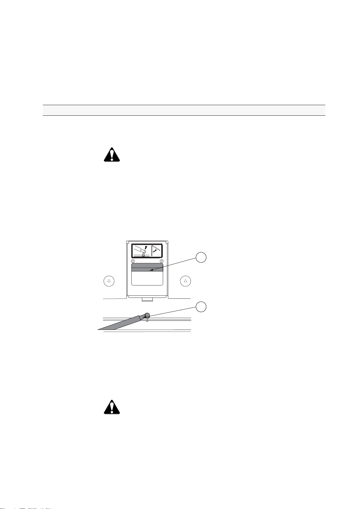
• Roof hatch (extra equipment)
GUID-E522C473-E223-48DF-BC14-03DCD1490CD2
1. Handle
2. Gas spring
• Open the hatch by pushing the handle forward and pushing the hatch
upward.
• To open the hatch fully (for emergency exit), detach the upper end of the
gas spring from its fastener and push the hatch fully open.
WARNING: When driving on ice, keep the roof hatch open.
- 15 -
Page 17
1
1. Safety precautions
1.2.4 Safe operation
1.2.4.1 Following safe operating practices
To operate the tractor safely, follow all the safety precautions and instructions.
• Avoid operating the tractor near ditches, embankments and holes.
• Stay off slopes too steep for safe operation.
• When using chemicals, carefully follow the chemical manufacturer’s
instructions for use, storage and disposal.
Also follow the chemical application equipment manufacturer’s instructions.
• Protect yourself against motor noise.
Use hearing protectors to avoid noise injuries when you are working outside
the cab near the engine.
• Avoid carbon monoxide poisoning.
WARNING: To avoid carbon monoxide poisoning, do not start the
engine or run it indoors with the doors closed unless the exhaust is
vented to the outside.
• Restarting after engine stop
• If the engine has stalled, for example due to too heavy loading, turn the
ignition key to the STOP position.
• Restart the engine.
Keep an eye on the indicator lights on the instrument panel.
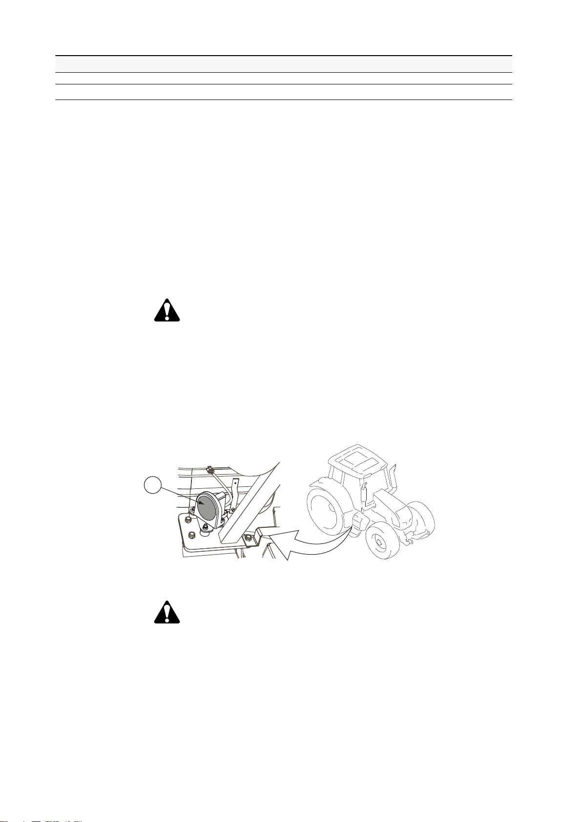
• Do not go under the tractor.
GUID-0BB05D71-A8AC-403B-B342-FCAD981AF07C
1. Radar
WARNING: Do not go under the tractor until the ignition key has
been turned to the STOP position. The tractor is equipped with
radar which presents a hazard to your eyes.
- 16 -
Page 18

1. Safety precautions
• Front loader
WARNING: The programmable features of the joystick or other
controls MUST NOT be used to operate a loader. In order to
prevent involuntary loader motion, the loader joystick controller
must be of a self-neutralising type. When the operator releases his
grip on the joystick, the joystick must return to a non-operational
neutral position - except for float detent position in the loader lower
direction.
• Ensure that no one is in the working area when you are working with a
front loader.
• Lower the front loader to the down position before leaving the tractor.
• Observe any special instructions issued by the loader manufacturer.
WARNING: The risk of overturn increases as the loader is raised.
Be extra careful on slopes when operating the loader. Always
carry the loader as low as practical for the conditions.
WARNING: Always look at the implement. Objects can fall or roll
backwards onto the driver when the loader is raised. Only lift loads
which can be contained in, and are intended for, the specific
implement.
• Differential lock
Use the differential lock only when running on loose or slippery ground.
• Overturning
• Always consider the way in which the tractor is to be used and the fact
that the centre of gravity of the tractor/implement assembly changes
according to the load being transported or towed.
• Adapt the tractor speed according to visibility, weather conditions and the
type of terrain.
WARNING: The instructions concerning overturning in this manual
are not exhaustive.
• Hydraulic/fuel pressure
Do not attempt to locate a leak in the hydraulic system or attempt to close a
leak using any part of your body.
CAUTION: Oil/fuel under high pressure easily penetrates through
clothing and skin and can cause serious injury.
• Hot surfaces
CAUTION: Be careful of hot surfaces during operation and service
work, in particular the engine and hydraulics components.
• Falling Object Protection Structure (FOPS)
DANGER: The cab structure is designed for protection against
falling objects (FOPS) in accordance with OECD-code 10 (energy
level 1362 J). Before operating, make sure the protection is
adequate for your work conditions.
- 17 -
Page 19

1. Safety precautions
• Operator Protection Structure (OPS)
• Hazardous substances EN 15695-1:2009
DANGER: Protection against penetrating objects is not provided
(no OPS available) if the cab of your tractor is fitted with windows
made of glass. Protection against penetrating objects is provided
in accordance with ISO 8084 (OPS is available) if the cab of your
tractor is fitted with windows made of polycarbonate, except the
Side visibility cab (no OPS in Side visibility cab). Before operating,
make sure the protection is adequate for your work conditions.
DANGER: The cab is classified as category 2 according to the
draft of EN15695-1:2009. Protection against dust is provided.
Protection against hazardous substances (agricultural chemicals,
etc.) is not provided. Personal protective equipment must be used
according to the chemical manufacturer's recommendations.
Without air conditioning and with manual air conditioning the fan
knob position must be 3 or higher and recirculation must be
closed. With automatic air conditioning the fan speed must be set
to maximum.
• Forest work
• When working in forest, pay special attention to safety issues. The
specific dangers related to forest work are overturning, falling objects and
penetrating objects.
1.2.4.2 Getting into and out of the cab
When getting into and out of the cab, pay special attention to safety issues.
• Always use three-point contact with the tractor and face the tractor when
getting in and out.
• Use handrails, grab handles and steps when getting in and out.
• Do not use the control levers as a handhold.
• Do not step on pedals when getting in and out.
• Never attempt to get into or out from a moving tractor.
• Never jump off a tractor.
1.2.4.3 Driving on public roads
When driving the tractor on public roads, pay special attention to the safety issues.
• Before driving
• Check that the tractor is safe for driving on the road.
• Adjust the rear view mirrors to give the correct viewing angle.
• Lock the check links with pins when transporting implements using three-
point linkage.
- 18 -
Page 20

• When driving the tractor on public roads
1
WARNING: Do not transport anything on the auxiliary hydraulic
valves while driving on the road. The load, trailer link steering and
such have to be locked (for example mechanically).
• Use the slow moving vehicle emblem on the rear end of the tractor if
allowed by law.
GUID-1CEA41C8-DCE5-4D4C-ACAD-50A81837A945
1. Slow moving vehicle emblem
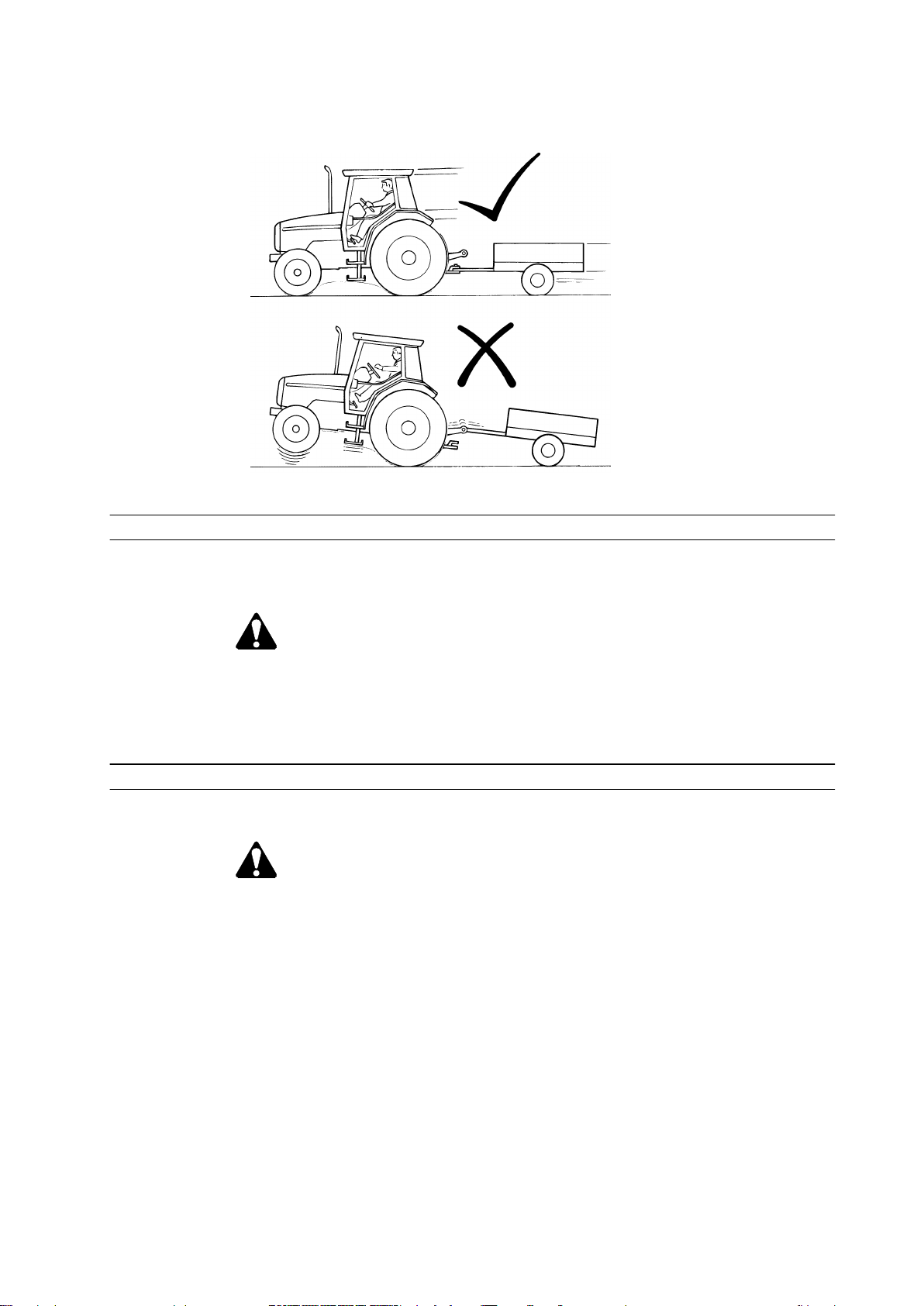
1.2.4.4 Controlling the driving speed
Adjust the driving speed to suit the driving surface, visibility and load.
1. Safety precautions
IMPORTANT: Do not alter the maximum driving speed of the tractor. The
maximum reverse driving speed is 20 km/h.
• Avoid any sudden increase or reduction (braking) in the driving speed.
• Avoid tight turns at high driving speed.
• When driving the tractor with an attached implement which centre of gravity
is far from the tractor, the tractor may sway considerably during cornering.
If care is not taken, the tractor may tip over or the load may be displaced.
1.2.4.5 Driving downhill
Be careful when driving downhill.
• Do not drive with the gear lever in neutral or the clutch pedal pressed down.
• Do not press the HiShift push button.
• Check the brakes often.
• Change to a lower gear before driving down a steep incline.
IMPORTANT: Do not brake continuously as the brakes may overheat.
IMPORTANT: Do not let the engine overrun to avoid damage to the engine.
NOTE: If the speed is too high, a speed warning is shown on the instrument
panel display and a buzzer goes off.
- 19 -
Page 21

1. Safety precautions
1.2.4.6 Operating with implements
Read and follow the instructions to avoid unnecessary risks when operating with
implements and attachments.
WARNING: Always follow carefully the instructions given in the
implement's user documentation. It is not allowed to use an implement
without reading and understanding all the precautions and regulations.
WARNING: Before entering between the tractor and the implement,
prevent the tractor from moving by applying the parking brake or
blocking the wheels. There is risk of accidents if the tractor or
implement should move.
WARNING: Implements attached to the linkage or the auxiliary
hydraulic system must be lowered to the ground while parking and
during maintenance.
WARNING: When installing an implement, air in hydraulic hoses and
cylinders can cause erratic operation.Run the engine at low speed and
make slow movements with the joystick to purge any air from the
hydraulic system.
WARNING: When installing an implement, keep hands and feet away
from moving components.Do not use your fingers to check the
alignment of holes or pins — use a mandrel or a steel rod.
WARNING: When disconnecting, the implement may fall downwards.
IMPORTANT: When attaching a trailer or implement, be sure not to exceed the
maximum weight of the rear axle. See the technical specifications in this manual
for the maximum permissible axle loading.
• Make sure to allow sufficient clearance for turning.
Three-point hitch and side-mounted implements make a much larger arc
when turning than towed equipment. Use only Valtra approved attachments
and implements.
• Familiarise yourself with the working area and terrain.
Pay attention to vertical clearance and limitations that arise due to the
increased reach.
- 20 -
Page 22
1. Safety precautions
• Pull only from the approved drawbar.
Towing or attaching to other locations may cause the tractor to overturn.
GUID-B824BDA5-67EA-4CC6-AB40-7D1D42AD9627
1.2.4.7 Running with power take-off driven implements or machines
Read and follow the given instructions to use power take-off (PTO) driven
implements and machines safely.
DANGER: Serious accidents may occur due to failure to use the
prescribed safety devices.
• Use the prescribed safety devices and ensure that they are in good condition.
• Follow the directions given by the implement or machine manufacturer.
1.2.4.8 Using ballast weights
Use ballast weights according to the instructions when needed.
WARNING: When driving on the road, at least 20% of the gross weight
of the tractor must be on the front axle. When lifting an implement, the
weight on the front end of the tractor is reduced, and the steering
ability of the tractor is impaired or sometimes lost.
IMPORTANT: When using salt liquid as ballast weight in the wheels, the
manufacturer does not take the responsibility for the damages caused by salt.
• Use sufficient ballast weights.
• Mount ballast weights only at the points intended for this purpose.
- 21 -
Page 23

1. Safety precautions
1.2.4.9 Towing
Read and follow the given instructions to tow a trailer or an implement safely.
WARNING: When the tractor is towing a trailer, the brake pedals must
be locked together. The brakes are not to be used individually for
steering.
WARNING: When using a trailer, make sure that the hitch latch is locked.
WARNING: When using a trailer, always use the trailer brakes if
required by law. The trailer brakes are recommended to be used in 50
km/h models also in those countries where it is not required by law.
WARNING: Be sure no one is standing between tractor and implement.
IMPORTANT: When attaching a trailer or implement, be sure not to exceed the
maximum weight of the rear axle. See the technical specifications in this manual
for the maximum permissible axle loading.
IMPORTANT: When attaching a trailer or implement, be sure not to exceed the
maximum load of the tyre type. See the technical specifications for maximum rear
axle tyre loadings.
• Couple a trailer to the drawbar using an approved trailer coupling.
• Always lower a loaded drawbar with the hydraulic lift.
• Check that trailer brakes are operating properly and observe any special
instructions issued by the trailer manufacturer.
• Secure the trailer load properly.
WARNING: On tractors with trailers, the load must be properly
secured. The load must not obstruct the operator’s vision, or cover
lights and reflectors. Loads which project more than 1 m behind
the vehicle train must be suitably marked. During daytime, this
should be done with a flag, and during darkness, with a red light
and a reflector arrangement.
1.2.4.10 Ensuring personal safety of other people
Avoid hazards for other people when using the tractor.
DANGER: Do not allow children in the cab or near the tractor or an
attached implement while the engine is running.
- 22 -
Page 24

1. Safety precautions
DANGER: If the tractor engine is running, do not leave anybody in the
cab without supervision, as the push buttons are easily operated.
Always apply the parking brake.
• Stop the engine and lower the implement to the ground when leaving the tractor.
• Do not let passengers ride in the tractor unless it is provided with a special
seat.
Other personal transport, for example on front-mounted loaders, is not
permissible.
• Do not let passengers ride on the platform inside the tractor.
• Never lend the tractor to a person who is not used to driving it.
DANGER: You may be held responsible for any resulting accidents.
• Do not allow children, untrained or unqualified persons to operate your tractor.
They could injure themselves or someone else.
1.2.4.11 Fire hazards
WARNING: Open fire, smoking and sparks are prohibited near the fuel
system and batteries. Especially when charging batteries, explosive
gases are present.
1.2.4.12 Handling viton seals subjected to high temperatures
At temperatures over 300°C, the viton seals of the engine produce highly
corrosive hydrofluoric acid.
• Do not touch viton seals subjected to abnormally high temperatures with your
bare hands.
Use neoprene rubber or heavy duty gloves and safety glasses when
decontaminating.
• Wash seals and the contaminated area with 10% calcium hydroxide or other
alkali solution.
• Put all the removed material in sealed plastic bags and deliver them to the
point stated by the authorities concerned.
WARNING: Never burn viton seals.
1.2.4.13 After-treatment system
The selective catalytic reduction (SCR) after-treatment system contains
vanadiumpentoxide. Vanadiumpentoxide can be hazardous to health.
The SCR after-treatment system is installed in the muffler, and is not hazardous
to health under normal use and handling.
- 23 -
Page 25

1. Safety precautions
When the SCR after-treatment system is handled in such a way that there is a
risk of exposure to dust, safety precautions must be taken. Such work includes,
for example, opening the after-treatment system, machining, and disposal of the
after-treatment system.
Safety instructions for work involving the SCR after-treatment system
• Inhalation: If dust is inhaled, the affected person must be immediately taken
to breathe plenty of fresh air. If a considerable amount of dust has been
inhaled, seek medical help.
• Contact with eyes: Rinse eyes immediately with water. If irritation continues,
seek medical help.
• Contact with skin: Wash with soap and water. Take off contaminated clothes.
• Swallowing: If a large amount has been swallowed, drink plenty of water and
try to vomit. Seek medical help.
Environmental hazards
Vanadiumpentoxide is toxic to aquatic organisms, and may cause long-term
adverse effects in the aquatic environment.
Precautions to protect the environment
All dust and spillage must be gathered in a container for recycling or disposal in
accordance with local regulations. They must not be allowed to enter water
systems or the general waste management system.
When an SCR after-treatment system is no longer used, it must be disposed of in
accordance with applicable EU regulations, national regulations, or local
regulations. EU classifies its parts as hazardous to the environment.
- 24 -
Page 26
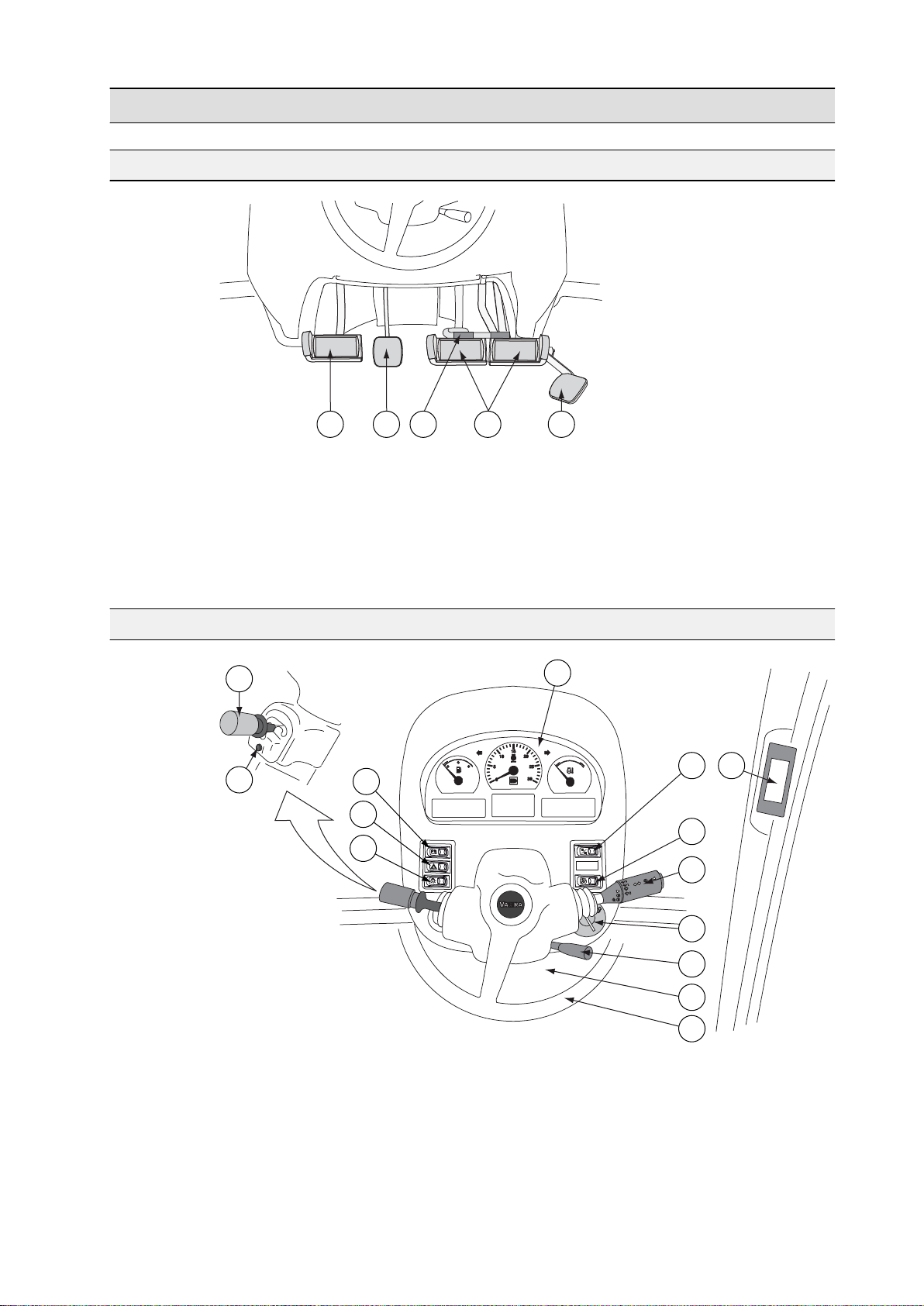
2 Instruments and controls
1 42
53
2
7
11
12
13
8
14
9
4
3
1
5
6
10
2.1 Pedals
GUID-B9DB5C5F-FE87-4414-8461-21CBE5754B55
1. Clutch pedal
2. Locking pedal for steering wheel inclination
3. Latch for brake pedals
4. Brake pedals
5. Accelerator pedal
2. Instruments and controls
2.2 Dashboard
GUID-55CC5AC8-1BDA-4194-9C71-7100EAC218AA
1. Power shuttle lever
2. Powershift preprogramming push button
3. Agroline instrument panel
4. Hazard warning flasher switch
5. Light switch
6. Agroline instrument panel display change-over switch
- 25 -
Page 27
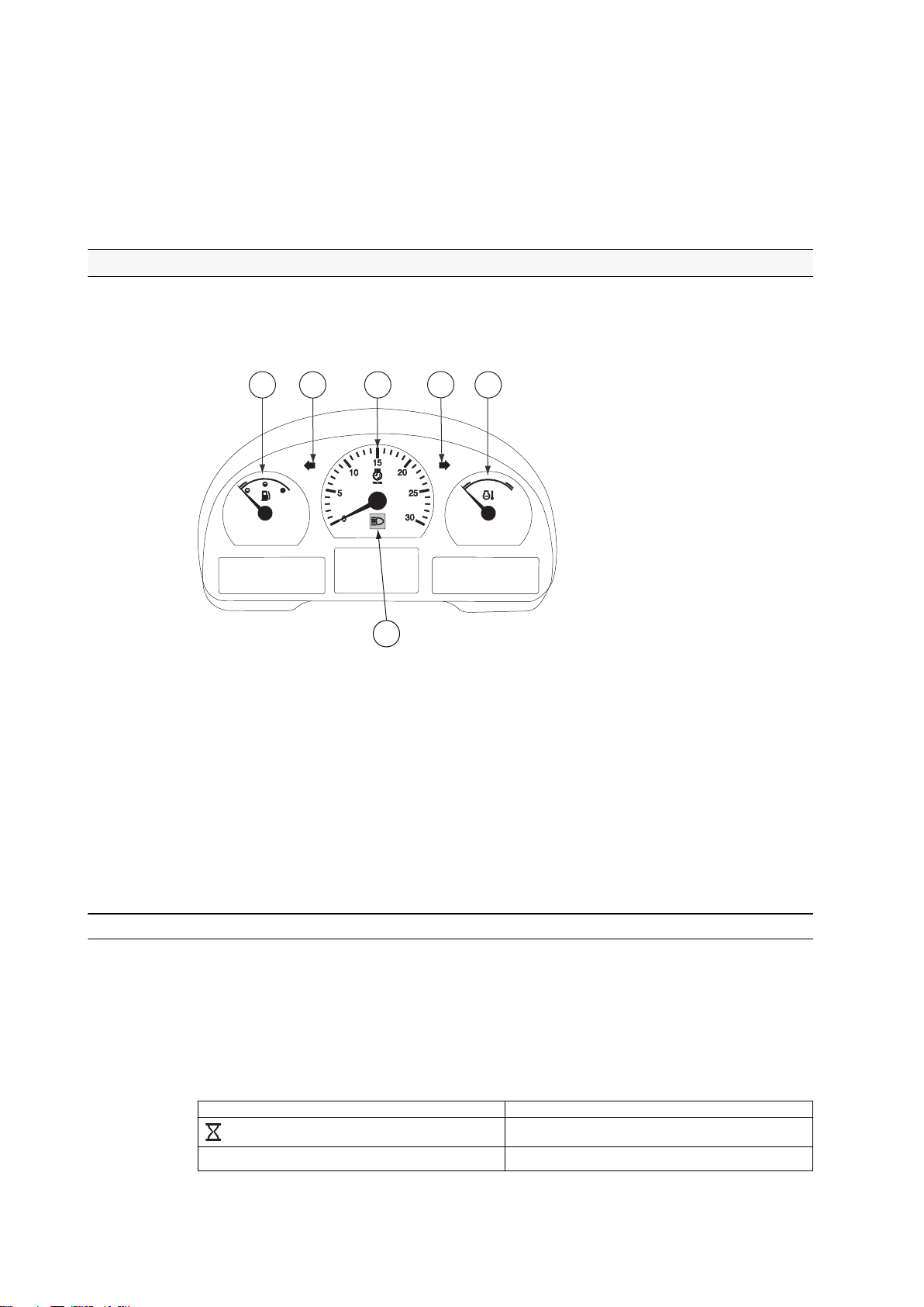
1
2 3
2
4
5
2. Instruments and controls
7. Upper headlights (extra equipment)
8. Multifunctional lever
9. Ignition switch
10. Lever for adjusting steering wheel position
11. Electric centre, lower part of the dashboard
12. Steering wheel
13. A-pillar display
2.2.1 Agroline instrument panel
The operator receives information from the gauges, coolant thermometer,
tachometer and indicator lights. All this can be seen on the Agroline instrument
panel.
GUID-C2C1308C-8200-47CD-A296-5FC6B94D7D73
1. Fuel gauge
2. Indicator lights for direction indicator
3. Tachometer
4. Coolant thermometer
5. Indicator light for the main beam
6. Agroline instrument panel display.
The fuel gauge shows the amount of fuel left in the tank.
The coolant thermometer indicates the engine temperature. The zone between
blue (cold) and red (hot) is the normal operating temperature.
2.2.1.1 Symbols on the Agroline instrument panel display
The Agroline instrument panel display has fixed views and views that can be
selected by the operator.
Fixed view symbols
The fixed views are the following two functions shown on the bottom row of the
display:
Symbol
km/h / mph Driving speed (km/h / miles/h)
Function
Operating hours (hhhh.h)
- 26 -
Page 28
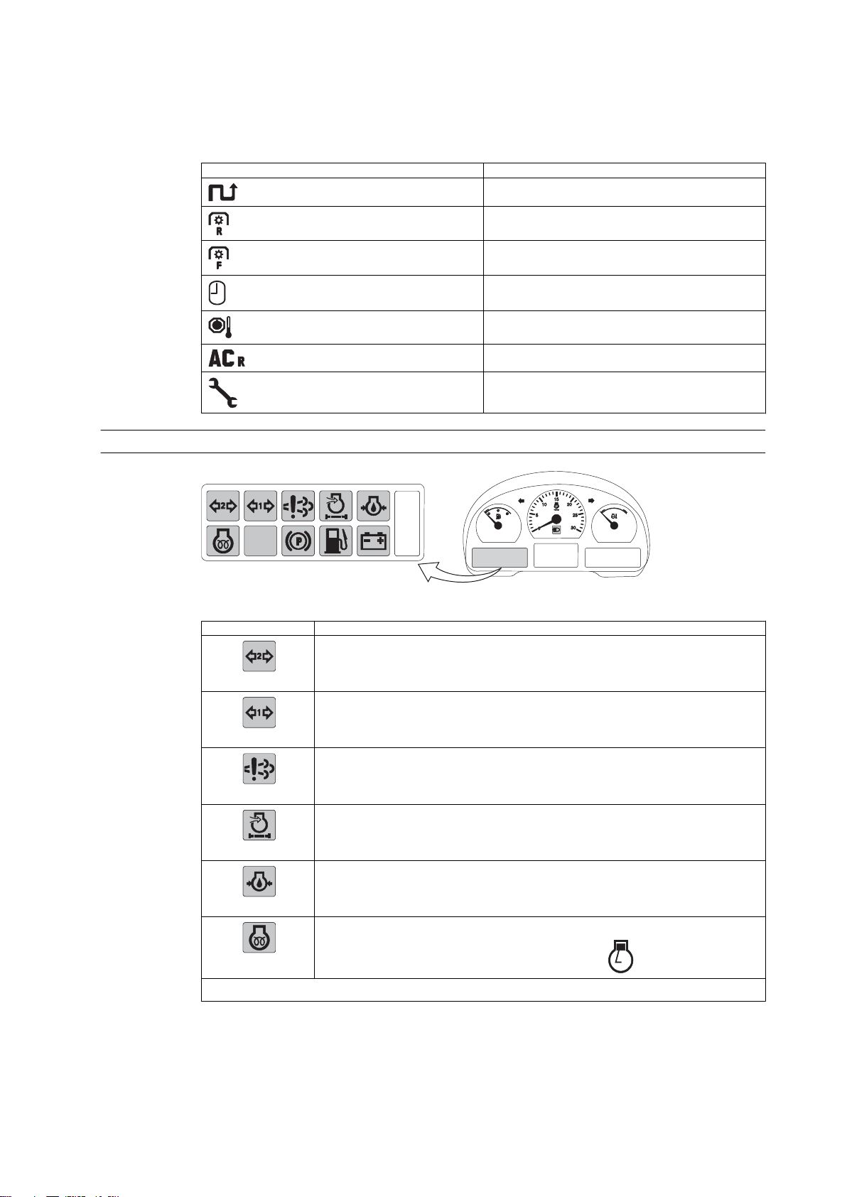
Selectable view symbols
The selectable views are the following functions shown on the top and bottom
row of the display:
Symbol Function
Driving trip (m, km/miles)
Rear PTO rotating speed (r/min)
Front PTO rotating speed (r/min, extra equipment)
Clock
Transmission temperature
Position of lower links (%, 0-100 Ac)
Maintenance schedule
2.2.1.2 Indicator lights on the left side of the display
2. Instruments and controls
GUID-947FA1AB-4198-42D2-8DE7-6B503089E7BE
Indicator light
Indication
Direction indicator light for second trailer (green)
GUID-32CAE5D4-C71C-4D8B-
A41F-2E1DE50F1ED4
If one of the bulbs on the combination has failed, this light is not lit.
Direction indicator light for first trailer (green)
GUID-16CF17A4-
D96E-4592-8DF3-1D4A100F090E
If one of the bulbs on the combination has failed, this light is not lit.
Engine emission system failure or malfunction indicator light
GUID-734ABCE0-5000-491A-9961-
AC15633FFC6C
Engine air cleaner clogging indicator light
GUID-06E4C986-88C7-44BA-9897-211
781955328
Engine oil pressure light
GUID-A1E9566C-86CE-4AD3-A512-
D772AE266E1E
Glow indicator light
GUID-9DD75249-0CC3-461D-84EC-
C9937C947DB9
The light (yellow) is lit when the ignition key is in position
Table continued on next page
and the engine is cold.
- 27 -
Page 29
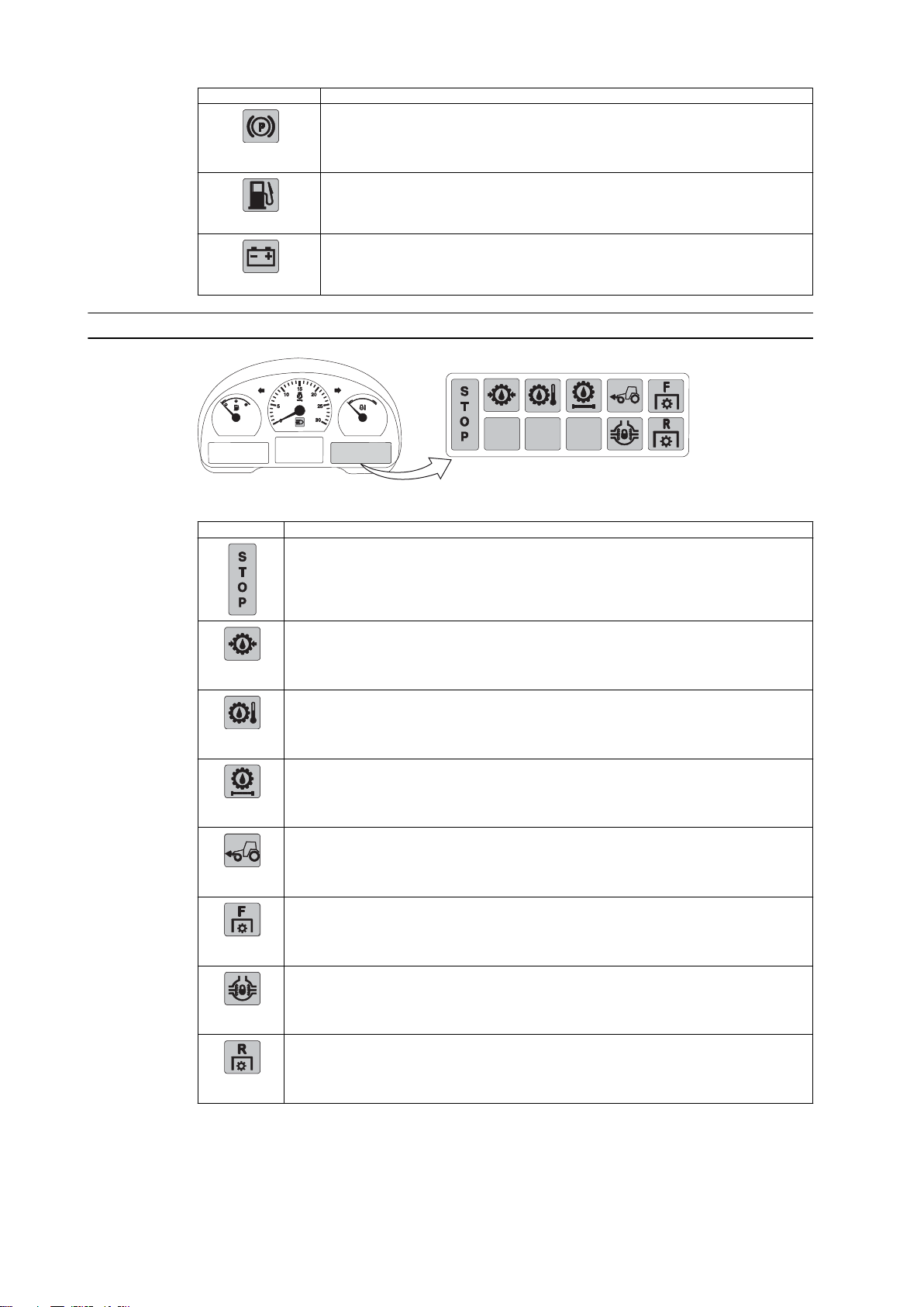
2. Instruments and controls
Indicator light Indication
Parking brake indicator light
GUID-
F0C90BFB-3126-404D-8C49-3FA955C
C4FD2
The light (red) is lit to indicate that the power shuttle lever is in the parking brake position.
Low fuel level indicator light
GUID-714DD8B7-ED71-4AA7-
BFAA-31C5E3693067
The light is lit (yellow) and a buzzer sounds once to indicate that about 50 litres of fuel
is left.
Battery charging indicator light
GUID-CD4C4C77-7CDB-4FB5-AF3A-
BEFDF3417EB1
2.2.1.3 Indicator lights on the right side of the display
GUID-57051FB5-C513-443B-A2FE-1E7ADF0A7DA9
Indicator light Indication
STOP indicator light (red)
Gearbox oil pressure light (red)
GUID-9B9A9C87-
BB4C-43A1-9A88-789929
9F22D0
Gearbox oil temperature light (red)
GUID-
AC890C72-21FE-4056-89
5A-DB34A4CE9357
Hydraulic pressure and auxiliary return oil filter clogging indicator light (red)
GUID-9B16B673-
D692-4975-
A9F9-5D6DBAFC4177
Front wheel drive indicator light
GUID-1E59203D-
F3B7-420D-ABC9-
F7433B7A6C19
The light is lit (yellow) to indicate that front wheel drive is engaged.
Front power take-off (PTO) indicator light
GUID-9AA1D60E-5812-4
B9F-
BDB0-44D48BEA8941
The light (yellow) is continuously on and indicates that the front PTO is engaged.
Differential lock indicator light
GUID-533CED2D-
D3E0-4488-8590-
A1E859BA91C5
The light is lit (yellow) to indicate that the differential lock is engaged.
Rear PTO indicator light
GUID-70C6E3BDC691-4819-BA77-
BA56A2A6A231
The light blinks (yellow) when the rear PTO has been activated and is ready to operate.The
light is on continuously when the rear PTO is engaged.
- 28 -
Page 30
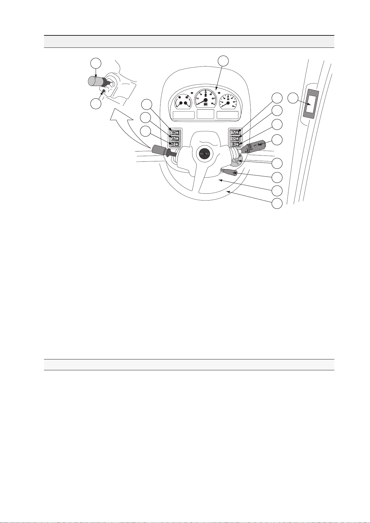
2.3 Dashboard
2
7
11
12
13
14
8
9
15
10
4
3
1
5
6
2. Instruments and controls
GUID-5F1247BB-4AFE-4B0B-8FFC-60D3175EC97E
1. Power shuttle lever
2. Powershift preprogramming push button
3. Proline instrument panel
4. Main switch
5. Hazard warning flasher switch
6. Light switch
7. Proline instrument panel display change-over switch
8. Proline instrument panel display setting switch
9. Upper headlights (extra equipment)
10. Multifunctional lever
11. Ignition switch
12. Lever for adjusting steering wheel position
13. Electric centre, lower part of the dashboard
14. Steering wheel
15. A-pillar display
2.3.1 Proline instrument panel
The operator receives information from the gauges, coolant thermometer,
tachometer, speedometer and indicator lights. All this can be seen on the Proline
instrument panel. The Proline instrument panel is an alternative equipment.
- 29 -
Page 31

1 2
4
5
3
3
6 7
cruise
cruise
RPM
RPM
cruise
cruise
KMH
KMH
2. Instruments and controls
GUID-FC2CD6B7-89CF-4206-B450-F2A852212AB7
1. Fuel gauge
2. Coolant thermometer
3. Indicator lights for direction indicator
4. Tachometer
5. Speedometer
6. Indicator light for the main beam
7. Proline instrument panel display
The fuel gauge shows the amount of fuel left in the tank.
The coolant thermometer indicates the engine temperature. The zone between
blue (cold) and red (hot) is the normal operating temperature.
2.3.1.1 Symbols on the Proline instrument panel display
The Proline instrument panel display has fixed views and views that can be
selected by the operator.
Fixed view symbols
The fixed views are the two functions shown on the bottom row of the display:
Symbol
Selectable view symbols
The selectable views are the functions shown on the top and centre row of the
display:
Symbol
Function
Operating hours (hhhh.h)
Clock (hh:mm)
Function
Working time (h:mm)
Cruise control
km/h/mph Driving speed (km/h/mph)
Wheel slip (%, 0-100)
Table continued on next page
- 30 -
Page 32
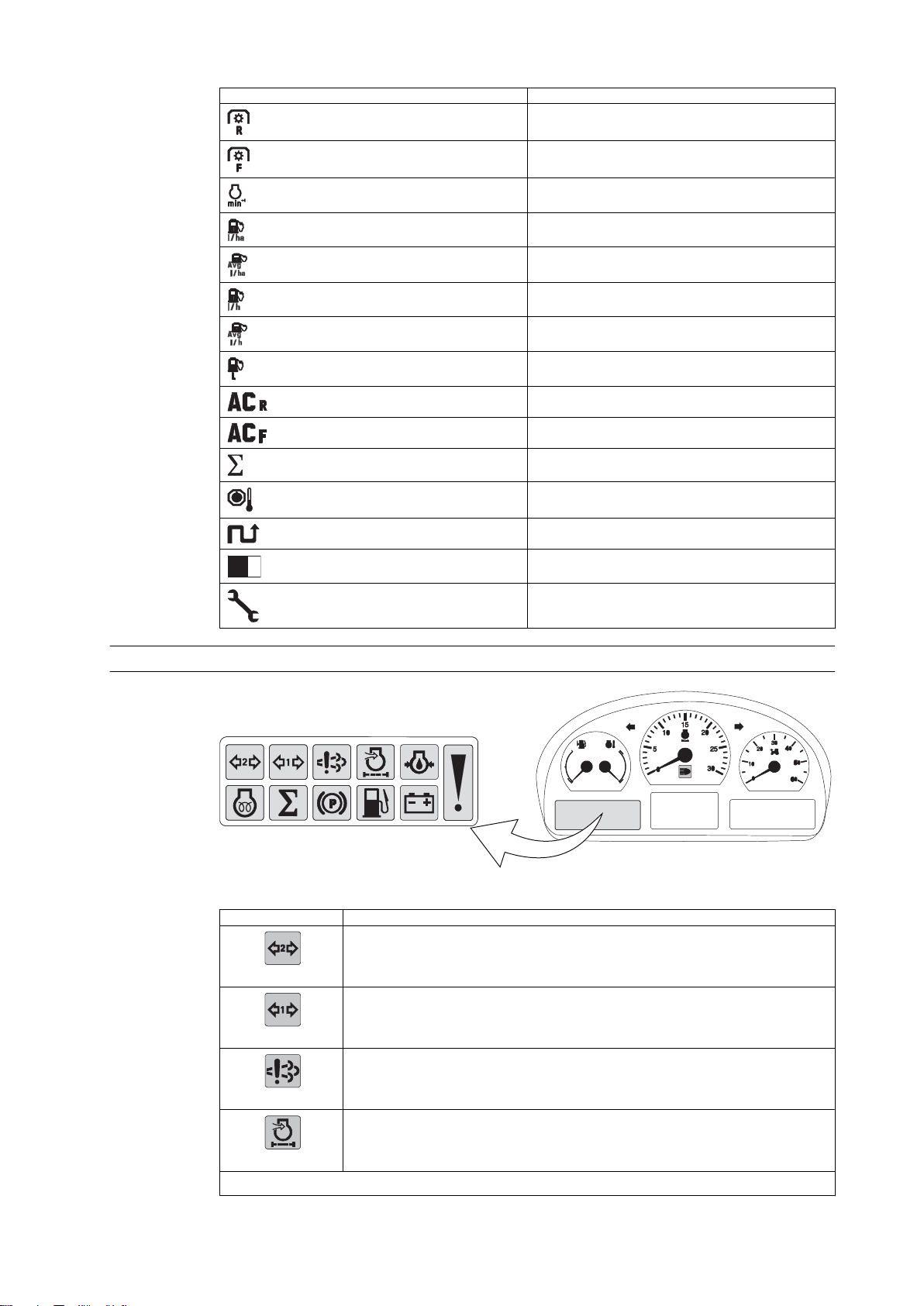
Symbol Function
Rear power take-off (PTO) speed (rpm)
Front power take-off (PTO) speed (rpm)
Engine speed (rpm)
Immediate fuel consumption (ha, acre)
Average fuel consumption (ha, acre)
Immediate fuel consumption
Average fuel consumption
Fuel consumption
Lower link position (%, 0-100)
Lifting link position of front linkage (%, 0-100)
Sigma power (%, 0–100)
2. Instruments and controls
Gearbox temperature (C/F)
Travel distance (m/km/miles)
Square area (ha)
Periodical maintenance
2.3.1.2 Indicator lights on the left side of the display
GUID-2E7BADD2-E500-4B99-84AB-7D46D7B01D69
Indicator light
GUID-32CAE5D4-C71C-4D8B-
A41F-2E1DE50F1ED4
GUID-16CF17A4-
D96E-4592-8DF3-1D4A100F090E
Indication
Direction indicator light for second trailer (green).
If one of the bulbs on the combination has failed, this light is not lit.
Direction indicator light for first trailer (green).
If one of the bulbs on the combination has failed, this light is not lit.
Engine emission system failure or malfunction indicator light.
GUID-734ABCE0-5000-491A-9961-
AC15633FFC6C
Engine air cleaner clogging indicator light.
GUID-06E4C986-88C7-44BA-9897-211
781955328
Table continued on next page
- 31 -
Page 33

CRUISE
F
R
S
T
O
P
2. Instruments and controls
Indicator light Indication
GUID-A1E9566C-86CE-4AD3-A512-
D772AE266E1E
GUID-8D5CD1CF-666F-46C9-9211-2B
B777A73D4E
GUID-9DD75249-0CC3-461D-84EC-
C9937C947DB9
GUID-
F0C90BFB-3126-404D-8C49-3FA955C
C4FD2
GUID-714DD8B7-ED71-4AA7-
BFAA-31C5E3693067
Engine oil pressure light
The exclamation mark is lit together with other indicator lights (yellow).
Glow indicator light
The light (yellow) is lit when the ignition key is in position
and the engine is cold.
Ʃ indicator light (on model T193 H)
The light is lit continuously (yellow) when the tractor is operating in the higher power
range and using PTO.
Parking brake indicator light
The light (red) is lit to indicate that the power shuttle lever is in the parking brake position.
Low fuel level indicator light
The light is lit (yellow) and a buzzer sounds once to indicate that about 50 litres of fuel
is left.
Battery charging indicator light
GUID-CD4C4C77-7CDB-4FB5-AF3A-
BEFDF3417EB1
2.3.1.3 Indicator lights on the right side of the display
GUID-0465EB98-1ABC-4D9F-99B4-4EE9E99E94E7
Indicator light
GUID-9B9A9C87-
BB4C-43A1-9A88-789929
9F22D0
Indication
STOP indicator light (red)
Gearbox oil pressure light
Gearbox oil temperature light
GUID-
AC890C72-21FE-4056-89
5A-DB34A4CE9357
Pressure oil filter clogging indicator light
GUID-9B16B673-
D692-4975-
A9F9-5D6DBAFC4177
Table continued on next page
- 32 -
Page 34

Indicator light Indication
Four-wheel drive (4WD) indicator light
GUID-1E59203D-
F3B7-420D-ABC9-
F7433B7A6C19
The light is lit (yellow) to indicate that 4WD is engaged.
Front power take-off (PTO) indicator light
GUID-9AA1D60E-5812-4
B9F-
BDB0-44D48BEA8941
The light (yellow) is continuously on and indicates that the front PTO (extra equipment) is
engaged.
Rear linkage indicator light
GUID-39523C54-
CBE4-40C9-98E5-3128D0
E9D502
The light is on (yellow) to indicate that the lift/stop/lower switch is in lift (transport) position.
Cruise control indicator light
GUID-4A174D51-0D8F-49
D5-A784-8C0B31037162
The light is on (yellow) to indicate that cruise control is engaged (constant driving speed/
constant engine speed chosen).
Creeper speed range indicator light
GUID-EA1BEE50-
CAFA-4268-8772-09CC8F
235C19
The light flashes (yellow) when the creeper gear is engaging.
Differential lock indicator light
GUID-533CED2DD3E0-4488-8590-
A1E859BA91C5
The light is lit (yellow) to indicate that the differential lock is engaged.
Rear PTO indicator light
GUID-70C6E3BDC691-4819-BA77-
BA56A2A6A231
The light blinks (yellow) when the rear PTO has been activated and is ready to operate. The
light is on continuously when the rear PTO is engaged.
2. Instruments and controls
- 33 -
Page 35

2. Instruments and controls
2.4 Controls on the right-hand side
2.4.1 Driving controls
- 34 -
Page 36
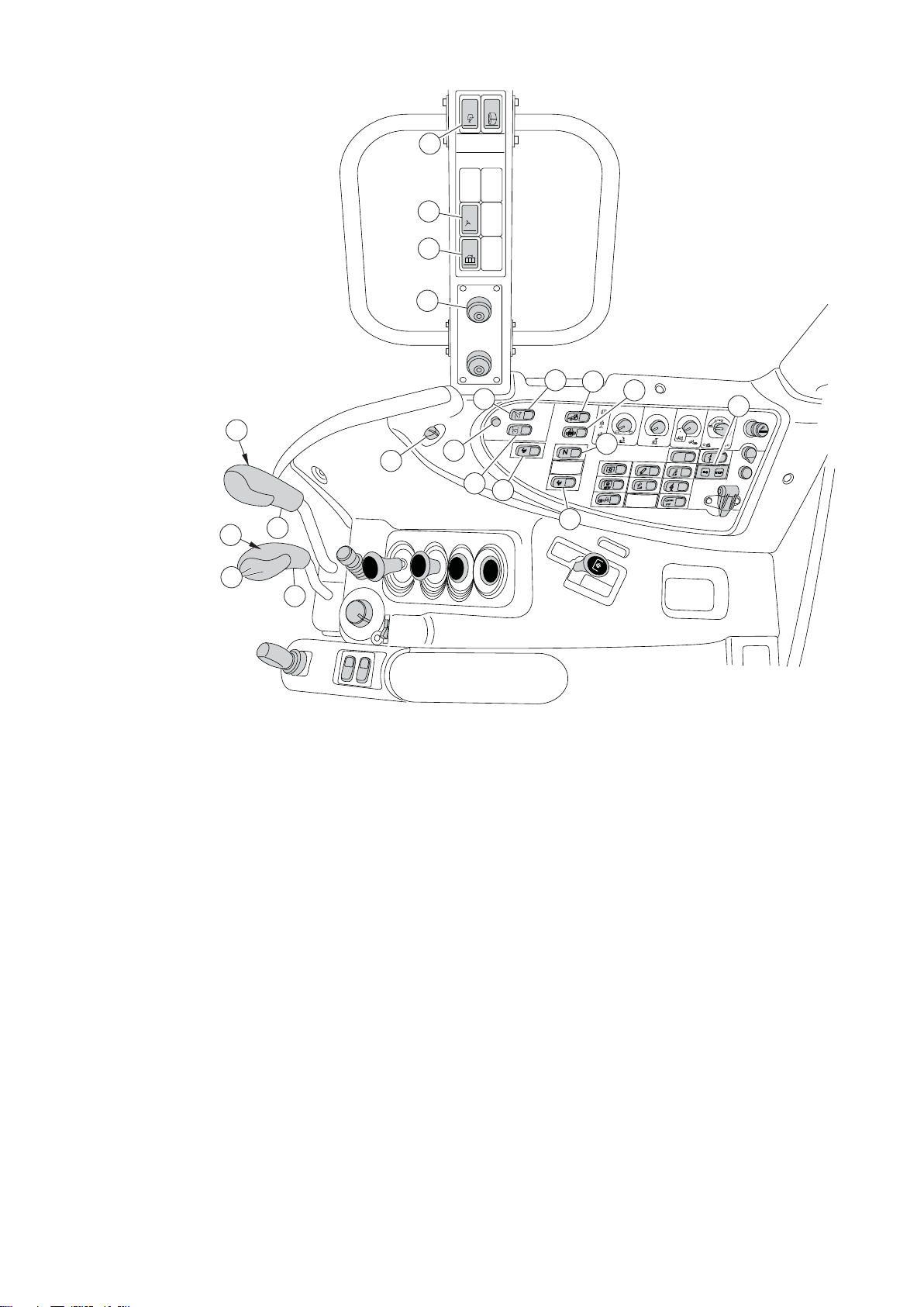
A
U
T
O
A
U
T
O
M
I
N
M
A
X
P
O
N
G
P
S
OF
F
A
U
T
O
1
2
3
2
3
4
5
7
11
14
13
12
15
8
16
18
17
19
20
1
6
9
10
2. Instruments and controls
GUID-D3FB5950-8998-46FE-BE63-EDEFDE806389
1. AutoComfort cabin suspension system (extra equipment)
2. Activation switch for Auto-Steering (extra equipment)
3. Change switch for A-pillar display views
4. Auto-Steering terminal connector
5. Cruise control (Cruise panel) (extra equipment)
6. Cruise control setting switch; the constant driving speed/engine revs (extra
equipment)
7. Switch for four wheel drive (4WD)
8. Hand throttle
9. Cruise control off-switch (extra equipment)
10. Cruise control setting switch (extra equipment)
11. Switch for differential lock
12. Switch for Powershift-automatics
13. Switch for automatic traction control
14. STOP indicator light (red)
15. Powershift rocker switch for reverse drive tractor (extra equipment)
16. Switch for HiShift (extra equipment)
17. Range gear lever
18. Switch for HiShift (extra equipment)
19. Push buttons for Powershift operation
20. Speed gear lever
- 35 -
Page 37
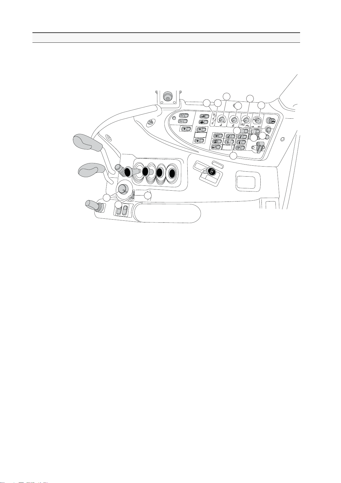
A
U
T
O
A
U
T
O
M
IN
M
A
X
P
111 222
333
444
555
666
999
888
777
101010
131313
121212
111111
2. Instruments and controls
2.4.2 Linkage
Rear linkage
GUID-2CE59CFA-242A-4FFA-B103-4BEAB2FA6AB5
1. Diagnose light
2. Lift/lower indicator lights
3. Lowering speed selector
4. Transport height selector
5. Draft control selector
6. Drive balance control, including slip control system, on Autocontrol D (ACD)
linkage (extra equipment)
7. Draft control indicator light, on Autocontrol D (ACD) linkage (extra equipment)
8. Drive balance control light
9. Slip control light, on Autocontrol D (ACD) linkage (extra equipment)
10. Inner switch for connecting implement (corresponding push buttons located
on both mudguards)
11. Position control knob
12. Passing switch for position control knob
13. Lift/stop/lower switch
Front linkage
Front linkage is extra equipment.
- 36 -
Page 38
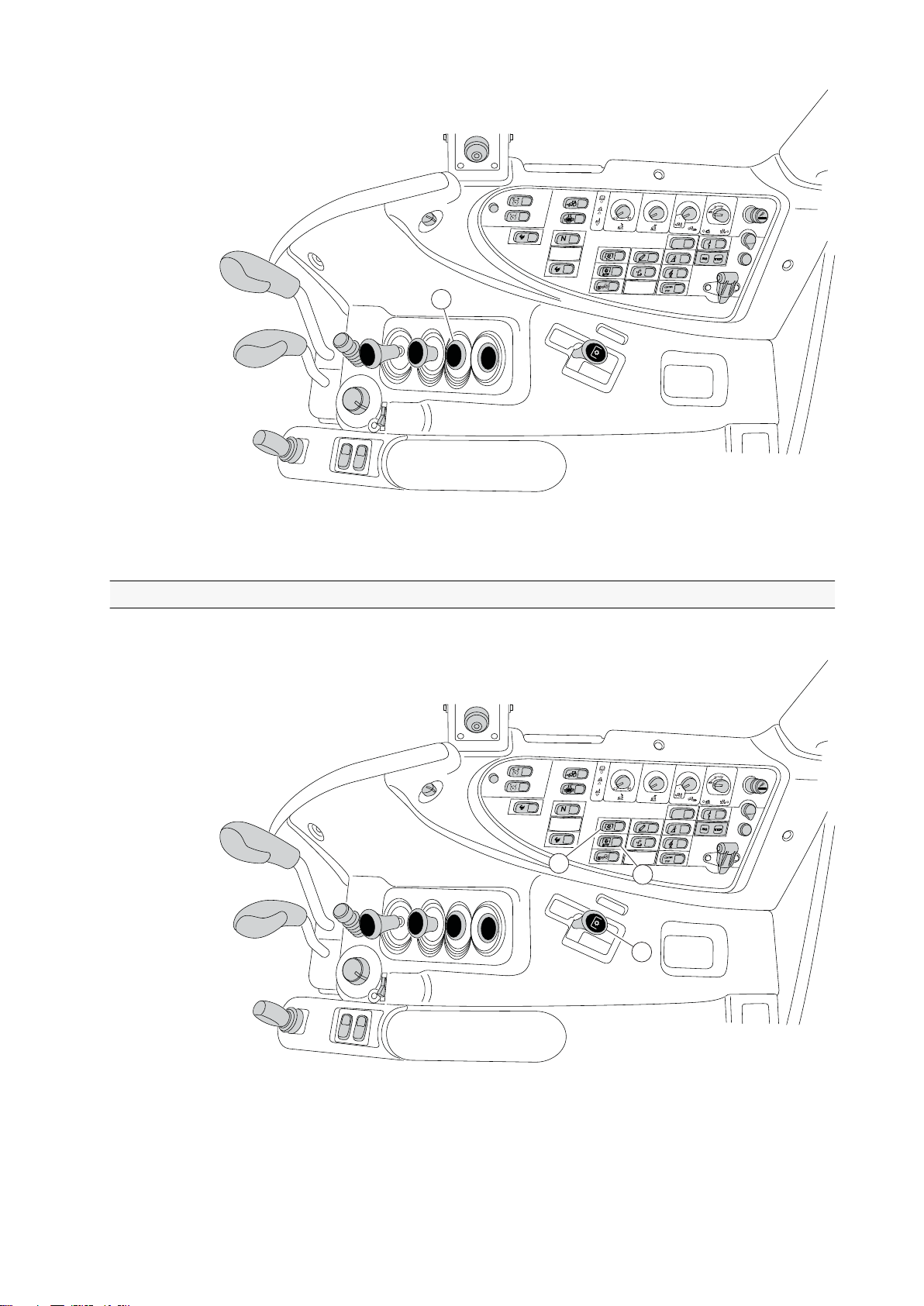
A
U
T
O
A
U
T
O
M
IN
M
A
X
P
111
A
U
T
O
A
U
T
O
M
IN
M
A
X
P
333
222
111
2. Instruments and controls
GUID-E3CF7018-A349-4131-B25F-6512E01EEF5A
1. Control lever, auxiliary hydraulics block 3
2.4.3 Power take-off
Rear power take-off
GUID-04B371AB-422B-4998-AB56-A82D3F3EEC58
1. Switch for rear power take-off (PTO)
2. Switch for the rear PTO automatic stop
3. Speed control lever for the rear PTO
- 37 -
Page 39

A
U
T
O
A
U
T
O
M
IN
M
A
X
P
111
2. Instruments and controls
Front power take-off
Front power take-off (PTO) is extra equipment.
GUID-6F81C523-F8B4-45EB-B153-D786F69791EC
1. Switch for front PTO
- 38 -
Page 40
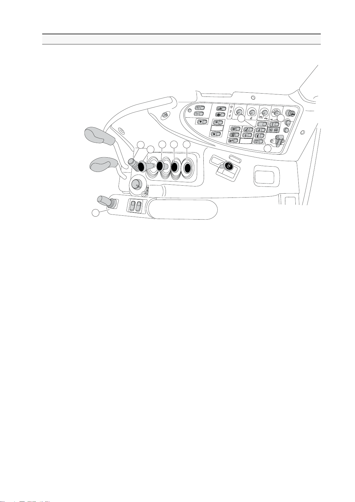
2.4.4 Auxiliary hydraulics
A
U
T
O
A
U
T
O
M
I
N
M
A
X
P
4
9
5
67 8
333
222
111
The following instruments and controls are used to control the auxiliary hydraulics.
2. Instruments and controls
GUID-387CDB30-6B3D-4B84-9E40-18F0D183EE6E
1. Release switch for equipment locking (extra equipment)
2. Main switch for the hydraulic loader
3. Switch for Softdrive (extra equipment)
4. Flow control valve (extra equipment)
5. Control lever for valve block 1
6. Control lever for valve block 2
7. Control lever for valve block 3 (extra equipment)
8. Control lever for valve block 4 (extra equipment)
9. Extra arm rest, electrically controlled front loader valves (extra equipment)
- 39 -
Page 41

1
2
3
8
7
10
11
6
5
4
9
AUTO
AUT
O
M
I
N
M
A
X
P
2. Instruments and controls
2.4.5 Other controls
GUID-698E735D-CC91-4EE9-8045-7CADF77D2869
1. Mounting brackets (extra equipment)
2. Implement signal connection (extra equipment)
3. Lighter/power outlet
4. Switch for trailer hitch hydraulic unlatching/locking (extra equipment)
5. Control stop switch (extra equipment)
6. Indicator light for implement signal connection (extra equipment)
7. 3-pin power socket
8. 2-pin power sockets (lower socket is extra equipment)
9. Place for implement remote control
10. Storage compartment
11. Trailer hitch release control (extra equipment)
- 40 -
Page 42

2.5 Controls on the rear side
1
2.5.1 Rear window opening device
GUID-B7032200-07B2-42CA-B684-4CFFD8A5D05E
1. Rear window opening device
2. Instruments and controls
- 41 -
Page 43

1
2
3
4
5
6
7
8
9
10
2. Instruments and controls
2.5.2 Reverse drive system controls
The reverse drive system is extra equipment.
GUID-46A04C31-37E6-4B81-B954-DA1D61C958B1
1. Switch for Powershift, (3---steps)
2. STOP indicator light (red)
3. A-pillar display
4. Power shuttle lever
5. Powershift preprogramming push button
6. Lever for adjusting steering wheel inclination
7. Steering wheel
8. Clutch pedal
9. Brake pedal
10. Accelerator pedal
- 42 -
Page 44

2.6 Controls on the left-hand side
1
3
4
2
The following controls are positioned on the left-hand side.
2. Instruments and controls
GUID-1C4499EA-A11D-4133-91B6-2493C4FAE430
1. Side window opening handle
2. Storage compartment or place for ash tray, extra equipment
3. Storage compartment
4. Emergency brake, extra equipment
- 43 -
Page 45

5 6 5 7
3
4
1 2
2. Instruments and controls
2.7 Controls on the front roof console
The following controls are positioned in the front roof console.
GUID-0B01F055-1E97-497A-9EC2-7EF32CF8F11D
1. Cab light
2. Recirculation control lever (not with automatic air conditioning)
3. Mirror heating, extra equipment
4. Mirror adjustment, extra equipment
5. Ventilation nozzles
6. Sun visor down
7. Sun visor up
- 44 -
Page 46

1 2
3 4
5 6
7
8
9
2. Instruments and controls
2.8 Controls on the right-hand side roof console
The following figure shows the components on the right-hand side roof console.
GUID-8C6EF57D-4FFF-47AF-B5AC-2E6430341506
1. Radio (extra equipment)
2. Rotating warning light switch (extra equipment)
3. Front working lights switch
4. Rear working lights switch
5. Front waist working lights switch (extra equipment)
6. Rear waist working lights switch (extra equipment)
7. Trailer hitch light switch (extra equipment)
8. Rear window wiper switch (extra equipment)
9. Rear window washer switch (extra equipment)
- 45 -
Page 47

0
1
2
3
4
1 2 4 5 6 9 10
11
7
12
83
3 41
2
2. Instruments and controls
2.9 Controls on the forest equipment right-hand side roof console
GUID-95C88AA8-4355-44D4-B842-88C65570C2DA
1. Fan control knob
2. Temperature control knob
3. Floor fan switch (extra equipment)
4. Rotating warning light switch (extra equipment)
5. Front working lights switch
6. Rear working lights switch
7. Front waist working lights switch (extra equipment)
8. Rear waist working lights switch (extra equipment)
9. Trailer hitch light switch (extra equipment)
10. Rear window wiper switch (extra equipment)
11. Rear window washer switch (extra equipment)
12. Rear window heater switch (extra equipment)
2.10 Controls on the left-hand side roof console
The following figure shows the components on the left-hand side roof console.
GUID-9A5C2E2B-EA01-4E4C-B9A5-AF292AF1D1B5
1. Fan control knob
2. Temperature control knob
3. Floor fan switch (extra equipment)
4. Rear window heater switch (extra equipment)
- 46 -
Page 48

1
2
3
1
2. Instruments and controls
2.11 Controls on the forest equipment left-hand side roof console
GUID-C79687A2-5647-4F66-975D-2EC3BF1191A3
1. Radio (extra equipment)
2.12 Air conditioning controls
2.12.1 Manual air conditioning controls
The manual air conditioning system is extra equipment.
GUID-FC188211-EA1D-4F1F-9AE8-94E1C4CEE5C3
1. Fan control knob
2. Air conditioning control knob
3. Recirculation control knob
- 47 -
Page 49

1 2 3
4 5
6
2. Instruments and controls
2.12.2 Automatic air conditioning controls
The automatic air conditioning system is extra equipment.
GUID-8EEFE0E5-2C8D-4CE0-BA9D-FE61034A548D
1. Fan control knob
2. Display
3. Temperature control knob
4. Air conditioning system on/off button
5. Defrosting button
6. Recirculation control button
- 48 -
Page 50
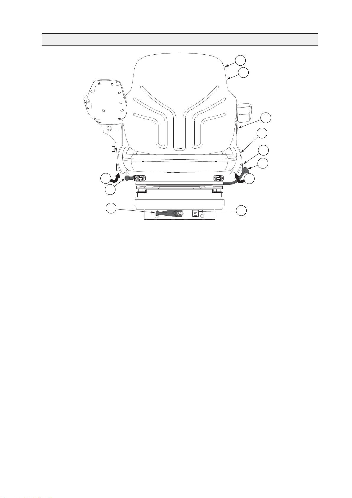
2.13 Driver's seat
1
2
3
4
5
6
7
7
8
9
10
2. Instruments and controls
GUID-09C4AD34-233B-4AEA-A328-C128E709298D
1. Storage compartment for manuals
2. Seat heating
3. Armrest adjustment
4. Backrest inclination adjustment
5. Seat belt anchor point
6. Seat turning lock/release
7. Height adjustment
8. Forward/backward adjustment
9. Suspension adjustment
10. Operator weight display
- 49 -
Page 51
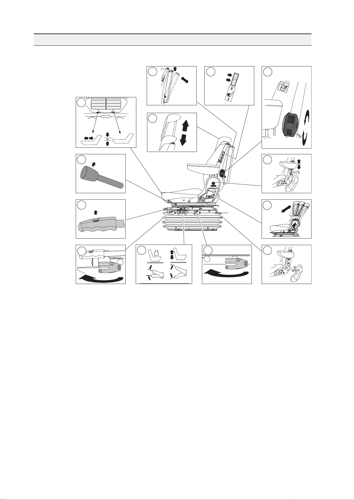
2
3
6
off
on
4
5
8
1
7
9
10
12
13
11
2. Instruments and controls
2.14 Air suspended driver's seat
Air suspended driver's seat is extra equipment.
GUID-F4AF8B6A-BF95-48FE-8238-12635155227D
1. Seat depth and cushion angle adjustment
2. Storage compartment for manuals
3. Headrest height adjustment and removal
4. Seat heating
5. Lumbar support adjustment
6. Seat turning lock/release
7. Armrest adjustment
8. Forward/backward adjustment
9. Backrest inclination adjustment
10. Longitudinal suspension adjustment
11. Height and vertical suspension adjustment
12. Suspension stiffness adjustment
13. Seat belt anchor point
- 50 -
Page 52
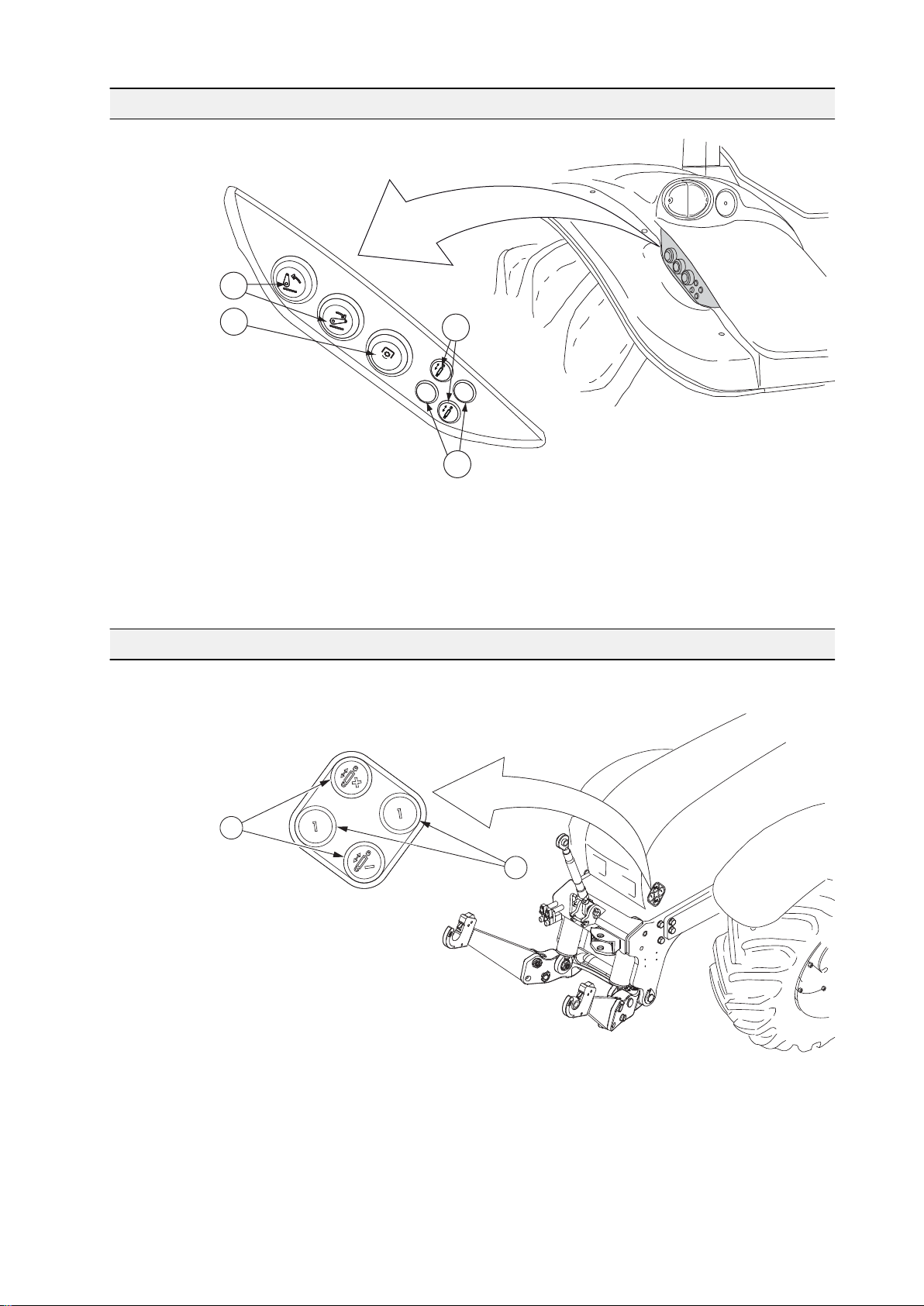
2.15 Controls on the rear mudguard
ON/OFF
1
1
2
4
3
1
1
2
GUID-1379ECEF-F861-40EB-9109-14E7C7D2BAD8
2. Instruments and controls
1. Lift/lower push buttons
2. Rear power take-off on/off push button (extra equipment)
3. On/off valve 1 push buttons (extra equipment)
4. Rear valve 1 push buttons (extra equipment)
2.16 Controls on the bonnet
The following controls are positioned on the bonnet.
GUID-0B4D2F6C-0D5D-4C94-995A-6247BFA3641F
1. Lift/lower push buttons for the front linkage
2. Front quick couplings push buttons
- 51 -
Page 53
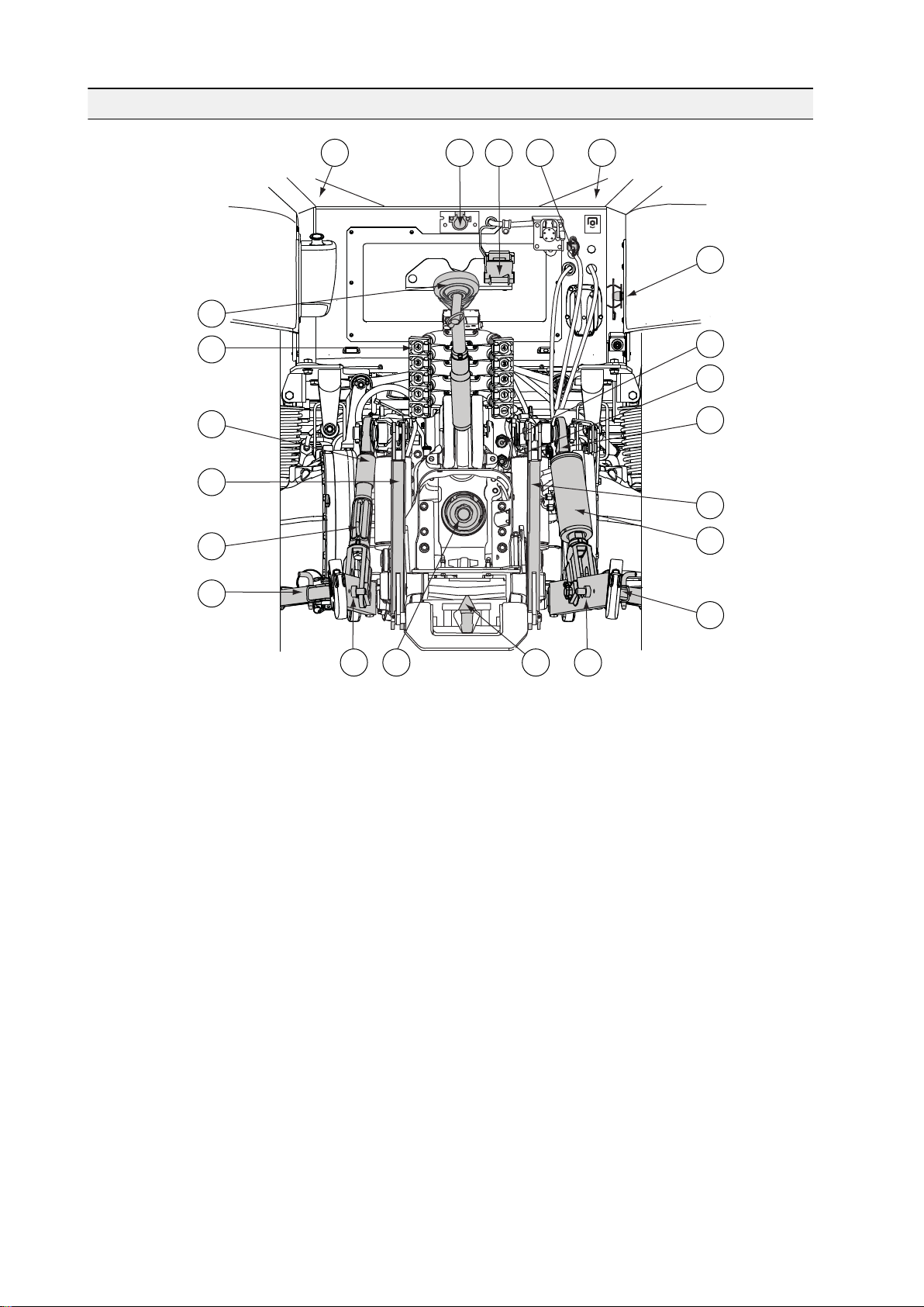
STOP
STOP
2
4
6
1
1
7
12
8
9
10
11
11
15
15 16 17
8
14
5
3
9
13
2. Instruments and controls
2.17 Rear controls and connections outside the cab
GUID-4A68A574-BFB0-4375-A301-58C6F10E6532
1. Inlet, remote control cables
2. Trailer socket
3. Trailer coupling Duo-Matic (extra equipment)
4. Emergency stop plug for rear power take-off (PTO)
5. Hitch ball storing bracket
6. Top link
7. Quick-action couplings, auxiliary hydraulics
8. Lifting links
9. Pick-up hitch lifting links (extra equipment together with the pick-up hitch)
10. Levelling gear
11. Check links
12. Auxiliary hydraulic system return coupling
13. Quick-action coupling for the trailer brakes (extra equipment)
14. Hydraulic levelling ram (extra equipment)
15. Lower links
16. PTO shaft
17. Pick-up hitch (extra equipment)
The pick-up hitch is extra equipment with many alternatives.
- 52 -
Page 54
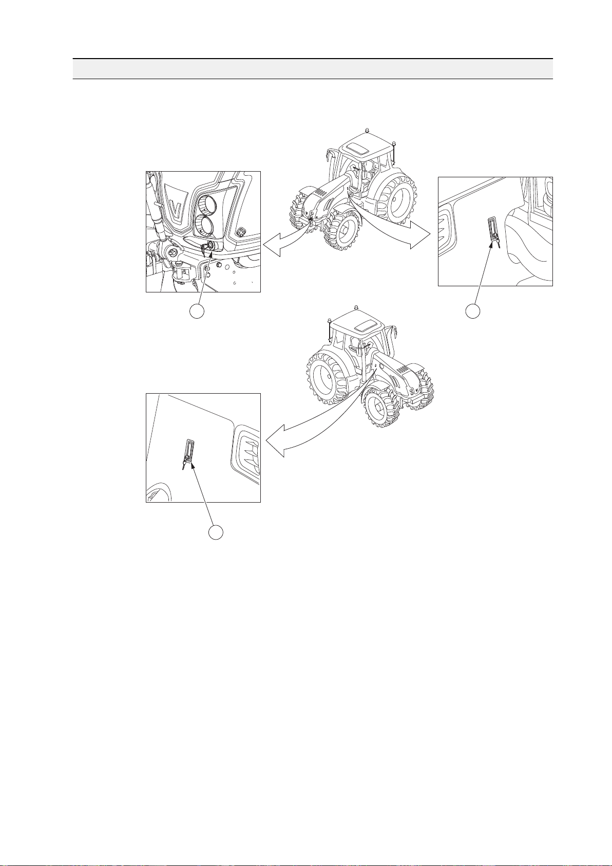
2.18 Engine hood locking
1 2
3
Engine hood and the side plates are locked. You can open the hood and the side
plates with the separate keys delivered with the tractor.
2. Instruments and controls
GUID-FEED73CF-6F31-4E86-8920-E416F8B95902
1. Engine hood lock.
2. Side plate lock on the left side.
3. Side plate lock on the right side.
- 53 -
Page 55

3. Operation
3 Operation
3.1 Running the tractor in
The tractor is run in during the 50 first hours of use. Running the tractor in
correctly gives the tractor a longer service life and makes it more economical.
Before you start driving, make sure that:
• You understand all the instruments and the functions of the controls.
• You have read the safety precautions.
IMPORTANT: Check that all bolts and nuts, for example in the wheels and
exhaust system, are properly tightened.
IMPORTANT: Carry out the daily maintenance before you drive the tractor for the
first time each day.
When running the tractor in:
• Drive smoothly and vary the loading.
• Do not race the engine.
• Do not run the engine at maximum speed.
• Do not pull a heavy load at low engine speed.
• Avoid driving with the same gear engaged and at the same engine speed for
a long period at a time.
Check all instruments immediately after the engine has started. Keep an eye on
the instruments while driving.
3.2 Preparing for use
Before you start using the tractor, read this manual thoroughly.
• Make sure that the tractor is handled and maintained in the correct way to
ensure reliability and provide economical operation.
• Follow the maintenance program carefully and include the daily maintenance
in your normal routine.
• Only use genuine Valtra spare parts for optimum performance.
3.2.1 Adjusting the driver's seat
You can adjust the driver's seat according to your height and weight. With these
adjustments you can minimize the exposure to vibration, obtain the best support
for your lower back and get the most comfortable driving position. Note that you
may need to change the adjustments according to work conditions or the
components you are using such as the tyre type.
- 54 -
Page 56
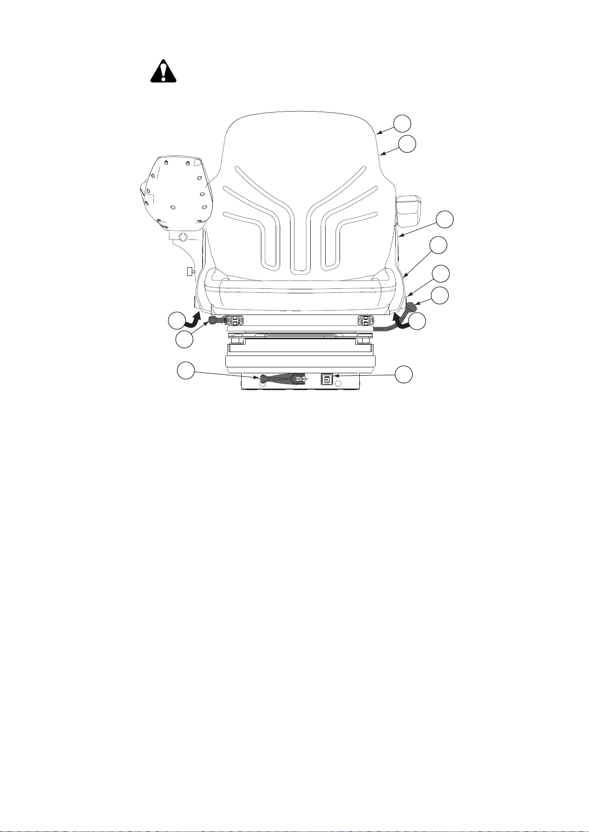
1
2
3
4
5
6
7
7
8
9
10
3. Operation
CAUTION: Do not attempt to adjust the seat while driving. There is an
increased risk of loss of control.
GUID-09C4AD34-233B-4AEA-A328-C128E709298D
1. Storage compartment for manuals
2. Seat heating
3. Armrest adjustment
4. Backrest inclination adjustment
5. Seat belt anchor point
6. Seat turning lock/release
7. Height adjustment
8. Forward/backward adjustment
9. Suspension adjustment
10. Operator weight display
• Turn the seat.
• Pull the locking lever upwards to release the lock.
• Turn the seat 180° anti-clockwise to the desired position.
The seat has set positions at intervals of 10°, to be used, for example,
when ploughing.
• Adjust the seat forwards or backwards.
• Pull up the forward/backward adjustment lever.
• Move the seat to the desired position.
- 55 -
Page 57

3. Operation
• Adjust the suspension.
The operator weight display shows the settings for operators of different
weights.
• To increase the suspension, turn the suspension adjustment lever
clockwise.
• To decrease the suspension, turn the suspension adjustment lever anti-
clockwise.
• Adjust the height of the seat.
You can lift the seat from the basic position to two higher positions.
• To lift the seat, pull it slowly upwards until you hear a click.
• To lower the seat, pull it up to the top position and then let it to drop to
the desired position.
• Fasten the seat belt to the anchor point on the seat.
• Adjust the backrest inclination.
• Pull up the backrest inclination adjustment lever.
• Set the backrest to the desired position.
• Adjust the left armrest.
• Remove the cover.
• Change the armrest position in the mounting slot.
• Turn the seat heating on or off.
3.2.2 Adjusting the air-suspended driver's seat
You can adjust the air-suspended driver's seat according to your height and
weight. With these adjustments you can minimize the exposure to vibration,
obtain the best support for your lower back and get the most comfortable driving
position. Note that you may need to change the adjustments according to work
conditions or the components you are using such as the tyre type. The airsuspended driver's seat is extra equipment.
CAUTION: Do not attempt to adjust the seat while driving. There is an
increased risk of loss of control.
- 56 -
Page 58

2
3
6
off
on
4
5
8
1
7
9
10
12
13
11
3. Operation
GUID-F4AF8B6A-BF95-48FE-8238-12635155227D
1. Seat depth and cushion angle adjustment
2. Storage compartment for manuals
3. Headrest height adjustment and removal
4. Seat heating
5. Lumbar support adjustment
6. Seat turning lock/release
7. Armrest adjustment
8. Forward/backward adjustment
9. Backrest inclination adjustment
10. Longitudinal suspension adjustment
11. Height and vertical suspension adjustment
12. Suspension stiffness adjustment
13. Seat belt anchor point
• Adjust the seat depth and cushion angle.
• To adjust the seat depth, pull up the right handle in the seat front.
• To adjust the seat cushion angle, pull up the left handle in the seat front.
• Turn the seat.
• Release the lock by pulling the lock/release lever upwards.
• Turn the seat to the desired position.
The seat has set positions from 180° anti-clockwise to 30° clockwise at
intervals of 10°.
- 57 -
Page 59

3. Operation
• Adjust the seat forwards or backwards.
• Pull the forward/backward adjustment lever upwards.
• Move the seat forwards or backwards to the desired position.
• Turn the longitudinal suspension on or off.
• To turn on the longitudinal suspension, turn the lever to the rear position.
• To turn off the longitudinal suspension, turn the lever clockwise 180° to
the front position.
• Adjust the suspension according to the operator weight.
• Pull the suspension adjustment lever until the compressor starts.
The compressor runs and the suspension adjusts automatically
according to the operator's weight.
If the operator is lighter than the previous operator, the compressor runs
momentarily, the excess pressure is released, and the seat lowers.
The suspension setting remains stored in the seat memory even if the
tractor is switched off.
The seat suspension travel is 100 mm (± 50 mm) regardless of the
starting height. The suspension area is limited to 100 mm for safety
reasons.
• Adjust the height of the seat.
The seat has a stepless height adjustment range of 80 mm (±40 mm from the
seat middle position).
• Lift the seat by pulling the height adjustment lever upwards until the
desired height is reached (the compressor runs continuously).
When the lever is released, the compressor stops and the seat stays at
that height. If you set the seat too high so that the room for upward
movement is less than 50 mm, the seat lowers automatically to the
highest permissible position.
• Lower the seat by pressing the height adjustment lever downwards until
the desired height is reached.
If you set the seat too low so that the 50 mm downward suspension is not
possible, the seat automatically rises to the lowest limit the next time you
touch the lever.
If you sit very still on the seat during the adjustment, the seat may rise to
the previous height in the memory.
When the seat is locked at a new height, you hear a faint click.
• Adjust the stiffness of the seat suspension.
• When the lever is at the back position, the suspension is at its firmest.
• When the lever is at the front position, the suspension is at its softest.
• Fasten the seat belt to the anchor points on the seat.
• Adjust the backrest inclination.
• Pull the backrest inclination lever up.
• Set the backrest to the desired position.
• Adjust the armrest.
• Remove the cover.
• Change the armrest position in the mounting slot.
- 58 -
Page 60

• Adjust the lumbar support.
Turn the knob clockwise or anti-clockwise to adjust the lumbar support. The
height and depth are adjusted at the same time.
• Turn the seat heating on or off.
• Adjust the headrest height by lifting or lowering it.
• Remove the headrest by pulling it upwards.
3.2.3 Adjusting the armrest
3. Operation
GUID-8B7C0B54-A62B-42EC-8B2F-3CDECEAA85F3
1. Declination adjustment screw
2. Length adjustment screw
3. Bracket
• Adjust the armrest inclination.
• Turn the declination adjustment screw clockwise to lift up the armrest.
• Turn the declination adjustment screw anti-clockwise to lower the armrest.
• Raise the armrest to the upright position by lifting the front edge.
• Adjust the length of the armrest.
• Loosen the length adjustment screw.
• Adjust the length of the armrest.
• Tighten the length adjustment screw.
• Adjust the armrest laterally by moving the end part sideways.
• Adjust the vertical position of the armrest by moving the bracket to other
mounting holes.
- 59 -
Page 61

2
1
3. Operation
3.2.4 Adjusting the steering wheel
You can adjust the steering wheel position with the lever and the locking pedal.
CAUTION: Do not adjust the steering wheel position while driving.
GUID-D702F6C1-5668-46E9-B84A-6175FC7A0A9D
1. Lever for adjusting steering wheel position
2. Locking pedal for steering wheel inclination
• Adjust the steering wheel position.
• Push the lever downwards.
• Move the steering wheel up or down to the wanted position.
• Pull the lever up to lock the steering wheel position.
• Set the steering wheel inclination.
• Press the locking pedal down.
• Adjust the steering wheel inclination.
You can move the steering wheel to 9 different positions.
• Release the pedal after adjusting.
- 60 -
Page 62

3.2.5 Adjusting standard mirrors
1
1
You can adjust the position of the standard mirrors manually.
GUID-94073A8E-5075-4F2D-A9E9-581B1312B9E4
1. Locking device of the mirror support
1. Loosen the locking device of the mirror support.
3. Operation
2. Adjust the mirror position.
3. Tighten the locking device.
3.2.6 Adjusting optional mirrors
You can adjust the position of the optional mirrors electrically.
GUID-8BA97365-1C8D-43C9-96A2-10A4AA230C0F
1. Mirror adjustment
• To adjust the left mirror, turn the knob to the left and push the knob in the
direction of the arrows.
• To adjust the right mirror, turn the knob to the right and push the knob in the
direction of the arrows.
- 61 -
Page 63

1
1
3. Operation
3.2.7 Heating mirrors
Mirror heating is extra equipment.
GUID-F15F3525-F6B6-4020-A3C1-387FE9F0497F
1. Mirror heating switch
• To switch the mirror heating on, press down the symbol side of the switch.
• To switch the mirror heating off, press down the side of the switch opposite to
the symbol.
3.2.8 Using the windscreen wiper and washer
GUID-67100B24-DF6C-4F9B-9EA7-D9B8AEFB23C9
1. Multifunctional lever
• To use the windscreen wiper, turn the multifunctional lever.
The wiper has a drizzle position and two speeds.
• To use the windscreen washer, push the control lever inwards.
3.2.9 Using the rear window heater
Rear window heater is extra equipment.
1. To switch the rear window heater on, press down the symbol side of the switch.
- 62 -
Page 64
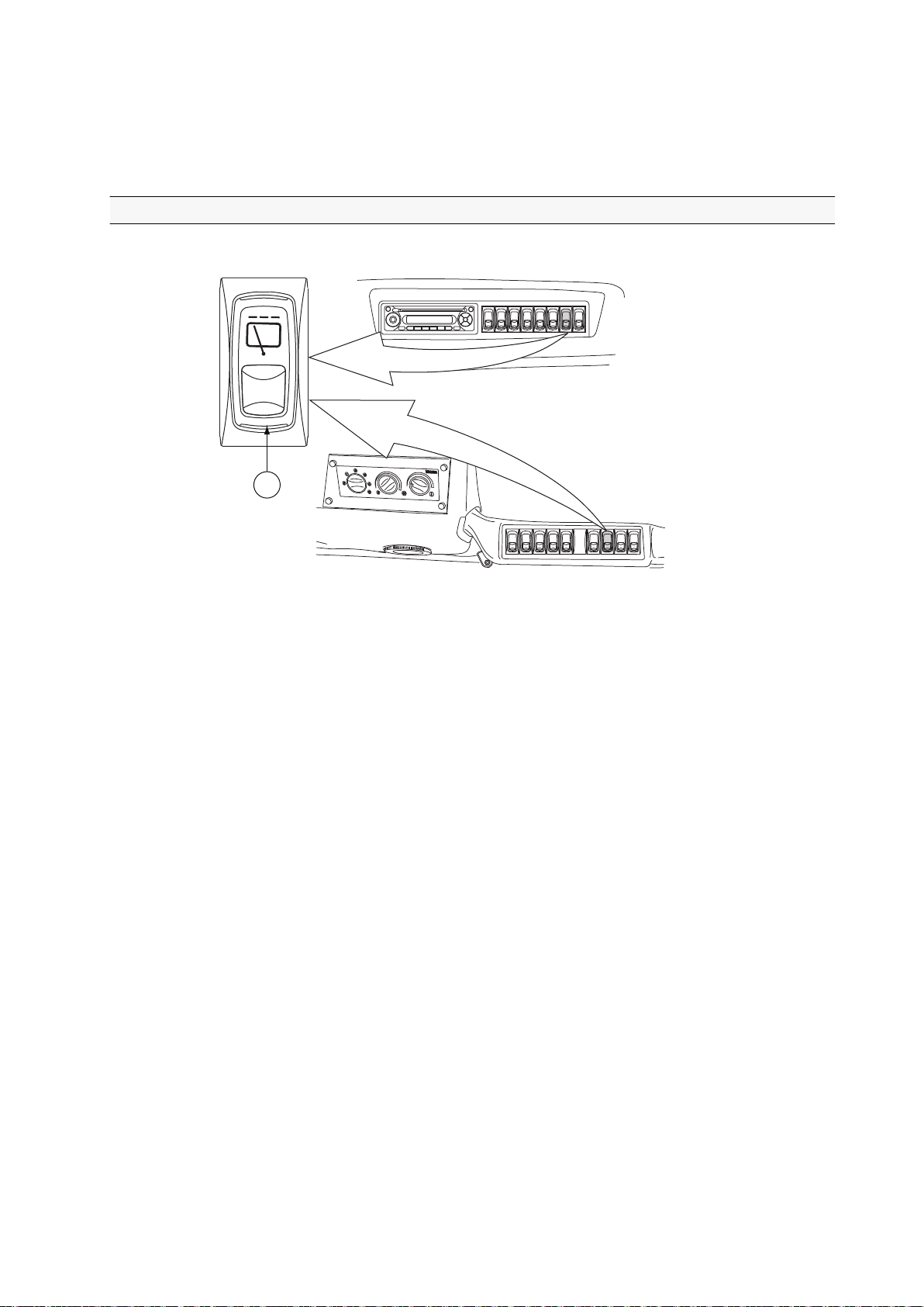
2. To switch the rear window heater off, press down the switch opposite to the
1
symbol.
If the rear window heater is not manually switched off, it switches off
automatically after 10 minutes.
3.2.10 Using the rear window wiper
The rear window wiper is extra equipment.
3. Operation
GUID-62DA5F9E-6427-4CD2-B800-3EF2B7F49346
1. Switch for the rear window wiper
• To turn on the rear window wiper, press down the symbol side of the of the
rear window wiper switch.
• To turn on the drizzle function, press the rear window wiper switch to the
centre position.
• To turn off the rear window wiper, press down the side opposite to the
symbol of the of the rear window wiper switch.
- 63 -
Page 65
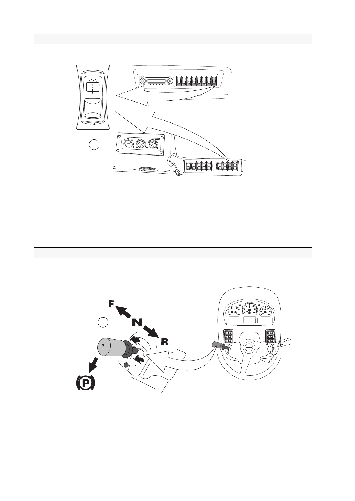
1
1
3. Operation
3.2.11 Using the rear window washer
The rear window washer is extra equipment.
GUID-02281C37-69A5-4001-B126-F0C7196D7262
1. Switch for the rear window washer
• To turn on the rear window washer, press down the symbol side of the switch.
The switch for the rear window washer is spring returned.
• To turn off the washer, press down the side of the switch opposite to the symbol.
3.2.12 Power shuttle lever
With the power shuttle lever you can change the driving direction and apply the
parking brake.
GUID-85975454-7178-48B4-A4A3-344CB5D07905
1. Power shuttle lever
• F (front position) = forward driving direction
• N (centre position) = neutral
• R (rear position) = reverse driving direction
• P = parking brake position
- 64 -
Page 66

With the power shuttle, you can change the driving direction without using the
1
clutch pedal. However, traditional use of the clutch pedal is still possible when
changing direction, just make sure that you press the pedal fully down before
moving the power shuttle lever.
• With the power shuttle lever in the centre position, the parking brake can be
applied.
• When applying the parking brake, the four-wheel drive (4WD) is engaged and
all wheels brake.
• When the power is turned off, the parking brake is automatically applied
independently of the power shuttle lever position.
3.2.13 Using the main switch
IMPORTANT: The main power can be switched off only when the ignition key is
in the STOP position.
3. Operation
GUID-80ABD553-4F90-46C9-B3FA-D951E7ADBB67
1. Main switch
The main switch is spring returned on both sides.
• To switch on the main power, press the symbol side of the main switch.
• To switch off the main power, press the side of the main switch opposite to
the symbol.
When the main power is switched off, power is supplied only to the radio and
instrumentation.
• To switch off the main switch in an emergency, follow the steps below.
• Switch off the main power by turning the ignition key to the STOP position.
• Press the side of the main switch opposite to the symbol and,
simultaneously, the symbol side of the instrument panel display changeover switch.
3.2.14 Control stop
The control stop is used when the tractor is running an implement in stationary
mode (for example a compressor or pump) and the operator is not in the cab.
Using the control stop reduces the risk of more serious damage to the engine or
in the transmission. The control stop is extra equipment.
- 65 -
Page 67

1
AUTO
A
U
T
O
M
I
N
M
A
X
P
3. Operation
NOTE: When starting the engine, the control stop must be disengaged.
Otherwise the engine does not start.
NOTE: Do not use the control stop when driving. The control stop automatically
stops the engine if the stop light is lit.
IMPORTANT: If the control stop stops the engine, the fault must be found and
repaired before the engine is started again.
3.2.15 Using the control stop
GUID-0B6225B1-6D92-439A-9927-2531E65C387C
1. Control stop switch
• To activate the control stop, press down the symbol side of the control stop
switch.
Release the locking device by pushing it towards the middle of the switch.
• To deactivate the control stop, press down the side of the control stop switch
opposite to the symbol.
3.2.16 Using the ignition switch
WARNING: Do not turn the ignition key to the STOP position when
driving. When the power is off, the parking brake applies and all
wheels lock.
WARNING: If the engine stops while the tractor is moving (for
example, the fuel has run out), do not press the clutch pedal down.
When the tractor is moving and the transmission is engaged, the
engine is running and there is pressure in the system. When the clutch
pedal is pressed down, hydraulic pump does not run and there is no
hydraulic pressure in the system. If you press down the clutch pedal,
the steering deactivates and the parking brake engages.
WARNING: Do not keep extra keys on the same bunch with the
ignition key.It is possible that your knee touches them and turns the
power off.
The ignition switch has three positions: stop, power on and start.
- 66 -
Page 68
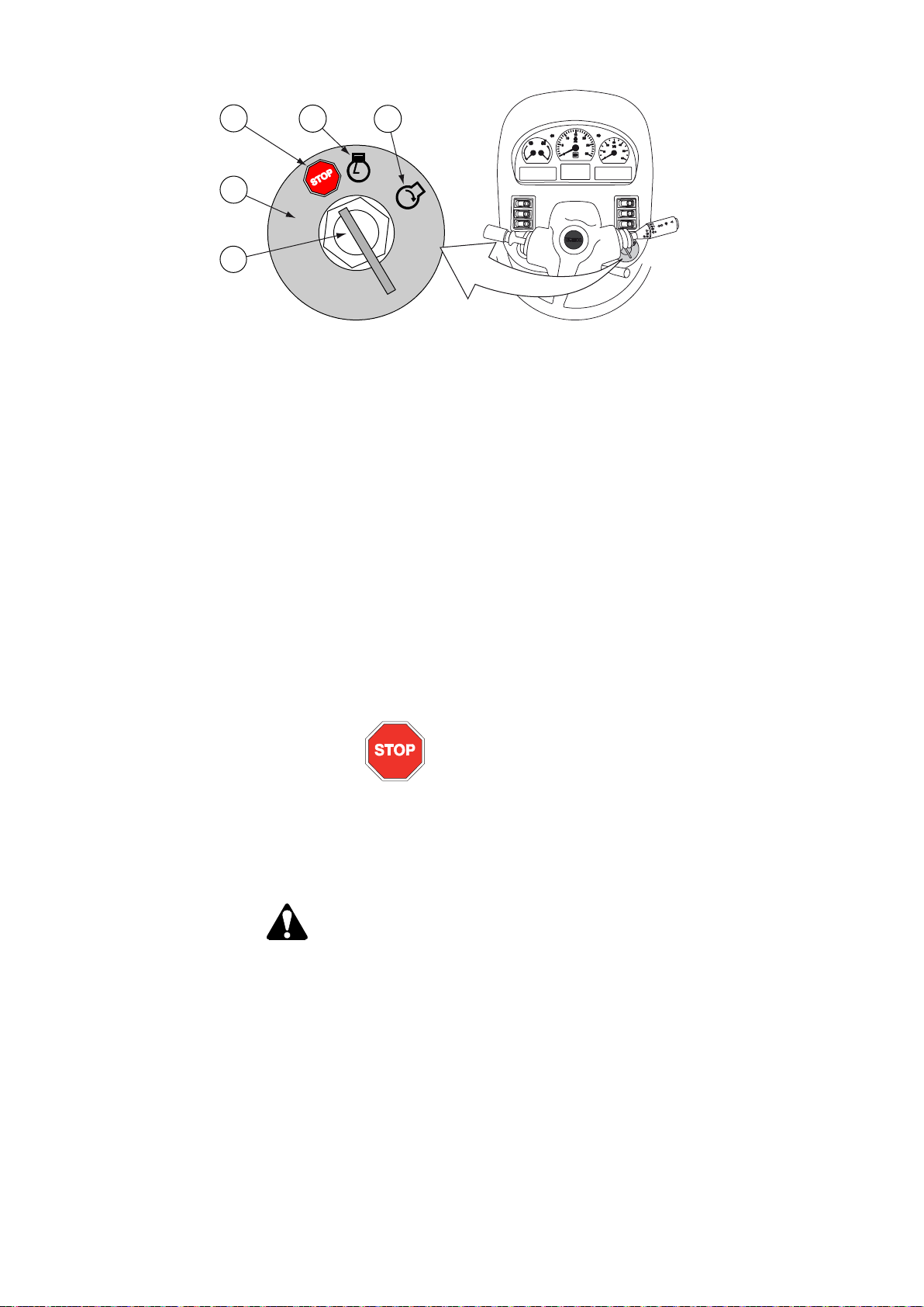
4
1
3
2
5
GUID-9B02020C-3389-4113-AFA0-CC49C784DA08
1. STOP position
2. Power on position
3. Start position
4. Ignition switch
5. Ignition key
3. Operation
• To turn on the power, turn the ignition key from the STOP position to the
power on position.
In cold conditions, when the engine is cold, the glow indicator light on the
Proline instrument panel is lit. When the ignition key is in this position,
electrical equipment can be used.
• To start the engine, turn the ignition key from the power on position to the
start position after the glow indicator light on the Proline instrument panel has
gone out.
• To turn off the power, turn the ignition key to the STOP position.
STOP position
• The STOP position of the ignition switch can be used as an emergency
stop. The tractor and several movements of the implements can be
stopped if a fault occurs by turning the ignition key to the STOP position.
This will make the engine stop, all the wheels lock, the transmission
disengage and the movement of the linkage stop.
WARNING: Do not turn off the power when the tractor is moving.
Turning off the power engages the parking brake immediately.
There is danger of skidding and loss of control.
- 67 -
Page 69
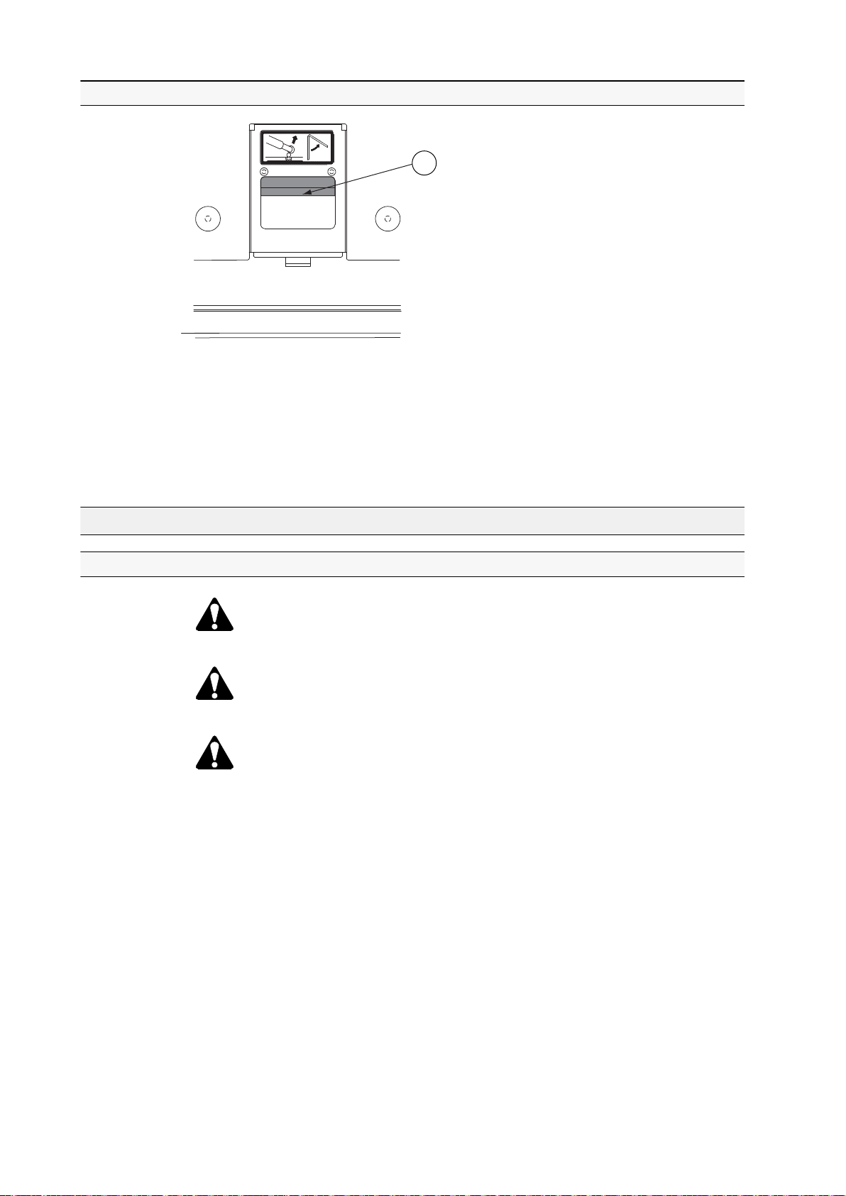
1
3. Operation
3.2.17 Using the roof hatch
GUID-F4D74D75-2B07-4BEF-BDE1-294251FDA043
1. Handle
1. • Open the hatch by pushing the handle forward and pushing the hatch
upward.
• Close the hatch by pushing the handle forward and pulling the hatch
downward.
3.3 Starting the tractor
3.3.1 Starting under normal conditions
WARNING: Never run the tractor in an enclosed building except with
the exhaust vented to the outside.
WARNING: Never start the engine unless you are seated on the
driver's seat.
CAUTION: Do not use starting aerosols. Due to the automatic glowing,
there is a risk of explosion.
IMPORTANT: If the engine fails to start on the first try, wait until the engine has
stopped completely before trying again.
When the power is turned on, all indicator lights in use are lit momentarily. The
following indicator lights remain on until the engine is started and the systems
operate normally:
- 68 -
Page 70
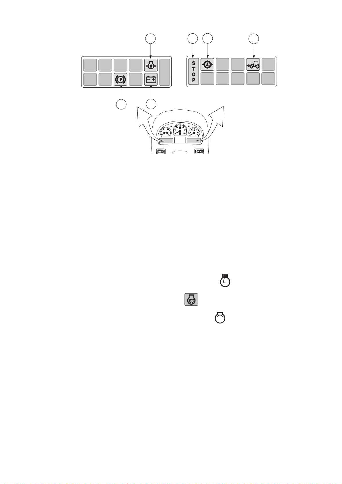
1
2
3
4
5
6
GUID-436251D4-B48E-4EEF-A554-E4C85B3B11BA
1. Engine oil pressure
2. Stop light (is flashing)
3. Gearbox oil pressure
4. Four-wheel drive
5. Parking brake
6. Battery charging
3. Operation
1. Check that the power shuttle lever is in the parking brake position.
2. Turn the hand throttle knob to the low idling position.
3. Switch on the main switch.
4. Ensure that the control stop (extra equipment) is deactivated.
5. Turn the ignition key to the power on position
6. Wait until the glow indicator light
7. Turn the ignition key to the starting position
• When the engine starts to fire up, keep the ignition key in the starting
position until the engine has started.
• If the engine fails to start within 10 seconds, stop starting and try again.
8. Release the ignition key when the engine starts.
When the engine starts, the following indicator lights go out:
• Engine oil pressure
• Gearbox oil pressure
• Stop light
• Battery charging
on the instrument panel has gone out.
.
.
9. Use the accelerator pedal to control the engine speed.
IMPORTANT: Never race a cold engine.
- 69 -
Page 71

3. Operation
After starting a cold engine, the glow indicator light can light up again. The
afterglow reduces white smoke and keeps the cold engine running smoothly.
3.3.2 Starting under cold conditions
To ensure a successful start under cold conditions, use the engine heater and
follow the instructions given.
IMPORTANT: If you start the engine when it is very cold, the indicator light for
blocked hydraulic filters can be lit. This indicates that the oil is going through the
by-pass valve unfiltered.
IMPORTANT: Avoid using hydraulics until the oil has warmed up and the
indicator light is no longer lit.
IMPORTANT: Always use the engine heater when the temperature is below 0°C.
IMPORTANT: If you are driving the tractor for a short distance only, make sure
that the battery is charged enough to ensure starting.
NOTE: Use of the engine heater reduces the wear on the engine.
• When cold starting the engine, turn off all unnecessary equipment that uses
electrical power.
• Keep the battery in a warm place when it is not in use.
Starting the tractor under very cold conditions is easier if the battery is kept in
a warm place when it is not in use.
• Use the engine heater to ensure a successful start under cold conditions.
Warming up the engine for 2–3 hours before starting is sufficient.
When the engine heater is activated, you can hear a hissing sound.
• If you start the engine under very cold conditions, keep the ignition key in the
starting position until the engine has started.
IMPORTANT: Do not keep the ignition key in the starting position for more
than 30 seconds at a time.
• If the temperature is below 0°C, first, warm up the engine and hydraulics oil
for a while at low engine speed.
Allow the engine to run for a few minutes before starting to drive or engaging
the power take-off. When first starting to use hydraulic functions, use the
predefined factory setting M2 to set the maximum flow to 50% for the first few
minutes.
• Never race a cold engine.
Run the engine with a light load until it has reached its normal operating
temperature.
- 70 -
Page 72
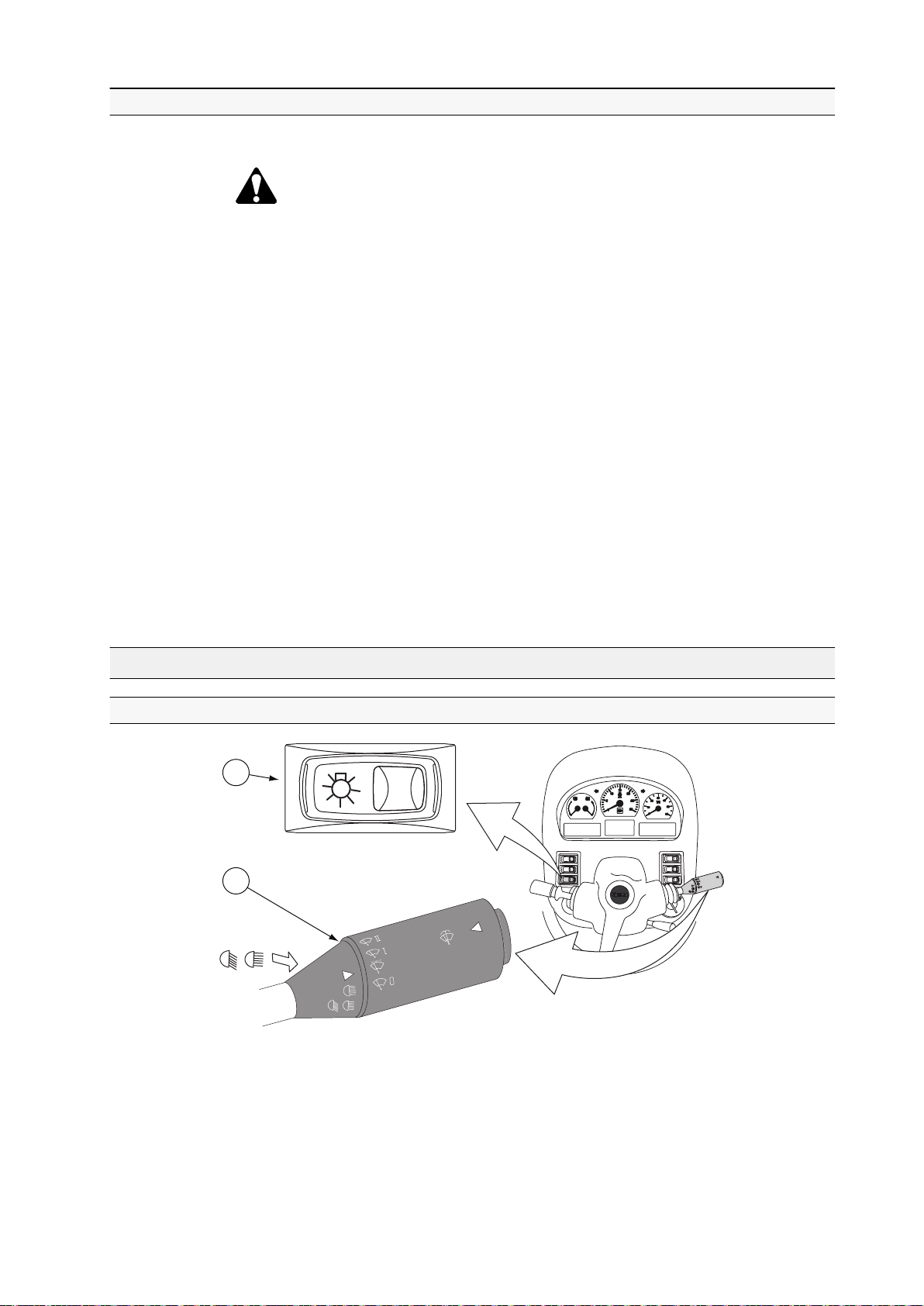
3.3.3 Starting with an auxiliary battery
1
2
You can start the engine with an auxiliary battery (jump starting).
WARNING: A fully charged battery connected directly to a dead
battery can cause a current surge capable of causing the batteries to
explode.
IMPORTANT: Never try to start the engine by short-circuiting leads.
1. Check that the auxiliary battery has the same voltage as the standard battery.
2. Open the battery plugs to avoid risk of explosion.
3. Connect the (+) terminal of the auxiliary battery to the (+) terminal on the
tractor battery.
4. Connect the other jump lead from the (-) terminal of the auxiliary battery to
the attaching bolt of the battery ground wire or some other convenient ground
(not to the battery terminal).
3. Operation
5. Start the engine.
6. When the engine has started, disconnect the jump leads in the following order:
• Disconnect the jump lead between the ground and the (-) terminal of the
auxiliary battery.
• Remove the jump lead between the (+) terminals.
3.4 Using lights
3.4.1 Using headlights
GUID-1272AE0F-D762-4BA3-B93D-720193D6D7C1
1. Light switch
2. Multifunctional lever
• To switch on the parking lights, turn the light switch to the centre position.
When the switch is in this position, the working lights can also be switched on.
- 71 -
Page 73
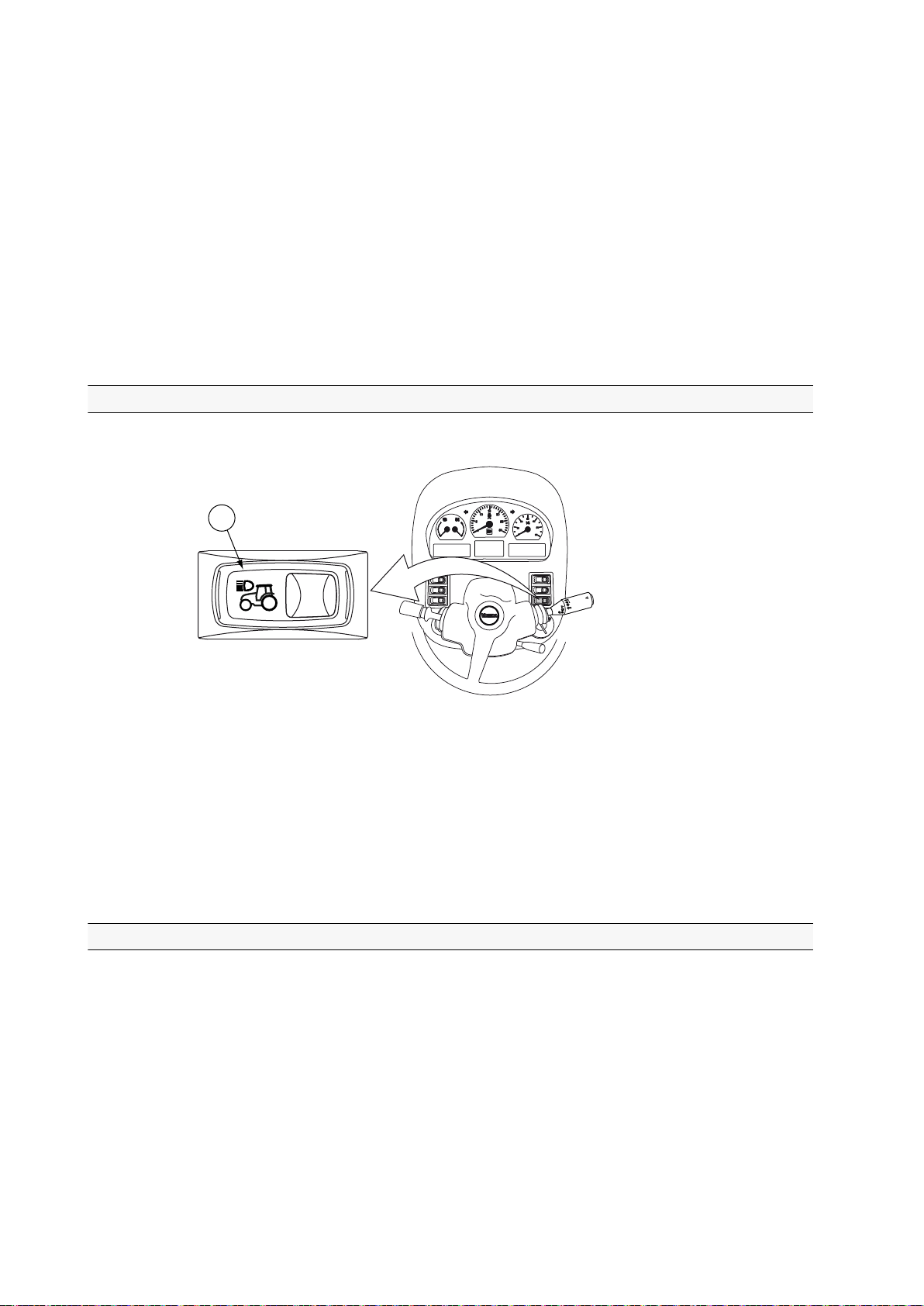
1
3. Operation
• To switch on the headlights, press down the symbol side of the light switch.
When the light switch is in this position, the main beams can be switched on
by the multifunctional lever.
NOTE: If the power is turned off when the headlights or parking lights are on,
the buzzer goes on. If lights are turned on when the power is off, the buzzer
does not go on.
• To turn on the main beams, pull the multifunctional lever towards yourself.
• To use the headlight flasher, move the multifunctional lever towards yourself
when the headlights are on.
• To switch off the headlights, press down the side of the light switch opposite
to the symbol.
3.4.2 Using upper headlights
The upper headlights are extra equipment.
GUID-ED83F79D-FD85-401B-B18F-ED3FA876289B
1. Upper headlight switch
1. Press the symbol side of the switch to switch on the upper headlights.
When the upper headlights are on, the front lower headlights are off, and vice
versa.
2. Press the side of the switch opposite to the symbol to switch off the upper
headlights.
3.4.3 Using working lights
The parking lights must be switched on before the rear or front working lights
work.
• The switches for the front working lights have two positions: on/off.
• The switches for the rear working lights have three positions: on/automatic/off.
IMPORTANT: If the tractor is equipped with the Infolight Xenon package, always
turn off all the working lights before turning the power on. It is recommended to
turn on Xenon working lights one by one because they need a lot of power when
ignited.
- 72 -
Page 74

1
2 3
4
3. Operation
IMPORTANT: If the tractor is equipped with the Infolight Xenon package, do not
turn the lights more than 10 degrees up or down. If the lights are turned more
than 10 degrees, the Xenon bulbs operating time is significantly shorter.
GUID-55F65146-5180-4614-B3E1-5BD528BF9101
1. Switch for front working lights
2. Switch for rear working lights
3. Switch for front waist working lights (extra equipment)
4. Switch for rear waist working lights (extra equipment)
• To use the lights manually, press down the symbol side of the switch.
• To use the rear working lights automatically, press the switch to the centre
position.
The rear working lights switch on when the reverse drive is engaged. The
lights switch off when the reverse drive is disengaged.
NOTE: The automatic function does not work when reverse drive controls
(extra equipment) are used.
• To turn off the lights, press down the side of the switch opposite to the symbol.
3.4.4 Using the trailer hitch light
The trailer hitch light is extra equipment.
The trailer hitch light is positioned in the power take-off (PTO) cover.
- 73 -
Page 75

1
1
3. Operation
GUID-4D868FA9-F1B0-4425-BB25-D0563F887D2F
1. Trailer hitch light switch
• To switch on the trailer hitch light, press the symbol side of the switch.
• To switch off the trailer hitch light, press the side of the switch opposite to the
symbol.
3.4.5 Using the cab light
The tractor is equipped with a cab light which can be used manually or set to
work automatically.
GUID-C1CDD864-BF32-49E7-98C6-5B0088609271
1. Cab light switch
The cab light switch has three positions: on/automatic/off.
• To turn on the cab lights, push the switch to the on position.
• To activate the automatic mode, push the switch to the centre position.
• When the door is opened, both the step and cab lights are lit.
• When the door is closed, the lights go out within 10 seconds.
• If the door is left open, the lights go out within 10 minutes.
• When the parking light or headlights are on, the right side panel is
illuminated with the LED light in the roof.
• To turn off the cab lights, push the switch to the off position.
- 74 -
Page 76

3.5 Using notification devices
1
1
3.5.1 Using the direction indicators
GUID-DF421284-07B1-4607-8475-FCEA88AE8216
3. Operation
1. Multifunctional lever
• To switch on the left-hand side direction indicators, move the multifunctional
lever to the front position.
• To switch on the right-hand side direction indicators, move the multifunctional
lever to the rear position.
3.5.2 Using the horn
GUID-1BA9D6CF-239D-47B8-A277-1997D0E58EFF
1. Horn button
• To sound the horn, push the horn button.
- 75 -
Page 77

1
1
3. Operation
3.5.3 Using the rotating warning light
Rotating warning light is an extra equipment.
GUID-9D85D11B-FA5C-4AF0-91E6-243CAE24D02F
1. Rotating warning light switch
• To switch on the rotating warning light, press the symbol side of the switch.
• To switch off the rotating warning light, press the side of the switch opposite
to the symbol.
3.5.4 Using hazard warning flashers
All four direction indicators can be switched on to warn of a hazardous situation.
GUID-0E74230D-0EA4-4757-9999-8CF603CD6B7D
1. Switch for hazard warning flashers
1. To make all four direction indicators blink, press down the symbol side of the
switch.
2. To stop the blinking of the direction indicators, press down the side of the
switch opposite to the symbol.
- 76 -
Page 78

3.6 Heating and ventilation
1
2
3
3.6.1 Using the heater
You can regulate the temperature and the fan on the roof console.
3. Operation
GUID-B526B6FF-61F8-4B33-B185-EA29BCAE240D
1. Roof fan control knob
2. Temperature control knob
3. Switch for floor fan and an electrical pump (extra equipment)
• To regulate the speed of the roof fan, turn the roof fan control knob.
The roof fan has four speeds. It blows air through the ventilation nozzles on
the roof console.
• To increase the temperature, turn the temperature control knob clockwise.
• To blow air into the lower part of the cab, use the floor fan switch.
• To turn on the floor fan, press the switch to the centre position (speed 1).
• To increase the speed of the floor fan, press down the symbol side of the
switch (speed 2).
• To turn off the floor fan, press down the side of the switch opposite to the
symbol.
- 77 -
Page 79

2 3 2 4
1
3. Operation
3.6.2 Controlling ventilation nozzles and air recirculation
You can control the ventilation nozzles and air recirculation with the controls in
the front roof console.
GUID-1B68E635-D426-4357-870C-A04720A068FA
1. Recirculation control lever
2. Ventilation nozzles
3. Sun visor
4. Sun visor raising string
• Adjust the air ventilation nozzles.
• To change the air flow direction, turn the ventilation nozzles to the
desired direction.
• To clear the window surfaces of ice or condensation, turn the nozzles
towards the window.
• Adjust the sun visor.
• To lower the sun visor, pull it down.
• To raise the sun visor, pull the raising string.
• Adjust the air recirculation.
• To open the recirculation fully, push the recirculation control lever to the
left.
When you open the recirculation:
• The outside air channel is partially closed.
• The cab heats up faster.
• The heating capacity is higher.
• The cooling capacity is higher if the tractor has air conditioning.
• To close the recirculation, push the recirculation control lever to the right.
When you close the recirculation, the windows demist faster.
- 78 -
Page 80
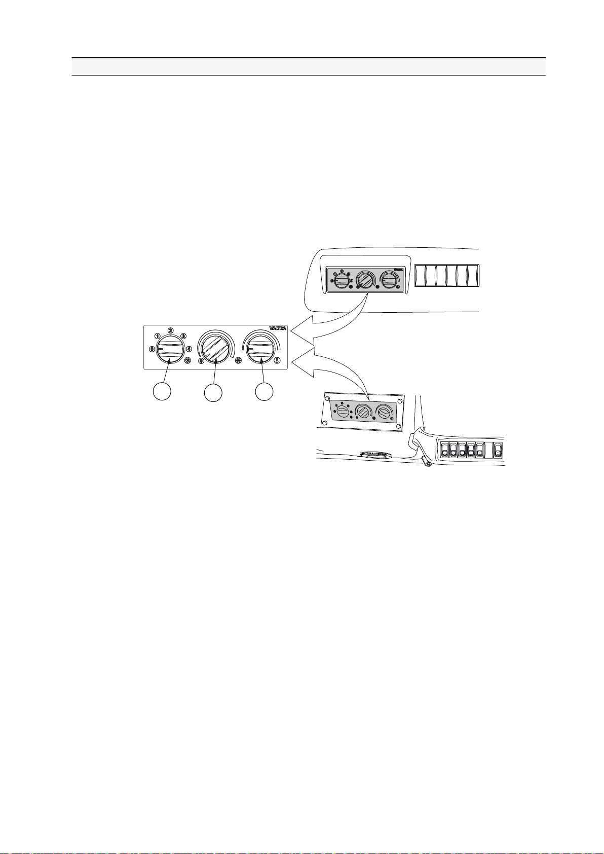
3.6.3 Using the manual air conditioning
1
2
3
The manual air conditioning system is extra equipment.
IMPORTANT: Use the air conditioning regularly to prevent seizing of the
compressor.
NOTE: Use the air conditioning for a few minutes at least once a month.
NOTE: When the air conditioning system is in use, the cab doors and windows
must be closed.
3. Operation
GUID-36336747-9DCD-4DD2-A039-04A5EE6EB22F
1. Fan control knob
2. Air conditioning control knob
3. Temperature control knob
1. Turn the temperature control knob anticlockwise to the extreme position.
2. When the engine is running, turn the air conditioning control knob clockwise
towards cold to the extreme position.
3. Turn the fan control knob to position 4.
4. When the desired cab temperature has been reached, adjust the air
conditioning control knob to maintain a comfortable temperature.
- 79 -
Page 81

1
1 2 3
4 5
6
3. Operation
5. Reduce the fan speed to obtain a comfortable temperature.
NOTE: To increase the efficiency of the air conditioning, keep the air
recirculation open.
GUID-302B33B9-04F4-44FF-B2DE-D6416FA987A7
1. Recirculation control lever
3.6.4 Automatic air conditioning
3.6.4.1 Air conditioning control panel
The automatic air conditioning system is extra equipment.
The control panel backlighting is white in daytime and green in the dark.
The graduation marks of the temperature control knob are always lit in blue or
red. The air conditioning on/off button and the defrosting button have an amber
indicator LED. The LED is lit only when the function is active.
GUID-8EEFE0E5-2C8D-4CE0-BA9D-FE61034A548D
1. Fan control knob
2. Display
3. Temperature control knob
4. Air conditioning system on/off button
5. Defrosting button
6. Recirculation control button
The operating temperature is -40°C...+80°C. The display decelerates in -30°C
and degrades in -40°C.
- 80 -
Page 82

3. Operation
3.6.4.2 Activating air conditioning when the battery has been disconnected
When the battery has been disconnected, you must calibrate the air conditioning
system.
• Turn the fan control knob to AUTO position.
The automatic air conditioning starts the calibration.
NOTE: During calibration, the air conditioning system cannot be used.
3.6.4.3 Air conditioning control
Different air conditioning control situations are described in the following.
Starting
When you start the tractor, the air conditioning automatically defaults to the last
selected adjustment, apart from the defrosting.
Temporary start mode
When you start the tractor in freezing weather, the air conditioning stays in the
starting mode until the temperature of the engine coolant reaches the preset value.
During the starting mode:
• The fan speed is at the minimum.
• The fresh air intake is on.
The starting mode ends when the engine coolant has reached the preset value or
if:
• The defrosting is connected.
• The LO setting mode is connected.
• A different speed is selected for the fan manually.
Priority of functions
The function with a higher priority controls the operations. The priority order of the
functions is as follows.
Defrosting
OFF mode .
Compressor, recirculation, fan speed .
HI setting mode, LO setting mode Low priority
For example, if you have selected the OFF mode with the fan control knob, the
defrosting function cancels the OFF mode and activates the defrosting functions.
High priority
IMPORTANT: Use the air conditioning regularly to prevent seizing of the
compressor.
NOTE: Use the air conditioning for a few minutes at least once a month.
You can activate the air conditioning using the air conditioning system on/off
button also in cold weather.
- 81 -
Page 83
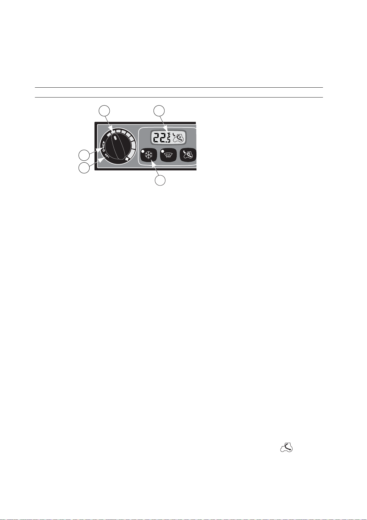
1 2
3
4
5
3. Operation
ECO mode
Switching off the air conditioning with the air conditioning system on/off button
activates the ECO mode. The air cooling compressor is turned off and the system
tries to achieve the target temperature by other available means, such as fresh
air intake and fan speed.
3.6.4.4 Controlling the fan
GUID-10CA7AA6-0D35-400C-8844-C7ACAF2351BC
1. Fan control knob
2. Display
3. AUTO position
4. OFF position
5. Air conditioning system on/off button
• Activate the air conditioning system to increase the fan speed by pressing the
air conditioning system on/off button.
The efficiency of the fan speed can vary when the system tries to maintain
the adjusted cab temperature. An increase in the sun heat radiation
increases the fan speed.
• Activate the automatic fan speed mode.
• To activate the automatic mode, turn the fan control knob to the AUTO
position.
• To activate the ECO mode, press the air conditioning system on/off
button when the fan control knob is in the AUTO mode.
If the selected cab temperature is lower than the outdoor temperature, the
numerical value of the temperature flashes on the display.
The fan speed changes gradually.
• Adjust the fan speed manually.
To change the fan speed from the default value of the AUTO position, turn
the fan control knob to the desired position.
The fan speed changes immediately.
• To deactivate the air conditioning system, turn the fan control knob to the
OFF position.
• The fan turns off.
• The recirculation of the indoor air is on, as indicated by the
on the display.
symbol
- 82 -
Page 84
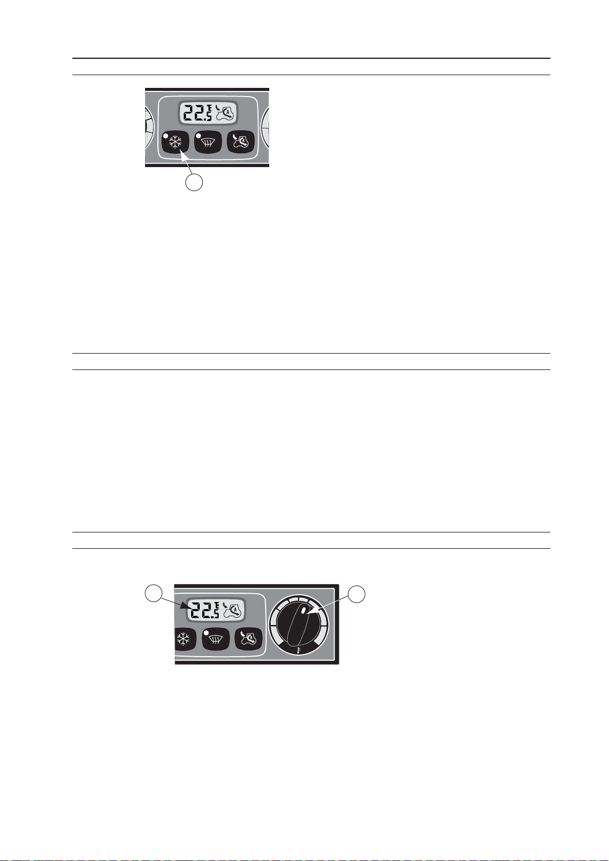
3.6.4.5 Automatic air conditioning system on/off button
1
1
2
GUID-D5681DD7-43B5-446A-8201-86C087D10D1D
1. Automatic air conditioning system on/off button
• When the automatic air conditioning is on, the amber indicator LED is lit.
• When the automatic air conditioning is off, the compressor and the indicator
LED are off.
• When the indoor-air recirculation is activated, the automatic air conditioning
is normally on. Switching off the air conditioning by pressing the automatic air
conditioning system on/off button turns off the compressor and activates the
ECO mode.
3. Operation
3.6.4.6 Temperature view
The selected temperature is displayed on the display.
• Within the range of 20-24°C, the temperature is displayed with an accuracy
of 0.5°C.
• Outside the range of 20–24°C, the temperature is displayed with an accuracy
of 1°C.
• If adjusted below 18°C, LO is displayed.
• If adjusted over 28°C, HI is displayed.
When the recirculation of the indoor air is active, the display shows HI, LO or the
tractor symbol depending on the situation.
3.6.4.7 Temperature control
You can adjust the cab temperature with the temperature control knob.
GUID-2E45CB01-D5C2-46B9-8BE2-20E32B3D338D
1. Display
2. Temperature control knob
Adjust the cab temperature with the temperature control knob. The selected
target temperature is shown on the display. Note that the selected temperature is
a target value that may not be reached in extreme cold/heat conditions.
- 83 -
Page 85
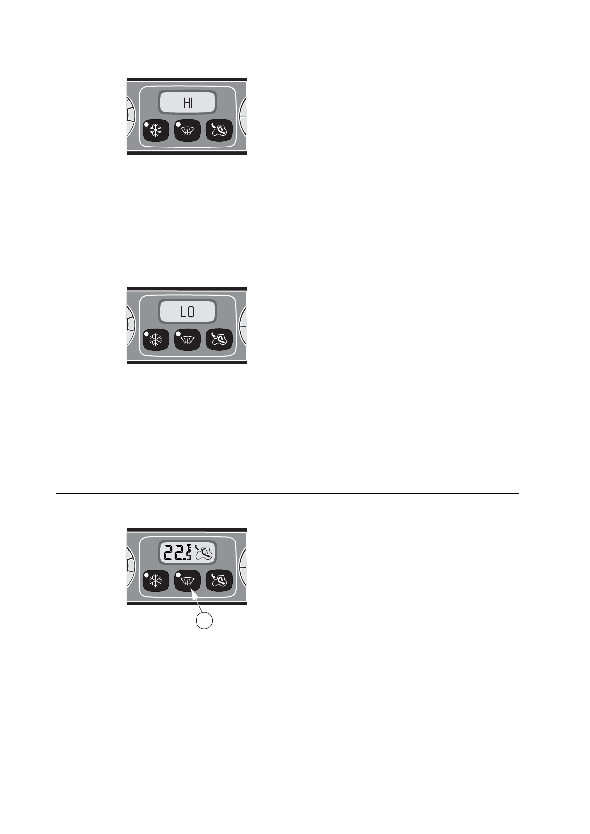
1
3. Operation
Setting mode HI
GUID-7D8E86DD-57B8-4BE1-B0BE-51E4FBF8BBAD
The maximum heating effect is reached by setting the cab temperature above
+28°C. When the HI mode is active:
• The air conditioning indicator LED is lit.
• The fan speed is 75% of the maximum (if operating automatically).
• The recirculation of the indoor air is off.
• The text HI is displayed.
Setting mode LO
GUID-56389D9F-BD9D-4DEF-96F7-0413544B75CF
The maximum cooling effect is reached by setting the cab temperature below
+18°C. When the LO mode is active:
• The air conditioning indicator LED is lit.
• The fan speed is at the maximum (if operating automatically).
• The recirculation of the indoor air is on.
• The text LO is displayed.
3.6.4.8 Defrosting
You can activate defrosting with the defrosting button.
GUID-17536714-B907-4F15-8F76-BA95846D2122
1. Defrosting button
The maximum time of continuous defrosting is three minutes. When the
defrosting is active:
- 84 -
Page 86
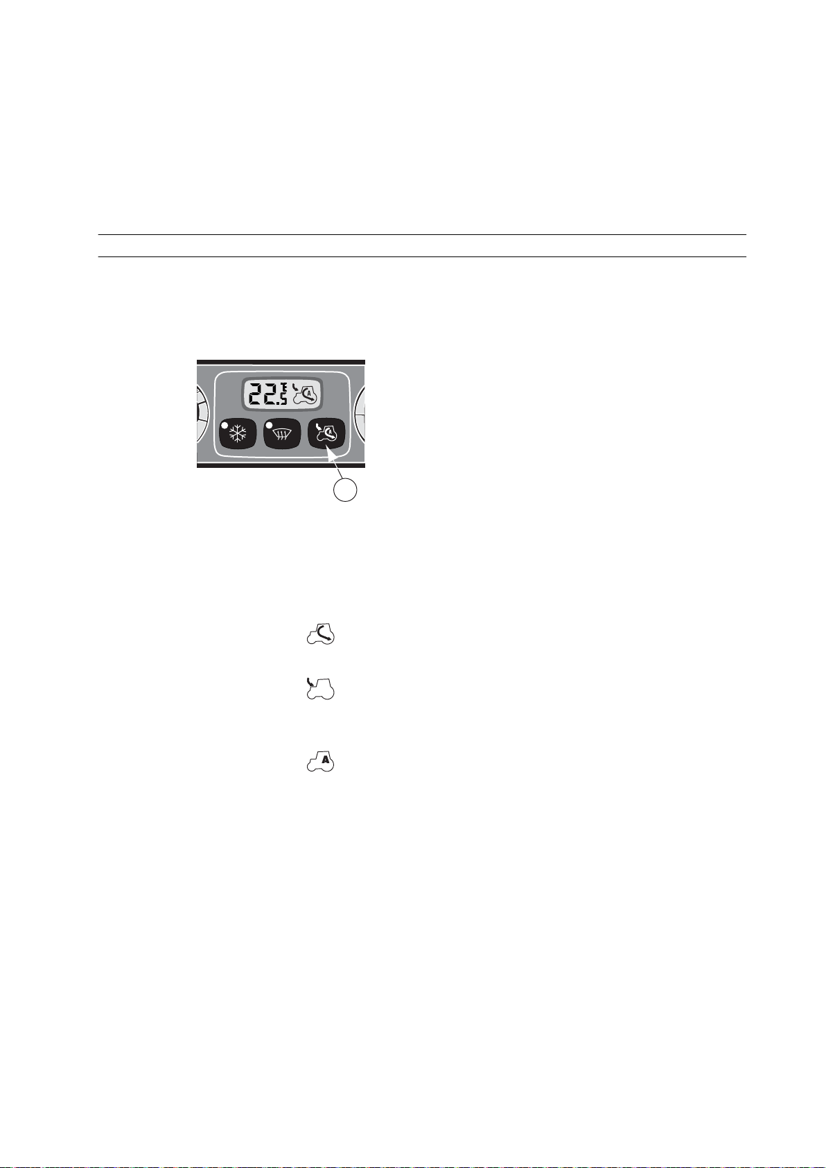
• The air conditioning indicator LED is lit.
1
• The defrosting button indicator LED is lit.
• The fan speed is 75% of the maximum.
• The fresh air intake is active.
• The text HI is displayed.
You can deactivate the defrosting by pressing the defrosting button again. The
former display mode is restored and the defrosting button indicator LED goes off.
3.6.4.9 Selecting air recirculation
You can select between fresh air intake, recirculation of indoor air, or the
automatic recirculation. With the automatic recirculation, the selection between
fresh air intake and indoor air recirculation is done automatically based on the
outdoor temperature.
3. Operation
GUID-C41534B7-AF68-47EC-AFE3-A1EDDE31F1DC
1. Recirculation control button
1. To switch on the cab indoor air recirculation, press the recirculation control
button once.
The symbol
is displayed.
2. Press the recirculation control button again to switch to the fresh air intake.
The symbol
is displayed.
3. Press the recirculation control button for the third time to switch to the
automatic recirculation.
The symbol
is displayed.
NOTE: When the air conditioning system is restarted, you have to wait two
minutes to ventilate the cab before activating the recirculation again.
After 25 minutes of continuous use, the system deactivates the air recirculation
for one minute.
It is recommended to use the fresh air intake with high outdoor temperatures.
Fresh air intake is automatically set if the automatic function is selected.
- 85 -
Page 87
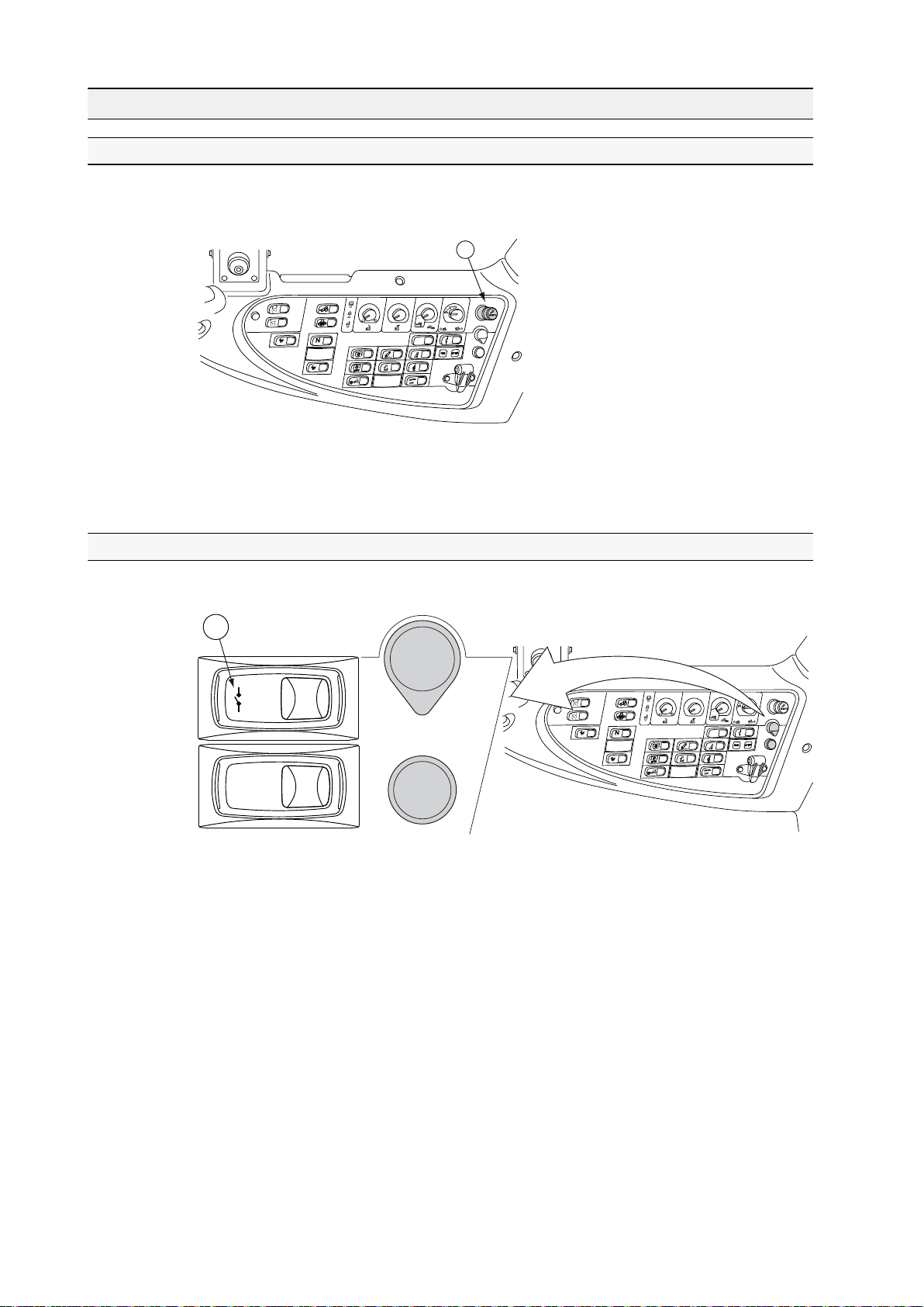
1
A
U
T
O
A
U
T
O
MIN
MAX
P
1
A
U
T
O
A
U
T
O
MIN
MAX
P
3. Operation
3.7 Power outlets
3.7.1 Lighter
The tractor is equipped with a lighter. The lighter socket can be used also as an
electric power output.
GUID-68D24224-6BDB-4D01-9EA1-A16EC6FDB766
1. Lighter
The lighter socket provides an output of 12 V DC; 10 A at a maximum.
3.7.2 Using the two-pin power socket and power switch
Use the two-pin power socket for electrical equipment.
GUID-8D929E77-A3DA-4F13-8164-59B1EA81885A
1. Power switch
The socket provides an output of 12 V DC; 8 A at a maximum.
The power switch controls the power socket next to it.
• To activate the power socket, press down the symbol side of the switch
(spring returned).
The light on the switch is lit.
• To disconnect the upper power socket, press down the side of the upper
switch opposite to the symbol.
The light on the switch goes out.
- 86 -
Page 88

3.7.3 Three-pin power socket
2
3 4
1
A
U
T
O
A
U
T
O
M
I
N
M
A
X
P
GUID-2E069E18-F87A-4955-886F-E29F9D45A466
1. Three-pin power socket
2. 5 A
3. 25 A
4. Ground
The direct current is supplied through the power socket for different regulating
elements, implements etc. 5 A is available through the ignition switch and 25 A
direct from the battery. The current supply of the 25 A pin can be switched off
with the main switch.
3. Operation
- 87 -
Page 89
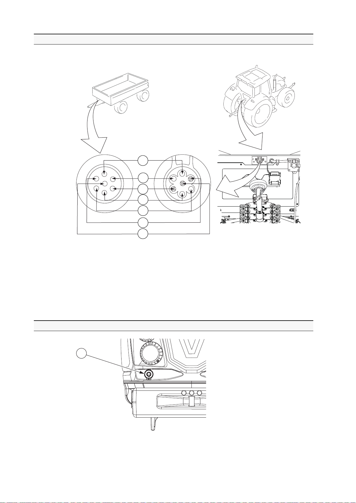
3
4
5
6
1
2
7
1
3. Operation
3.7.4 Trailer socket
Current from the tractor to the trailer is supplied through the trailer socket.
GUID-148BC744-BF50-4F98-8A87-331CC78ED56D
1. Direction indicator left (yellow)
2. Brake light (red)
3. Parking light right (brown)
4. Direction indicator right (green)
5. Ground (white)
6. Ignition switch current, max. 10 A (blue)
7. Parking light left (black)
3.7.5 Two-pin power socket on the bonnet
GUID-A5B54E44-9063-4602-9513-DA7B2A615CAE
1. Two-pin power socket
- 88 -
Page 90

The socket provides an output of 12 V DC; 10 A at a maximum. The power
socket is activated when the parking lights are on.
3.8 Driving the tractor
3.8.1 Steering
NOTE: When the engine is not running, the steering is not power assisted.
CAUTION: If a malfunction occurs in the steering system, stop the
tractor and correct the malfunction before restarting.
3.8.2 Power shuttle
You can change the driving direction smoothly with the power shuttle lever. The
engagement of the power shuttle is automatic.
You can request a driving direction change with the power shuttle lever at any
driving speed, but the transmission starts to engage the new driving direction only
when the speed is below 10 km/h. If the driving speed is higher, the transmission
does not automatically start braking until the speed is low enough.The new
direction arrow starts to flash to indicate that the driving direction change has
been requested, and is lit constantly when the new direction is engaged. If you
return the power shuttle lever to the original direction when the driving speed is
still over 10 km/h, the traction engages immediately.
3. Operation
When driving with automatic or semiautomatic driving mode, the tractor does not
move unless you press the driving pedal.
The operator detector prevents the shuttle engagement if you are not on the seat.
If the direction is selected, the arrow of the selected direction flashes on the
display panel. The selected direction does not engage until you sit on the seat
and move the power shuttle lever to the parking brake position (P) and then to
the desired direction.
• When the driving speed is below 5 km/h:
If you leave the seat for more than two seconds and the clutch pedal is not
pressed down more than 10%, the shuttle disengages and the direction
arrow flashes. The direction stays selected but the tractor does not move
until you sit on the seat and move the power shuttle lever to the parking
brake position (P) and then to the desired direction.
• When the driving speed is over 5 km/h:
If you leave the seat, the shuttle stays engaged.
DANGER: Do not leave the seat when the tractor is moving.
- 89 -
Page 91

1
3. Operation
3.8.3 Using the power shuttle lever
GUID-85975454-7178-48B4-A4A3-344CB5D07905
1. Power shuttle lever
• F (front position) = forward driving direction
• N (centre position) = neutral
• R (rear position) = reverse driving direction
• P = parking brake position
• Disengage or engage the parking brake.
• To disengage the parking brake, pull out the collar round the power
shuttle lever and move the power shuttle lever to the neutral (N) position.
• To engage the parking brake, pull out the collar round the power shuttle
lever and move the power shuttle lever to the parking brake (P) position.
In some situations (for example, after working with a heavy load) when
you engage the parking brake, the engine may perform cooling of the aftertreatment system by increasing the idling RPM momentarily. The word
COOL flashes on the A-pillar display.
IMPORTANT: Do not stop the engine when the idling RPM is increased.
Stopping the engine may damage the after-treatment system.
• Select the desired driving direction.
Move the power shuttle lever to the forward (F) or reverse (R) driving
direction. Change the driving direction at lower driving speeds with high load
so that there is less stress on the power transmission.
When driving with automatic or semiautomatic driving mode, the tractor does
not move before you press the driving pedal.
• Use the standstill function.
• To activate the standstill function, lift the power shuttle lever slightly
upwards from its current position.
• To continue driving after standstill, let the power shuttle back down.
When driving with automatic or semiautomatic driving mode, the tractor
does not move before you press the driving pedal.
- 90 -
Page 92

3.8.4 Adjusting the power shuttle engagement speed
D
D
You can adjust the power shuttle engagement speed through the tractor terminal
transmission settings.
The index determines how quickly the torque of the power shuttle increases to
the maximum value when the clutch is engaged. The index affects both the F
(forward) and R (rearward) clutch engagements. The value ranges from 1–10,
where:
• 1 = very slow engagement
• 10 = very quick engagement
1. Stop the engine and turn the ignition switch off.
2. Engage the parking brake.
3. Press the pre-programming push button, depress the clutch pedal and turn
the ignition on at the same time.
The setting menu symbols (D) appears on the display. The first two bars are
lit to indicate that the parameter number is shown on the bottom row.
3. Operation
4. Press the Powershift push buttons to select the parameter to be changed.
GUID-28D5159D-C9B9-404C-850F-29935043418E
The parameter number for power shuttle engagement speed is 0030.
- 91 -
Page 93

D
D
3. Operation
5. Press the Powershift pre-programming button.
The last two bars are lit to indicate that the parameter value is shown on the
bottom row.
6. Press Powershift push buttons to change the parameter value.
7. Press the Powershift pre-programming button to save the parameter value.
You can discard the changes by pressing the HiShift push button.
8. Press the HiShift push button exit the setting menu and save all changes.
If you want to leave the setting menu and discard all changes made, turn the
ignition switch off.
3.8.5 Using the parking brake
You can use the parking brake by changing the position of the power shuttle lever.
CAUTION: Do not use the parking brake when driving because it locks
all the wheels. The parking brake engagement speed is limited to 2 km/
h.
WARNING: Always apply the parking brake when parking the tractor.
WARNING: Before entering between the tractor and the implement,
prevent the tractor from moving by applying the parking brake or
blocking the wheels. There is risk of accidents if the tractor or
implement should move.
WARNING: The STOP indicator light starts flashing if the parking
brake cable breaks or the adjustment is wrong. Repair the fault or
adjust the cable before continuing driving.
- 92 -
Page 94

3. Operation
WARNING: The parking brake does not engage at driving speeds over
2 km/h. If you move the power shuttle lever to the P position at higher
driving speeds, the parking brake indicator light
on the instrument
panel and the P symbols on the A-pillar display flash and the buzzer
alarms intermittently until the speed drops below the limitAlways
ensure that the parking brake is actually engaged before leaving the
tractor.
WARNING: In turbine clutch models, always apply the parking brake
or block the wheels when parking. The transmission in these models
does not brake.
1. Stop the tractor completely.
2. Pull up the collar round the power shuttle lever, and move the lever to the
parking brake (P) position.
GUID-28B1703E-60BB-469D-AB73-6C9211A740A7
In some situations (for example, after working with a heavy load) when you
engage the parking brake, the engine may perform cooling of the aftertreatment system by increasing the idling RPM momentarily. The word COOL
flashes on the A-pillar display.
IMPORTANT: Do not stop the engine when the idling RPM is increased.
Stopping the engine may damage the after-treatment system.
When the parking brake is on, four-wheel drive (4WD) is engaged and all
wheels brake.
3. To release the parking brake, pull up the collar, and move the power shuttle
lever away from the parking brake (P) position.
- 93 -
Page 95

1
3. Operation
3.8.6 Using the clutch pedal
GUID-0FDC0EEE-E513-40D2-B148-7C426A433C57
1. Clutch pedal
1. Press the clutch pedal to release the traction.
2. Let the clutch pedal up gradually.
IMPORTANT: Never rest your foot on the clutch pedal while driving.
IMPORTANT: Do not allow the clutch to slip more than necessary when
moving off.
WARNING: Do not descend slopes with the clutch pedal pressed down.
WARNING: In turbine clutch models, always apply the parking brake
or block the wheels when parking. The transmission in these models
does not brake.
3.8.7 Adjusting the clutch pedal engagement position
You can adjust the clutch pedal's engagement position and clutch slipping
properties according to your preferences through the A-pillar display settings.
The index determines how quickly the clutch engages when the clutch pedal is
raised. The value range is between 1…4.
• 1 = the clutch engages quickly, the engagement point is relatively low.
• 4 = the clutch engages slowly, the engagement point is relatively high.
1. Stop the engine and turn the ignition switch off.
2. Engage the parking brake.
- 94 -
Page 96
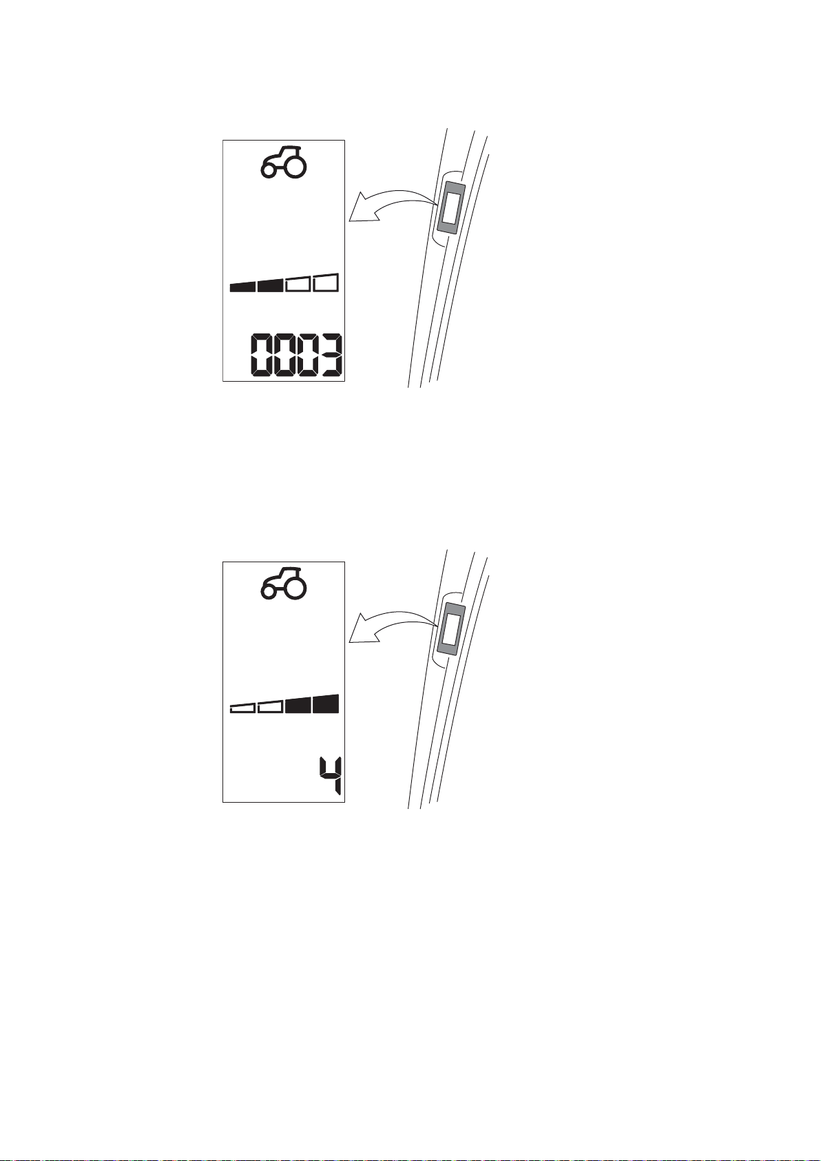
D
D
D
D
3. Operation
3. Press the pre-programming push button, depress the clutch pedal and turn
the ignition on at the same time.
GUID-A50D523E-B207-4B9A-A6C0-5A2F20FFB750
The setting menu symbols (D) appears on the display. The first two bars are
lit to indicate that the parameter number is shown on the bottom row.
4. Press the Powershift push buttons to select the parameter to be changed.
The parameter number for clutch pedal engagement position is 0003.
5. Press the Powershift pre-programming button.
GUID-64F3E289-A1E4-4E05-821F-FD93CEE3FE28
The last two bars are lit to indicate that the parameter value is shown on the
bottom row.
6. Change the parameter value by pressing Powershift push buttons.
7. Press the Powershift pre-programming button to save the value.
You can discard the changes by pressing the HiShift push button.
8. Press the HiShift push button to leave the setting menu and save all changes.
If you want to leave the setting menu and discard all changes made, turn the
ignition switch off.
- 95 -
Page 97
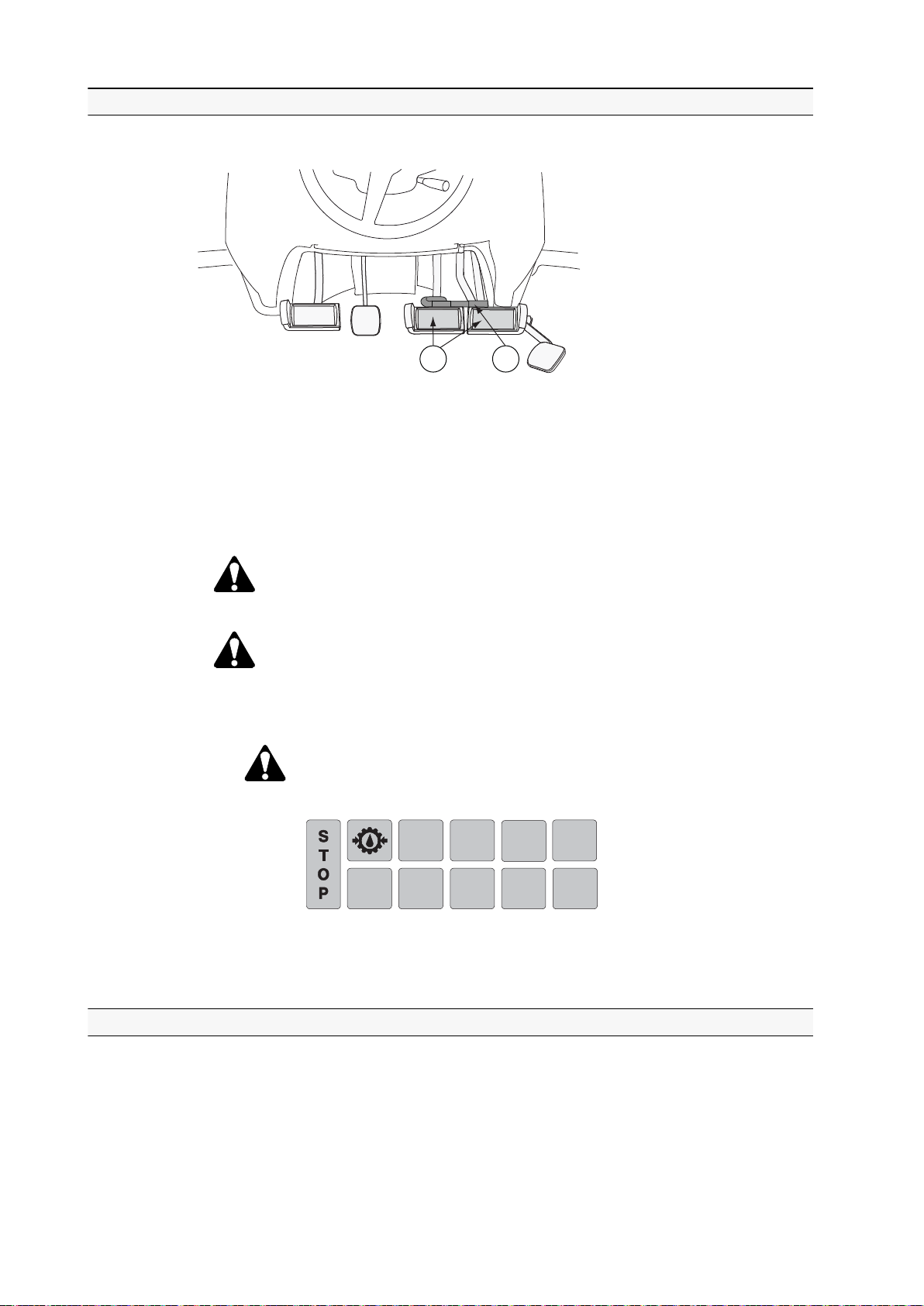
1
2
3. Operation
3.8.8 Braking
You can use the brake pedals differently in various working situations.
GUID-6295F787-9808-4BE4-BDB6-EA7943B8DF78
1. Brake pedals
2. Latch for brake pedals
The tractor has two brake pedals which apply separately to the right and to the
left side rear wheels. All four wheels are braking when pressing both brake
pedals. The pedals can be locked together with a latch to brake evenly with all
four wheels.
WARNING: The brake pedals must always be latched together when
driving on the road.
CAUTION: If functional problems occur in the braking system, stop the
tractor and rectify the fault before continuing.
• To brake evenly with four wheels, press down the both brake pedals.
DANGER: The brake action is weaker if the gearbox oil pressure
warning light is lit and the STOP indicator light begins to flash.
Stop the tractor and correct the fault before continuing.
GUID-6E20D973-F8F1-45E7-A113-8532047A28F0
• To intensify steering by braking when turning on the field, press down the
brake pedal on the inner curve side.
3.8.9 Using the emergency brake
If the brakes fail while driving, you can control braking with the emergency brake
lever.
The emergency brake is extra equipment.
The emergency brake is applied to the rear wheels.
- 96 -
Page 98
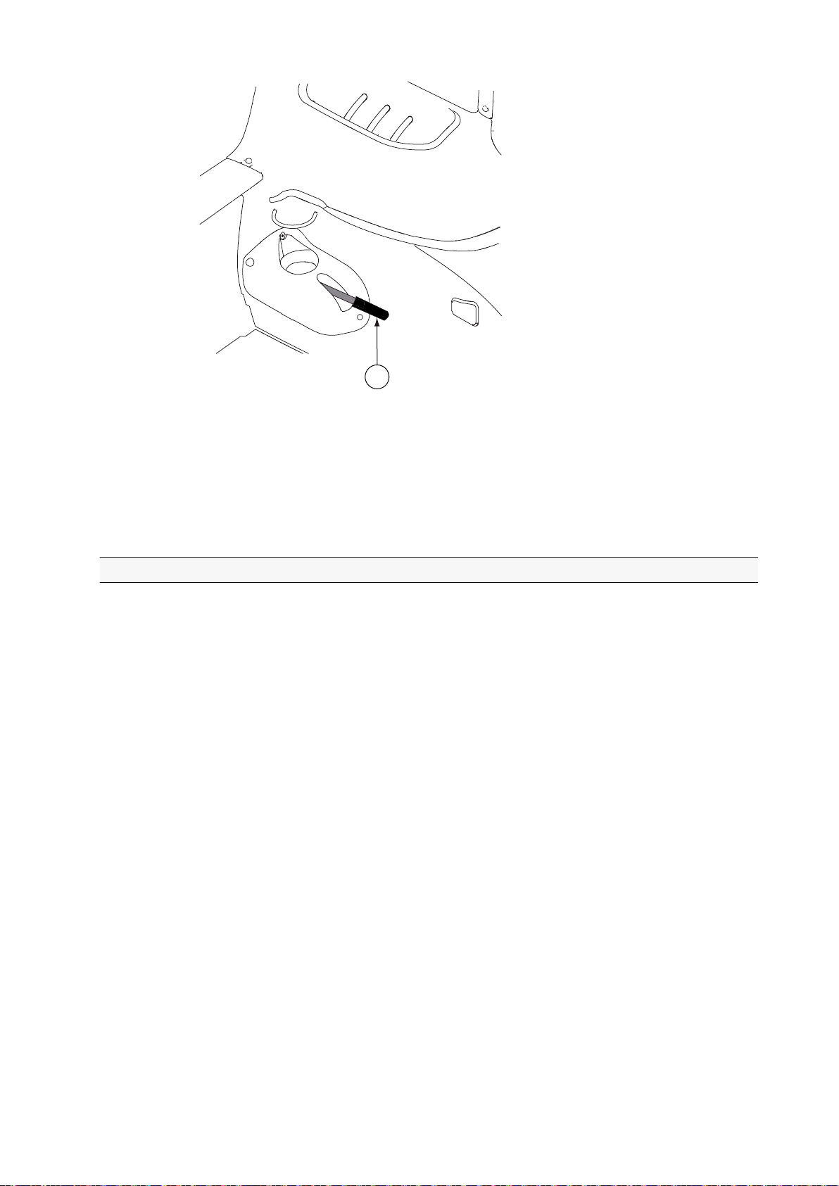
1
GUID-CEE3F5AE-C363-416E-8D95-B195A8527D24
1. Emergency brake lever
3. Operation
1. Pull up the emergency brake lever.
You have to pull it constantly as it does not stay locked.
2. Release the lever when the tractor has stopped.
3.8.10 Starting to drive
1. Start the engine.
2. Press down the brake pedals to keep the tractor stationary.
3. Select the speed range and Powershift.
Select a speed range which:
• gives the optimum fuel consumption without overloading the engine and
the transmission.
• allows the engine to operate comfortably at about 75% of its maximum
power.
IMPORTANT: Use the creeper gear for slow driving speeds only. Do not use
it for bigger drafting force.
4. Select the speed gear.
5. Move the power shuttle lever either to drive forward or reverse.
6. Release the brake pedals.
7. Adjust the driving speed with the accelerator pedal or the hand throttle.
Keep an eye on the indicator lights and gauges while driving.
- 97 -
Page 99

3. Operation
WARNING: Do not turn the ignition key to the STOP position when
driving. When the power is off, the parking brake applies and all
wheels lock.
NOTE: If the engine stops when driving, for example due to overload, you must
turn the ignition key to the STOP position before starting again.
3.8.11 Transmission system
The tractor transmission system has four speed gears and three range gears. In
addition, the tractors have 3–step quick-shift gear. These together give the tractor
36 forward and 36 reverse gears.
The range gears are named LL, M and H. The range gear LL is called creeper
range gear. The actual driving speeds achieved depend on the engine speed and
the tyres. The following table includes approximate driving speeds for each speed
range with engine speed of 1400–2200 rpm.
40 km/h models
Speed range
LL1 0.4 – 1.0 km/h
LL2 0.6 – 1.4 km/h
LL3 0.8 – 2.0 km/h
LL4 1.5 – 2.9 km/h
M1 2.0 – 4.9 km/h
M2 2.9 – 7.0 km/h
M3 4.0 – 9.8 km/h
M4 5.3 – 13.8 km/h
H1 6.3 – 15.2 km/h
H2 9.0 – 21.7 km/h
H3 12.6 – 30.5 km/h
H4 17.9 – 43 km/h
Driving speed
50 km/h models
Speed range
LL1 0.5 – 1.2 km/h
LL2 0.7 – 1.8 km/h
LL3 1.0 – 2.5 km/h
LL4 1.4 – 3.5 km/h
M1 2.5 – 6.1 km/h
M2 3.6 – 8.7 km/h
M3 5.0 – 12.3 km/h
M4 7.1 – 17.4 km/h
H1 7.9 – 19.1 km/h
H2 11.3 – 27.3 km/h
H3 15.9 – 38.3 km/h
H4 22.4 – 53 km/h
Driving speed
- 98 -
Page 100

3.8.11.1 Speed matching
1
2
AUTO
AUTO
M
I
N
M
A
X
P
The speed matching automatically tries to even out speed differences which are
too high by engaging the appropriate Powershift gear.
Speed matching is always on when the driving speed is over 0.5 km/h and:
• When changing speed range.
or
• When the shifting automatics is in use and the power shuttle lever is in the
centre position (N) or the HiShift push buttons are pressed down or the clutch
pedal is pressed down.
3.8.11.2 Selecting the range gear
3. Operation
GUID-330A651B-D189-41E3-AAE5-38FAAABD8945
1. HiShift push button
2. Range gear lever
NOTE: Use the speed gear lever, not the range gear lever, to set the
transmission to neutral when the engine is running.
1. Press down the clutch pedal or the HiShift push button.
2. Choose the wanted range gear with the range gear lever.
When engaging the creeper range (LL) the tractor must be stationary.
IMPORTANT: Use the creeper gear for slow driving speeds only. Do not use
it for bigger drafting force.
3. Release the clutch pedal or the HiShift push button.
- 99 -
 Loading...