


VALTRA – VALMET MEGA MEZZO HI-TEC
WORKSHOP MANUAL

6000, 6100, 6200 6250, 6300, 6350 6400, 6550, 6600 6650, 6800, 6850 6900, 8000, 8100 8200, 8400, 8050 8150, 8450, 8550 8750, 8950 6600E---8750E
Service Manual
Tractors
Groups 10---100
Valtra Inc.
44200 Suolahti, Finland
10 General
20 Engine
30 Electrical
system
40 Power
transmission
50 Brakesystem
60 Steering system and Front axle
70 Frame and
Wheels
80 Cab and
Shields
 90 Hydraulics
 100 Tools
Order no 39 210 211 ENGLISH

10. General
11.Layout
12.Repairs
13.Maintenance
2
To the reader
The Service Manual for the Valmet tractors is intended to be a practical reference source to be used in workshop. The repair instructions in the manual are based on methods which have been worked out in practice during normal workshop conditions and which are based on the use of special tools from the manufacturer when stated in the instructions. The manual also contains descriptions of the design and function of the components.
Detailed maintenance instructions can be found in Operator’s Manual.
The Service Manual will be continually updated with new revised pages which should be inserted in the manual. Alterations and additions will first appear as service bulletins.
Only genuine Valmet spare parts should be used to ensure the best possible function of the machine. Certain operations should be carried out with the aid of special tools designed by Valmet.
Valmet Tractors Inc.
Tractor Service
3
4

|
|
|
1. 8. 2000 |
Model |
Code |
Page |
||
11. General |
|
|
|
|
|
|
||
|
|
1. 9. 2002 |
|
6000--8950 |
110 |
0 |
||
|
|
|
|
|
|
|
||
The following supplements have been published for the Valmet 6000---8950 Service Manual: |
|
|
|
|||||
|
|
|
|
|
|
|
||
Ordering number |
Date |
|
Notes |
|
|
|
||
|
|
|
|
|
|
|
|
|
39 256 211 |
15. 6. |
1992 |
|
|
|
|
|
|
39 256 212 |
1. |
9. 1992 |
|
|
|
|
|
|
39 256 213 |
15. 5. |
1993 |
|
|
|
|
|
|
39 256 214 |
1. |
1. 1994 |
|
|
|
|
|
|
39 256 215 |
1. |
1. 1995 |
|
|
|
|
|
|
39 256 216 |
15. 4. |
1995 |
|
|
|
|
|
|
39 256 217 |
15. 5. |
1996 |
|
|
|
|
|
|
39 256 218 |
1. |
4. 1997 |
|
|
|
|
|
|
39 256 219 |
1. |
8. 1998 |
|
|
|
|
|
|
39 260 211 |
1. |
11. |
1998 |
|
|
|
|
|
39 260 212 |
1. |
6. 1999 |
|
|
|
|
|
|
39 260 213 |
1. |
10. |
1999 |
|
|
|
|
|
39 260 214 |
1. |
8. 2000 |
|
|
|
|
|
|
39 260 215 |
1. |
9. 2002 |
|
|
|
|
|
|
|
|
|
|
|
|
|
|
|
Supplement no. 39 256 211 (15. 6. 1992) |
--- Hi Shift |
|
Includes: |
||
--- Autocontrol III |
--- amendments |
|
--- air conditioning |
--- the latest fitting instructions of optional equipment |
|
--- tractor 8000 |
Supplement no. 39 256 219 (1. 8. 1998) |
|
--- amendments |
||
Supplement no. 39 256 212 (1. 9. 1992) |
Includes: |
|
--- FieldMaster |
||
Includes: |
--- pressure air brakes for trailer (optional) |
|
--- 20---series engines |
--- latest fitting instructions for optional equipment |
|
--- amendments |
--- amendments |
|
Supplement no. 39 256 213 (15. 5. 1993) |
--- new folder, new index leaves (10---30 and 40---100) and new |
|
spine labels. |
||
Includes: |
Supplement no. 39 260 211 (1. 11. 1998) |
|
--- Delta Powershift |
||
--- tractor 8400 |
Includes: |
|
--- amendments |
--- HiTech reverse shuttle |
|
--- the latest fitting instructions of optional equipment |
--- Autocontrol V |
|
|
--- New 50---series models |
|
Supplement no. 39 256 214 (1. 1. 1994) |
--- Front axle air suspension |
|
--- E---engines |
||
Includes: |
--- Amendments |
|
--- tractors 6000 and 8200 |
Supplement no. 39 260 212 (1. 6. 1999) |
|
--- Autocontrol II |
||
--- Autocontrol IV |
Includes: |
|
--- Sige---axle differential lock |
--- Autocontrol 2.2 |
|
--- industrial front axle |
--- amendments (e.g. for AC V) |
|
--- latest air conditioning |
--- fitting instructions for optional equipment |
|
--- amendments |
Supplement no. 39 260 213 (1. 10. 1999) |
|
Supplement no. 39 256 215 (1. 1. 1995) |
||
Includes: |
||
Includes: |
--- Carraro 20.29 front axle |
|
--- amendments |
--- amendments (e.g. version 42 of AC V) |
|
--- the latest fitting instructions of optional equipment |
Supplement no. 39 260 214 (1. 8. 2000) |
|
Supplement no. 39 256 216 (15. 4. 1995) |
||
Includes: |
||
Includes: |
--- HiTech gen. 2, AC---5.2 |
|
--- engine intake air system and cooling system, modifications |
--- front PTO on 6250H---6850Hi tractors |
|
--- Autocontrol 2.1 |
--- modified lubricating oil pump for 6---cyl. engines |
|
--- Agrodata---instrument |
--- new rear axle housing for transmissions 650/550 |
|
--- hydraulic type clutch release mechanism |
--- amendments |
|
--- DPS, modifications |
--- updated fitting instructions for optional equipment |
|
Supplement no. 39 256 217 (15. 5. 1996) |
Supplement no. 39 260 215 (1. 9. 2002) |
|
Includes: |
Includes: |
|
--- tractor 6800 |
--- transmission and final drives 700 |
|
--- tractors 8050---8750 |
--- Agroline---instrument |
|
--- amendments |
--- technical modifications |
Supplement no. 39 256 218 (1. 4. 1997)
Includes:
---tractors 6200 and 8000R
---front PTO
---CareTel
6

|
|
|
|
|
|
|
|
|
Model |
Code |
Page |
|
|
|
|
|
|
|
|
|
|
|
|||
|
|
|
|
|
|
|
|
|
|
|||
|
|
|
|
|
|
|
|
|
|
|||
|
|
|
|
|
|
|
|
|
|
|||
11. Layout |
8. 11. 1990 |
6000--8750 |
110 |
1 |
|
|||||||
|
|
|
|
|
|
|
|
|
|
|
|
|
|
|
|
|
|
|
|
|
|
|
|
|
|
Layout of Service Manual
1. Division into groups
The manual is divided into groups (10---100) which are based on the make---up of the tractor. The groups are listed on the first index leaf.
Example. |
10. |
General |
|
20. |
Engine, fuel and cooling systems |
|
30. |
Electrical system |
|
40. |
Power transmission |
a.s.o.
The number designation for each group is given in the top left box of the respective pages (and the first figure in the code designation)
Code Page
410 1
50
60
70
80
90
100
2. Division into components or sub---groups
Each group is further divided into components or sub---groups. The number and the name of each component is given in the top left box on each page (and comprise the two first figures in the code designation).
Example. 41. Clutch
42. Gearbox
44.Quick---shift gear
45.Final drives etc.
7
|
|
Model |
Code |
Page |
11. Layout |
8. 11. 1990 |
6000--8750 |
110 |
2 |
|
|
|
|
3. Code designation
Three---digit code designations are used to distinguish the different document groups for the respective components. The same code is also used in the Time List as a reference to the text in this Manual. The code designation numbers appear both in the box at the top of the page and also in the headings.
Example: Code 410:
--- Group: Power transmission (4)
--- Component: Clutch (41)
--- Document group: General (410)
4. Page numbers
The instructions for all components are numbered in consecutive order in the right---hand box at the top of the page. The page numbers begin with page 1 for each component.
|
|
|
|
|
|
|
|
|
|
|
|
|
|
|
Model |
Code |
Page |
|
41. Clutch |
8. 11. 1990 |
|
||||||||||||||||
15. 5. 1993 |
6100---8400 |
410 |
1 |
|
||||||||||||||
|
|
|
|
|
|
|
||||||||||||
|
|
|
|
|
|
|
|
|
|
|||||||||
5. Date
At the top of each page there are two boxes for dates. In the case of a revised issue, the date of the earlier issue is printed in the crossed---over box and the date of the current issue is printed in the ”real” date box.
6. Model
At the top of each page the tractor model for which the page is valid is indicated.
7. Additions and amendments of the service manual
New and up---dated pages will be continually added to the service manual. The new pages should be inserted as indicated by the code: the first digit (also the first digit on the index leaf) indicated the group:
---the two first digits indicate the component or sub---group
---the third digit indicates the document group for the respective components
---the page number indicates the definite position of the page within the service manual
If there are two pages with the same code and page number the page with the later date in the date box (and the old date in the crossed---over box) is valid (or the current page).
N.B. Fitting instructions for extra equipment are inserted into the service manual at the end of group concerned (E.g. code 39 is inserted at the end of group 30).
8

|
8. |
11. 1990 |
Model |
Code |
Page |
11. Layout |
|
|
|
||
1. |
4. 1997 |
6000--8750 |
110 |
3 |
|
|
|
|
|
Code designation in the Service Manual
10. General
110 Layout
120 Repairs
130 Maintenance
20 Engine
21. Engine
210 Technical data, tools, description
211 Cylinder block and flywheel housing
212 Cylinder head and valve mechanism
213 Crank mechanism
214 Timing gears
215 Lubrication system and oil sump
216 Induction and exhaust system, turbocharger
219 Removing and fitting engine
22. Fuel system
220 Technical data, tools, description
222 Fuel feed pump and fuel filters
223 Injection pump and injectors
23. Cooling system
230 Technical data, tools, description
231 Thermostat and coolant pump
30. Electrical system
310 Specifications, wiring diagrams
311 Autocontrol II
312 Autocontrol 2.1
313Sigma---power
320AC power lift
321ACD power lift
330Agrodata
331AD---instrument
340Autocontrol---III
350Autocontrol IV
360CareTel
40.Power transmission
41.Clutch
410 Technical data, tools, description
411 Clutch assembly and pedal rods
412 Hydraulic coupling
42. Gearbox
420 Technical data, tools, description
421 Selector forks
422 Gear shift levers
423 Shafts and gear wheels
424 Differential
44.Quick---shift gear, DPS, reverse shuttle, 4WD clutch
440A Quick---shift gear, technical data, tools, description
440B Reverse shuttle, technical data, tools, description
440C 4WD clutch, technical data, tools, description
441Quick---shift gear, repair instructions
442Reverse shuttle, repair instructions
4434WD clutch, repair instructions
444DPS, repair instructions
45.Final drives
450 Technical data, tools, description
451 Final drives, repair instructions
46 Power take---off
460 Technical data, tools, description
461 Power take---off, repair instructions
463 Front PTO, repair instructions
9

11.Layout
50.Brakes
510 Technical data, description
511.Service brakes
520Parking brake
60.Steering system and front axle
61.Steering system
610 Technical data, tools, description
611 Steering valve
612 Priority valve
613 Steering cylinder
614 Adjustment
64. Powered front axle
640 Technical data, tools, description
641 Front axle housing and front axle suspension
643Hubs
644Differential
645Industrial front axle
70 Frame and wheels
710 Tractor frame
720 Tyres and wheel discs
80 Cab and shields
810 Cab
820 Shields
830 Air conditioner
90 Hydraulics
910 Technical data, tools, description
911 Pump and pipes
912 Working hydraulics
913Three---point linkage, towing hook
920AC power lift
100.Special tools
101Special tools (ETV)
102Locally manufactured tools
8. 11. 1990 |
Model |
Code |
Page |
|
|
|
|
1. 4. 1997 |
6000--8750 |
110 |
4 |
|
|
|
Note! Separate fitting instructions for the optional equipments are inserted into the Service Manual. These instructions are positioned to the end of each main group. E.g. code 39 are placed to the end of group 30.
10

|
|
|
|
|
|
|
Model |
Code |
Page |
|
|
|
|
|
|
|
|||
|
|
|
|
|
|
|
|||
|
|
|
|
|
|
|
|||
12. Repairs |
8. 11. 1990 |
6000--8750 |
120 |
1 |
|||||
|
|
|
|
|
|
|
|
|
|
General instructions for repairs
Outer oil seals
The Service Manual contains instructions for changing all outer oil seals, (e.g. oil seals on the PTO shaft end, on the output shaft to the front wheel drive and on the pinion shaft on the powered front axle, and so on).
Sealing compound and glue
If sealing compounds or glue are required for the repair work, the instructions will specify a sealing compound or glue which is readily available through specialist dealers. Some seals should be greased before fitting and the space between the lips of the seal should be filled with universal grease. If the seal is to be pushed over splines or sharp edges the seal should be protected with for example a thin plastic foil.
Tightening torques and setting values
All necessary tightening torques and setting values for each repair operation are given at the beginning of each repair section under the heading Technical Data. The most important values can also be found in the repair instructions.
Table 1 later gives the tightening torques in order of dimension, quality and surface treatment. The values given in the table should be used if the tightening torque is not given in the repair instructions.
Safety
Always bear safety in mind when repairing or servicing the tractor. Use tools and lifting devices in the correct way . When you are removing tractor components or splitting the tractor, every tractor part must be supported in such a way, that no risk of accident exists. Avoid working under the supported tractor part if it is not absolutely necessary. When supporting the tractor the centre of gravity of the frame part must always be checked. For instance the wedges must always be fitted between front axle and engine to prevent axle oscillation when splitting the front frame of the tractor.
Trouble---shooting
The following procedure, combined with the information contained in the workshop manual will be helpful in tracing faults accurately. It consists of following a number of logical steps to locate and correct the problem:
a)Determine the problem
b)List possible causes
c)Differentiate the causes
d)Conduct checks in logical order to determine the exact cause
e)Consider approximate remaining service life against cost of parts and labour..
f)Make any necessary repairs.
g)Recheck the parts and functions for correct operation
11

12. Repairs
Handling of heavy components
Unless otherwise specified, all removals should be accomplished using adjustable lifting equipment. All supporting slings must be parallel to each other and as near vertical as possible in relation to the object being lifted. However, where slings are of a far greater capacity than the weight of the load to be fitted, a triangular lifting arrangement may be used.
Oikein |
Correct |
Väärin |
Mauvais |
Rätt |
Teisingai |
Fel |
Netei- |
Right |
|
Wrong |
singai |
Richtig |
|
Falsch |
|
Giusto |
|
Sbagliato |
|
When removing a component at an angle, remember that the capacity of an eyebolt is reduced when the angle between the supporting members and the object becomes less than 90˚.
B
C
D
A
Forged eyebolt support
A.Load
B.Lifting shackle
C.Shackle retaining plate ( 3 mm thick)
D.Sleeve
When necessary the forged eyebolt can be supported in the way shown in figure above. Sleeve D may or may not be welded to plate.
Warning! If a part resists removal, check that all nuts and bolts have been removed and that there is no interference from adjacent parts.
|
Model |
Code |
Page |
8. 11. 1990 |
6000--8750 |
120 |
2 |
|
|
|
Cleanliness
To ensure long life of a machine, it is important to keep dirt and
foreign material out of its vital working components. Precautions must be taken to safeguard against this. Enclosed compartments, seals and filters have been provided to keep the supply of air, fuel and lubricant clean. These protective devices must not be removed.
Whenever hydraulic, fuel, lubricating oil or lines are disconnected, clean the point of disconnection and the surrounding area. As soon as a line has been disconnected, cap, plug or tape the line or opening to prevent the ingress of foreign material.
The same cleaning and covering precautions should be taken when access covers or inspection plates are removed.
Clean and inspect all parts. Make sure that all passages and holes are clear. Cover all parts to keep them clean. Make sure parts are clean when they are reassembled. Leave new parts in their wrapping until they are actually needed for reassembly
Assembly
When reassembling a machine, complete each step in se-
quence. never partially assemble one part then start to assemble another. Make all recommended adjustments. Always check the job on completion to ensure that nothing has been overlooked. Recheck the various adjustments before putting the machine back into service.
Note! Before fitting new parts, remove rust preventative compound from all machined surfaces (usually ”peel---off substances).
Lubrication
Where applicable, fill the compartments of repaired or renewed components with the quantity, type and grade of clean lubricant recommended in the routine maintenance section of the Operator’s Manual.
Shims
When shims are removed, tie them together and identify their location. Keep shims clean and take care not to bend them before refitting them.
Gaskets
Make sure that the holes in gaskets line up with lubricating oil passages in the mating parts. If gaskets have to be made, use material of the correct type and thickness. Make sure that holes are punched in the right places.
Incorrectly punched gaskets can cause serious damage.
Lip type rubber seals
Lubricate the lips of lip---type rubber seals with oil before fitment. Do not use grease on seals, except for grease seals.
12
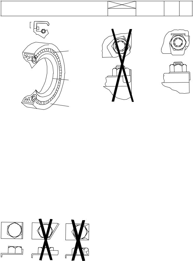
12. Repairs
4
 5
5
3
2
1
The main parts of lip---type seal:
1.Case
2.Sealing element
3.Ring spring
The figure above shows the construction of a simple lip---type seal. The cross section shows the heel (4) and the toe (5), used to identify the sides of a single element seal. With a few exceptions, the toe of a single---lip is located on the lubricant side. Some seals have a second auxiliary lip which has no spring.
Cables and wires
When removing or disconnecting a group of cables or wires, label each one to ensure correct refitment.
Locking devices
|
Model |
Code |
Page |
|
8. 11. 1990 |
6000--8750 |
120 |
3 |
|
|
|
|
|
|
|
|
|
|
|
|
|
|
|
|
Correct and incorrect method of fitting and bending locking tabs.
Slackening of nuts and bolts is prevented by mechanical means such as lockwashers, tab washers and cotter pins, or by Loctite---type locking agents.
Flat retainers must be installed properly to be effective. Bend one end of the retainer against the edge of the part. Bend the other end against one of the nut or bolt head.Always fit new retainers in compartments which house moving parts. When fitting lockwashers on aluminium housings, place a flat washer between the lockwasher and the housing.
Note!
1)Never fit a lockwasher (Grower, fan, spring, etc.) under a nut or bolt to which a specified torque has to be applied.
2)Always thoroughly degrease components before applying Loctite type locking agents.
|
Bushes and press fits |
|
Do not fit bushes with a hammer alone. Use a suitable fitting |
|
tool and a hammer or, better still, a press if possible.. |
|
When using a press, ensure that pressure is applied directly |
|
in line with the bore. If the ring has an oil hole, take care toalign |
|
it with the oil hole in the mating part. When press fitting a part |
|
into another part, lubricate the mating surfaces. Tapered parts |
|
should be assembled dry. Before assembly, check that the |
|
tapers are dry and free from burrs. |
|
Fitting bolts in blind holes |
Correct and incorrect use of retainers |
Use bolts of the correct length. A bolt which is too long may |
|
|
|
”bottom” before the head comes into contact with the part it |
|
is to hold: this will cause damage to the threads. If a bolt is too |
|
short, there may not be enough threads engaged to hold the |
|
part securely. |
13

|
|
Model |
Code |
Page |
12. Repairs |
8. 11. 1990 |
6000--8750 |
120 |
4 |
|
|
|
|
Table
Table 1. Tightening torques, metric standard thread (ISO)
|
Tightening torques Nm1) |
|
|
|
|
|
|
|
||
Dim. |
|
|
|
|
|
|
|
|
|
|
Quality, surface treatment, material and so on |
|
|
|
|
|
|||||
|
8.8 |
|
8.8 |
|
8.8 |
|
10.9 |
|
12.9 |
|
|
|
|
|
|
|
|||||
|
lubr. |
tol.± |
Zne2) |
tol± |
Znk3) |
tol. ± |
lubr. |
tol. ± |
lubr |
tol. ± |
M4 |
--- |
|
--- |
|
--- |
|
--- |
|
--- |
|
|
|
|
|
|
|
|
|
|
|
|
M5 |
6,4 |
0,6 |
5,7 |
0,5 |
--- |
|
9 |
1 |
11 |
1 |
|
|
|
|
|
|
|
|
|
|
|
M6 |
11 |
1 |
10 |
1 |
12 |
1,2 |
15 |
1,5 |
18 |
2 |
|
|
|
|
|
|
|
|
|
|
|
M8 |
25 |
2 |
23 |
2 |
30 |
3 |
35 |
4 |
45 |
5 |
|
|
|
|
|
|
|
|
|
|
|
M10 |
50 |
5 |
45 |
5 |
60 |
5 |
70 |
7 |
90 |
10 |
|
|
|
|
|
|
|
|
|
|
|
M12 |
90 |
10 |
80 |
8 |
100 |
10 |
125 |
10 |
151 |
15 |
|
|
|
|
|
|
|
|
|
|
|
M14 |
140 |
15 |
125 |
10 |
160 |
15 |
200 |
20 |
240 |
20 |
|
|
|
|
|
|
|
|
|
|
|
M16 |
220 |
20 |
195 |
20 |
250 |
25 |
300 |
30 |
370 |
40 |
|
|
|
|
|
|
|
|
|
|
|
M18 |
300 |
30 |
270 |
30 |
350 |
35 |
430 |
40 |
510 |
50 |
|
|
|
|
|
|
|
|
|
|
|
M20 |
430 |
40 |
380 |
40 |
480 |
50 |
600 |
60 |
720 |
70 |
|
|
|
|
|
|
|
|
|
|
|
M22 |
570 |
60 |
500 |
50 |
650 |
65 |
800 |
80 |
970 |
100 |
|
|
|
|
|
|
|
|
|
|
|
M24 |
740 |
70 |
660 |
70 |
830 |
80 |
1030 |
100 |
1250 |
120 |
|
|
|
|
|
|
|
|
|
|
|
M27 |
1100 |
100 |
950 |
100 |
1200 |
120 |
1500 |
150 |
1800 |
180 |
|
|
|
|
|
|
|
|
|
|
|
M30 |
1500 |
150 |
1300 |
130 |
1600 |
160 |
2040 |
200 |
2500 |
250 |
|
|
|
|
|
|
|
|
|
|
|
1) 1 Nm=0,102 kpm
2) Zne=zinc electroplating
3) Znk=hot galvanized
If the bolts differs from the standard range the values in the table must not be used.
14

12. Repairs |
8. 11. 1990 |
|
Conversion table for common units
Quantities and units |
Conversion factors |
Overall and detail dimensions millimetres (mm) |
100 mm=3,94 inches |
|
1 inch=25,4 mm |
Short distances e.g. turning circles metres (m) |
1 m=3,28 ft |
|
1 ft=0,305 m |
Travel distances kilometres |
1 km=0,62 mile |
|
1 mile=1,61 km |
Tractor weights, axle loadings kilograms (kg) |
1 kg=2,2 lbs |
|
1 lb=0,454 kg |
Travel speed kilometres per h (km/h) |
1 km/h=0,62 mph |
|
1 mph=1,61 km/h |
Drawbar pull kilonewtons (kN) |
1 kN=224,8 lbs |
|
1 lb=4,448 N |
Power (identified by such terms as crankshaft power, |
1 kW=1,34 hp |
pto power, belt power, drawbar power, indicating |
1 hp=0,746 kW |
the point at which the measurement was taken) |
|
kilowatts (kW) |
|
Engine torque newton metres (Nm) |
1 Nm=0,74 ft lb |
|
1 ft lb=1,356 Nm |
Fuel consumption by weight (kilograms per hr, kg/h) |
1 kg/h=2,2 lb/hr |
(by volume) litres per hr (l/h) |
1 lb=0,454 kg |
|
1 l/h=0,22 gal/hr |
|
1 gal=4,54 l |
Fuel economy (specific fuel consumption) |
304 g/kWh=0,5 lb/hp hr |
grams per kilowatt hr (g/kWh) |
|
Engine displacement litres (l) |
1 l=61,02 m cu in |
|
100 cu in=1,639 l |
Hydraulic pump |
1 MPa=145 psi |
pressure---mecapascal (MPa) |
1000 psi=6,9 MPa |
delivery---millimetres per sec (ml/s) |
100 ml/s=1,32 gpm |
|
1 gpm=75,77 ml/s |
Tyre |
|
pressure---kilopascal (kPa) |
100 kPa=14,5 psi |
|
1 psi=6,9 kPa |
Area acres---hectare |
To convert multiply by |
|
0,404686 |
Volume bushel---litre |
To convert multiply by |
|
39,3687 |
Quantity pound per acre---kilogram per hectare |
Multiply by 1,12085 |
Volume |
Multiply by |
superficial foot---cubic metre |
0,002360 |
Model |
Code |
Page |
|
6000--8750 |
120 |
5 |
|
|
|
|
|
|
|
|
|
15
16

|
|
|
|
|
|
|
Model |
Code |
Page |
|
|
|
|
|
|
|
|||
|
|
|
|
|
|
|
|||
|
|
|
|
|
|
1. 1. 1994 |
|||
13. Maintenance |
|
|
|
||||||
15. 5. 1996 |
6000--8750 |
130 |
1 |
||||||
|
|
|
|
|
|
|
|
|
|
Maintenance Valmet 6000---8750
N.B. Detailed maintenance instructions, see Operator’s Manual.
General
Correct maintenance at the right time is a basic condition for reliable operation of the tractor. Maintenance costs are small compared with any repair costs resulting from lack of maintenance. The most important measures are those which you carry out yourself and which include lubrication and various checks and adjustments.
The service intervals shown apply for normal operating conditions but in more severe conditions servicing should be carried out more frequently.
General instructions concerning oil checks and oil filling
---Always stop the engine before starting work
---Apply the parking brake to ensure the tractor cannot move. If the ground is uneven the wheels should be
scotched
---Wash down the tractor first so that the work can be done more easily and quickly.
---Always observe the utmost cleanliness in all mainten-
ance work. Thoroughly wipe off filler caps and plugs as well as surrounding parts of the tractor before filling up with fuel or oil.
--- Inspect the oil and filters when changing. Large amounts of dirt (e.g. heavily clogged filters) can point to a fault which could cause extensive and costly repairs if not corrected in time.
---When carrying out checks the tractor should stand on level ground.
---Levels should be checked in the morning when the oil is cold and has had time to run down to the bottom of the unit concerned.
---When changing the oil, bear in mind that the oil can be
very hot when it drains from the tractor. Waste oil and oil filters should be handled carefully and disposed of properly
--- After completion of the service work always replace all safety covers etc.
Greasing lubricating points fitted with grease nipples
---Always clean the grease nipples before applying the grease gun.
---Apply grease through the nipples until clean grease oozes out (unless otherwise instructed).
---Wipe away superfluous grease which has been
pressed out at the lubricating point.
--- Preferably carry out lubrication with bearing points and joints unloaded and with the bearings in different positions.
Lubrication and maintenance schedule
All intervals are counted from zero hours on the hour recorder. For example, 1000 hours service is carried out every 1000 (yearly), 2000 hours (every other year) etc. even if the guarantee service has been carried out.
Example: The 1000 hour service contains all items mentioned under 10 h/Daily, 50 h/once a week, 250 h, 500 h and 1000 h.
17
|
15. 5. 1996 |
Model |
Code |
Page |
13. Maintenance |
|
|
|
|
1. 4. 1997 |
6000--8750 |
130 |
2 |
|
|
|
|
|
Maintenance schedule
|
|
|
|
|
|
15 |
14 |
6 |
|
|
|
18 |
5 |
15 |
11 |
12 |
14 |
1 |
14 |
2 |
6 |
7
4
4
5 |
16 |
17 |
8 |
10 |
6 |
15 |
14 |
9 |
6 |
6 |
|
|
|
|
|
|
|
|
|
|
6084--- 67 |
Daily/every 10 hours
1.Check engine oil level
2.Check coolant level and radiator fins
3.Check for leakage
Weekly/every 50 hours
4.Grease three---point linkage and towing hook
5.Grease brake mechanism (EP grease)
6.Grease front axle brackets (also nipples on steering system and on non---powered front axle)
7.Check oil level in transmission and hydraulics
8.Clean air filter cyclone (tractors with a horizontally fitted air filter and an ejector pipe; clean suction housing hole plate)
9.Check fan belt tightness
10.Check water trap (on 6---cylinder engines. On other models on the other side. On models 8200, 8400 and 8050---8750 also under both fuel filters)
11.Check electrolyte level in battery
Every 250 hours
12.Clean engine air filter
13.Grease door and window hinges and locks
14.Change engine oil and filter
15.Grease front axle joints (powered axle)
16.Change pressure filters. First change at 100 hours war-
ranty service, then at 250 hours and after that at 500 hours and then at intervals of 500 running hours.
17.Check brake fluid level (and clutch fluid level, 668103---)
18.Clean cab ventilation air filter
19.Check wheel nuts and bolts and tyre pressures
18

|
1. 4. 1997 |
Model |
Code |
Page |
13. Maintenance |
|
|
|
|
1. 11. 1998 |
6000--8750 |
130 |
3 |
|
|
|
|
|
27 |
30 |
25 |
34 |
22 |
27 |
29 |
31 |
36 28 |
33 |
26 |
39 |
36 |
32 |
24 |
35 |
25
|
|
|
|
|
|
|
|
|
|
|
|
|
|
|
|
|
|
|
|
|
|
|
|
|
|
|
|
|
|
|
|
|
|
|
|
|
|
|
|
|
|
|
|
|
|
|
|
|
|
|
|
|
|
|
|
|
|
|
|
|
|
|
|
|
|
|
|
|
|
|
|
|
|
|
|
|
|
|
|
|
|
|
|
|
|
|
|
|
|
|
|
|
|
|
|
|
|
|
|
|
|
|
|
|
|
|
|
|
|
|
|
|
|
|
|
|
|
|
|
|
|
|
|
|
|
|
|
|
|
|
|
|
|
|
|
|
|
|
|
|
|
|
|
|
|
|
|
|
|
|
|
|
|
24 |
42 |
40 |
43 |
33 |
32 |
|
|
|
|
|
|
|
|
|
|
|
|
|
|
|
|
|
|||||||
30 |
25 |
38 |
21 |
23 |
37 |
20 |
41 |
33 |
|
|
||||||||||||
|
|
|
|
|
|
|
|
|
|
|
|
|
|
|
|
26 |
|
|
|
|
|
6084--- 68 |
|
|
|
|
|
|
|
|
|
|
|
|
|
|
|
|
|
|
|
|
|
|
|
Every 500 hours
20.Clean water trap (fuel system) (on 6---cylinder engines. On the other models on the other side. On models 8200, 8400 and 8050---8750 also under the fuel filters). Does not concern 6200 and 8000R tractors.
21.Check brake pedal free travel
22.Check clutch pedal free travel, ---668102.
23.Change pressure filters (transmission and hydraulics)
24.Check oil level in front axle differential and hubs
24a. Calibrate first time gaspedal on HiTech models. Later at intervals of 1000 running hours.
Every 1000 hours/yearly
25.Change oil in transmission/hydraulics and clean suction strainer
26.Change oil in front axle differential and hubs
27.Change cab ventilation air filter and wash cab recirculation filter, if fitted.
28.Change fuel filters. 6200, 8000R: change also the water trap filter
29.Change safety filter (in engine air filter)
30.Grease rear drive axle bearings
31.Grease flywheel ring gear
32.Check, grease and adjust front wheel bearings on
non---powered front axle
33.Check/adjust front wheel toe---in
34.Clean fuel tank
35.Adjust valves
35a Calibrate gas pedal on HiTech models
Every 2000 hours/every other year
36.Change engine coolant
37.Change brake fluid (and clutch fluid, 668103---)
38.Change transmission housing breather
39.Check and clean injectors
40.Check alternator
41.Check starter motor
Every 4000 hours
42.Check function of turbocharger at authorized workshop (if fitted)
43.Change engine rubber vibration damber on 6---cyl. engines (not 8200 and 8450---8750)
19
 Loading...