

Page 1

OPERATOR'S MANUAL
N SERIES
Active
Ref no 39 896 21 3 ( 08/2015 )
YOUR
WORKING
MACHINE
Page 2

About this manual
This operator's manual is for the Valtra N Series Active tractors. The N Series
Active models are N134 A, N154e A, N174 A.
The manual is meant for agricultural tractors only. If the tractor is used for other
applications, it is the owner's responsibility to ensure compliance with local
regulations. In this case, always contact your dealer first.
The purpose of this manual is to enable the owner and operator to use the tractor
in a proper manner. Providing that the instructions are followed carefully, the
tractor will provide years of service in the tradition of Valtra.
WARNING: Before using the tractor, read and understand all the
instructions in this manual. They must then be strictly followed when
operating and maintaining the tractor.
IMPORTANT: When using the tractor, always follow all valid laws and regulations
even if they are not specifically pointed out in this manual.
The manual contains detailed instructions for operating, servicing and
maintaining the tractor.
Optional equipment in the manual refers to equipment that can be selected when
ordering the tractor.
Due to the continual development of the products, the content of this manual may
not always correspond to the new product. Therefore, we retain the right to make
alterations without prior notification.
Maintenance, repairs and adjustments which are not described in this manual
require special tools and exact technical data. For such work contact your dealer
who has specially trained personnel to help you.
Valtra Inc.
- 1 -
Page 3
Tractor serial numbers
251
7
643
When ordering spare parts or service, give the model indication and serial
numbers and, in some cases, the engine, front axle, cab and transmission
numbers.
GUID-B63388E9-B3FA-45BB-BB8B-DFD2887A58F4
1. Cab number and Type plate EEC
• Model = model indication
• Identification number = tractor serial number
2. Power take-off identification number
3. Engine number
4. Tractor serial number
5. Transmission Identification number
6. Tractor technical details used by service/spare part department
7. Front axle number
- 2 -
Page 4

Contents
Contents
About this manual........................................................................................1
Tractor serial numbers.................................................................................2
1 Safety precautions................................................................................12
1.1 Hazard statements.............................................................................................12
1.2 Safety rules........................................................................................................ 12
1.2.1 Replacing safety and information signs............................................................12
1.2.2 Safety signs......................................................................................................12
1.2.3 Maintaining hardware safety............................................................................ 21
1.2.4 Using safety features........................................................................................22
1.2.5 Safe operation..................................................................................................25
1.2.5.1 Following safe operating practices............................................. 25
1.2.5.2 Getting into and out of the cab....................................................29
1.2.5.3 Driving on public roads............................................................... 29
1.2.5.4 Controlling the driving speed...................................................... 30
1.2.5.5 Driving downhill...........................................................................30
1.2.5.6 Permitted driving inclinations...................................................... 30
1.2.5.7 Operating with implements......................................................... 31
1.2.5.8 Running with power take-off driven implements or machines.... 32
1.2.5.9 Using ballast weights.................................................................. 32
1.2.5.10 Towing........................................................................................ 33
1.2.5.11 Ensuring personal safety of other people................................... 33
1.2.5.12 Fire hazards................................................................................34
1.2.5.13 Handling viton seals subjected to high temperatures................. 34
1.2.5.14 Aftertreatment system.................................................................35
1.2.5.15 Repair and maintenance.............................................................35
2 Instruments and controls...................................................................... 37
2.1 One-key locking system.....................................................................................37
2.2 Pedals................................................................................................................ 37
2.3 Dashboard......................................................................................................... 38
2.4 Control panel for A-pillar display and Proline.....................................................39
2.5 Proline instrument panel ................................................................................... 39
2.5.1 Symbols on the Proline instrument panel display.............................................40
2.5.2 Indicator lights on the left side of the display....................................................41
2.5.3 Indicator lights on the right side of the display................................................. 42
2.6 Controls on the right-hand side..........................................................................44
2.6.1 Driving controls.................................................................................................44
2.6.2 Linkage.............................................................................................................45
2.6.2.1 Rear linkage................................................................................45
2.6.2.2 Front linkage............................................................................... 45
2.6.3 Power take-off.................................................................................................. 46
2.6.3.1 Rear power take-off.................................................................... 46
2.6.3.2 Front power take-off....................................................................47
2.6.4 Auxiliary hydraulics...........................................................................................48
2.6.5 Other controls...................................................................................................49
2.6.6 Main power emergency button.........................................................................49
2.7 Controls on the rear side....................................................................................50
2.7.1 Rear window opening latch.............................................................................. 50
2.7.2 Additional wipers.............................................................................................. 50
2.7.3 Rear drive pedal...............................................................................................51
2.8 Controls on the left-hand side............................................................................ 51
2.9 Controls on the right-hand side roof console .................................................... 52
2.10 Controls on the Skyview equipment right-hand side roof console .................... 53
2.11 Working light controls.........................................................................................54
2.12 Air conditioning controls.....................................................................................55
- 3 -
Page 5

Contents
2.12.1 Automatic air conditioning and additional heater controls................................55
2.12.2 Manual air conditioning and additional heater controls.................................... 55
2.12.3 Manual air conditioning.................................................................................... 56
2.12.4 Heater controls.................................................................................................56
2.13 Operator's seat...................................................................................................57
2.13.1 Basic operator's seat........................................................................................57
2.13.2 Air suspended operator's seat..........................................................................58
2.14 Controls on the rear mudguard.......................................................................... 59
2.15 Front end controls and connections...................................................................60
2.16 Rear controls and connections outside the cab................................................. 61
3 Operation..............................................................................................63
3.1 Running the tractor in.........................................................................................63
3.2 Preparing for use............................................................................................... 63
3.2.1 Adjusting the driver's seat................................................................................ 63
3.2.2 Adjusting the air-suspended driver's seat........................................................ 65
3.2.3 Adjusting the steering wheel............................................................................ 68
3.2.4 Adjusting standard mirrors............................................................................... 69
3.2.5 Adjusting optional mirrors.................................................................................69
3.2.6 Heating mirrors.................................................................................................70
3.2.7 Using the windscreen wiper and washer..........................................................71
3.2.8 Using the side window wiper and washer........................................................ 71
3.2.9 Using the rear window wiper and washer.........................................................72
3.2.10 Using the roof window wiper and washer.........................................................72
3.2.11 Using the window heaters................................................................................ 73
3.2.12 Power shuttle lever...........................................................................................74
3.2.13 Control stop......................................................................................................75
3.2.14 Using the control stop.......................................................................................75
3.2.15 Using the ignition switch...................................................................................75
3.2.16 Main power.......................................................................................................77
3.2.17 Using the main power emergency button.........................................................77
3.2.18 Using the roof hatch......................................................................................... 78
3.3 Starting the tractor............................................................................................. 79
3.3.1 Starting under normal conditions......................................................................79
3.3.2 Starting under cold conditions..........................................................................81
3.3.3 Starting with an auxiliary battery...................................................................... 82
3.4 Using lights........................................................................................................ 83
3.4.1 Using the light switch........................................................................................83
3.4.2 Using the follow-me-home functionality............................................................84
3.4.3 Using the working lights................................................................................... 84
3.4.4 Using the cab light............................................................................................86
3.4.5 Using the torch................................................................................................. 87
3.5 Using notification devices.................................................................................. 88
3.5.1 Using turn signals.............................................................................................88
3.5.2 Using the horn..................................................................................................88
3.5.3 Using the rotary beacon light............................................................................89
3.5.4 Using hazard lights...........................................................................................89
3.6 Heating and ventilation...................................................................................... 90
3.6.1 Using the heater...............................................................................................90
3.6.2 Using the manual air conditioning.................................................................... 90
3.6.3 Using the manual air conditioning and additional heater................................. 91
3.6.4 Automatic air conditioning................................................................................ 91
3.6.4.1 Automatic air conditioning control panel and display..................92
3.6.4.2 Using the automatic air conditioning...........................................93
3.6.4.3 Using ECO mode........................................................................94
3.6.4.4 Using the additional heater......................................................... 95
3.6.4.5 Using defrost...............................................................................95
3.6.5 Fuel-operated heater........................................................................................96
3.6.5.1 Installing SIM card to the mobile controlled heater.....................97
3.7 Power outlets..................................................................................................... 98
- 4 -
Page 6

Contents
3.7.1 Lighter and power outlets.................................................................................98
3.7.2 Using the two-pin current socket and power switch......................................... 98
3.7.3 Three-pin current socket.................................................................................. 99
3.7.4 Trailer socket....................................................................................................99
3.8 Driving the tractor.............................................................................................101
3.8.1 Notifications about steering............................................................................101
3.8.2 Power shuttle..................................................................................................101
3.8.3 Parking brake................................................................................................. 102
3.8.4 Using the power shuttle lever.........................................................................103
3.8.5 Adjusting the power shuttle engagement speed ........................................... 105
3.8.6 Clutch pedal................................................................................................... 106
3.8.6.1 Using the clutch pedal while driving..........................................106
3.8.6.2 Adjusting the clutch pedal engagement position...................... 107
3.8.7 Braking........................................................................................................... 109
3.8.8 Using the emergency brake button................................................................ 109
3.8.9 Using the emergency brake lever...................................................................110
3.8.10 Starting to drive.............................................................................................. 111
3.8.11 Transmission system......................................................................................112
3.8.11.1 Speed matching........................................................................113
3.8.11.2 Selecting the speed range........................................................ 113
3.8.11.3 Selecting the creeper speed range...........................................115
3.8.11.4 Using Powershift.......................................................................116
3.8.11.5 Preprogramming gear for driving direction changing................117
3.8.11.6 Using the shifting automatics....................................................118
3.8.11.7 Programming shifting automatics............................................. 120
3.8.11.8 Activating and deactivating automatic shifting between
speed ranges C and D..............................................................121
3.8.12 Using the EcoPower mode.............................................................................122
3.8.13 Parking the tractor..........................................................................................123
3.8.14 Refuelling the tractor...................................................................................... 124
3.8.14.1 Filling the fuel tank....................................................................124
3.8.14.2 Filling the AdBlue/DEF tank......................................................126
3.8.15 Cruise control................................................................................................. 128
3.8.15.1 Cruise control buttons...............................................................128
3.8.15.2 Programming the engine speed cruise control......................... 129
3.8.15.3 Activating and deactivating the engine speed cruise control.... 130
3.8.16 Automatic traction control...............................................................................131
3.8.17 Front axle suspension and cab suspension................................................... 131
3.8.17.1 Front axle suspension...............................................................131
3.8.17.2 AutoComfort cab suspension....................................................131
3.8.17.3 Using the hydraulic front suspension and AutoComfort............132
3.8.17.4 Calibrating the hydraulic front suspension and AutoComfort....133
3.8.18 Differential lock...............................................................................................133
3.8.18.1 Differential lock......................................................................... 133
3.8.18.2 Engaging and disengaging the differential lock........................ 134
3.8.19 Four-wheel drive.............................................................................................135
3.8.19.1 Four-wheel drive....................................................................... 135
3.8.19.2 Engaging and disengaging the four-wheel drive.......................136
3.8.20 Driving start automatics..................................................................................137
3.8.20.1 Driving start automatics............................................................ 137
3.8.20.2 Activating and deactivating the driving start automatics........... 137
3.8.20.3 Setting the driving start automatics...........................................139
3.8.21 QuickSteer......................................................................................................140
3.8.21.1 QuickSteer................................................................................ 140
3.8.21.2 Using QuickSteer......................................................................141
3.8.21.3 Resetting QuickSteer................................................................141
3.8.22 HillHold...........................................................................................................142
3.8.22.1 HillHold..................................................................................... 142
3.8.22.2 Using HillHold........................................................................... 142
3.9 Displays........................................................................................................... 143
- 5 -
Page 7

Contents
3.9.1 Adjusting display brightness...........................................................................143
3.10 Proline instrument panel display...................................................................... 144
3.10.1 Fixed views.....................................................................................................145
3.10.2 Single-row and two-row views........................................................................145
3.10.2.1 Working time view.....................................................................146
3.10.2.2 Battery voltage view..................................................................147
3.10.2.3 Cruise control view................................................................... 147
3.10.2.4 Driving speed view....................................................................148
3.10.2.5 Wheel slip view......................................................................... 148
3.10.2.6 Rear power take-off speed view............................................... 149
3.10.2.7 Front power take-off speed view...............................................149
3.10.2.8 Engine speed view....................................................................149
3.10.2.9 Fuel consumption views........................................................... 150
3.10.2.10 Rear lower links' position view.................................................. 151
3.10.2.11 Gearbox temperature view....................................................... 151
3.10.2.12 Travel distance and surface area view..................................... 152
3.10.3 Periodical maintenance view..........................................................................153
3.10.3.1 Clearing the periodical maintenance view................................ 153
3.10.4 Resetting views.............................................................................................. 154
3.10.5 Changing parameters.....................................................................................154
3.10.5.1 Activating and exiting the setting mode.................................... 154
3.10.5.2 Changing the parameter value................................................. 155
3.10.5.3 Setting the implement width......................................................156
3.10.5.4 Changing the hour display........................................................ 156
3.10.5.5 Changing the minute display.................................................... 157
3.10.5.6 Changing the clock mode......................................................... 157
3.10.5.7 Activating the direction indicator buzzer................................... 157
3.10.5.8 Changing the temperature unit................................................. 158
3.10.5.9 Changing the length unit...........................................................158
3.10.5.10 Changing the volume unit......................................................... 159
3.10.5.11 Activating and deactivating the front power take-off speed
view...........................................................................................159
3.10.5.12 Adjusting the display contrast................................................... 160
3.11 A-pillar display..................................................................................................160
3.11.1 A-pillar display control panel.......................................................................... 160
3.11.2 Drive display...................................................................................................161
3.11.2.1 Power shuttle section................................................................161
3.11.2.2 Transmission section................................................................ 162
3.11.2.3 General information section......................................................163
3.11.2.4 Changing general information section views............................ 165
3.11.3 Driver's settings display..................................................................................166
3.11.3.1 Indexes section.........................................................................166
3.11.3.2 Adjustable indexes....................................................................166
3.11.3.3 AUTO2 HI and LO sections...................................................... 167
3.11.3.4 Speed sensor calibration section..............................................168
3.11.3.5 I/O test section..........................................................................168
3.11.4 Fault code view.............................................................................................. 169
3.12 Rear linkage.....................................................................................................170
3.12.1 Diagnostic light...............................................................................................171
3.12.2 Lifting/lowering indicator lights ...................................................................... 172
3.12.3 Activating the linkage..................................................................................... 172
3.12.4 Using the lift/stop/lower switch....................................................................... 173
3.12.5 Using the position control knob...................................................................... 173
3.12.6 Overriding the position set by position control knob.......................................175
3.12.7 Using the linkage floating position..................................................................176
3.12.8 Using the lifting/lowering switch..................................................................... 177
3.12.9 Using the lifting/lowering push buttons...........................................................177
3.12.10 Setting the lowering speed.............................................................................178
3.12.11 Limiting the lifting height.................................................................................179
3.12.12 Draft control....................................................................................................179
- 6 -
Page 8

Contents
3.12.12.1 Activating and deactivating the draft control............................. 180
3.12.13 Drive balance control......................................................................................180
3.12.13.1 Using the drive balance control ............................................... 181
3.12.14 Slip control......................................................................................................181
3.12.14.1 Using the slip control................................................................ 182
3.13 Three-point linkage.......................................................................................... 183
3.13.1 Attaching implements.....................................................................................184
3.13.2 Using quick couplings for lower links .............................................................186
3.13.3 Adjusting lift links............................................................................................188
3.13.3.1 Adjusting lift links ..................................................................... 188
3.13.3.2 Adjusting hydraulic lift link ........................................................189
3.13.4 Adjusting lower links ......................................................................................189
3.13.5 Adjusting side limiters.....................................................................................191
3.13.6 Automatic side limiters .................................................................................. 191
3.13.6.1 Setting automatic side limiters to fixed position........................ 192
3.13.6.2 Setting automatic side limiters to floating position.................... 193
3.14 Auxiliary hydraulics.......................................................................................... 194
3.14.1 Controlling the auxiliary hydraulics rear valves ............................................. 196
3.14.1.1 Adjusting the flow control..........................................................197
3.14.1.2 Adjusting the kick-out pressure.................................................198
3.14.2 Using the front linkage shut-off valve ............................................................ 199
3.14.3 Connecting to the valves................................................................................200
3.14.3.1 Using quick couplings............................................................... 200
3.14.3.2 Using Power Beyond couplings................................................ 201
3.14.3.3 Using a hydraulic valve as a single-action valve...................... 203
3.14.3.4 Connecting an external hydraulic motor to the auxiliary
hydraulics..................................................................................203
3.15 Front linkage.................................................................................................... 203
3.15.1 Using the front linkage connected to the rear valves..................................... 203
3.15.2 Setting front linkage lifting link positions.........................................................205
3.16 Power take-off..................................................................................................206
3.16.1 Attaching implements to the power take-off................................................... 206
3.16.2 Rear power take-off........................................................................................208
3.16.2.1 Recommended rear power take-off shafts................................210
3.16.2.2 Activating rear power take-off................................................... 210
3.16.2.3 Starting rear power take-off...................................................... 211
3.16.2.4 Stopping rear power take-off temporarily..................................213
3.16.2.5 Deactivating rear power take-off...............................................214
3.16.2.6 Stopping the rear power take-off in emergency........................215
3.16.2.7 Using the rear power take-off automatic start/stop................... 217
3.16.2.8 Proportional ground speed power take-off................................218
3.16.2.9 Adjusting the rear power take-off engagement.........................219
3.16.3 Front power take-off....................................................................................... 221
3.16.3.1 Activating and deactivating front power take-off....................... 222
3.17 Implement signal connection........................................................................... 223
3.17.1 Implement signal connector........................................................................... 223
3.17.2 Resetting the implement signal connection....................................................224
3.18 ISOBUS implement control system..................................................................225
3.18.1 ISOBUS terminal connector........................................................................... 226
3.18.2 ISOBUS implement connector....................................................................... 226
3.18.3 Bus extension connectors.............................................................................. 226
3.18.4 ISOBUS terminal............................................................................................226
3.19 Auto-Guide Readiness.....................................................................................226
3.19.1 Using Auto-Guide...........................................................................................227
3.19.2 Using Auto-Guide with QuickSteer.................................................................229
3.19.3 Resetting the Auto-Guide steering valve........................................................229
3.20 Towing devices................................................................................................ 230
3.20.1 Nordic pick-up hitch........................................................................................230
3.20.2 Euro pick-up hitch...........................................................................................230
3.20.3 Hydraulic pick-up hitch................................................................................... 231
- 7 -
Page 9

Contents
3.20.4 Using the pickup hitch.................................................................................... 233
3.20.4.1 Unlatching the pick-up hitch .....................................................233
3.20.4.2 Latching the Nordic and Euro pick-up hitch.............................. 233
3.20.4.3 Extending the Hydraulic pick-up hitch.......................................235
3.20.4.4 Latching the Hydraulic pick-up hitch......................................... 235
3.20.5 Changing the pick-up hitch implement........................................................... 237
3.20.5.1 Changing the Euro pick-up hitch implement............................. 237
3.20.5.2 Changing the Hydraulic pick-up hitch implement......................238
3.20.6 Agricultural drawbar....................................................................................... 239
3.20.6.1 Adjusting the agricultural drawbar............................................ 240
3.20.7 Towing device frames.................................................................................... 240
3.20.7.1 Adjusting the jaw height............................................................241
3.20.7.2 Attaching to the mechanical jaw............................................... 243
3.20.7.3 Attaching to the mechanical jaw K80........................................244
3.20.7.4 Attaching to fixed Piton fix/fixed Ø80mm ball hitch...................245
3.20.7.5 Attaching to the automatic jaw..................................................245
3.21 Air pressure system......................................................................................... 247
3.22 Trailer...............................................................................................................248
3.22.1 Trailer turn signals..........................................................................................249
3.22.2 Trailer air pressure brakes............................................................................. 250
3.22.3 Hydraulic trailer brake valve...........................................................................251
4 Maintenance.......................................................................................252
4.1 Maintenance schedule..................................................................................... 252
4.2 Service inspection............................................................................................252
4.3 Performing maintenance tasks........................................................................ 253
4.3.1 Cleaning the tractor........................................................................................254
4.3.1.1 Cleaning the engine compartment............................................255
4.3.1.2 Cleaning polycarbonate windows............................................. 256
4.3.1.3 Cleaning the exhaust pipe of the fuel-operated heater.............256
4.3.1.4 Cleaning the fuel-operated heater and its surroundings...........257
4.3.2 Greasing lubricating points fitted with grease nipples.................................... 260
4.3.3 Supporting the tractor.....................................................................................260
4.4 Recommended fuel and lubricants.................................................................. 262
4.4.1 Fuel................................................................................................................ 262
4.4.1.1 Quality requirements for engine fuel.........................................262
4.4.1.2 Storing fuel................................................................................262
4.4.1.3 Storing AdBlue/DEF..................................................................262
4.4.1.4 Biodiesel fuel............................................................................ 263
4.4.1.5 AdBlue/DEF.............................................................................. 263
4.4.2 Grease............................................................................................................264
4.4.2.1 Universal Grease - NLGI2 universal grease............................. 264
4.4.2.2 Calsium LF - NLGI2 calsium grease LF....................................264
4.4.2.3 Grease Moly - NLGI2 moly grease........................................... 265
4.5 Storing the tractor............................................................................................ 265
4.5.1 Storing the tractor for a period shorter than two months................................265
4.5.2 Storing the tractor for a period longer than two months................................. 265
4.6 Running the tractor in after storage................................................................. 266
4.6.1 Running the tractor in after a storing period shorter than two months........... 266
4.6.2 Running the tractor in after a storing period longer than two months............ 267
4.7 Periodical maintenance....................................................................................268
4.7.1 Periodical maintenance chart.........................................................................268
4.7.2 Daily maintenance..........................................................................................270
4.7.2.1 Checking the engine oil level.................................................... 270
4.7.2.2 Checking the coolant level........................................................272
4.7.2.3 Cleaning radiators.....................................................................274
4.7.2.4 Checking the oil level in the transmission system.................... 275
4.7.2.5 Checking the oil level in the hydraulic system.......................... 276
4.7.3 Weekly maintenance......................................................................................279
4.7.3.1 Greasing the rear linkage......................................................... 279
- 8 -
Page 10

Contents
4.7.3.2 Checking the pick-up hitch........................................................281
4.7.3.3 Greasing the Nordic and Euro pick-up hitch............................. 282
4.7.3.4 Greasing the hydraulic pick-up hitch.........................................282
4.7.3.5 Checking and greasing the front linkage.................................. 284
4.7.3.6 Checking the front power take-off.............................................285
4.7.3.7 Greasing the brake mechanism................................................286
4.7.3.8 Greasing front axle mounting bearings.....................................286
4.7.3.9 Greasing suspended front axle mounting bearings.................. 287
4.7.3.10 Checking belts' tension.............................................................288
4.7.3.11 Changing the fan belt................................................................289
4.7.3.12 Changing the alternator belt..................................................... 291
4.7.3.13 Checking the tyre pressure.......................................................293
4.7.3.14 Checking the emergency brake................................................ 294
4.7.3.15 Checking the windscreen washer fluid amount........................ 294
4.7.3.16 Checking the air pressure system antifreeze fluid amount....... 295
4.7.4 Maintenance every 600 hours........................................................................296
4.7.4.1 Checking, cleaning and greasing the battery terminals............ 296
4.7.4.2 Changing the engine oil and the oil filter...................................297
4.7.4.3 Changing the cab ventilation air filter........................................299
4.7.4.4 Changing the Skyview equipment cab ventilation air filter........300
4.7.4.5 Changing the recirculation filter................................................ 301
4.7.4.6 Changing the Skyview equipment cab recirculation filter......... 302
4.7.4.7 Checking the front loader frame bolt tightness......................... 303
4.7.4.8 Checking the front loader frame bolt tightness with Forest
equipment................................................................................. 311
4.7.4.9 Checking the wheel nut tightness............................................. 315
4.7.4.10 Checking the brake pedal free travel........................................ 316
4.7.4.11 Adjusting the brake pedal free travel........................................ 316
4.7.4.12 Checking the parking brake...................................................... 317
4.7.4.13 Adjusting the parking brake...................................................... 318
4.7.4.14 Changing transmission oil filters............................................... 319
4.7.4.15 Changing the hydraulic system oil filter.................................... 320
4.7.4.16 Checking the engine breathing system.....................................321
4.7.4.17 Checking the oil level in the front axle differential.....................321
4.7.4.18 Checking the oil level in front axle hubs................................... 322
4.7.4.19 Changing the front PTO housing oil and washing the oil filter.. 323
4.7.4.20 Changing the front PTO housing oil and washing the oil
filter with pivoting front linkage..................................................324
4.7.4.21 Checking front PTO couplings.................................................. 325
4.7.4.22 Checking and greasing the trailer air-pressure brake system.. 326
4.7.4.23 Checking the air pressure system's automatic water draining..326
4.7.4.24 Filling the air pressure system antifreeze container................. 327
4.7.4.25 Adjusting engine valves............................................................ 327
4.7.4.26 Updating the software and calibrating the tractor..................... 328
4.7.5 Maintenance every 1200 hours or yearly....................................................... 328
4.7.5.1 Changing oil in the hydraulic system........................................ 328
4.7.5.2 Changing oil in the front axle differential...................................330
4.7.5.3 Changing oil in the front axle hubs........................................... 330
4.7.5.4 Changing the fuel filter..............................................................331
4.7.5.5 Changing the fuel prefilter.........................................................332
4.7.5.6 Changing engine air filters........................................................ 333
4.7.5.7 Changing the selective catalytic reduction system
breather and supply module main filter.....................................335
4.7.5.8 Checking the front wheel toe-in................................................ 337
4.7.5.9 Adjusting the front wheel toe-in................................................ 338
4.7.5.10 Changing the hydraulic breather...............................................338
4.7.5.11 Checking the power shuttle operation...................................... 340
4.7.6 Maintenance every 2400 hours or every other year.......................................340
4.7.6.1 Changing oil in the transmission system.................................. 340
4.7.6.2 Changing the transmission breather.........................................341
- 9 -
Page 11

Contents
4.7.6.3 Cleaning the suction strainer.................................................... 342
4.7.6.4 Bleeding the brake system....................................................... 343
4.7.6.5 Cleaning the cooling system.....................................................346
4.7.6.6 Maintaining the air conditioning................................................ 348
4.8 Checks and adjustments..................................................................................349
4.8.1 Changing tyres............................................................................................... 349
4.8.1.1 Setting the tyre parameter........................................................ 350
4.8.1.2 Tyre parameters....................................................................... 351
4.8.2 Track widths................................................................................................... 352
4.8.2.1 Front axle track widths..............................................................353
4.8.2.2 Rear axle track widths.............................................................. 353
4.8.3 Using chains...................................................................................................355
4.8.4 Using twin-mounted wheels........................................................................... 355
4.8.5 Engine............................................................................................................ 355
4.8.5.1 Bleeding the fuel system...........................................................355
4.8.6 Electrical system............................................................................................ 357
4.8.6.1 Safety precautions for the electrical system............................. 357
4.8.6.2 Checking the battery.................................................................357
4.8.6.3 Alternator.................................................................................. 358
4.8.6.4 Protecting the electrical system before welding........................358
4.8.6.5 Fuses and relays...................................................................... 359
4.8.6.6 Fuses and relays in the cab electric centre.............................. 360
4.8.6.7 Fuses and relays in the roof electric centre.............................. 367
4.8.6.8 Fuses and relays in the Skyview equipment roof electric
centre........................................................................................370
4.8.6.9 Fuses and relays in the main electric centre............................ 372
4.8.6.10 Fuses and relays in the engine electric centre......................... 374
4.8.6.11 Adjusting headlights..................................................................376
4.8.7 Power transmission system............................................................................377
4.8.7.1 Changing the rear power take-off shaft.................................... 377
4.8.7.2 Checking the transmission ratio of a power take-off driven
trailer.........................................................................................378
4.8.8 Steering system..............................................................................................378
4.8.8.1 Adjusting the steering angle..................................................... 378
4.8.9 Cab and shields..............................................................................................379
4.8.9.1 Cleaning the cab ventilation air filter.........................................379
4.8.9.2 Cleaning the Skyview equipment cab ventilation air filter.........381
4.8.9.3 Adjusting steps for driving off-road........................................... 382
4.8.9.4 Checking and adjusting front mudguards................................. 385
4.8.9.5 Adjusting flexible front mudguards............................................386
4.8.10 Auxiliary hydraulics.........................................................................................387
4.8.10.1 Adjusting the rear valve cables.................................................387
4.8.11 Towing devices...............................................................................................389
4.8.11.1 Adjusting lifting links of the pick-up hitch.................................. 389
4.8.11.2 Maintaining the automatic jaw of the wagon towing device...... 390
5 Troubleshooting..................................................................................391
5.1 Handling error situations.................................................................................. 391
5.2 Warnings on the Proline instrument panel display...........................................391
5.3 Identifying a blocked transmission or hydraulic system filter........................... 392
5.4 Viewing service codes..................................................................................... 394
5.5 Viewing the IO list............................................................................................ 394
5.6 Steering system malfunctions.......................................................................... 396
5.7 Towing the tractor............................................................................................ 397
5.7.1 Towing the tractor when the engine is running.............................................. 397
5.7.2 Towing the tractor when the engine is not running........................................ 400
6 Technical specifications..................................................................... 403
6.1 Dimensions...................................................................................................... 403
6.2 Masses.............................................................................................................403
- 10 -
Page 12

Contents
6.3 Maximum permissible axle loading.................................................................. 403
6.4 Technically permissible towable masses......................................................... 404
6.5 Tyres................................................................................................................ 404
6.5.1 Wheel nut tightening torques..........................................................................405
6.5.2 Wheel stud dimensions.................................................................................. 405
6.6 Flange distance for axles................................................................................. 406
6.7 Track widths.....................................................................................................407
6.7.1 Rear axle track widths....................................................................................407
6.7.2 Front axle track widths................................................................................... 409
6.8 Engine..............................................................................................................409
6.8.1 Engine lubrication system ............................................................................. 410
6.8.2 Fuel system....................................................................................................410
6.8.3 Selective catalytic reduction system...............................................................411
6.8.4 Air cleaner...................................................................................................... 411
6.8.5 Cooling system...............................................................................................411
6.9 Electrical system ............................................................................................. 411
6.10 Power transmission..........................................................................................412
6.10.1 Power shuttle..................................................................................................412
6.10.2 Clutch............................................................................................................. 412
6.10.3 Gearbox..........................................................................................................412
6.10.4 Rear axle differential lock...............................................................................413
6.10.5 Rear power take-off........................................................................................413
6.10.5.1 Rear power take-off alternatives...............................................413
6.10.5.2 Rear power take-off ratios........................................................ 413
6.10.5.3 Rear power take-off shafts........................................................413
6.10.5.4 Lower link end distance from rear power take-off shaft............ 414
6.10.5.5 Proportional ground speed power take-off................................414
6.10.6 Front power take-off....................................................................................... 414
6.10.6.1 Front power take-off ratio..........................................................414
6.10.6.2 Front power take-off shafts....................................................... 414
6.11 Brake system................................................................................................... 415
6.12 Steering system .............................................................................................. 415
6.12.1 Front axle....................................................................................................... 416
6.12.2 Turning circle..................................................................................................416
6.12.3 Front axle suspension.................................................................................... 416
6.13 Cab and shields............................................................................................... 417
6.13.1 Cab filter capacity...........................................................................................417
6.13.2 Windscreen washer........................................................................................417
6.13.3 Air conditioning system.................................................................................. 417
6.13.4 Noise level......................................................................................................417
6.13.5 Exposure to vibration......................................................................................417
6.14 Hydraulic system..............................................................................................418
6.14.1 Low-pressure circuit....................................................................................... 418
6.14.2 Steering hydraulic circuit................................................................................ 418
6.14.3 Working hydraulic circuit................................................................................ 418
6.14.3.1 Valves for auxiliary hydraulics.................................................. 419
6.14.3.2 Counter pressure when using the return connection for
auxiliary hydraulics................................................................... 419
6.14.4 Rear linkage................................................................................................... 420
6.14.4.1 Lifting forces and lifting ranges................................................. 420
6.14.5 Front linkage...................................................................................................420
6.14.6 Towing devices...............................................................................................421
6.14.6.1 Pick-up hitch............................................................................. 421
6.14.6.2 Euro pick-up hitch..................................................................... 421
6.14.6.3 Hydraulic pick-up hitch..............................................................422
6.14.6.4 Agricultural towing device......................................................... 423
6.14.6.5 Towing device frames...............................................................424
Alphabetical index................................................................................... 426
- 11 -
Page 13
1. Safety precautions
1 Safety precautions
Always follow the safety precautions given when working with the tractor.
The regulations given do not release the operator from statutory and other
national regulations regarding traffic safety and occupational health and safety.
In addition to the precautions given in this manual, always follow the safety
regulations applicable to different types of working sites and existing road traffic
laws.
1.1 Hazard statements
Five types of notifications are used in the documentation.
DANGER: Indicates an imminently hazardous situation that, if not
avoided, results in death or very serious injury.
WARNING: Indicates a potentially hazardous situation that, if not
avoided, could result in death or serious injury.
CAUTION: Indicates a potentially hazardous situation that, if not
avoided, may result in minor injury.
IMPORTANT: Indicates special instructions or procedures which, if not strictly
observed, could result in damage to or destruction of the machine, process or
surroundings.
NOTE: Indicates points of particular interest for a more efficient and convenient
repair or operation.
1.2 Safety rules
1.2.1 Replacing safety and information signs
Replacement signs are available from your dealer in the event of loss or damage.
1. Replace any danger, warning, caution or instruction signs that are not
readable or are missing.
WARNING: Do not remove or obscure danger, warning, caution or
instructions signs.
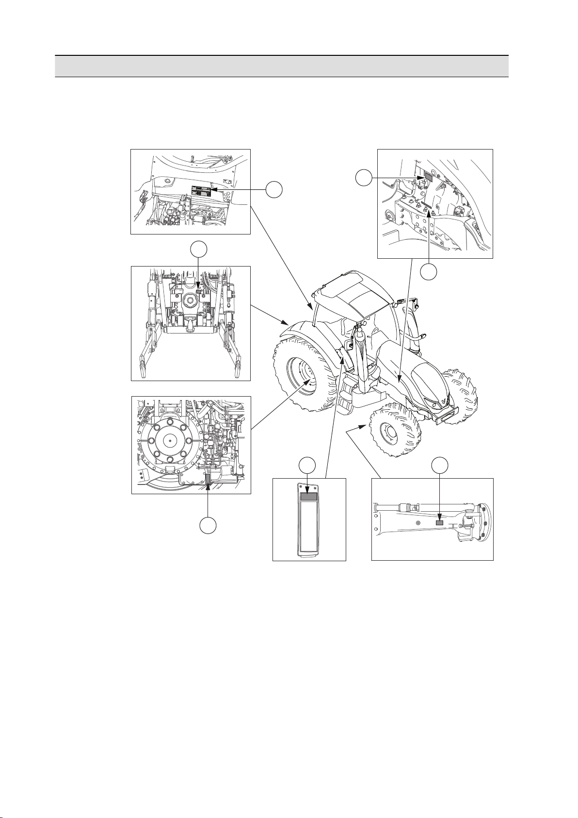
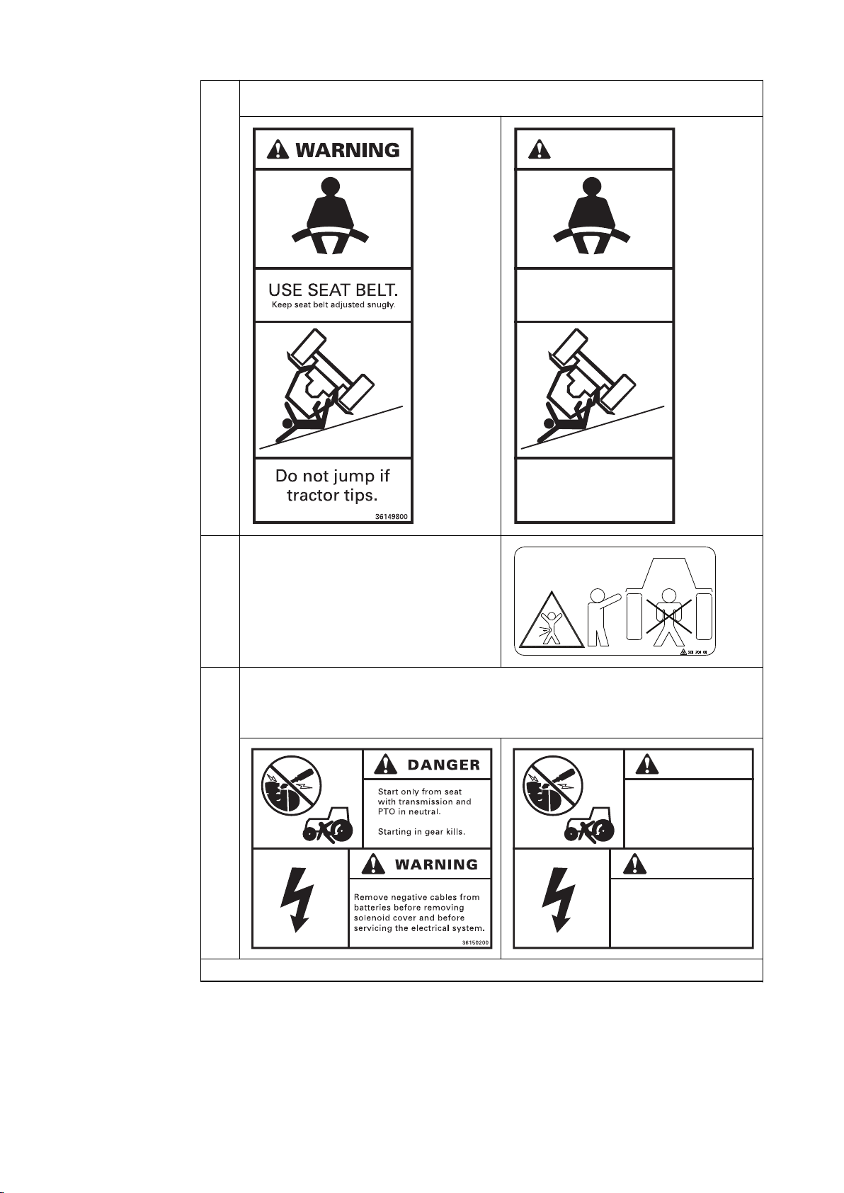
1.2.2 Safety signs
The safety signs on the tractor draw attention to possible dangers related to
certain parts or equipment of the tractor. The safety signs must be clean and
clearly visible. Worn or detached safety signs must be replaced.
- 12 -
Page 14
132314
15910
201816
16
18
2862952128
8
1. Safety precautions
IMPORTANT: After maintenance work, all replacements for parts with a safety
sign on them must include also the new safety sign.
GUID-64ABE16A-53F6-4098-9122-3795C58F65F6
- 13 -
Page 15
17
25
1
11
19426
22122773
24
ATENCIÓN
Los bornes de la batería y el resto
de los accesorios relacionados
contienen plomo y componentes de
plomo, estos compuestos pueden
producir cáncer y daños en el
aparato reproductor, según el
Estado de California.
Lávese las manos después de su
contacto.
39665500
1. Safety precautions
GUID-64799C1A-46B6-4665-82E2-95BD37BC93D9
1
Caution: Instructions on avoiding injuries during startup, driving and maintenance. Located inside the
cab, below the left-hand side C-pillar.
2 Warning: Country-specific warning concerning handling of the battery and its accessories. Located on
the side of the battery casing.
Table continued on next page
- 14 -
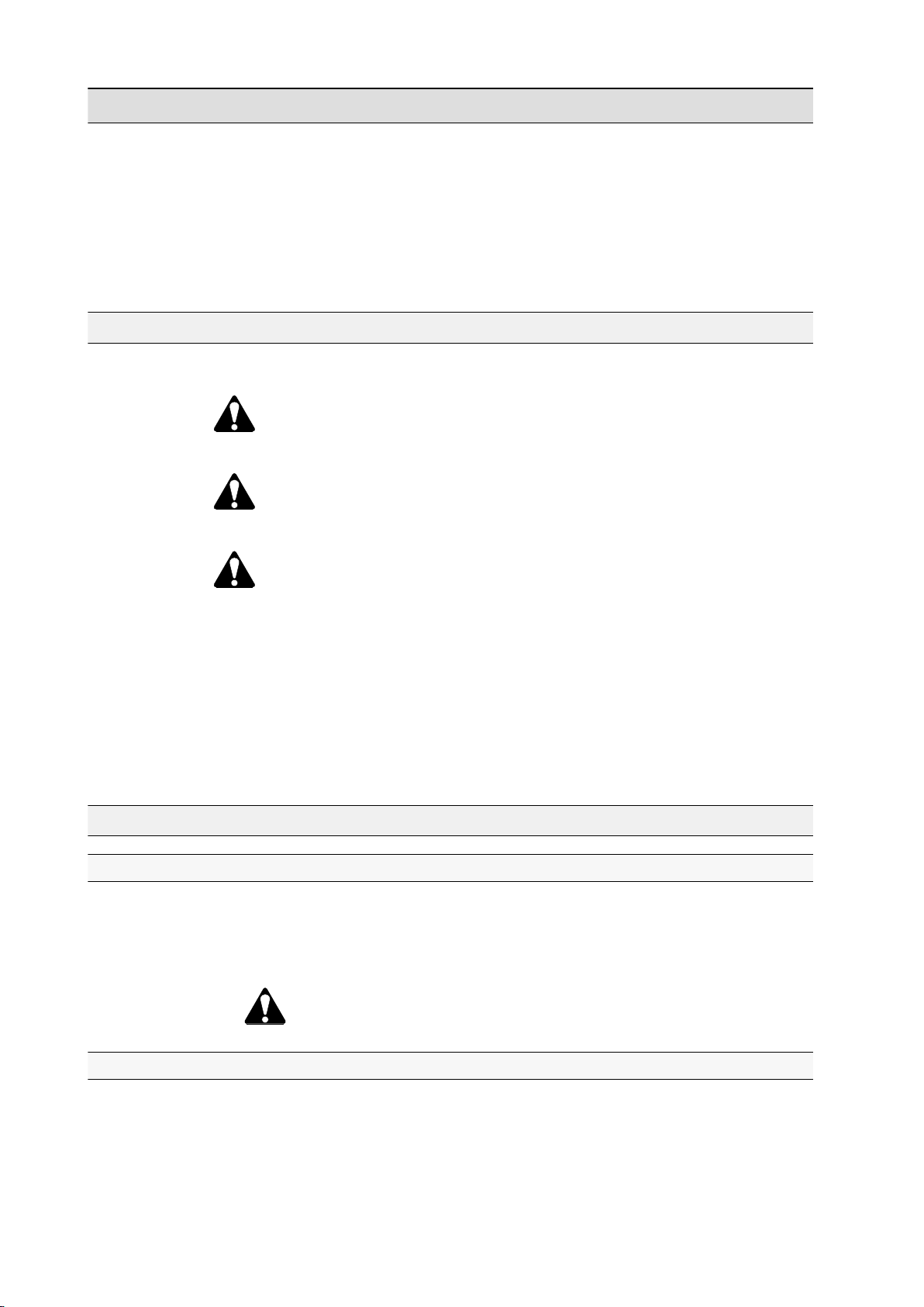
Page 16
EXPLOSIVE GASES
PELIGRO
Protección
de ojos
Explosiones
de gas
Evite chispas
y llamas
Ácido
sulfúrico
GASES EXPLOSIVOS
Proteja siempre sus ojos y cara de la batería.
Cigarros, llamas o chispas pueden causar la
explosión de la batería. No cargue, ni use
cables, ni conecte a los bornes sin seguir las
instrucciones adecuadas o recibir formación.
EL ÁCIDO causa quemaduras graves.
Contiene ácido sulfúrico. Evite el contacto
con la piel, ojos o ropa. En caso de
accidente lavar con agua abundante y
contacte con un médico inmediatamente.
Mantener fuera del alcance de los niños.
39662200
ATENCIÓN
Vapor a alta presión y
elevada temperatura.
Retire el tapón de Ilenado
con extremo cuidado.
39658300
ATENCIÓN
Precaución con las superficies
calientes.
39659400
1. Safety precautions
3 Sign indicating the location of emergency brake.
Located inside the cab, next to the right-hand
side control panels.
4
Sign indicating an emergency exit. Located inside
the cab on the rear window and on the right-hand
side window.
5
Danger: Country-specific warning that the battery and its accessories are dangerous to handle.
Located near the battery casing.
6 Warning: Country-specific warning that for some time after use the liquid in the system is hot and
under high pressure. Located under the bonnet.
7 Warning: Sign indicating the location of the hitch
locking release. Located in the cab, below the
rear window.
8
Warning: Country-specific warnings that surfaces are hot after use. Located on the marker light
support on the exhaust pipe's side of the cab.
Table continued on next page
- 15 -
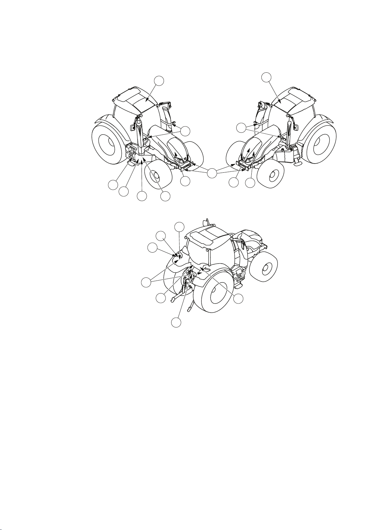
Page 17
NO MONTAR
ATENCIÓN
39649000
1. Safety precautions
9 Caution: During the connection of the front
linkage to the shut-off valve, there must be no
load on the front linkage or a rear implement
connected to the same valve. The warning sign is
located next to the shut-off valve at the back of
the tractor.
10
Country-specific warning concerning jaw locking. Located below the rear window on the outside of the
tractor.
11 Warning: Country-specific warning against standing on the stairs while the tractor is moving. Located
in the cab, behind the passenger seat.
12 Country-specific notification concerning the
power lift / front linkage. Located in the cab, near
the control panel on the right-hand side.
13
Country-specific notification concerning
connecting of implements. Located at the back of
the tractor, on the left rear wheel mudguard.
Table continued on next page
- 16 -
Page 18
“B”
“C” “D”
“A”
400mm (15.85 in)
400mm (15.85 in)
ACV0279640
400mm (15.85 in)
400mm (15.85 in)
“B”
“C” “D”
“A”
ATENCIÓN
Pueden producirse daños físicos al separar el eje cardánico de la TDF
1. La barra de tiro proporcionada tiene una distancia “A” estándar. No la cambie.
TDE RPM
DIÁMETRO DEL EJE
DISTACIA “A”
2. La distancia a los tres puntos “C” y la distancia del implemento “D” no pueden ser estándar.
Mida la distancia “B” para el rango completo de altura de
elevación para la combinación del tractor y el implemento.
Seleccione la longitud del eje cardánico de la TDF para
que no despunte a la distancia mínima “B” y tenga
holgura suficiente para la distancia máxima.
400mm (15.85 in)
400mm (15.85 in)
ACV0285740
ATENCIÓN
STOP
A C V 0178450
1. Safety precautions
14 Warning: Country-specific sign indicating the standard distances related to PTO driveline. Located at
the back of the tractor, on the left rear wheel mudguard.
15 Sign indicating location of the PTO emergency
stop. Located at the back of the tractor, below the
rear window.
Table continued on next page
- 17 -
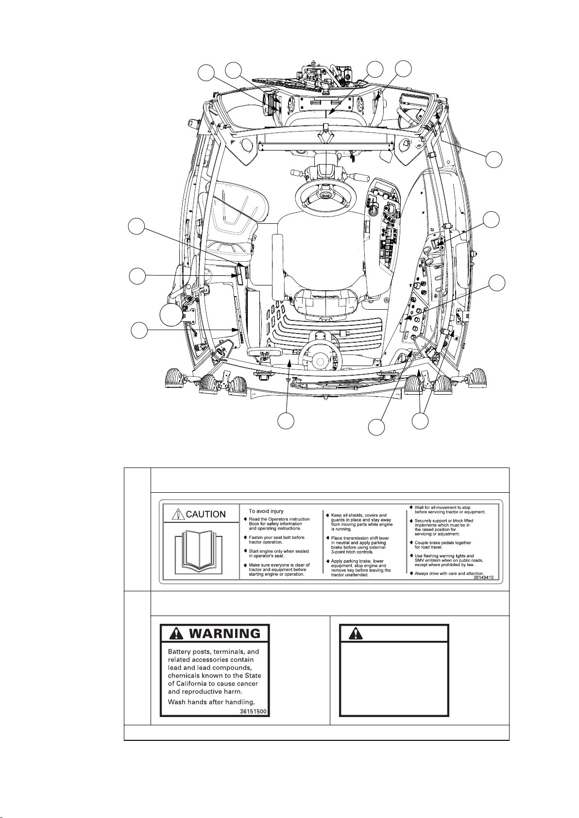
Page 19
1. Safety precautions
16 Warning: The sign warns against several
dangers:
• exposed fan which can crush and cut
• surfaces which can be hot
• exposed belt drive which can cause severe
Located under the bonnet, on both sides of the
radiator.
injury
17 Country-specific notification concerning the reverse drive system. Located in the cab, next to the
TwinTrac driving controls.
18 The sign advises how to open the roof hatch so that it can be used as an emergency exit. Located in
the cab, on the roof hatch.
Table continued on next page
- 18 -
Page 20
ATENCIÓN
USE EL CINTURÓN DE
SEGURIDAD
Mantenga su cinturón ajustado
cómodamente
No salte si el
tractor vuelca
39661600
PELIGRO
Arranque sólo desde el asiento
con el cambio de velocidades y
TDF en posición neutra.
ATENCIÓN
Retire los cables de polo negativo
de las baterías antes de retirar la
cubierta del solenoide y antes de
conectar el sistema eléctrico.
39663700
1. Safety precautions
19 Warning: Country-specific sign notifying that the seat belt must be used when driving the tractor.
Located behind the passenger seat.
20 Warning against standing directly behind the
tractor when it is used. Located at the back of the
tractor, on both rear mudguards.
21
Country-specific signs located near the battery casing.
Danger: Starting the tractor is only allowed when sitting in the seat with the transmission and PTO in
neutral.
Warning: Preparations for servicing the electrical system.
Table continued on next page
- 19 -
Page 21
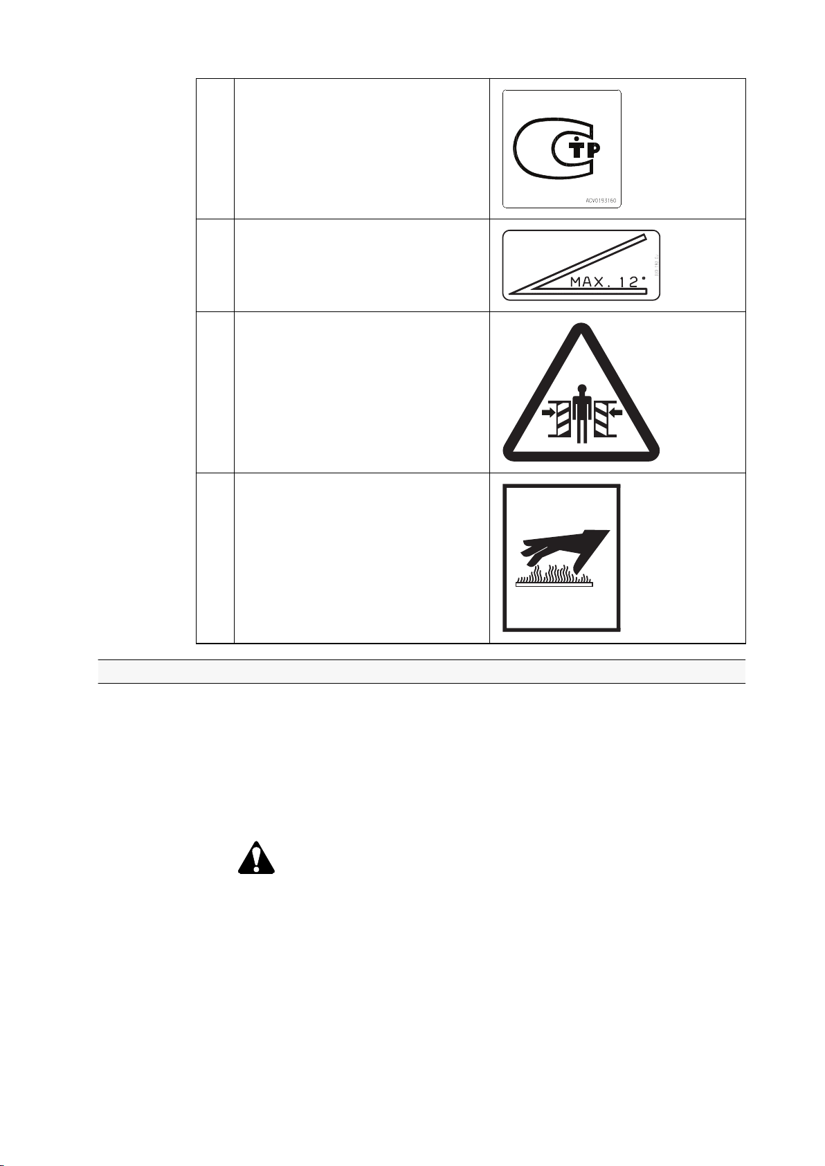
PELIGRO PELIGRO
ATENCIÓN
Realice tracción sólo con una
barra de tiro o con los brazos
inferiores del tripuntal
autorizados en posición
horizontal o inferior.
EI eje cardánico girando
puede causar daños físicos
o incluso la muerte.
Mantenga el eje cardánico
de la TDF y protecciones en
posición durante el trabajo.
Mantenga la distancia de
seguridad cuando utilice los
botones del elevador.
39665100
Brandsläckare
PULVERSLÄCKARE
Uppluckra pulvret minst
en gång per vecka.
Kontrollera att manometern
står på grönt.
1. Safety precautions
22 Country-specific warning concerning cabin tightness. Located in the cab, on the left side of the front
housing.
23 Country-specific signs located at the back of the tractor, on the left rear mudguard.
Danger: Only approved parts in their correct position can be used for pulling.
Danger: All equipment shields must be kept in place during operation.
Warning: The switch to move the three-point hitch must not be used while standing directly behind the
tractor.
24
Sign indicating the location of first aid kit. Located
on the right-hand side A-pillar.
25 Country-specific safety signs located on the front housing, next to the fire extinguisher.
Table continued on next page
- 20 -
Page 22
26 Country-specific notification concerning tractor
approval. Located in the cab, on the front
housing.
27
Country-specific notification as a reference for
surface inclination. Located in the cab, on the
windshield.
28
Warning against standing too close to the
pivoting front linkage.Located on both lifting
cylinders.
1. Safety precautions
29
Warning concerning hot surfaces. Located below
the exhaust pipe.
1.2.3 Maintaining hardware safety
To ensure maximum safety for the operator, maintain tractor hardware safety.
The owner is responsible for repairing any damage or wear which might
endanger the safety of the tractor.
• Cab
Take care that damages on the cab are repaired without delay to ensure the
cab's protective capability.
WARNING: If damage occurs to the cab, replace all affected parts
with new ones. Do not attempt any repair work (welding, drilling,
cutting or grinding) without first consulting the manufacturer.
• Tractor construction
Do not change the tractor construction, such as maximum driving speed or
maximum power.
The tractor is type-approved to comply with construction and use regulations.
Any changes to the tractor construction may reduce safety and durability and
affect the warranty terms.
- 21 -
Page 23
1. Safety precautions
• Brakes
• Always check before driving that the brakes are working.
• After attaching a trailer, check that the brakes are working.
• Lock the brake pedals together whenever individual wheel brakes are not
required and always when driving on the road.
• Extensive repairs to the braking system should be undertaken only by an
authorised Valtra workshop.
• When implements or ballast weights are front-end-mounted, the rear axle
loading is decreased.
• Make sure that steering is still effective.
• Make sure that the tractor remains stable and the rear end does not
• Use appropriate ballast weights at the rear as required.
• Do not exceed the maximum axle loads.
• Cleaning
Keep the tractor clean to decrease the risk of fire.
• Lights
• Make sure that lights and reflectors are clean and in working order.
• Make sure that the headlights are correctly adjusted.
rise up when braking.
• Steps
Keep the steps clean as dirty steps can lead to falls and injuries.
• Quick couplings
WARNING: Clean the quick couplings and ball joints before
attaching an implement. There is a risk that the implement is not
attached properly.
• Maintenance
• Follow the maintenance instructions and safety precautions applicable to
the tractor.
• Stop the engine and lower the implement before carrying out any
maintenance work on the tractor or implement.
DANGER: Support the tractor from the correct support points
on the frame and use suitable blocks or stands when carrying
out maintenance tasks that require supporting the tractor.
1.2.4 Using safety features
The tractor has several features that contribute to the safety of the operator.
• Steering wheel and safety handles
WARNING: Hold on to the steering wheel or safety handles in the
cab if the tractor tips over. Never try to jump out.
• Safety belt
Always use the safety belt when using the tractor.
- 22 -
Page 24

1. Safety precautions
• Emergency exits
Familiarise yourself with the three emergency exits of the tractor cab, that is,
the door, the rear window and the roof hatch. If necessary, the right-side
window can be broken and used as emergency exit. The windshield is
polycarbonate and cannot be easily broken.
When the tractor is equipped with the Skyview roof (optional), there is no roof
hatch which could be used as an emergency exit. The windshield is then
made of glass and can be broken and used as an emergency exit.
- 23 -
Page 25
3
451
2
1. Safety precautions
• Roof hatch
GUID-BA2C1723-EB95-4628-8964-6805ECBE1B9A
1. Direction for releasing the lock
2. Direction for detaching the spring
3. Safety sign for using the emergency exit
4. Gas springs with quick locks
5. Handle
• Pull open the sunshade.
• Turn the handle to unlock the hatch.
• Release the locking of the gas springs by pulling the spring shafts to the
direction the arrow indicates.
• Detach both gas springs from their quick locks by pulling to the direction
the arrow indicates.
• Push the hatch fully open.
WARNING: When driving on ice, keep the roof hatch open.
- 24 -
Page 26

• Emergency brake
Use the emergency brake only in emergency situations if braking with brake
pedals is not possible.
WARNING: Turning the ignition switch to (OFF) position
cannot be used as an emergency brake. The emergency brake
operates only when the power is switched on.
WARNING: Emergency brake uses the parking brake which is not
designed for continuous use. The parking brake can become
faulty.
WARNING: Using emergency brake in slippery conditions can
result in skidding and loss of control. Release the emergency
brake immediately when there is danger of wheels locking up.
Release the emergency brake only if you can do it safely.
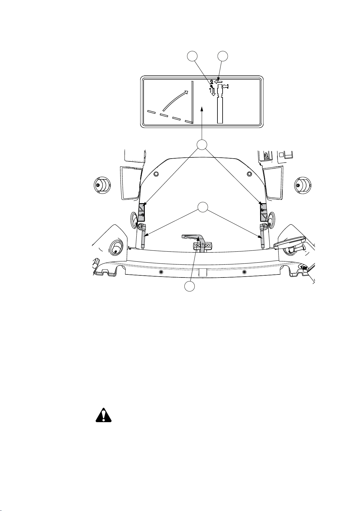
1.2.5 Safe operation
1.2.5.1 Following safe operating practices
1. Safety precautions
To operate the tractor safely, follow all safety precautions and instructions.
• Avoid operating the tractor near ditches, embankments and holes.
• Stay off slopes too steep for safe operation.
• When using chemicals, carefully follow the chemical manufacturer's
instructions for use, storage and disposal.
Also follow the chemical application equipment manufacturer's instructions.
• Protect yourself against engine noise.
Use hearing protectors to avoid injuries when you are working outside the
cab near the engine.
• Avoid carbon monoxide poisoning.
WARNING: To avoid carbon monoxide poisoning, do not start the
engine or run it indoors with the doors closed unless the exhaust is
vented to the outside.
• Restart after engine stop.
• If the engine has stalled, for example due to too heavy loading, turn the
ignition key to the Off position.
• Restart the engine. Keep an eye on the indicator lights on the instrument
panel.
- 25 -
Page 27
1
1. Safety precautions
• Do not go under the tractor.
GUID-17F24D26-0416-440F-8C1F-D28A4B0A49EE
1. Radar
WARNING: Do not go under the tractor until the ignition key has
been turned to the
with a radar (optional) it presents a hazard to your eyes.
• Front linkage
WARNING: When the front linkage is being connected to the rear
valve, make sure there is no load on the front linkage or rear
implement connected to the same valve. The load on the front
linkage or rear valve implement discharges when the shut-off
valve lever is turned. This may cause the implements to move
abruptly.
WARNING: When you drive on public roads and there is no
implement on the front linkage, the lifting links have to be folded
up.
(OFF) position. If the tractor is equipped
- 26 -
Page 28

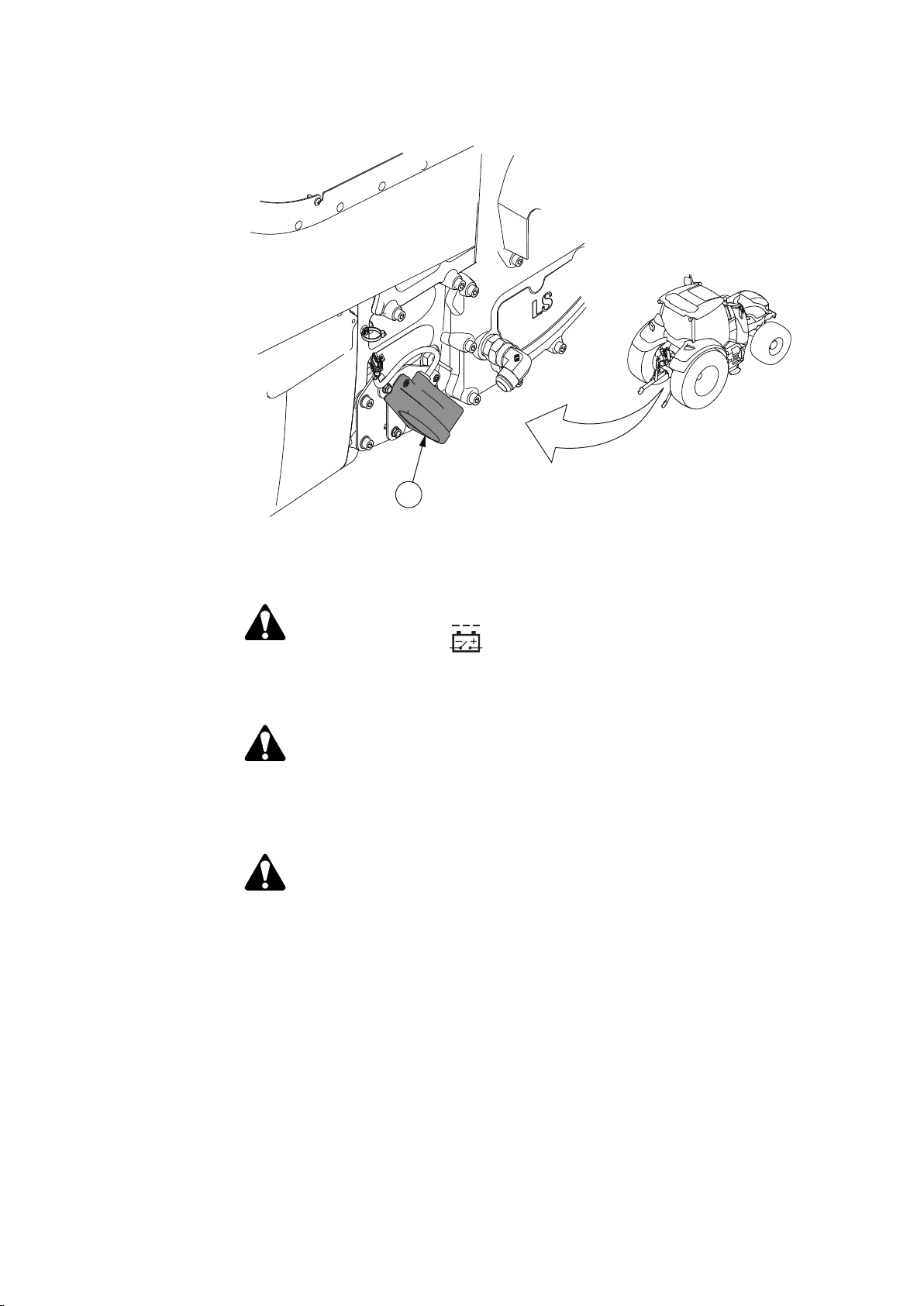
• Pivoting front linkage
WARNING: There is a danger of being squeezed between the
pivoting front linkage and the tractor's front wheels. Do not let
anyone stand within the turning range of the pivoting front linkage.
WARNING: There is a risk of overturning when working with heavy
loads or on an unstable or sloping surface or when taking sharp
turns.
WARNING: Make sure that link arms are in operating position and
that the movement range of the pivoting front linkage is clear.
WARNING: The linkage may extend farther than the tractor's
sides. This may be dangerous when driving in traffic.
WARNING: When the pivoting front linkage is being turned or if
the steering system malfunctions, the equipment may be a risk to
bystanders. Make sure there are no bystanders near the pivoting
front linkage.
WARNING: If you disengage the hydraulic system while using the
pivoting front linkage, you must reactivate the pivoting front linkage
after re-engaging the hydraulics.
1. Safety precautions
WARNING: The front wheels and the pivoting front linkage can be
turned to opposite directions, which may cause dangerous
situations.
IMPORTANT: When the front loader is in use, the pivoting front linkage must
be centered and in its top position and the lifting links must be folded to the
transport position.
• Differential lock
Use the differential lock only when running on loose or slippery ground.
• Overturning
• Always consider the way in which the tractor is to be used and the fact
that the centre of gravity of the tractor/implement assembly changes
according to the load being transported or towed.
• Adapt the tractor speed according to visibility, weather conditions and the
type of terrain.
• Do not transport loads in the top position. Transport them as low as
possible and balance the tractor with ballast weights.
• Do not accelerate, brake, turn or release clutch too suddenly when
driving on a slope.
• If possible, drive so that the heavier end of the tractor is towards the top
of the slope.
• Work situations with an increased risk of overturning include front-loader
work, lifting of heavy loads with the rear or front linkage, forest work,
especially with a boom, as well as driving on a soft, uneven or inclined
surface.
WARNING: The instructions concerning overturning in this manual
are not exhaustive.
- 27 -
Page 29

1. Safety precautions
• Hydraulic/fuel pressure
Do not attempt to locate a leak in the hydraulic system or attempt to close a
leak using any part of your body.
• Hot surfaces
• Fuel-operated heater
CAUTION: Oil/fuel under high pressure easily penetrates clothing
and skin and can cause serious injuries.
CAUTION: Be careful of hot surfaces during operation and service
work, in particular the engine and hydraulics components.
WARNING: During the heating period, clean the exhaust pipe of
the fuel-operated heater daily and its surroundings monthly. In
dusty conditions, clean more frequently. There is a risk of dry hay
or other dirt catching fire.
WARNING: When using the heater, the area directly below the
heater must be clear.
• Falling Object Protection Structure (FOPS)
DANGER: The cab structure is designed for protection against
falling objects in accordance with the OECD code 10 (energy level
1362 J). Before operating, make sure the protection is adequate
for your work conditions.
• Operator Protection Structure (OPS)
DANGER: Protection against penetrating objects is not provided
(no OPS available) if the cab of your tractor is fitted with windows
made of glass. Protection against penetrating objects is provided
in accordance with ISO 8084 (OPS is available) if the cab of your
tractor is fitted with windows made of polycarbonate, except the
Side visibility cab (no OPS in Side visibility cab). Before operating,
make sure the protection is adequate for your work conditions.
• Hazardous substances EN 15695-1:2009
DANGER: The cab is classified as category 2 according to the
draft of EN 15695-1:2009. Protection against dust is provided.
Protection against hazardous substances (agricultural chemicals,
etc.) is not provided. Personal protective equipment must be used
according to the chemical manufacturer's recommendations.
Without air conditioning and with manual air conditioning, the fan
knob position must be 3 or higher and recirculation must be
closed. With automatic air conditioning, the fan speed must be set
to maximum.
• Forest work
• When working in forest, pay special attention to safety issues. The
specific dangers related to forest work are falling or penetrating objects
and overturning, particularly when working with a boom or a winch fitted
to the rear of the tractor. For forest work, a set of forest equipment
providing additional protection is available.
- 28 -
Page 30
1.2.5.2 Getting into and out of the cab
1
When getting into and out of the cab, pay special attention to safety issues.
• Always use three-point contact with the tractor and face the tractor when
getting in and out.
• Use handrails, grab handles and steps when getting in and out.
• Do not use control levers as a handhold.
• Do not step on the pedals when getting in and out.
• Park the tractor carefully before you get out of the cab.
• Stop the tractor.
• Apply the parking brake and make sure that the parking brake symbol
shows on the instrument panel.
• If possible, stop and lower the implements.
• Never attempt to get into or out from a moving tractor.
• Never jump off a tractor.
1. Safety precautions
1.2.5.3 Driving on public roads
When driving on public roads, pay special attention to the safety issues.
• Before driving
• Check that the tractor is safe for driving on the road.
• Lock the brake pedals together with a pin.
• Adjust the rear view mirrors to give the correct viewing angle.
• Lock the check links with pins when transporting implements using three-
point linkage.
• When driving the tractor on public roads
WARNING: Do not transport anything on the auxiliary hydraulic
valves while driving on the road. The load, trailer link steering and
such have to be locked (for example mechanically).
• Use the slow moving vehicle emblem on the rear end of the tractor if
allowed by law.
GUID-CAF1D698-1F3A-4F6B-9D6F-47C26D964EC6
1. Slow moving vehicle emblem
- 29 -
Page 31

1. Safety precautions
1.2.5.4 Controlling the driving speed
Adjust the driving speed to suit the driving surface, visibility and load.
IMPORTANT: Do not alter the maximum driving speed of the tractor. The
maximum reverse driving speed is 20 km/h.
• Avoid any sudden increase or reduction (braking) in the driving speed.
• Avoid tight turns at high driving speed.
WARNING: When driving the tractor with an attached implement with
the centre of gravity far from the tractor, the tractor may sway
considerably during cornering. The tractor may tip over or the load
may be displaced.
1.2.5.5 Driving downhill
Be careful when driving downhill.
• Check the brakes often while driving downhill.
• Change to a lower gear before driving down a steep decline.
IMPORTANT: Do not brake continuously as the brakes may overheat.
IMPORTANT: Do not let the engine overrun to avoid damage to the engine.
NOTE: If the speed is too high, a speed warning is shown on the instrument
panel display and a buzzer goes off.
IMPORTANT: Engage the HillHold when starting on a slope. Otherwise the
tractor jerks downhill before traction engages even if the driving direction is
uphill.
1.2.5.6 Permitted driving inclinations
To ensure sufficient lubrication for the transmission and engine, it is essential to
follow the maximum driving angles when driving the tractor on a slope.
WARNING: Angles for safe driving should be smaller than stated to
avoid the tractor from tipping over.
Up and down slope with either front or rear end up 30°
Sideways with slope to right or left 35°
Combined slope angles; left or right / up or down
slope
Down slope to right or left 35°
Combined slope angles; right / up slope 30°/25°
Combined slope angles; right / down slope 30°/20°
Combined slope angles; left / up slope 30°/20°
Combined slope angles; left / down slope 25°/20°
25°/20°
- 30 -
Page 32

1.2.5.7 Operating with implements
Read and follow the instructions to avoid unnecessary risks when operating with
implements and attachments.
WARNING: Always follow carefully the instructions given in the
implement's user documentation. It is not allowed to use an implement
without reading and understanding all the precautions and regulations.
WARNING: Before entering between the tractor and the implement,
prevent the tractor from moving by applying the parking brake or
blocking the wheels. There is a risk of accidents if the tractor or
implement should move.
WARNING: Implements attached to the linkage or the auxiliary
hydraulic system must be lowered to the ground while parking and
during maintenance.
1. Safety precautions
WARNING: When installing an implement, air in the hydraulic hoses
and cylinders can cause erratic operation. Run the engine at a low
speed and make slow movements with the joystick to purge any air
from the hydraulic system.
WARNING: When installing an implement, keep hands and feet away
from moving components. Do not use your fingers to check the
alignment of holes or pins. Use a mandrel or a steel rod.
WARNING: When disconnecting, the implement may fall downward.
IMPORTANT: When attaching a trailer or implement, do not exceed the
maximum weight of the rear axle.
• Allow sufficient clearance for turning.
Three-point hitch and side-mounted implements make a much larger arc
when turning than towed equipment. Use only Valtra-approved attachments
and implements.
• Familiarise yourself with the working area and terrain.
Pay attention to vertical clearance and limitations that arise due to the
increased reach.
WARNING: Pull only from the approved drawbar. Attaching to other
locations and then towing may cause the tractor to overturn.
- 31 -
Page 33

1. Safety precautions
GUID-8924D3B6-EBB0-42EC-B132-A9A189E79D81
1.2.5.8 Running with power take-off driven implements or machines
Read and follow the given instructions to use power take-off (PTO) driven
implements and machines safely.
DANGER: Serious accidents may occur due to failure to use the
prescribed safety devices.
• Use the prescribed safety devices and ensure that they are in good condition.
• Follow the directions given by the implement or machine manufacturer.
1.2.5.9 Using ballast weights
Use ballast weights according to the instructions when needed.
WARNING: When driving on the road, at least 20% of the gross weight
of the tractor must be on the front axle. When lifting an implement, the
weight on the front end of the tractor is reduced and the steering ability
is impaired or sometimes lost.
IMPORTANT: When using salt liquid as ballast weight in the wheels, the
manufacturer does not take the responsibility for the damages caused by salt.
• Use sufficient ballast weights.
• Mount ballast weights only at the points intended for this purpose.
- 32 -
Page 34

1.2.5.10 Towing
Read and follow the given instructions to tow a trailer or an implement safely.
1. Safety precautions
WARNING: When the tractor is towing a trailer, the brake pedals must
be locked together. The brakes are not to be used individually for
steering.
WARNING: When using a trailer, make sure that the hitch latch is
locked.
WARNING: When using a trailer, always use the trailer brakes if
required by law. The trailer brakes are recommended to be used in 50
km/h models also in those countries where it is not required by law.
WARNING: Be sure no-one is standing between tractor and
implement.
IMPORTANT: When attaching a trailer or implement, do not exceed the
maximum weight of the rear axle or the maximum load of the tyre type and rear
axle.
• Couple a trailer to the drawbar using an approved trailer coupling.
• Always lower a loaded drawbar with the hydraulic lift.
• Check that trailer brakes are operating properly and observe any special
instructions issued by the trailer manufacturer.
• Secure the trailer load properly.
WARNING: On tractors with trailers, the load must be properly
secured. The load must not obstruct the operator's vision or cover
lights and reflectors. Loads which project more than one meter
behind the vehicle must be suitably marked. During daytime, this
should be done with a flag, and during darkness, with a red light
and a reflector arrangement.
1.2.5.11 Ensuring personal safety of other people
Avoid hazards for other people when using the tractor.
DANGER: Do not allow children in the cab or near the tractor or an
attached implement while the engine is running.
DANGER: If the tractor engine is running, do not leave anybody in the
cab without supervision, as the push buttons are easily operated.
Always apply the parking brake.
- 33 -
Page 35

1. Safety precautions
• Stop the engine and lower the implement to the ground when leaving the
tractor.
• Do not let passengers ride in the tractor unless it is provided with a special
seat.
Other personal transport, for example on front-mounted loaders, is not
permissible.
• Do not let passengers ride on the platform inside the tractor.
• Never lend the tractor to a person who is not used to driving it.
• Do not allow children or untrained or unqualified persons to operate your
tractor.
They could injure themselves or someone else.
1.2.5.12 Fire hazards
DANGER: You may be held responsible for any resulting
accidents.
WARNING: Open fire, smoking and sparks are prohibited near the fuel
system and batteries. Especially when charging batteries, explosive
gases are present.
The main switch of the battery has a main power emergency button to disconnect
the battery immediately if needed. The red-coloured push button is located below
the right fender fuse and relay board. The emergency off switching can be done
only when the ignition key is turned to the Off position.
Using the main power emergency button causes uncontrolled battery
disconnection. For example, the AdBlue urea lines are not emptied properly and
electrical control unit operating data has not been saved as designed.
1.2.5.13 Handling viton seals subjected to high temperatures
At temperatures over 300°C, the viton seals of the engine produce highly
corrosive, hydrofluoric acid.
• Do not touch viton seals subjected to abnormally high temperatures with your
bare hands.
Use neoprene rubber or heavy-duty gloves and safety glasses when
decontaminating.
• Wash seals and the contaminated area with 10% calcium hydroxide or other
alkali solution.
• Put all the removed material in sealed plastic bags and deliver them to the
point stated by the authorities concerned.
WARNING: Never burn viton seals.
- 34 -
Page 36

1.2.5.14 Aftertreatment system
The selective catalytic reduction (SCR) aftertreatment system contains copperzeolite. Copper-zeolite is not classified as hazardous.
The SCR aftertreatment system is installed in the muffler. The system is not
hazardous to health under normal use and handling.
When the SCR aftertreatment system is handled in such a way that there is a risk
of exposure to dust, safety precautions must be taken. Such work includes, for
example, opening the aftertreatment system, machining and disposing of the
aftertreatment system.
Safety instructions for work involving the SCR aftertreatment system
• Inhalation: If dust is inhaled, the affected person must be moved to fresh air.
If a considerable amount of dust has been inhaled, seek medical help.
• Contact with eyes: Rinse eyes with water for 15 minutes and with eyelids
held open. If irritation continues, seek medical help.
• Contact with skin: Wash with soap and water. Take off contaminated clothes.
• Swallowing: If you swallow a large amount, rinse mouth and then drink plenty
of water.
1. Safety precautions
Environmental hazards
Copper/zeolite is not acutely harmful to aquatic organisms. The product has not
been tested.
Precautions to protect the environment
All dust and spillage must be gathered in a container for recycling or disposal in
accordance with local regulations. Used catalysts may have different hazardous
properties than the original products.
When an SCR aftertreatment system is no longer used, it must be disposed of in
accordance with applicable EU regulations, national regulations or local
regulations.
1.2.5.15 Repair and maintenance
During repair and maintenance work, all the applicable safety precautions and
maintenance instructions have to be followed. The engine has to be stopped and
the implements lowered before any maintenance work.
Support
If the maintenance work requires supporting the tractor, the supports have to be
suitable and the tractor has to be supported from the correct support points.
When splitting the tractor, the support points and the center of gravity for each
frame part have to be considered.
Heavy components
Tools and lifting devices have to be used in the correct way. Lifting slings should
be in a vertical position and lifting and lowering should be vertical as often as
possible.
Substances
- 35 -
Page 37

1. Safety precautions
Suitable protection must be worn when handling toxic or harmful chemicals such
as fuel, oil, grease or fluids. During and after such maintenance work, all affected
parts and equipment must be carefully covered or cleaned. Excess substances
must be disposed of in the correct way.
Pressure
Pressurized circuits should not be opened immediately after the engine has
stopped. Opening pressurized circuits can be dangerous if the pressure is not
carefully released first.
Electrical system
The main power has to be turned off before disconnecting or reconnecting the
battery. The battery leads have to be connected and disconnected in the correct
order and with the correct polarity.
IMPORTANT: After maintenance work, all replacements for parts with a safety
sign on them must include also the new safety sign.
- 36 -
Page 38

2 Instruments and controls
1
234
5
2.1 One-key locking system
There is one key for locking and unlocking all the locking devices of the tractor.
• Ignition switch
• Door handle lock
• Fuel tank cap lock
• AdBlue tank cap lock
• Engine hood lock
A replacement key is available from your dealer in the event of loss or damage.
2.2 Pedals
2. Instruments and controls
GUID-A3BF0361-B682-4D15-91FA-F0A489D7275C
1. Clutch pedal
2. Locking pedal for steering wheel rake adjustment
3. Latch for brake pedals
4. Brake pedals
5. Drive pedal
- 37 -
Page 39

6
11
12
131410161723
4
5
7
8
5
20
30
40
50
0
5
0
20
25
30
1
9
15
2. Instruments and controls
2.3 Dashboard
GUID-93386ADA-DF9C-4082-AA9E-A69B37AC3C27
1. Power shuttle lever
2. Preprogramming push button
3. Lever for adjusting steering wheel position
4. Steering wheel
5. Multifunction lever
6. Proline instrument panel
7. 3-pin current socket (optional)
8. Power outlet (optional)
9. Fuel-operated heater on/off push button (optional)
10. A-pillar display
11. Control panel for A-pillar display and Proline
12. Instrument panel light dimmer
13. Hazard lights switch
14. Pressure gauge (optional)
15. Fuel-operated heater panel (optional)
16. Main power/ignition switch
17. Light switch
- 38 -
Page 40

5
20
30
40
50
0
5
0
20
25
30
1
234
5
6
5
20
30
40
50
0
5
0
20
25
30
1
234
5
3
6
7
2. Instruments and controls
2.4 Control panel for A-pillar display and Proline
GUID-983CD1D6-7614-41B0-8D19-1E07FB1000A9
1. Proline instrument panel selection
2. Arrow up
3. A-pillar display selection
4. Back
5. Arrow down
6. SET / selection
NOTE: Moving back in the selection menu automatically saves the selection.
When power is switched on, the control panel controls the Proline instrument
panel as a default.
2.5 Proline instrument panel
The operator receives information from the gauges, coolant thermometer,
tachometer, speedometer and indicator lights. All this can be seen on the Proline
instrument panel.
GUID-288866C1-6188-4BEE-8DE6-85ABC831721E
- 39 -
Page 41

cruise
RPM
cruise
KMH
min
2. Instruments and controls
1. Fuel gauge
2. Coolant temperature gauge
3. Indicator lights for turn signal
4. Tachometer
5. Speedometer
6. Indicator light for the high beam
7. Proline instrument panel display
The fuel gauge shows the amount of fuel left in the tank.
The coolant thermometer indicates the engine temperature. The zone between
blue (cold) and red (hot) is the normal operating temperature.
2.5.1 Symbols on the Proline instrument panel display
The Proline instrument panel display has fixed views and views that can be
selected by the operator.
Fixed view symbols
The fixed views are the two functions shown on the bottom row of the display:
Symbol Function
Operating hours (hhhh.h)
Clock (hh:mm)
The periodical maintenance symbol is lit on the centre row of the display when
the tractor periodical service must be carried out.
Symbol
Function
Periodical maintenance
Selectable view symbols
The selectable views are the functions shown on the top and centre row of the
display:
Symbol
km/h/mph
Function
Working time (h:mm)
Battery charge (V)
Cruise control
• RPM = engine speed
• KMH = not in use
Driving speed (km/h/mph)
Wheel slip (%, 0-100)
Rear power take-off (PTO) speed (rpm)
Front power take-off (PTO) speed (rpm)
Engine speed (rpm)
Table continued on next page
- 40 -
Page 42

l/ha
Avg
l/ha
l/h
Avg
l/h
5
20
30
40
50
0
5
0
20
25
30
2. Instruments and controls
Symbol Function
Immediate fuel consumption (ha, acre)
Average fuel consumption (ha, acre)
Immediate fuel consumption
Average fuel consumption
Fuel consumption
Lower link position (%, 0-100)
Gearbox temperature (C/F)
Travel distance (m/km/miles)
Square area (ha)
RESET Counters reset
2.5.2 Indicator lights on the left side of the display
GUID-CB29C874-ACE0-4926-913A-C3F8F4E1CE27
Indicator light
Indication
Turn signal indicator light of a vehicle combination with two trailers. The signal light
blinks when there are two trailers connected to the tractor, or one trailer with double
GUID-3B4DA5EC-8F5A-4A6B-9F05-00
3A821F23D1
lamps. If a bulb of the trailer combination has failed the light is not lit.
When the hazard lights are switched on the signal light blinks if there are four turn
signals blinking in the trailer combination.
If the turn signal indicator light is lit during the first two blinks, there is a fault in the
direction indicator relay and it must be calibrated. Contact an authorised Valtra
workshop.
Turn signal indicator light of a vehicle combination with one trailer having one pair of
lamps. The signal light blinks when there is one trailer connected to the tractor.
GUID-2A79A904-AD5A-4544-B5C3-
BB0100DB3265
When the hazard lights are switched on the signal light blinks if there are two or three
turn signals blinking in the trailer.
If the turn signal indicator light is lit during the first two blinks, there is a fault in the
direction indicator relay and it must be calibrated. Contact an authorised Valtra
workshop.
Engine emission system failure or malfunction indicator light.
The light is lit when the AdBlue/DEF tank is empty or a malfunction occurs in the SCR-
GUID-1945DB50-4F62-415E-8EFA-3B
A4A422AE5C
system. If the AdBlue/DEF is not filled or the malfunction is on, after a period of time
the light begins to flash until the error is resolved. Engine torque and speed is reduced
to avoid excessive engine exhaust emissions.
Engine air cleaner clogging indicator light.
The light is lit when the engine is running and a buzzer sounds once to indicate that the
GUID-670E595F-C714-4B9C-
B3E9-59F9EAEE02B4
engine air filter is clogged and needs to be serviced.
Table continued on next page
- 41 -
Page 43

P
F
R
S
T
O
P
5
20
30
40
50
0
5
0
20
25
30
2. Instruments and controls
Indicator light Indication
GUID-
A94E67B5-80C5-471B-94AD-90062174
2615
GUID-9ECAC14D-0D4E-4140-A7E0-
EF644A757258
GUID-578F4FB0-505C-4C35-8A38-
A986A78BBDAF
Engine oil pressure light.
The light is lit when the engine is running, a buzzer sounds continuously and the STOP
indicator light flashes to indicate that the oil pressure is too low.
Ʃ-indicator light (optional on models N134, N154E).
The light is lit continuously (yellow) when the tractor is operating in the higher power
range and using PTO.
Glow indicator light.
The light (yellow) is lit when the ignition key is in position II and the engine is cold.
Parking brake indicator light
GUID-180F20EC-F75E-4E1F-9232-
EFAB59DA1A6C
• The light (red) is lit to indicate that the parking brake has engaged
• The light blinks when the parking brake is engaging or disengaging
• The light blinks and the buzzer sounds continuously when there is a fault in the
parking brake
Low fuel level indicator light
The light is lit (yellow) and a buzzer sounds once to indicate that the fuel level is low.
GUID-4E05E947-0AFA-48E8-B011-
E6FBFD3BC3FB
The light blinks if there is water in the fuel.
Battery charging indicator light
The light is lit and a buzzer sounds once when battery charging is not ongoing.
GUID-7327F975-26FF-444E-
BF66-5428A4842D72
IMPORTANT:
A charging failure must be fixed immediately. When the voltage is reduced, the electric
valves may reduce the oil pressure for the multi-disc clutches and cause clutch
slippage which may damage the clutch discs.
2.5.3 Indicator lights on the right side of the display
GUID-4521CEDE-E696-49C4-854D-BD7748AD5DB7
- 42 -
Page 44

Indicator light Indication
STOP indicator light (red).
The light flashes to indicate serious fault.
Possible reasons:
GUID-5E3E430F-
F6C2-4C78-85F1-385620
934CD2
• Engine oil pressure too low
• Engine temperature too high (gauge)
• Gearbox oil pressure too low
• Gearbox oil temperature too high
• Hydraulic oil temperature too high
• Hydraulic oil level too low
IMPORTANT:
If the STOP light starts flashing, stop the tractor and engine immediately. You can continue
driving only in an emergency, for example to move the tractor to the roadside.
Gearbox oil pressure light.
The light is lit and the STOP indicator light flashes to indicate that the gearbox oil pressure is
GUID-F4FD89FD-
DFD9-4D66-9A65-
E079AA64E74A
too low.
Gearbox oil temperature light.
The light is lit and the STOP indicator light flashes to indicate that the gearbox oil temperature
GUIDBE46976E-2C22-4647A1D7-1640D38AEDF4
is too high.
The gearbox oil temperature can be shown on the Proline instrument panel display.
Gearbox/hydraulic oil pressure oil filter clogging indicator light.
The light is lit to indicate that the pressure filter(s) of the hydraulic or transmission system
GUID-
EB66B97E-9737-4317-94
70-085AA880C5CE
requires service. Oil filter clogging is monitored when the oil temperature is within the normal
operating range.
Four-wheel drive (4WD) indicator light.
The light is lit (yellow) to indicate that 4WD is engaged.
GUID-933C683A-
E18B-487C-
BE99-4DDE147A64A6
Front power take-off (PTO) indicator light.
The light (yellow) is continuously on and indicates that the front PTO (optional) is engaged.
GUID-A18BF127B0C4-4F56-9233-
A751CAF738F3
Auto-Guide indicator light.
The light is on (yellow) to indicate that Auto-Guide steering valve (optional) is powered on.
GUID-7509DC21-51C9-43
43-9A76-2511D9C5A4E2
Cruise control indicator light.
The light is on (yellow) to indicate that constant engine speed cruise control is engaged.
GUID-17CD4EC5-5F8C-4
B81-
ADB0-16B48368201A
Engine low oil level indicator light.
The engine oil level light (yellow) is lit if the engine oil is below low level. Engine oil level is
GUID-34B69330-
E269-4BF6-AB76-
EC7A450A9B2C
measured before the tractor is started, running engine oil level is not observed.
Differential lock indicator light.
The light is lit (yellow) to indicate that the differential lock is engaged.
GUID-26C800DE-4D35-4
423-
A349-2DE614865CE5
Rear PTO indicator light
2. Instruments and controls
GUID-C48E8C30B87F-4C58-9EE5-
E4B3C23E9E7E
• The light is lit when the PTO is on or the proportional ground speed power take-off has
been engaged
• The light blinks quickly if the PTO is rotating but no longer engaged
• The light blinks with normal speed when the PTO is not rotating and the gear selected
with the speed selection switch is engaged
• The light blinks slowly if the PTO is not rotating and the gear selected with the speed
selection switch is not engaged
• The light is not lit when the PTO is not on and the speed selection switch is in the N
position
- 43 -
Page 45

AUTO
CONTROL
STOP
124
6
789
11
12
131415163517
10
2. Instruments and controls
2.6 Controls on the right-hand side
2.6.1 Driving controls
GUID-988552FE-F03B-4288-BA84-6E33744F51D3
1. Emergency brake button
2. Push button for EcoPower (optional)
3. Switch for four-wheel drive (4WD)
4. Switch for differential lock
5. Push button for shifting automatics
6. QuickSteer control knob (optional)
7. QuickSteer activation button (optional)
8. Auto-Guide steering valve on/off button (optional)
9. Auto-Guide receiver on/off button (optional)
10. Front axle suspension switch (optional)
11. Control stop switch (optional)
12. HiShift push button
13. Powershift push button
14. Range speed push button
15. Auto-Guide remote activation button (optional)
16. Hand throttle
17. Engine RPM memory button
- 44 -
Page 46

2.6.2 Linkage
CONTROL
STOP
AUTO
3
4
5
6
7
12
13
14
8
11
10
9
1
2
2.6.2.1 Rear linkage
2. Instruments and controls
GUID-A8F7E7DB-7C86-488A-954F-24A2C36B908E
1. Lowering indicator light
2. Lifting indicator light
3. Diagnostic light
4. Lowering speed selector
5. Max lifting height selector
6. Draft control selector
7. Lifting/lowering switch
8. Trailer hitch release lever (optional)
9. Position control knob
10. Lift/stop/lower switch
11. Override button for position control knob
12. Drive balance control light
13. Drive balance control, slip control system (optional)
14. Slip control light (optional)
2.6.2.2 Front linkage
The front linkage is optional.
Connected to rear valves:
- 45 -
Page 47

1
AUTO
1
234
2. Instruments and controls
GUID-455CAFDD-A21E-4BE9-8210-17FBB7098005
1. Control lever, auxiliary hydraulics valve 4
2.6.3 Power take-off
2.6.3.1 Rear power take-off
GUID-E317BBEE-3B21-4AA7-9BDB-8B164AE824D5
1. Button for rear PTO automatic start/stop
2. Speed control knob for rear PTO
3. Switch for rear PTO when front PTO is included
4. Switch for rear PTO when front PTO is not included
- 46 -
Page 48

2.6.3.2 Front power take-off
AUTO
1
The front power take-off (PTO) is optional.
GUID-734F4190-A8CC-4AB6-B9FF-87EE76AE123C
1. Switch for front PTO
2. Instruments and controls
- 47 -
Page 49

6
1
234
5
CONTROL
STOP
2. Instruments and controls
2.6.4 Auxiliary hydraulics
The following instruments and controls are used to control the auxiliary
hydraulics.
GUID-3410366E-9235-4980-8666-56C7042C61E3
1. Control lever for auxiliary hydraulics rear valve 1
2. Control lever for auxiliary hydraulics rear valve 2
3. Control lever for auxiliary hydraulics rear valve 3 (optional)
4. Control lever for auxiliary hydraulics rear valve 4 (optional)
5. Flow control adjustment (optional)
6. Switch for rear on/off valve (optional)
- 48 -
Page 50

2.6.5 Other controls
1
234
5
6
789
10
1
2
3
GUID-5C89BBA1-A7F1-4194-BBF7-6038C3690154
1. Power outlet (optional)
2. 3-pin current socket
3. 3-pin current socket (optional)
4. ISOBUS terminal connector (optional)
5. ISOBUS bus extension connectors (behind the cover; optional)
6. Implement signal connector (optional)
7. Power switch for 2-pin current socket
8. 2-pin current socket (controlled by power switch)
9. 2-pin current socket
10. Indicator light for implement signal connection (optional)
2. Instruments and controls
2.6.6 Main power emergency button
GUID-662324B9-8FB4-4FF7-BEDB-61435F936ACF
1. Main power emergency button
2. Main power on (green light)
3. Main power off (red light)
- 49 -
Page 51

1
1
2
3
2. Instruments and controls
2.7 Controls on the rear side
2.7.1 Rear window opening latch
GUID-6B43C7C5-A73C-48E8-AE3A-7A8465D12A09
1. Rear window opening latch
2.7.2 Additional wipers
GUID-815FF11E-1BE7-4131-828E-7F42BD38D28C
1. Rear window wiper switch (optional)
2. Side window wiper switch (optional)
3. Roof window wiper switch (optional)
- 50 -
Page 52

2.7.3 Rear drive pedal
1
1
234
5
7
1
6
The rear drive pedal is optional.
GUID-E9DFC9E1-786E-472A-93FE-DDB47F0A3543
2. Instruments and controls
1. Drive pedal
2.8 Controls on the left-hand side
The following controls are positioned on the left-hand side.
GUID-CBEEB308-1F37-4109-A69A-8EABADDB4497
1. Storage compartment
2. Cool box (optional)
3. Ashtray (optional)
4. Lighter
5. Passenger seat with seat belt (optional)
6. Writing table
7. Storage pocket
- 51 -
Page 53

OK
1 2
1
2
3
4
6
789
L R
10
5
2. Instruments and controls
2.9 Controls on the right-hand side roof console
The following controls are positioned on the right-hand side roof console.
GUID-B1111944-FCC4-43FE-A805-F7A93D5177B2
1. Radio (optional)
2. Air conditioning controls
3. Tachograph (optional)
4. Mirror adjustment knob (optional)
5. Windscreen heater push button (optional)
6. Mirror heating switch (optional)
7. Interior light
8. Control switch for interior light
9. Rear window heater push button (optional)
10. Telescopic mirror adjustment knob (optional)
- 52 -
Page 54

1
234
5
6
7
9
8
2. Instruments and controls
2.10 Controls on the Skyview equipment right-hand side roof console
The following controls are positioned on the Skyview equipment right-hand side
roof console.
GUID-AA4BD9EF-08C4-43D7-A6AB-20B82EFDD7FB
1. Mirror heating switch (optional)
2. Mirror adjustment knob (optional)
3. Telescopic mirror adjustment knob (optional)
4. Air conditioning controls
5. Windscreen heater push button (optional)
6. Rear window heater push button (optional)
7. Radio (optional)
8. Control switch for interior light
9. Interior light
- 53 -
Page 55

1
234
5
6
789
2. Instruments and controls
2.11 Working light controls
GUID-F64DE483-75FF-4D51-9A29-17BDA57EDD55
1. Light panel on/off button
2. Front working lights
3. Front waist working lights (optional)
4. Rotary beacon light (optional)
5. Rear working lights
6. Automatic operation of the rear working lights
7. Trailer hitch light (optional)
8. Rear waist working lights (optional)
9. Automatic operation of the rear waist working lights (optional)
With the Skyview equipment, the button for the rear working lights also turns on
the side working lights.
- 54 -
Page 56

AUTO
AUTO
°
C
124
5
3
6
7
1
234
2. Instruments and controls
2.12 Air conditioning controls
2.12.1 Automatic air conditioning and additional heater controls
The automatic air conditioning and additional heater system is optional.
GUID-DDF9F4A0-689E-45E8-B4AA-5455ED35A00D
1. Fan speed control knob (selection OFF/Auto/Manual)
2. Defrost
3. Display
4. Air conditioning ON/OFF
5. Temperature control knob
6. Additional heater fan speed decrease (selection Manual/OFF/Auto)
7. Additional heater fan speed increase (selection ON/Manual)
2.12.2 Manual air conditioning and additional heater controls
The manual air conditioning and additional heater system is optional.
GUID-A6F90B40-8A1F-47EE-8492-6E97052B878E
1. OFF/Fan speed control knob
2. Air conditioning ON/OFF
3. Additional heater OFF/fan speed control knob
4. Temperature control knob
- 55 -
Page 57

1
2
3
1
2
2. Instruments and controls
2.12.3 Manual air conditioning
The manual air conditioning system is optional.
GUID-0913C775-1DDA-46DF-9676-D334471A4A4E
1. OFF/Fan speed control knob
2. Air conditioning ON/OFF
3. Temperature control knob
2.12.4 Heater controls
GUID-DC873987-32C9-48B4-88EC-C1CE9002D57D
1. OFF/Fan speed control knob
2. Temperature control knob
- 56 -
Page 58

2.13 Operator's seat
45162
7
3
8
2.13.1 Basic operator's seat
2. Instruments and controls
GUID-4AD10F3D-C4FE-4339-8312-D184F682AE7C
1. Seat belt anchor point
2. Forward/backward adjustment
3. Suspension adjustment
4. Storage compartment for manuals
5. Seat belt
6. Back rest tilt adjustment
7. Seat turning lock/release
8. Operator weight display
- 57 -
Page 59

off
on
234
1
6
5
789
10
11
12
2. Instruments and controls
2.13.2 Air suspended operator's seat
Air suspended operator's seat is optional.
GUID-A31C2E34-3DBB-4E21-95E9-79F162B07DB4
1. Seat depth and cushion angle adjustment
2. Headrest height adjustment and removal
3. Seat heating
4. Storage net for manuals
5. Seat turning lock/release
6. Armrest adjustment
7. Forward/backward adjustment
8. Backrest tilt adjustment
9. Longitudinal suspension adjustment
10. Height and vertical suspension adjustment
11. Suspension stiffness adjustment
12. Seat belt anchor point
- 58 -
Page 60

2.14 Controls on the rear mudguard
ON/OFF
1
2
2. Instruments and controls
GUID-47C6AE52-9D4F-437A-BA5E-92A482751A34
1. Rear power take-off on/off push button (optional)
2. Lifting/lowering push button
- 59 -
Page 61

5
1
234
2. Instruments and controls
2.15 Front end controls and connections
Front linkage and front quick couplings are optional.
GUID-C7C46DB9-88CC-4758-8518-3E918CA9FBA6
1. Engine bonnet lock
2. Trailer socket (optional)
3. Lifting/lowering push buttons for the front linkage (optional)
4. Front valve 1 push buttons (optional)
5. Front quick couplings (optional)
- 60 -
Page 62
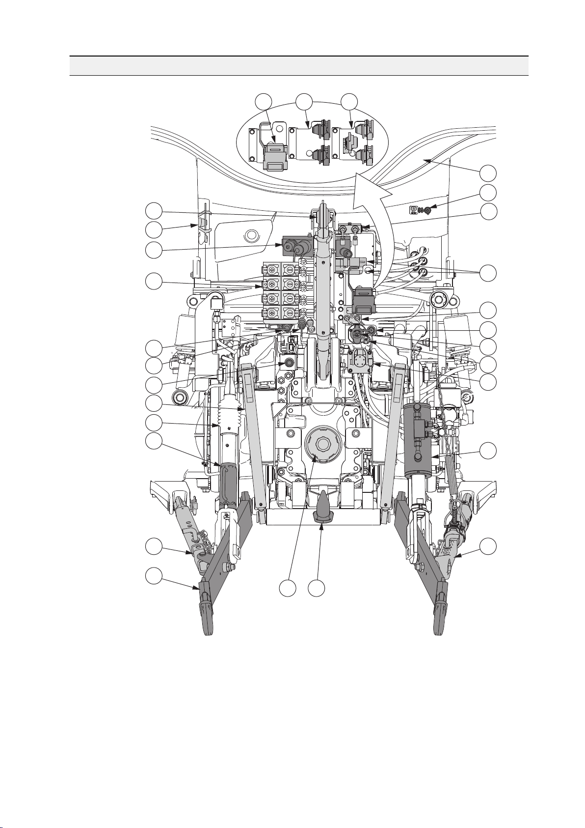
1
2
3
5
789
101213141516171819202122232425
26
27
4
28
11
6
2. Instruments and controls
2.16 Rear controls and connections outside the cab
GUID-38188FFE-BE21-4336-9A55-E9F826931813
1. Trailer coupling, Duo-Matic (optional)
2. Trailer coupling, 2-line system
3. Trailer coupling, 1-2-line system (optional)
4. Inlet for implement control cables/wires
5. Emergency stop plug for rear power take-off (PTO)
6. Front linkage shut-off valve (optional)
7. Top link
- 61 -
Page 63

2. Instruments and controls
8. Top link/lower link ball storage bracket
9. Power Beyond couplings (optional)
10. Quick couplings, auxiliary hydraulics
11. Flow control adjustment (optional)
12. On/off valve (optional)
13. Auxiliary hydraulic system return coupling
14. Case drain coupling for Power Beyond (optional)
15. Quick coupling for air pressure devices (optional)
16. Trailer socket
17. Power outlet (12 V)
18. ISOBUS connector (optional)
19. Quick coupling for hydraulic trailer brakes (optional)
20. Pick-up hitch lift links (optional together with the pick-up hitch)
21. Lift link
22. Levelling screw
23. Hydraulic levelling link (optional)
24. Side limiter
25. Automatic side limiter (optional)
26. Lower link
27. Power take-off (PTO) hatch
28. Pick-up hitch (optional)
The pick-up hitch is optional with many alternatives.
- 62 -
Page 64

3 Operation
3.1 Running the tractor in
The tractor is run in during the 50 first hours of use. Running the tractor in
correctly gives the tractor a longer service life and makes it more economical.
Before you start driving, make sure that:
• You understand all the instruments and the functions of the controls.
• You have read the safety precautions.
IMPORTANT: Check that all bolts and nuts, for example in the wheels and
exhaust system, are properly tightened.
IMPORTANT: Carry out the daily maintenance before you drive the tractor for the
first time each day.
3. Operation
When running the tractor in:
• Drive smoothly and vary the loading.
• Do not race the engine.
• Do not run the engine at maximum speed.
• Do not pull a heavy load at low engine speed.
• Avoid driving with the same gear engaged and at the same engine speed for
a long period at a time.
Check all instruments immediately after the engine has started. Keep an eye on
the instruments while driving.
3.2 Preparing for use
Before you start using the tractor, read this manual thoroughly.
• Make sure that the tractor is handled and maintained in the correct way to
ensure reliability and provide economical operation.
• Follow the maintenance program carefully and include the daily maintenance
in your normal routine.
• Use only genuine AGCO Parts spare parts for optimum performance.
3.2.1 Adjusting the driver's seat
You can adjust the driver's seat according to your height and weight. With these
adjustments you can minimize the exposure to vibration, obtain the best support
for your lower back and get the most comfortable driving position. You may need
to change the adjustments according to work conditions or the components you
are using such as the tyre type.
- 63 -
Page 65

45162
7
3
8
3. Operation
CAUTION: Do not attempt to adjust the seat while driving. There is an
increased risk of loss of control.
GUID-4AD10F3D-C4FE-4339-8312-D184F682AE7C
1. Seat belt anchor point
2. Forward/backward adjustment
3. Suspension adjustment
4. Storage compartment for manuals
5. Seat belt
6. Back rest tilt adjustment
7. Seat turning lock/release
8. Operator weight display
• Turn the seat.
• Pull the locking lever upwards to release the lock.
• Turn the seat to the desired position.
You can turn the seat 180° counterclockwise. The seat has set positions
at intervals of 10°, to be used, for example, when plowing.
• Adjust the seat forwards or backwards.
• Pull up the forward/backward adjustment lever.
• Move the seat to the desired position.
- 64 -
Page 66

3. Operation
• Adjust the suspension.
The operator weight display shows the settings for operators of different
weights.
• To increase the suspension, turn the suspension adjustment lever
clockwise.
• To decrease the suspension, turn the suspension adjustment lever
counterclockwise.
• Adjust the height of the seat.
You can lift the seat from the basic position to two higher positions.
• To lift the seat, pull it slowly upwards until you hear a click.
• To lower the seat, pull it up to the top position and then let it drop to the
desired position.
• Fasten the seat belt to the anchor point on the seat.
• Adjust the backrest inclination.
• Pull up the backrest inclination adjustment lever.
• Set the backrest to the desired position.
3.2.2 Adjusting the air-suspended driver's seat
You can adjust the air-suspended driver's seat according to your height and
weight.With these adjustments you can minimise the exposure to vibration, obtain
the best support for your lower back and get the most comfortable driving
position. You may need to change the adjustments according to work conditions
or the components you are using such as the tyre type. Power must be switched
on while adjusting the air-suspended driver's seat, but the seat has its own
compressor. The air-suspended driver's seat is extra equipment.
CAUTION: Do not attempt to adjust the seat while driving. There is an
increased risk of loss of control.
- 65 -
Page 67

off
on
1
2
6
3
4
5
8
7109
11
12
131415
3. Operation
GUID-415AF9F9-7272-4394-9E91-E403FB5E4EF0
1. Armrest adjustment (Air-suspended +)
2. Storage compartment (Air-suspended +) or net (Air-suspended) for manuals
3. Seat heating
4. Lumbar support adjustment (Air-suspended +)
5. Seat depth and cushion angle adjustment
6. Headrest height adjustment and removal
7. Seat turning lock/release
8. Armrest height adjustment
9. Backrest tilt adjustment
10. Forward/backward adjustment
11. Lateral suspension adjustment (Air-suspended + only)
12. Longitudinal suspension adjustment
13. Height and vertical suspension adjustment
14. Suspension stiffness adjustment
15. Seat belt anchor point
• Adjust the seat depth and cushion angle.
• To adjust the seat depth, pull up the right handle in the seat front.
• To adjust the seat cushion angle, pull up the left handle in the seat front.
- 66 -
Page 68

3. Operation
• Turn the seat.
• Release the lock by pulling the lock/release lever upwards.
• Turn the seat to the desired position.
The seat can be turned between 190° anti-clockwise and 90° clockwise.
The seat can be locked to set positions at 10°, 20°, 80° and 90° when
turning clockwise and 10°, 20°, 180° and 190° when turning anticlockwise.
• Adjust the seat forwards or backwards.
• Pull the forward/backward adjustment lever upwards.
• Move the seat forwards or backwards to the desired position.
• Turn the longitudinal suspension on or off.
• To turn on the longitudinal suspension, turn the lever to the rear position.
• To turn off the longitudinal suspension, turn the lever clockwise 180° to
the front position.
• Adjust the suspension according to the operator weight.
• Pull the suspension adjustment lever until the compressor starts.
The compressor runs and the suspension adjusts automatically
according to the operator's weight.
If the operator is lighter than the previous operator, the compressor runs
momentarily, the excess pressure is released, and the seat lowers.
The suspension setting remains stored in the seat memory even if the
tractor is switched off.
The seat suspension travel is 100 mm (± 50 mm) regardless of the
starting height. The suspension area is limited to 100 mm for safety
reasons.
• Adjust the height of the seat.
The seat has a stepless height adjustment range of 80 mm (±40 mm from the
seat middle position).
• Lift the seat by pulling the height adjustment lever upwards until the
desired height is reached (the seat's own compressor runs continuously
but the main power must be switched on).
When the lever is released, the compressor stops and the seat stays at
that height. If you set the seat too high so that the room for upward
movement is less than 50 mm, the seat lowers automatically to the
highest permissible position.
• Lower the seat by pressing the height adjustment lever downwards until
the desired height is reached.
If you set the seat too low so that the 50 mm downward suspension is not
possible, the seat automatically rises to the lowest limit the next time you
touch the lever.
If you sit very still on the seat during the adjustment, the seat may rise to
the previous height in the memory.
When the seat is locked at a new height, you hear a faint click.
• Adjust the stiffness of the seat suspension.
• When the lever is at the back position, the suspension is at its firmest.
• When the lever is at the front position, the suspension is at its softest.
- 67 -
Page 69

2
1
3. Operation
• Fasten the seat belt to the anchor points on the seat.
• Adjust the backrest inclination.
• Pull the backrest inclination lever up.
• Set the backrest to the desired position.
• Adjust the armrest.
• Remove the cover.
• Change the armrest position in the mounting slot.
• Adjust the lumbar support.
Turn the knob clockwise or anti-clockwise to adjust the lumbar support. The
height and depth are adjusted at the same time.
• Turn the seat heating on or off.
• Adjust the headrest height by lifting or lowering it.
• Remove the headrest by pulling it upwards.
3.2.3 Adjusting the steering wheel
You can adjust the steering wheel position with a lever and a locking pedal.
CAUTION: Do not adjust the steering wheel position while driving.
There is an increased risk of loss of control.
GUID-9C185E91-3B11-40DB-A18B-5F4F6CE81499
1. Lever for adjusting steering wheel position
2. Locking pedal for steering wheel rake adjustment
• Adjust the steering wheel position.
• Pull the lever upwards.
• Move the steering wheel up or down to the desired position.
• Push the lever down to lock the steering wheel position.
- 68 -
Page 70

• Set the steering wheel rake.
1
1
L R
2
• Press the locking pedal down.
• Adjust the steering wheel rake to the desired position.
• Release the pedal.
3.2.4 Adjusting standard mirrors
You can adjust the position of the standard mirrors manually.
GUID-84D4C889-6DC1-407F-86DA-FFD8196A71C1
3. Operation
1. Locking device of the mirror support
1. Loosen the locking device of the mirror support.
2. Adjust the mirror position.
3. Tighten the locking device.
3.2.5 Adjusting optional mirrors
You can adjust the position of the optional mirrors electrically.
GUID-7737973C-BFC2-4F4C-971A-C6793957F5FC
1. Mirror adjustment
2. Telescopic mirror adjustment
- 69 -
Page 71

1
L R
3. Operation
• Adjust the mirrors.
• To adjust the left mirror, turn the knob to the left and push the knob in the
direction of the arrows.
• To adjust the right mirror, turn the knob to the right and push the knob in
the direction of the arrows.
• Adjust the telescopic mirrors.
• To shorten/extend the left telescopic mirror, turn the knob to the left and
push the knob in the direction of the arrows.
• To shorten/extend the right telescopic mirror, turn the knob to the right
and push the knob in the direction of the arrows.
3.2.6 Heating mirrors
Mirror heating is extra equipment.
GUID-21BE979D-022A-475E-8F28-23CC9FC1A6E6
1. Mirror heating switch
• To switch the mirror heating on, press down the symbol side of the switch.
• To switch the mirror heating off, press down the side of the switch opposite to
the symbol.
- 70 -
Page 72

3.2.7 Using the windscreen wiper and washer
5
20
30
40
50
0
5
0
20
25
30
1
1
GUID-50D64ECD-35D1-4CD7-A725-22439E1BBC6D
3. Operation
1. Multifunction lever
• To use the windscreen wiper, turn the multifunction lever.
The wiper has an intermittent position and two speeds.
• To use the windscreen washer, push the lever inwards.
3.2.8 Using the side window wiper and washer
The switch for the side window wiper and washer is located on the C-pillar.
GUID-DD5ABAC1-205B-4FD2-91F7-5FC599850A31
1. Side window wiper switch
• To use the side window wiper, turn the switch.
The wiper has an intermittent position and one speed.
• To use the washer, press the switch.
- 71 -
Page 73

1
1
3. Operation
3.2.9 Using the rear window wiper and washer
The rear window wiper is extra equipment.
The switch for the rear window wiper and washer is located on the C-pillar.
GUID-C6B05D9E-0C0C-45F0-B379-DF47A9625461
1. Rear window wiper switch
• To use the rear window wiper, turn the switch.
The wiper has an intermittent position and one speed.
• To use the washer, press the switch.
3.2.10 Using the roof window wiper and washer
The switch for the roof window wiper and washer is located on the C-pillar.
GUID-6BB6F0CA-EDE0-4505-8745-2EE237DB098A
1. Roof window wiper switch
• To use the roof window wiper, turn the switch.
The wiper has an intermittent position and one speed.
• To use the washer, press the switch.
- 72 -
Page 74

3.2.11 Using the window heaters
1
L R
2
Windscreen and rear window heaters are optional equipment.
GUID-7A9E3401-C437-4B39-926D-F669934AF04B
1. Windscreen heater button
2. Rear window heater button
3. Operation
When the windscreen or rear window heater is on, the light on the button is lit.
• To switch on the windscreen heater for 10 minutes, push the windscreen
heater button.
• To switch on the windscreen heater continuously, push the windscreen
heater button more than 2 seconds.
• To switch the windscreen heater off, push the windscreen heater button
again or turn off the main power.
• To switch on the rear window heater for 10 minutes, push the rear window
heater button.
• To switch on the rear window heater continuously, push the rear window
heater button more than 2 seconds.
• To switch the rear window heater off, push the rear window heater button
again.
- 73 -
Page 75

1
P
2
1
3. Operation
3.2.12 Power shuttle lever
With the power shuttle lever you can change the driving direction and apply the
parking brake.
GUID-F9BAA5C6-A67B-4A8F-8A35-2C4E78B77A27
1. Power shuttle lever
• F (front position) = forward driving direction
• N (centre position) = neutral
• R (rear position) = reverse driving direction
• P = parking brake position
With the power shuttle, you can change the driving direction without using the
clutch pedal. However, if you use the clutch pedal, press the pedal fully down
before moving the power shuttle lever.
• With the power shuttle lever in the centre position, the parking brake can be
applied.
• When applying the parking brake, the four-wheel drive (4WD) is engaged and
all wheels brake.
• Always apply the parking brake before turning off the power.
GUID-C8DBFD22-64C1-4BCB-B3E6-5FCFD5184ECD
1. Power shuttle lever
2. Collar
- 74 -
Page 76

3.2.13 Control stop
1
The control stop is used when the tractor is running an implement in stationary
mode (for example a compressor or pump) and the operator is not in the cab.
Using the control stop reduces the risk of more serious damage to the engine or
in the transmission. The control stop is extra equipment.
NOTE: When starting the engine, the control stop must be disengaged.
Otherwise the engine does not start.
NOTE: Do not use the control stop when driving. The control stop automatically
stops the engine if the stop light is lit.
IMPORTANT: If the control stop stops the engine, the fault must be found and
repaired before the engine is started again.
3.2.14 Using the control stop
3. Operation
GUID-BA45B7C9-2B6D-4C8D-9649-5F83836A74CB
1. Control stop switch
• To activate the control stop, press down the symbol side of the control stop
switch.
Release the locking device by pushing it towards the middle of the switch.
• To deactivate the control stop, press down the side of the control stop switch
opposite to the symbol.
3.2.15 Using the ignition switch
The ignition switch has four positions: OFF, ACC, power on and start position. In
the ACC position, for example, the radio and cold box are powered.
After turning the ignition key to OFF position, there is a delay before the main
power switches off.
- 75 -
Page 77

4
5
6
1
2
3
3. Operation
GUID-3396B664-6140-46DE-9A14-D68094FD1B08
1. Ignition switch
2. Ignition key
3. OFF position
4. ACC position
5. Power on position
6. Start position
•
Turn on the power by turning the ignition key from the (OFF) position to
the (power on) position.
In cold conditions, when the engine is cold, the glow indicator light on the
instrument panel is lit.
• Start the engine by turning the ignition key from the (power on) position to
the (start) position after the glow indicator light on the instrument panel
has gone out.
• Stop the engine by turning the ignition key to the
Turn off the power by turning the ignition key to the (OFF) position.
•
First, stop the tractor, apply the parking brake, check that the parking brake
symbol (P) is lit on the instrument panel, and then turn off the power.
The tractor and several movements of the implements can be stopped if a
fault occurs by turning the ignition key to the (OFF) position. This will
make the engine stop and the transmission disengage, and the movement of
the linkage stops.
WARNING: Do not turn the ignition key to the
when the tractor is moving unless it is unavoidable.
(ACC) position.
(OFF) position
WARNING: When the power is off, the emergency brake is not in
use and the engagement of the parking brake can be delayed.
IMPORTANT: Do not keep extra keys on the same bunch with the ignition
key. It is possible that your knee touches them and turns the power off.
- 76 -
Page 78

3.2.16 Main power
1
2
3
The main power is controlled by the ignition switch.
The main power is automatically turned on when you turn the ignition key to other
than the (OFF) position. When you turn the ignition key to the (OFF)
position, the main power is turned off after a delay. During this delay, data is
saved, the system performs a controlled shutdown and the urea system lines are
emptied. The light in the light switch is lit until the main power is switched off.
The main power is not switched off automatically in the following situations:
• the parking lights are on
• the hazard warning flasher is on
• the control electronics request for additional time (maximum of one hour), for
example, the Auto-Guide system
3.2.17 Using the main power emergency button
In case of an emergency, all power can be switched off immediately without a
delay by pressing the main power emergency button when the ignition key is
removed. In normal use, the main power is switched off after a delay when you
3. Operation
turn the ignition key to the (OFF) position, and there is no need to use the
main power emergency button.
GUID-662324B9-8FB4-4FF7-BEDB-61435F936ACF
1. Main power emergency button
2. Main power on (green light)
3. Main power off (red light)
The main power emergency button has a green and a red LED light to indicate its
status.
- 77 -
Page 79

1
3. Operation
• If neither light is lit, the main power emergency button status is OFF.
• If the green light is lit, the main power emergency button status is ON.
• If the green light is blinking, the main power is shutting down with the delay.
• If the red light is blinking, the red button has been pressed while the ignition
has been in the OFF position and the main power shuts down after the delay.
This is an unlikely situation as the main power emergency button is controlled
automatically by the ignition switch.
• If the red light is lit, the red button has been pressed while driving and the
main power shuts down after the delay once the ignition has been turned to
the OFF position. This is an unlikely situation as the main power emergency
button is controlled automatically by the ignition switch.
1. Turn the ignition to the
ignition switch.
2. Open the cover of the electric centre.
3. Press the red button of the main power emergency button for three seconds.
The main power is switched off without a delay and the red light is lit in the
main power emergency button to indicate that the power is off.
NOTE: The electric system does not save data or perform controlled
shutdown and the urea lines will not be emptied.
4. Reset the main power emergency shutdown in either of the two ways.
• Press the green button of the main power emergency button.
• Disconnect a battery cable terminal.
3.2.18 Using the roof hatch
(OFF) position and remove the key from the
GUID-49C3C0CD-044D-4E66-8D04-35A192DE63FE
1. Handle
- 78 -
Page 80

1. Open the roof hatch.
• Slide the sun shade open by pulling it backward.
• Turn the handle to unlock the roof hatch.
• Push the roof hatch open.
2. Close the roof hatch.
• Pull the roof hatch closed.
• Turn the handle to lock the roof hatch.
• Slide the sun shade closed by pushing it forward.
3.3 Starting the tractor
3.3.1 Starting under normal conditions
WARNING: Never run the tractor in an enclosed building except with
the exhaust vented to the outside.
WARNING: Never start the engine unless you are seated on the
driver's seat.
3. Operation
CAUTION: Do not use starting aerosols. Due to the automatic glowing,
there is a risk of explosion.
IMPORTANT: If the engine fails to start on the first try, wait until the engine has
stopped completely before trying again.
When the power is turned on, all indicator lights in use are lit momentarily. The
following indicator lights remain on until the engine is started and the systems
operate normally:
- 79 -
Page 81

5
20
30
40
50
0
5
0
20
25
30
1
2
3
4
5
6
3. Operation
GUID-354237EC-2DE8-4CC4-9EFD-94F1A0F0A031
1. Engine oil pressure
2. Stop light (is flashing)
3. Gearbox oil pressure
4. Four-wheel drive
5. Parking brake
6. Battery charging
1. Apply the parking brake.
2. Turn the hand throttle to the low idling position.
3. Ensure that the control stop (optional equipment) is deactivated.
4. Press down the clutch pedal.
5. Turn the ignition key to the
(power on) position.
6. Wait until the glow indicator light on the instrument panel has gone out.
The glow indicator light is lit depending on temperature.
7. Turn the ignition key to the (start) position.
• When the engine starts to fire up, keep the ignition key in the (start)
position until the engine has started.
• If the engine fails to start within 10 seconds, stop starting and try again.
8. Release the ignition key when the engine starts.
When the engine starts, the following indicator lights go out:
• Engine oil pressure
• Gearbox oil pressure
• Stop light
• Battery charging
- 80 -
Page 82

9. Use the driving pedal to control the engine speed.
IMPORTANT: Never race a cold engine.
3. Operation
After starting a cold engine, the glow indicator light
afterglow reduces white smoke and keeps the cold engine running smoothly.
3.3.2 Starting under cold conditions
To ensure a successful start under cold conditions, use the engine heater or fueloperated heater and follow the instructions given.
IMPORTANT: It is recommended to use the engine heater or fuel-operated
heater when the temperature is below 0°C.
IMPORTANT: If you are driving the tractor for a short distance only, make sure
that the battery is charged enough to ensure starting.
NOTE: Use of the engine heater or fuel-operated heater reduces the wear on the
engine.
• When cold-starting the engine, turn off all unnecessary equipment that uses
electrical power.
• Keep the battery in a warm place when it is not in use.
can light up again. The
Starting the tractor under very cold conditions is easier if the battery is kept in
a warm place when it is not in use.
• Use the engine heater to ensure a successful start under cold conditions.
With the engine heater, warming up the engine for 2–3 hours before starting
is sufficient.
With the fuel-operated heater, warming up the engine for 1 hour before
starting is sufficient.
NOTE: Using the fuel-operated heater in cold conditions for more than 3
hours may empty the battery.
When the engine heater or fuel-operated heater is activated, you can hear a
hissing sound.
• If you start the engine under very cold conditions, keep the ignition key in the
(start) position until the engine has started.
IMPORTANT: Do not keep the ignition key in the
than 60 seconds at a time.
When the engine starts, the idling RPM is increased momentarily until the
RPM decreases to normal.
(start) position for more
- 81 -
Page 83

3. Operation
• If the temperature is below 0°C, first, warm up the engine and hydraulics oil
for a while at low engine speed.
Allow the engine to run for a few minutes before starting to drive or engaging
the power take-off. When first starting to use hydraulic functions, use the
predefined factory setting M2 to set the maximum flow to 50% for the first few
minutes.
• Never race a cold engine.
Run the engine with a light load until it has reached its normal operating
temperature.
3.3.3 Starting with an auxiliary battery
You can start the engine with an auxiliary battery (jump starting).
WARNING: A fully charged battery connected directly to a dead
battery can cause a current surge capable of causing the batteries to
explode.
IMPORTANT: Never use jump leads that are damaged or otherwise inadequate.
Use only well protected heavy-duty jump leads with strong clamps.
IMPORTANT: Never try to start the engine by short-circuiting leads.
1. Check that the auxiliary battery has the same voltage as the standard
battery.
2. Connect the jump lead between the (+) terminal on the auxiliary battery and
the (+) terminal on the tractor battery.
3. Connect another jump lead between the (-) terminal on the auxiliary battery
and the (-) terminal on the tractor battery.
WARNING: Make sure that the jump leads are properly connected
to the terminals. Otherwise the jump leads can cause a short
circuit, which might lead to the explosion of the battery.
4. Start the engine.
5. When the engine has started, disconnect the jump leads in the following
order:
• Remove the jump lead between the (-) terminals.
• Remove the jump lead between the (+) terminals.
- 82 -
Page 84

3.4 Using lights
5
20
30
40
50
0
5
0
20
25
30
23451
6
3.4.1 Using the light switch
3. Operation
GUID-F7FDA353-7370-4A14-90F4-292028A04B95
1. Rotary light switch
2. Off position
3. Parking lights
4. Headlights
5. Upper headlights
6. Multifunction lever
• Turn the light switch to the parking lights position to use the parking lights.
• Turn the light switch to the headlights position to use the headlights.
Working lights operate only when the parking lights or headlights are
switched on.
• If the tractor is equipped with upper headlights (optional), turn the light switch
to the far right position to use them.
NOTE: Your tractor has a safety circuitry for lights, meaning that if the fuse of
the light switch has burned and the lights are switched on, the front working
lights are forced on.
NOTE: The main power is not switched off automatically if the lights are left
on with the light switch. This feature is needed if the tractor has to be left on
the road, for example.
NOTE: The main power is not switched off automatically if the hazard
warning flasher is switched on.
- 83 -
Page 85

X130
1
3. Operation
• To turn on the high beams, pull the multifunction lever towards yourself.
GUID-9BAD42F5-6A0F-4B12-8234-9190C88A5F49
1. Connector X130
When the light switch is in the headlight position, the upper high beams
(optional) operate as an additional high beams when the connector X130
(black wire 185) is connected together. If the high beams of the upper
headlights glare, disconnect the X130 connector to turn them off.
When the light switch is in the upper headlight position, high beams operate
only on the upper headlights.
• To use the headlight flasher, pull the multifunction lever towards yourself a bit
when the dipped–beams are on.
3.4.2 Using the follow-me-home functionality
In the follow-me-home functionality, the front waist working lights (optional) are
still on even if the power is turned to the (OFF) position and you exit the cab.
• To use the follow-me-home functionality, turn the ignition key to the
(OFF) position and open the door before the main power turns off.
The follow-me-home functionality activates automatically at the same time as
the cab lights. The follow-me-home lights turn off when the cab lights or the
main power turn off.
NOTE: The main power is not turned off if the hazard warning flasher or the
parking lights are turned on. If the door is left open in such a situation, the
cab lights and the follow-me-home lights are turned off after about 10
minutes.
3.4.3 Using the working lights
The parking lights or the headlights must be switched on before you can use the
light panel. If the parking lights or the headlights are not switched on and you try
to use the light panel, the symbol on the light panel on/off button blinks few times.
- 84 -
Page 86

1
234
5
6
789
GUID-F64DE483-75FF-4D51-9A29-17BDA57EDD55
1. Light panel on/off button
2. Front working lights
3. Front waist working lights (optional)
4. Rotary beacon light (optional)
5. Rear working lights
6. Automatic operation of the rear working lights
7. Trailer hitch light (optional)
8. Rear waist working lights (optional)
9. Automatic operation of the rear waist working lights (optional)
3. Operation
With the Skyview equipment, the button for the rear working lights also turns on
the side working lights.
1. Turn the light switch to parking lights or headlights position.
The light panel and working lights turn on if the light panel and working lights
were on when the power was previously shut down.
2. Press the light panel on/off button to switch on the light panel.
You can turn on the working lights only after you have switched on the light
panel. When the panel is switched on, the symbol on the on/off button is lit
green. Previously saved working light settings are taken into use.
3. Turn the working lights on and off with the corresponding working light
buttons.
When a working light is turned on, the symbol on the working light button is lit
green. The light is lit green even if the actual working light is not installed.
4. Use the automatic rear working lights with the corresponding working light
buttons.
When the automatic operation is activated, the rear working lights are
switched on automatically when the power shuttle lever is in the reverse
position. With the Skyview equipment, the side working lights works alike.
- 85 -
Page 87

1
L R
2
3. Operation
5. Press the light panel on/off button again to switch off the light panel.
The panel can be turned off also by switching off the parking lights. When the
panel is turned off, the working light settings are saved and taken into use
when the panel is turned on again.
NOTE: The rotary beacon light (optional) can be turned on and off from the
light panel independently.
6. Turn the light switch to off position.
3.4.4 Using the cab light
The tractor is equipped with a step light(s) and cab lights.
GUID-9C953E56-E65D-4C8E-8A16-9A2D354A864F
1. Cab light
2. Cab light switch
The cab lights and step light(s) function automatically as follows:
• When the door is opened, both the cab and step lights are lit.
• When the door is closed, the lights go out in 10 seconds.
• If the door is left open, the lights go out in 10 minutes.
The cab light switch has three positions: left, centre and right.
• To turn on the cab lights, push the switch to the right.
Two white cab lights are continuously on but the red LED light is off.
• To turn off the cab lights, push the switch to the centre position.
The two white cab lights and step light(s) are turned on only when the door is
opened. The red LED light is not on.
• To turn on the red panel light, push the switch to the left.
The red LED light is continuously on, and the two white cab lights are turned
on when the door is opened.
- 86 -
Page 88

3.4.5 Using the torch
1
2
3
The torch (optional) is fitted in the holder in the cab's left B-pillar.
3. Operation
GUID-AC92A84F-5EB5-4EFF-A4AC-3C632F48FF45
1. Torch
2. Torch on/off button
3. Battery charge indicator light
The magnet at the bottom of the torch allows you to attach it as a working light on
different surfaces. When the torch is on, the battery charge indicator light is lit as
follows:
• Not lit = battery capacity is more than 50%
• Orange = battery capacity is less than 50%
• Red = battery capacity is less than 10%
• To use the torch:
• Pull the torch from the holder.
The torch is held by a magnet.
• To lit the torch bright, push the on/off button.
• To lit the torch dimmed, push the on/off button again.
• To turn off the torch, push the on/off button for a third time.
• To charge the torch:
• Fit the torch to the holder.
When the tractor power is on, the torch is charged and green indicator
light is lit.
• Connect an auxiliary charger to the micro USB connector in the torch.
You can use, for example, a car charger or a mobile phone charger.
IMPORTANT: The torch contains a lithium battery. If the battery has gone out
of order, recycle the torch appropriately.
- 87 -
Page 89

5
20
30
40
50
0
5
0
20
25
30
1
2
5
20
30
40
50
0
5
0
20
25
30
1
3. Operation
3.5 Using notification devices
3.5.1 Using turn signals
GUID-425CF0C2-AFB1-4410-8887-485A3207C6BA
1. Multifunction lever
2. Indicator lights for turn signals
• To switch on the left-hand side turn signal, move the multifunction lever
upwards.
• To switch on the right-hand side turn signal, move the multifunction lever
downwards.
The left or right indicator light blinks correspondingly.
3.5.2 Using the horn
GUID-39F97DFA-F605-48D5-853D-004FFCF16415
1. Horn button
- 88 -
Page 90

• To sound the horn, push the horn button.
1
5
20
30
40
50
0
5
0
20
25
30
1
3.5.3 Using the rotary beacon light
Rotary beacon light is an extra equipment.
GUID-6F8BE120-48CF-48FF-AAC3-AF25A59C59B9
1. Button for rotary beacon light
3. Operation
1. Press the button for rotary beacon light to switch the beacon on or off.
When on, the symbol on the button is lit green.
NOTE: The rotary beacon light (optional) can be turned on and off from the
light panel independently.
3.5.4 Using hazard lights
All four turn signals can be switched on to warn of a hazardous situation.
GUID-920AE15C-6FAE-4866-8C28-AC0AD8F28350
1. Hazard lights switch
1. To make all four turn signals blink, press down the symbol side of the switch.
2. To stop the blinking, press down the side of the switch opposite to the
symbol.
NOTE: If the hazard lights are on and the ignition switch is turned to
(OFF) position, the main power stays on until the hazard lights are switched
off.
- 89 -
Page 91

1
2
1
2
3
3. Operation
3.6 Heating and ventilation
3.6.1 Using the heater
GUID-DC873987-32C9-48B4-88EC-C1CE9002D57D
1. OFF/Fan speed control knob
2. Temperature control knob
• To regulate the speed of the fan, turn the fan speed control knob.
• To regulate the temperature, turn the temperature control knob.
3.6.2 Using the manual air conditioning
The manual air conditioning is optional equipment.
IMPORTANT: Use the air conditioning regularly to prevent seizing of the
compressor.
IMPORTANT: When using the air conditioning, keep the cab doors and windows
closed.
GUID-0913C775-1DDA-46DF-9676-D334471A4A4E
1. OFF/Fan speed control knob
2. Air conditioning ON/OFF
3. Temperature control knob
1. Press the air conditioning ON/OFF button to turn on the air conditioning.
The light on the air conditioning ON/OFF button is lit.
2. To regulate the speed of the fan, turn the fan speed control knob.
3. To regulate the temperature, turn the temperature control knob.
- 90 -
Page 92

1
234
3. Operation
3.6.3 Using the manual air conditioning and additional heater
The additional heater is optional equipment.
GUID-A6F90B40-8A1F-47EE-8492-6E97052B878E
1. OFF/Fan speed control knob
2. Air conditioning ON/OFF
3. Additional heater OFF/fan speed control knob
4. Temperature control knob
1. Press the air conditioning ON/OFF button to turn on the air conditioning.
The light on the air conditioning ON/OFF button is lit.
2. To regulate the speed of the fan, turn the fan speed control knob.
3. To regulate the temperature, turn the temperature control knob.
4. To blow warm air to the lower part of the cab, turn the additional heater fan
speed control knob.
5. To use the fuel-operated heater, turn the additional heater on.
WARNING: When the additional heater is turned off, coolant does
not circulate from the fuel-operated heater onwards. This causes
the fuel-operated heater to overheat, if turned on.
3.6.4 Automatic air conditioning
The automatic air conditioning system is optional equipment.
IMPORTANT: Use the air conditioning regularly to prevent seizing of the
compressor.
IMPORTANT: When using the air conditioning, keep the cab doors and windows
closed.
The operating temperature of the air conditioning is -40°C...+80°C. The display
decelerates in -30°C and stops working in -40°C.
When operating in cold conditions, the air conditioning stays in the starting mode
until the temperature of the engine coolant reaches +40°C. During the starting
mode the fan speed is at the minimum. The starting mode ends when the engine
coolant has reached the temperature of +40°C, or in the following cases:
- 91 -
Page 93

AUTO
AUTO
°
C
124
5
3
6
7
1
234
5
3. Operation
• defrost is connected
• LO mode is connected
• a different fan speed is selected manually
3.6.4.1 Automatic air conditioning control panel and display
Control panel
GUID-DDF9F4A0-689E-45E8-B4AA-5455ED35A00D
1. Fan speed control knob (selection OFF/Auto/Manual)
2. Defrost
3. Display
4. Air conditioning ON/OFF
5. Temperature control knob
6. Additional heater fan speed decrease (selection Manual/OFF/Auto)
7. Additional heater fan speed increase (selection ON/Manual)
Display
GUID-F20FB364-0A39-4A5B-BE19-605EA501B52F
1. Automatic mode
2. Fan speed
3. Set temperature
4. Additional heater
5. ECO mode
Indicator
Indication
Displayed when the automatic fan speed and the AC compressor are on.
Displays the fan speed.
Table continued on next page
- 92 -
Page 94

Displays the selected target temperature.
1
234
AUTO
AUTO
°
C
If adjusted below 16°C, LO is displayed. If adjusted over 29°C, HI is displayed.
Displays the additional heater fan status and speed (OFF, 1, 2, AUTO).
Displayed when the ECO mode (temperature control without the AC compressor switched
on) is on.
3.6.4.2 Using the automatic air conditioning
NOTE: When you start the tractor, the air conditioning automatically defaults to
the last selected adjustment.
NOTE: If the battery has been disconnected, the air conditioning system starts a
calibration process automatically when turning the fan speed control knob to
AUTO. During calibration, the air conditioning system cannot be used.
3. Operation
GUID-2B1A1B70-F454-4DD2-8498-15F6FA9B3AAB
1. Fan speed control knob
2. Display
3. Air conditioning ON/OFF
4. Temperature control knob
• To activate the automatic air conditioning system, turn the fan speed control
knob to the AUTO position.
When the automatic air conditioning and the AC compressor are active, the
LED next to the air conditioning ON/OFF button is lit and the indicator AUTO
is shown on the display. The system regulates the fan speed automatically.
• Select the target temperature with the temperature control knob.
The target temperature is shown on the display.
• To reach the maximum cooling effect, turn the knob to the extreme
cooling position.
Indicator LO is shown on the display.
• To reach the maximum heating effect, turn the knob to the extreme
heating position.
Indicator HI is shown on the display.
• To regulate the fan speed manually, turn the fan speed control knob
clockwise to the target speed.
The fan speed is shown on the display.
- 93 -
Page 95

1
234
AUTO
°
C
ECO
3. Operation
• To deactivate the air conditioning system, turn the fan control knob to the
OFF position.
3.6.4.3 Using ECO mode
Use the air conditioning ECO mode to regulate the cab temperature without the
AC compressor. In the ECO mode the system tries to achieve the target
temperature by adjusting the water valve and fan speed. This mode saves both
the battery power and fuel.
GUID-FF8F7C17-A079-44D8-B446-B6178FED1C34
1. Fan speed control knob
2. Display
3. Air conditioning ON/OFF
4. Temperature control knob
• Using the ECO mode when the air conditioning system is in the AUTO mode.
• Switch off the AC compressor by pressing the air conditioning ON/OFF
push button.
The fan speed is regulated by the system and indicators AUTO and ECO
are displayed.
• Select the target temperature with the temperature control knob.
If you turn the temperature to LO the AC compressor is automatically
turned on.
• Using the ECO mode when the air conditioning system is in the manual
mode
• Switch off the AC compressor by pressing the air conditioning ON/OFF
push button.
• Select the target fan speed with the fan speed control knob.
• Select the target temperature with the temperature control knob.
If you turn the temperature to LO the AC compressor is automatically
turned on.
• To deactivate the ECO mode:
• press the air conditioning ON/OFF button (the AC compressor is
activated), or
• turn the fan speed control knob to AUTO, or
• turn the fan speed control knob to OFF.
- 94 -
Page 96

3.6.4.4 Using the additional heater
1
234
AUTO
AUTO
°
C
1
°
C
Use the additional heater to blow air to the lower part of the cab.
The additional heater operates automatically when the air conditioning is in the
AUTO or ECO mode.
The additional heater has four modes: AUTO, fan speed 1, fan speed 2 and OFF.
GUID-5C4C2E1B-1CF1-4CEB-ABE3-52E8783259F0
1. Automatic air conditioning fan speed
2. Additional heater fan speed decrease
3. Display showing the additional heater's fan status and speed
4. Additional heater fan speed increase
3. Operation
• Using the additional heater when the air conditioning is in the AUTO mode
The air conditioning system is in the AUTO mode when either of the
indicators AUTO or AUTO-ECO are displayed.
• Press the additional heater fan speed decrease and increase buttons to
• toggle between additional heater AUTO and OFF modes
• decrease and increase the additional heater fan speed manually.
• Using the additional heater when the air conditioning is in the ECO mode
The air conditioning system is in the ECO mode when indicator ECO
displayed. In this mode, the AC compressor is off and the air conditioning fan
speed is regulated manually.
• Press the additional heater fan speed decrease and increase buttons to
toggle between speed 1, speed 2 and OFF.
3.6.4.5 Using defrost
Use defrost to clear frost or fog from windows.
GUID-68F48EE4-389E-4F1C-91EA-3FEAF62243BA
1. Defrost
- 95 -
Page 97

3. Operation
• To activate defrost, press the defrost button.
The LED next to the button is lit. When defrost is active, the fan speed is at
its maximum and the text HI is displayed.
• To deactivate defrost, press the defrost button again.
The defrosting button indicator LED goes off, and the former air conditioning
mode is restored.
3.6.5 Fuel-operated heater
The fuel-operated heater (optional equipment) uses the same fuel as the tractor
and can be used for heating the engine and the cabin. The heater heats primarily
the engine and then the cabin. The heater is controlled either with the heater
panel or remotely via mobile phone and push button on the dashboard.
WARNING: During the heating period, clean the exhaust pipe of the
fuel-operated heater daily and its surroundings monthly. In dusty
conditions, clean more frequently. There is a risk of dry hay or other
dirt catching fire.
WARNING: When using the heater, the area directly below the heater
must be clear.
NOTE: Using the fuel-operated heater in cold conditions for more than 3 hours
may empty the battery.
The fuel-operated heater can be used together with the tractor air conditioning
system. With the automatic air conditioning there are no limitations. With the
manual air conditioning and additional heater, note the following:
WARNING: Before the fuel-operated heater is used with the manual
air conditioning system, the additional heater must be set to positions
1-3 while the tractor power is on. When the additional heater is turned
off, coolant does not circulate from the fuel-operated heater onwards.
This causes the fuel-operated heater to overheat, if turned on.
- 96 -
Page 98

3.6.5.1 Installing SIM card to the mobile controlled heater
1
234
GUID-FF2D0660-F2A9-40A4-84A5-88DADF7817BB
1. Screw
2. GSM modem
3. Button
4. SIM card
3. Operation
1. Turn off the tractor power.
2. Open the cover of the electric centre.
The GSM modem is fitted at the bottom of the electric centre.
3. Loosen the screw.
4. Turn the GSM modem towards yourself.
5. Push the button to eject the SIM card holder.
6. Install the SIM-card to the holder.
7. Push the SIM card holder to its place.
8. Turn the GSM modem to its place and tighten the screw.
9. Fit the cover of the electric centre.
- 97 -
Page 99

231
1
234
3. Operation
3.7 Power outlets
3.7.1 Lighter and power outlets
A lighter socket and power outlets provides an output of 12 V DC; 10 A at a
maximum.
GUID-47FEE990-FDCD-4ACB-A4F0-83A0544070F7
1. Lighter
2. Power outlet on the front console (optional)
3. Power outlet on the right-hand side (optional)
3.7.2 Using the two-pin current socket and power switch
A 2-pin current socket provides an output of 12 V DC; 10 A at a maximum.
GUID-E202B646-103D-4035-9A74-E95E868A9D26
1. Power switch
2. 2-pin current socket
3. 2-pin current socket
4. Power outlet
The 2–pin current socket on the right hand side is active when the main power is
on.
- 98 -
Page 100

The 2–pin current socket on the left hand side and the power outlet at the rear
1
452
3
6
end of the tractor is controlled with the power switch.
• To connect the 2–pin current socket power, press down the symbol side of
the switch.
• To disconnect the 2–pin current socket power, press down the side of the
switch opposite to the symbol
3.7.3 Three-pin current socket
3. Operation
GUID-84932CF5-F38B-4026-A174-A49D117AB680
1. Three-pin current socket on the front console (optional)
2. Three-pin current socket on the right-hand side
3. Three-pin current socket on the right-hand side (optional)
4. 25 A
5. 5 A
6. Ground
The direct current is supplied through the current socket for different regulating
elements, implements etc. 5 A is available through the ignition switch and 25 A
direct from the battery. The current supply of the 25 A pin switches off after a
delay when the ignition switch is turned to the
3.7.4 Trailer socket
Socket at the rear end
Current from the tractor to the trailer is supplied through the trailer socket.
(OFF) position.
- 99 -
 Loading...