

Page 1
Manual
Page 2
SSE2L.
Service
Manual
Valleylab
5920
Boulder,
For
Copyright
All
permission
Inc
Longbow
Colorado
information
reserved.
rights
Drive,
call:
Valleylab
©
of
Valleylab
P.O.
Box
9015
80301
USA
1-800-255-8522
1991
Inc,
Contents
of
Inc.
/
publication
this
1-303-530-2300
not
may
TWX
/
reproduced
be
910-940-2514
any
in
form
without
the
written
Page 3
FOREWORD
The
following
equipment
service
described
instructions
in
this
are
manual.
for
use
only
by
personnel
qualified
to
repair
and
service
the
Caution:
REM™
Federal
is a trademark
PolyHesive®
Effective
Date:
Valleylab
Equipment
LIMITED
Valleylab
service
option,
after
delivery
defective.
factory
accident.
The
warranty
WARRANTY
Inc
warrants
for
the
period(s)
of
any
product,
of
This
in a way
periods
(USA)
and
IsoBloc®
November
Part
No.:
covered
each
set
or
part
the
product
warranty
so
does
as,
in
Valleylab's
for
Valleylab’s
law
restricts
of
Valleylab
are
945
in
this
product
forth
below.
thereof,
to
the
original
not
apply
this
Inc.
registered
1991
100
151
manual:
manufactured
Valleylab’s
which
purchaser,
to
judgment,
products
has
been
any
product,
to
affect
are
as
by
device
to
sale
trademarks
by
of
Valleylab
SSE2L-20
Electrosurgical
110
VAC
Nominal
it
to
be
free
from
defects
obligation
and
follows:
under
returned
to
which
examination
or
part
thereof,
its
stability
this
it
or
its
which
or
reliability,
or
on
the
Inc.
Generator
in
material
warranty
Distributor
is
limited
within
discloses,
has
been
or
which
order
of
and
to
the
to
Valleylab's
repaired
has
been
a
physician.
workmanship
the
repair
or
applicable
time
satisfaction,
or
altered
subjected
under
normal
use and
replacement,
period
outside
to
misuse,
at
its
shown
below
that
the
product
Valleylab's
neglect
sole
is
or
ELECTROSURGICAL
MOUNTING
FIXTURES
FOOTSWITCHES
PATIENT
STERILE
THIS
THE
OBLIGATIONS
OTHER
VALLEYLAB'S
COMMUNICATION,
SHALL
THERE
HEREUNDER
CONSEQUENTIAL
This
USA.
Boulder,
Valleylab
without
RETURN
DISPOSABLES
WARRANTY
WARRANTIES
PERSON
BE
LIMITED
ARE
NO
warranty
The
sole
State
Inc,
and
its
incurring
GENERATORS
(ALL
(ALL
MODELS)
ELECTRODES
IS IN
LIEU
OF
MERCHANTABILITY
OR
LIABILITIES
TO
ASSUME
PRODUCTS.
VALLEYLAB'S
TO
THE
WARRANTIES
OR
ELSEWHERE
DAMAGES.
the
rights
forum
for
of
Colorado,
dealers
and
any
obligation
MODELS)
OF
ALL
OTHER
ON
THE
FOR
IT
NOTWITHSTANDING
LIABILITY
AGGREGATE
WHICH
IN
CONNECTION
and
obligations
resolving
disputes
USA.
representatives,
to
make
AND
PART
ANY
OTHER
WITH
PURCHASE
EXTEND
hereunder
arising
reserve
the
same
WARRANTIES,
FITNESS
OF
VALLEYLAB.
LIABILITY
ANY
RESPECT
BEYOND
WITH THE
shall
under
the
or
similar
One
Year
from
One
Year
from date
One
Year
from
Shelf
life
only,
Sterility
only,
EXPRESSED
FOR A PARTICULAR
VALLEYLAB
IN
CONNECTION
OTHER
PROVISION
TO
THIS
PRICE
FOR
THE
THE
TERMS
SALE
OF
be
construed
or
relating
in
any
right
to
make
changes
on
date
of
invoice.
of
invoice.
date
of
invoice.
as
stated
on
as
stated
on
OR
IMPLIED,
PURPOSE,
NEITHER
WITH
HEREIN
AGREEMENT
GOODS
HEREOF.
THIS
under and
way
changes
equipment
SOLD
PRODUCT,
governed
to
this
in
equipment
previously
packaging.
packaging.
INCLUDING,
AND
ASSUMES
THE
SALE
OR
IN
ANY
OTHER
AND
PRODUCTS
BY
VALLEYLAB
VALLEYLAB
warranty
FOR
INDIRECT
by
the
is
the
built
and/or
built
and/or
DISCLAIMS
District
OF
NOR
OR
laws
WITHOUT
ALL
OTHER
AUTHORIZES
USE
OF
DOCUMENT
SOLD
TO
OR
of
the
Court
sold
by
sold
by
LIMITATION,
ANY
OF
HEREUNDER
CUSTOMER.
ANY
LIABILITY
State
of
Colorado,
for
the
them
at
any
them.
ANY
OR
County
of
time
+3
Page 4
Table
of
Contents
SECTION 1 —
INSTALLATION
есь
онл
пе
lara
aretaya
yara
1
POWER!
PROPER
POWER
ROUTINE
FOR
GROUNDING:. : Kamus
PLUG
MAINTENANCE
CLEANING
SECTION 2 —
DESCRIPTION
INDICATORS
SECTION 3 —
TECHNICAL
MONOPOLAR
BIPOLAR
OUTPUT
OUTPUT
ο
με
INPUT
OUTPUT
POWER CONTROL
INTERACTION
ο
POWER
UNEREGULARON
REM
CONTACT
AUDIO
VOLUME
COOLING
Ig
THE
SSE2b
ssc
sce
AND
INSTRUCTIONS
OF
CONTROLS,
AND
RECEPTACLES
......................
SPECIFICATIONS
o
OUTPUT
A
CHARACTERISTICS
CHARACTERISTICS
…..................
parc
ου
SOURCE
........................
cai
QUALITY
525
nombreuse
MONITOR
οντως
κανω
tie
cee
ie
e
sa
A
INSPECTIONS
ο.
......
..........
..............
........
............
ses
¡ciao o ne
enanas
eee
i
iran
..............
«τά
če
eee
es
-
RE
res
Kas
AA
1
1
1
1
1
3
7
7
7
7
7
8
8
8
8
8
9
9
9
9
SECTION 4 一
CIRCUIT
POWER
RF
GATING
DRIVER
POWER
OUTPUT
KEYING
ISOBLOC
LAMP
DESCRIPTIONS
SUPPUV
OSCILLATOR
AND
CIRCUIT
AMPLIFIER
SECTION
LOGIC
CIRCUIT
ENABLE
Sironi
SHAPING
CIRCUIT
CIRCUITRY
ee
Ce
...............
13
13
14
Y
Page 5
SECTION 4 —
CIRCUIT
DESCRIPTIONS
.
AUDIO
LEAKAGE
REM
SECTION 5 一
TESTING
OPERATIONAL
ACCEPTANCE
CIRCUIT
CANCELING
CONTACT
AND
PROCEDURES...
OUTPUT
POWER
MONOPOLAR
BIPOLAR
REM
TEST
CONTACT
RELEAKAGE
LINE
REGULATION
POWER
SAG
COOLINGFAN
LINE
FREQUENCY
PREVENTIVE
CIRCUITS . .
QUALITY
CALIBRATION
TESTING - GENERATOR
TEST
MONITOR
AND
CALIBRATION
Lure
LEVELS
HANDSWITCH
......
TEST
-lo
QUALITY
TESI
MONITOR
kasi
nere
TEST
TEST
TEST!
MAINTENANCE
~...
~
LEAKAGE
CURRENT
....................
CIRCUIT
PROCEDURES
messe
a
leje
.......
OUTPUT
eee
ant
..............
tiri
ii
TEST
.
17
..
0
-
„21
の
A
21
22
22
23
23
ld
23
......
15
17
18
19
23
24
SECTION 6 —
TROUBLESHOOTING
SECTION 7 —
ASSEMBLIES
AND
SECTION 8 —
PARTS
LIST
MASTER
LOGIC
MULTIVIBRATOR
LIMIT
OUTPUT
ISOBLOC
REM
FUSE
CHASSIS
FRONT
COQUERASSY:
BOARD
BOARD
RESISTOR
BOARD
BOARD
BOARD
BOARD
ASSY
PANEL
ASSEMBLY
.......
SCHEMATICS
.
ve sne e ver
BOARD
BOARD
.
....
...
dia
ciali
lajes
...........
esen
meer
eee
二 2 人
25
35
57
Page 6
List
of
Figures
1948.
Figure:
Figure 3 —
Figure
Figure
Figure
Figure
Figure
Figure
Figure
Figure
Figure
1~
2:-/REARMIEW:
4—
5-SSE2L
6-SSE2L
7-
8-
9—LOGICBOARD(A2)
10 — LOGIC
11 — MULTIVIBRATOR
12 - MULTIVIBRATOR
FRONT
TYPICAL
MONOEOEAR
TYPICAL
BIPOLAR
VIEW.
OUTPUT
OUTPUT
si
2:
μονο
WAVEFORMS
BLOCK
DIAGRAM
MASTER BOARD
MASTER
BOARD
BOARD
SCHEMATIC(A2)............
seen
POWER
POWER
rese
e
VS
VS
some,
LOAD-
ο
LOAD-
σος
renze
ee
.....................
.................
(A1)
....................
SCHEMATIC
(A1)
.........
......................
BOARD
BOARD
(A3)
.............
SCHEMATIC
(A3)
..
Figure
Figure
Figure
Figure
Figure
Figure
Figure
Figure
Figure
Figure
Figure
Figure
13 — LIMIT
14 — LIMIT
15 — OUTPUT
16-
17 — ISOBLOC
18 - ISOBLOC
19 - FUSE
20 — FUSE
21-
22 - REM
23 - COOLER
24 — FRONT
Figure
25 — CHASSIS
RESISTOR
RESISTOR
OUTPUT
BOARD
BOARD
REM
BOARD
BOARD
PANEL
BOARD
BOARD
BOARD
BOARD
BOARD
BOARD
ASSEMBLY
ASSEMBLY
(AS)
SCHEMATIC
(A6)
SCHEMATIC
(A7)
.......................
SCHEMATIC
(A8)
........................
SCHEMATIC
ASSEMBLY
(A4)
.............
SCHEMATIC
(A4)
..
....................
(AS)
.........
(A6)
..
.......
(A7)
............
(A8)
......--.----
(A7)
.................
(A9)
............
(A9)
.................
Figure
26 - SSE2L
MASTER
ül
SCHEMATIC
.........-----
Page 7
Service
Centers
Valleylab
Boulder,
800-255-8522
Valleylab
Prospect,
61-2-688-4888
Valleylab
Nieuwegein,
31-3402-32456
Valleylab
c/o
Lyon,
33-78-096262
Valleylab
Wichmannstrasse
Postfach
D-2000
GERMANY
0049-4089-6884
Inc
Colorado,
Australia
AUSTRALIA
Benelux
HOLLAND
France
CLIMO
FRANCE
Germany
520452
Hamburg
USA
4
52
Valleylab
London,
44-81-961-9955
Valleylab
London,
44-81-961-9955
UK
UNITED
Europe,
UNITED
KINGDOM
Middle
KINGDOM
East
and
Africa
Page 8
INTRODUCTION
This
Service
Generator.
Testing
beyond
the
generator.
of
the
Manual
Also
the
scope
generator.
covers
included
of
this
the
installation
are
sections
Instructions
manual.
The
covering
for
reader
and
basic service
the
use and
is
directed
Technical
cautions
and
to
instructions
Specifications,
warnings
the
SSE2L
Instruction
for
the
SSE2L
Circuit
concerning
Descriptions
electrosurgery
Manual
Electrosurgical
and
the
are
supplied
with
Valleylab,
sold
equipment
by
its
them
previously
CAUTIONS
WARNING:
WARNING:
WARNING:
the
wall
outlet.
WARNING:
WARNING:
generator
generator.
is
dealers
at
Risk
Electric
Electric
Electric
Electric
disassembled
any
AND
of
and
time
without
built
WARNINGS
fire.
Shock
Shock
Shock
Shock
representatives
incurring
and/or
Replace
Hazard:
Hazard:
Hazard:
Hazard:
and
energized.
sold
fuse
reserve
any
by
them.
as
Always
Do
NOT
Disconnect
Do
NOT
the
obligation
marked.
unplug
Never
the
connect a wet
the
touch
wear a grounding
right
to
generator
power
any
exposed
to
make
make
power
before
changes
the
same
before
cord
replacing
wiring
strap
in
equipment
or
similar
cleaning.
assembly
parts.
or
conductive
when
working
changes
to
the
surface
on an
built
and/or
on
generator
or
while
energized
to
the
CAUTION:
work
at a static
components.
transport
of
This
generator
control
Handle
electrostatic
contains
workstation.
the
circuit
sensitive
electrostatic
Wear a grounding
boards
by
their
components
sensitive
nonconductive
and
circuit
components.
strap
boards.
when
edges.
When
handling
Use
repairing
electrostatic
an
antistatic
the
sensitive
container
generator,
for
Page 9
SECTION
1
—
INSTALLATION
POWER
90 — 135
The
PROPER
To
ensure
The
will
extension
Undesirable
It
is
power
POWER
The
requirements
three-prong
personnel.
FOR
Vac,
SSE2L
is
designed
GROUNDING
patient
ground
flow
wire
from
the
cords
50/60
the
responsibility
to
the
SSE2L.
PLUG
SSE2L
is
shipped
for
to
Cords
THE
SSE2L
50/60
Hz
safety
in
the
power
cabinet
three-prong
or
Hz
leakage
of
with
safe
grounding.
two-prong
should
to
operate
the
the
of
the
user
an
over
electrosurgical
cable
is
generator
two-prong
to
currents
to
ensure
approved
lts
adapters.
always
be
a
wide
generator
connected
the
in
are
also
proper
hospital
purpose
The
connector
grasped
by
range
of
input
must
to
the
chassis
an
of
event
electrical
should
adapters.
affected
grounding
grade
three-prong
not
should
the
plug.
by
be
voltages
be
properly
and
internal
the
polarization
and
polarity
defeated
be
periodically
DO
NOT
within
specified
grounded.
assures
electrical
connector.
by
PULL
that
failure.
of
of
the
using
inspected
ON
THE
output
no
dangerous
Do
the
50/60
Hz
power
outlets
This
connector
extension
by
qualified
CORD
cords
regulation.
currents
use
not
input
supplying
meets
or
ITSELF.
power.
all
service
ROUTINE
We
recommend
Manual
SSE2L
obtained
describes
can
from
CLEANING
Clean
the
generator
caustic,
corrosive,
MAINTENANCE
that
the
the
recommended
be
returned
Valleylab.
INSTRUCTIONS
SSE2L
cover,
using
front
or
abrasive
SSE2L
to
Valleylab.
standard
panel
and
AND
INSPECTIONS
be
inspected
inspection,
Repair
hospital
cord.
cleaning
by
qualified
testing
parts
procedures.
Do
not
allow
materials.
service
and
or
information
Use a mild
fluids
to
The
generator
personnel
calibration
enter
procedures.
needed
detergent
the
generator.
cannot
twice a year.
to
repair
the
and
damp
Do
be
sterilized.
This
For
major
generator
cloth
to
not
use
Service
repairs
may
clean
alcohol,
the
be
the
SSE2L
Service
Manual
1
Page 10
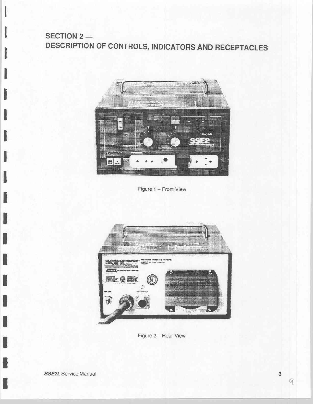
SECTION
2
—
DESCRIPTION
OF
CONTROLS,
INDICATORS
AND
RECEPTACLES
SSE2L
Service
Figure 2 —
Manual
Rear View
Page 11
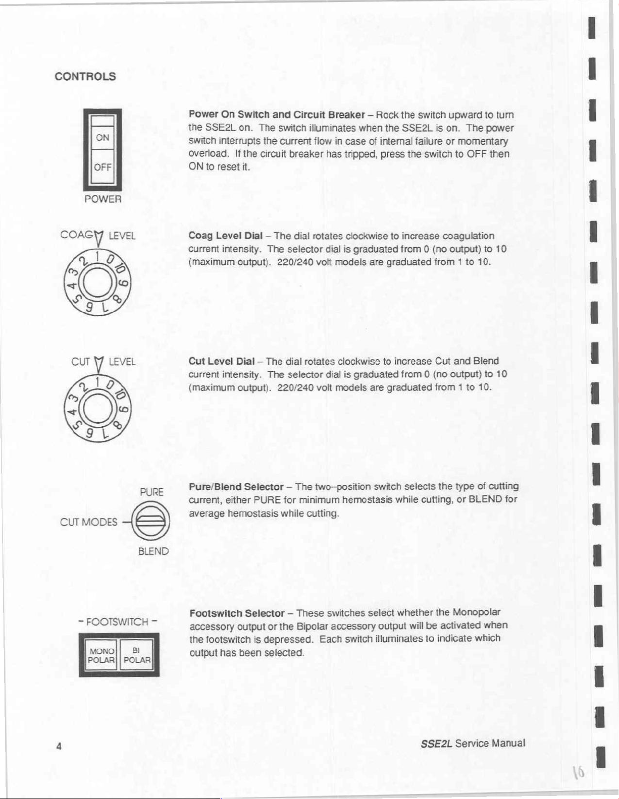
CONTROLS
COR
05,
<
410
ON
OFF
POWER
LEVEL
©
Power
the
switch
On
SSE2L
interrupts
overload.
ON
to
reset
Coag
Level
current
intensity.
(maximum
Cut
Level
current
intensity.
(maximum
Switch
on.
and
The
the
If
the
circuit
it.
Dial — The
The
output).
220/240
Dial — The
The
output).
Circuit
switch
illuminates
current
breaker
dia!
selector
dial
rotates
selector
220/240
Breaker — Rock
when
flow
in
case
has
tripped,
rotates
dial
volt
clockwise
is
graduated
models
clockwise
dial
is
graduated
volt
models
the
of
internal
press
to
are
graduated
to
increase
are
graduated
the
switch
SSE2L
is
failure
the
switch
increase
from 0 (no
coagulation
from 1 to
Cut
from 0 (no
from 1 to
upward
on.
The
or
momentary
to
OFF
output)
10.
and
Blend
output)
10.
to
turn
power
then
to
10
to
10
CUT
MODES
=
FOOTSWITCH
MONO
POLAR
POLAR
PURE
e
BLEND
Bl
—
Pure/Blend
current,
average
either
hemostasis
Footswitch
accessory
the
footswitch
output
has
Selector — The
PURE
for
minimum
while
Selector — These
Bipolar
the
or
output
is
depressed.
been
selected.
two--position
hemostasis
cutting.
switches
accessory
Each
switch illuminates
switch
while
select
output
selects
cutting,
whether
be
will
to
SSE2L
the
type
or
BLEND
the
Monopolar
activated
indicate
Service
of
cutting
when
which
Manual
for
Page 12
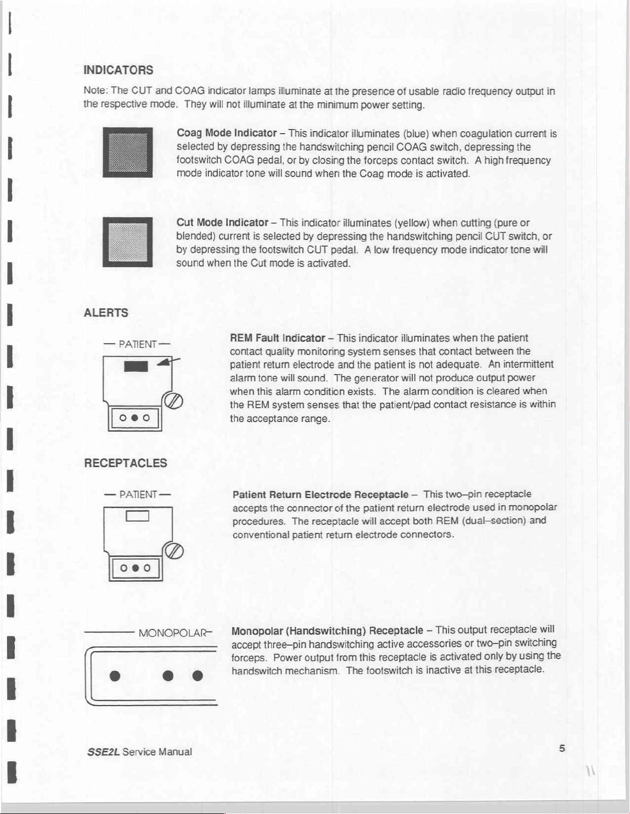
INDICATORS
Note:
The
CUT
the
respective
ALERTS
—
PATIENT
==
oeo
and
mode.
—
(の
COAG
indicator
They
will
Coag
Mode
selected
by
footswitch
mode
indicator
Cut
Mode
blended)
by
sound
current
depressing
when
lamps
illuminate
not
illuminate
at
Indicator — This
depressing
COAG
tone
the
pedal,
will
sound
or
Indicator — This
is
selected
the
footswitch
the
Cut
mode
REM
Fault
Indicator — This
contact
patient
alarm
when
the
REM
the
acceptance
quality
return
tone
this
alarm
system
ls
electrode
will
at
the
presence
the
minimum
indicator
illuminates
handswitching
by
closing
when
indicator
by
CUT
is
activated.
monitoring
sound.
condition
senses
the
the
Coag
illuminates
depressing
pedal. A low
system
and
the
The
generator
indicator
sli
exists.
that
range.
of
power
setting.
pencil
COAG
forceps
mode
(yellow)
the
handswitching
frequency
senses
patient
The
the
patient/pad
usable
(blue)
radio
when
switch,
contact
switch. A high
is
activated.
when
mode
illuminates
that
is
not
will
not
alarm
when
contact
adeguate.
produce
condition
contact
frequency
coagulation
depressing
cutting
pencil
(pure
CUT
indicator
the
patient
between
An
intermittent
output
is
cleared
resistance
output
in
current
the
frequency
or
switch,
tone
or
will
the
power
when
is
within
is
RECEPTACLES
—
PATIENT
co
oeo
MONOPOLAR-
9
SSE2L
Service
—
e
Manual
o
Patient
accepts
Return
the
procedures.
conventional
Monopolar
accept
forceps.
three-pin
Power
handswitch
Electrode
connector
The
receptacle
patient
Receptacle — This
of
the
return
electrode
(Handswitching)
handswitching
this
output
mechanism.
from
The
patient
will
return
accept
connectors.
Receptacle
active
receptacle
footswitch
two-pin
electrode
both
REM
output
This
—
accessories
activated
is
inactive
is
receptacie
used
in
monopolar
(dual-section)
and
receptacle
two-pin
or
only
this
at
switching
using
by
receptacle.
will
the
5
Page 13
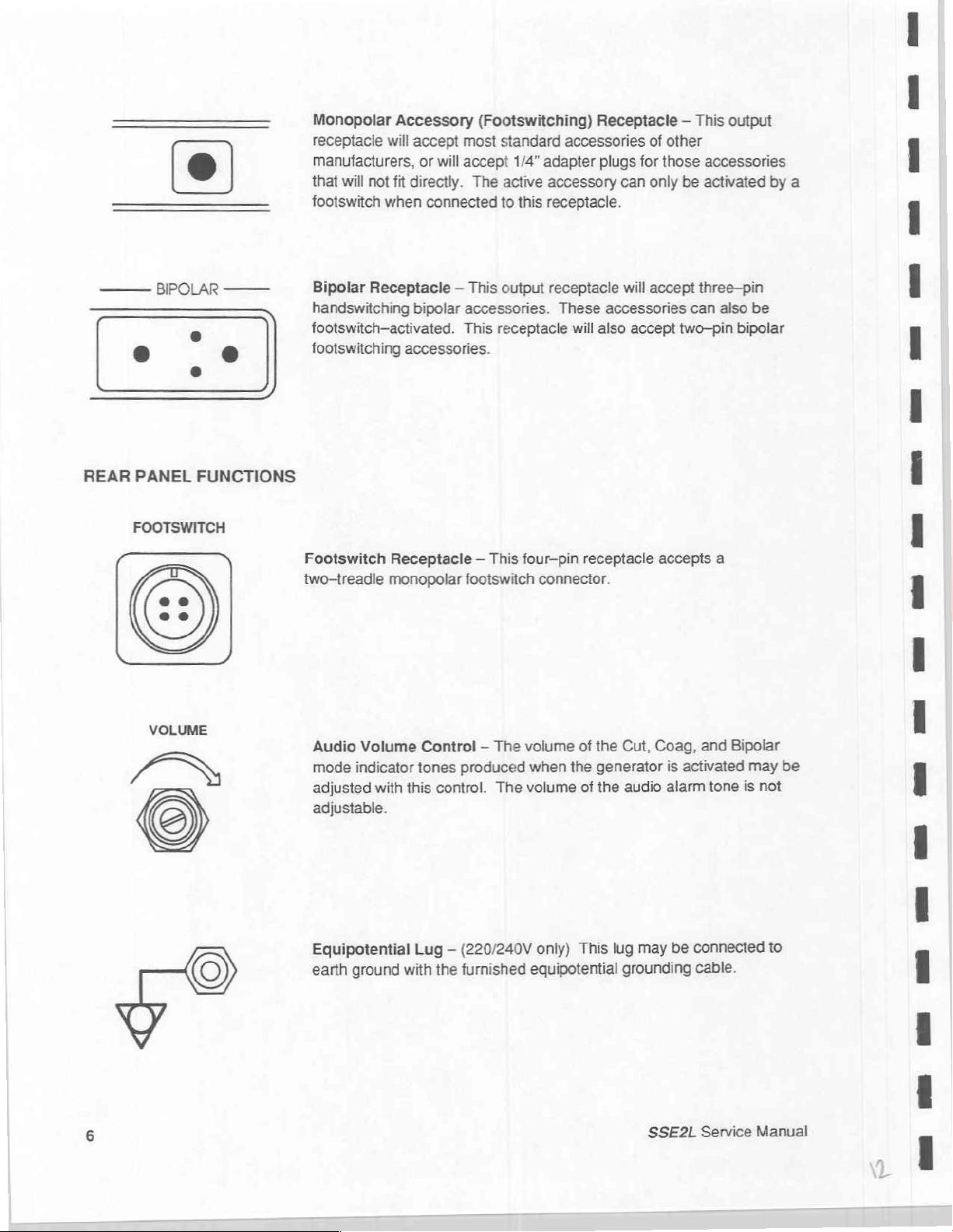
Monopolar Accessory
receptacle
manufacturers,
that
footswitch
will
not
when
will
fit
accept
directly.
or
most
will
accept
connected
(Footswitching)
The
standard
1/4”
active
to
accessories
adapter
accessory
this
receptacle.
Receptacle — This
of
other
plugs
for
those
accessories
can
only
be
activated
output
by
a
REAR
BIPOLAR
PANEL
FOOTSWITCH
FUNCTIONS
——
Bipolar
handswitching
footswitch—activated.
footswitching
Footswitch
two-treadle
Receptacle — This
bipolar
accessories.
Receptacle — This
monopolar
output
accessories.
This
receptacle
receptacle
four-pin
footswitch
connector.
These
accessories
will
also
receptacle
will
accept
accept
three-pin
can
two—pin
accepts
also
bipolar
a
be
Audio
mode
adjusted
adjustable.
Equipotential
earth
Volume
indicator
with
this
ground
with
Control — The
tones
produced
control.
Lug — (220/240V
the
furnished
volume
The
of
the
when
the
generator
volume
equipotential
only)
of
the
This
lug
Cut,
Coag,
is
activated
audio
alarm
may
be
grounding
and
Bipolar
may
tone
is
connected
cable.
be
not
to
SSE2L
Service
Manual
Page 14
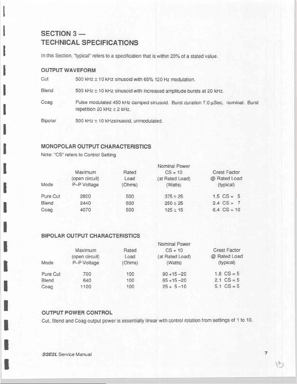
SECTION 3 —
TECHNICAL
In
this
Section,
OUTPUT
Cut
Blend
Coag
Bipolar
MONOPOLAR
Note:
Mode
"CS"
WAVEFORM
refers
SPECIFICATIONS
"typical"
500
500
Pulse
repetition
500
OUTPUT
Maximum
(open
P-P
kHz + 10
kHz + 10
modulated
kHz + 10
to
Control
circuit)
Voltage
refers
to a specification
kHz
kHz
20
kHz
kHzsinusoid,
CHARACTERISTICS
Setting
sinusoid
sinusoid
450
kHz
+ 2
kHz.
that
is
within
with
65%
120
with
increased amplitude
damped
unmodulated.
sinusoid.
Nominal
(at
20%
of a stated
Hz
modulation.
Burst
Power
CS=10
Rated
Load)
(Watts)
bursts
duration
at
value.
20
kHz.
7.0
uSec,
Crest
@
nominal.
Factor
Rated
Load
(typical)
Burst
Pure
Cut
Blend
Coag
BIPOLAR
Mode
Pure
Cut
Blend
Coag
OUTPUT
Blend
Cut,
2800
2440
4070
OUTPUT
CHARACTERISTICS
Maximum
(open
circuit)
P-P
Voltage
700
640
1100
POWER CONTROL
and
Coag
output
power
essentially
is
Nominal
(at
with
linear
375
+25
250 + 25
125215
CS = 10
Rated
(Watts)
90
+15-20
85
+15
25+
5-10
control
Power
Load)
—20
rotation
from
15
CS=
24
CS=
6.4
CS=10
Crest
Factor
@
Rated
(typical)
1.8
CS=5
2.1
CS=5
5.1
CS=5
settings
Load
1
of
5
7
to
10.
SSE2L
Service
Manual
Page 15
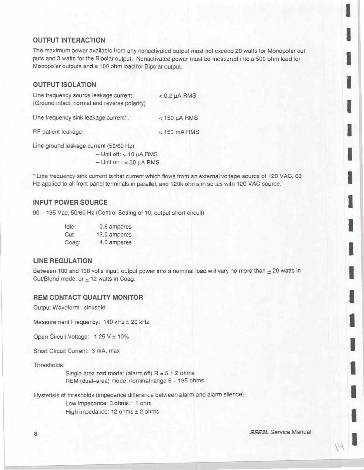
OUTPUT
The
maximum
puts
and 3 watts
Monopolar
INTERACTION
power
available
for
the
Bipolar
outputs
and a 100
from
output.
ohm
any
nonactivated
Nonactivated
load
for
Bipolar
output
power
output.
must
must
not
exceed
be
measured
20
watts
into a 500
for
Monopolar
ohm
load
out-
for
OUTPUT
Line
frequency
(Ground
Line
frequency
RF
patient
Line
ground
*
Line
frequency
Hz
applied
INPUT
90 — 135
ISOLATION
source
intact,
normal
sink
leakage:
leakage
to
all
POWER
Vac,
50/60
Idle:
Cut:
Coag:
leakage
current
sink
current
front
SOURCE
Hz
leakage
and
reverse
—
Unit
—
Unit
panel
terminals
(Control
0.6
12.0
4.0
current:
polarity)
current*:
(50/60
Hz)
off: < 10
on : <
30
is
that
current
in
Setting
amperes
amperes
amperes
<
<
<
JA
RMS
LA
RMS
which
parallel,
of
10,
and
output
0.2
150
150
flows
120k
short
uA
pA
mA
from
RMS
RMS
RMS
an
external
ohms
circuit)
in
series
voltage
with
120
source
VAC
of
120
VAC,
source.
60
LINE
REGULATION
Between
Cut/Blend
REM
Output
100
mode,
CONTACT
Waveform:
Measurement
Open
Circuit
Short
Circuit
Thresholds:
Hysterisis
of
8
and
130
volts
input,
or + 12
watts
QUALITY
MONITOR
sinusoid
Frequency:
Voltage:
Current: 3 mA,
Single
REM
Low
High
area
(dual-area)
thresholds
impedance: 3 ohms + 1
impedance:
140
1.25
V+
max
pad
mode:
mode:
(impedance
12
output
in
Coag.
kHz + 20
10%
(alarm
nominal
difference
ohms + 2
power
kHz
off) R =
range 5 —
ohm
ohms
into a nominal
5 + 2 ohms
135
between
alarm
load
ohms
and
will
vary
alarm
no
more
silence):
than + 20
SSE2L
watis
Service
Manual
in
Page 16
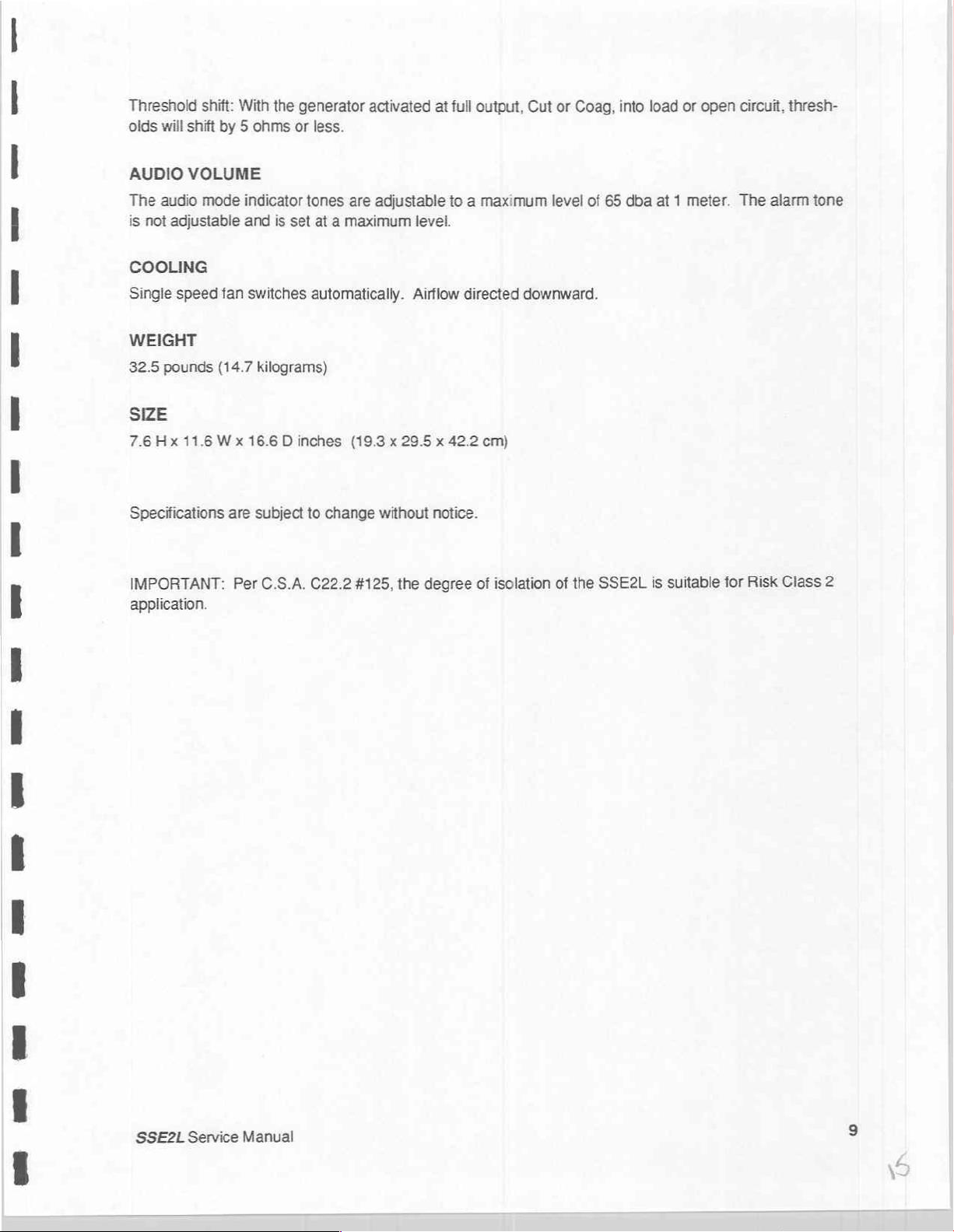
Threshold
olds
will
shift
shift:
With
by 5 ohms
the
generator
or
less.
activated
at
full
output, Cut
or
Coag,
into
load
or
open
circuit,
thresh-
AUDIO
The
is
VOLUME
audio
not
adjustable
mode
COOLING
Single
speed
fan
WEIGHT
32.5
pounds
(14.7
SIZE
7.6Hx
Specifications
IMPORTANT:
11.6
Wx
are
application.
indicator
and
is
set
switches
kilograms)
16.6 D inches
subject
Per
C.S.A.
tones
are
adjustable
at a maximum
automatically.
(19.3 x 29.5 x 42.2
to
change
C22.2
without
#125,
the
to a maximum
level.
Airflow
notice.
degree
directed
cm)
of
isolation
level
of
downward.
of
the
65
dba
SSE2L
at 1 meter.
is
suitable
The
for
alarm
Risk
tone
Class
2
SSE2L
Service
Manual
Page 17
OUTPUT
POWER
(WATTS)
400
360
320
280
240
200
160
120
80
40
9
Ὁ
200 400 600 800
PURE
CUT
|
1000 1200 1400 1600 1800
CONTROL
SETTING
CONTROL
SETTING
2000
10
5
IMPEDANCE
270
240
210
180
150
120
90
60
30
o
O
200 400 600 800
|
IMPEDANCE
(OHMS)
1000 1200
(OHMS)
1400
1600
BLEND
1800
COAG
CONTROL
SETTING
CONTROL
SETTING
2000
10
5
10
OUTPUT
POWER
(WATTS)
CONTROL
SETTING
CONTROL
So
200
400
Typical
600 800
Output
1000 1200
IMPEDANCE
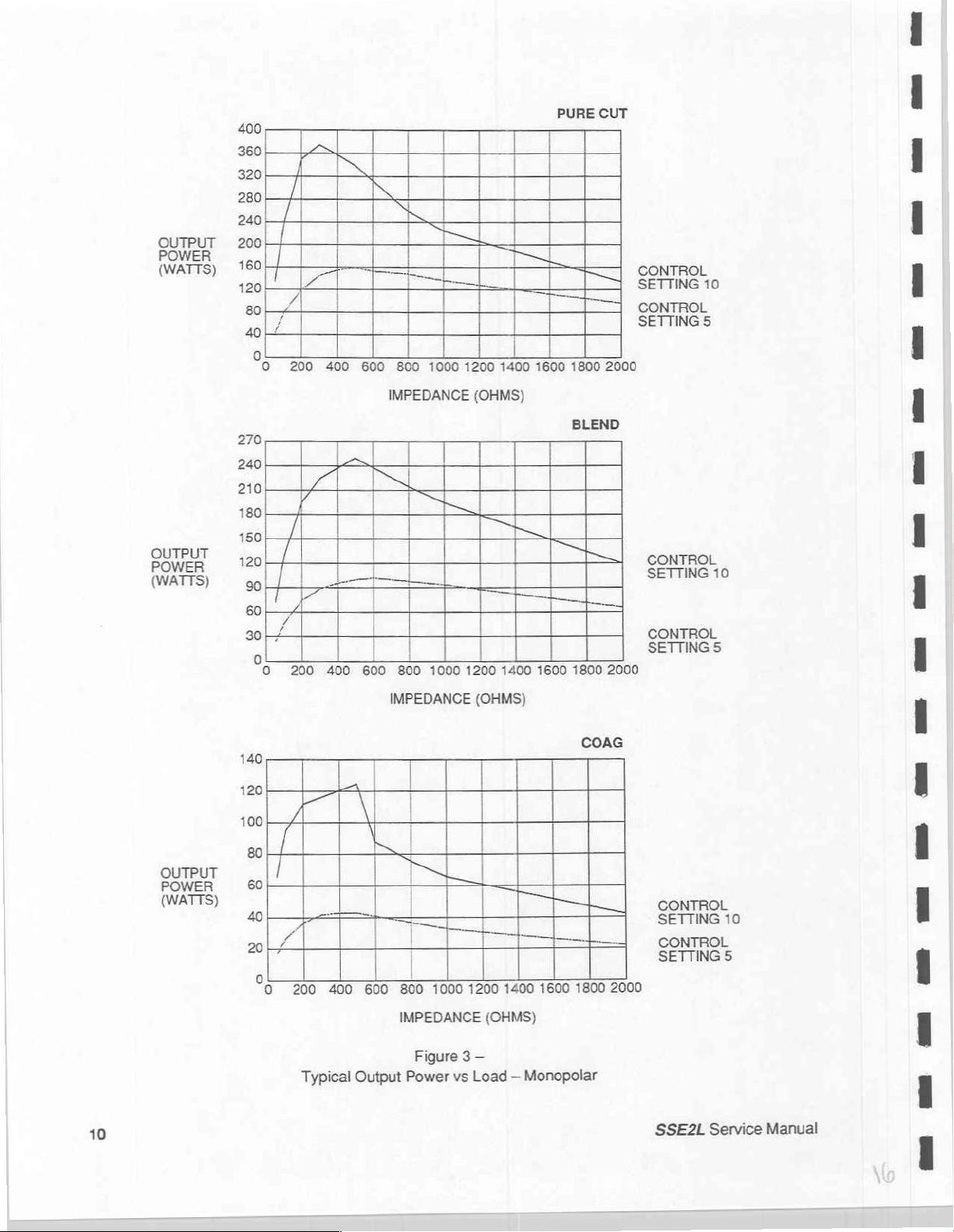
Figure 3 —
Power
vs
1400
1600
1800
(OHMS)
Load — Monopolar
SETTINGS
2000
SSE2L
10
Service
Manual
Page 18
OUTPUT
100
90
80
70
60
50
30
20
10
0
PURE
CUT
CONTROL
SETTING
CONTROL
0
200
400
600
800
1000 1200 1400
1600
1800
SETTING
2000
10
5
OUTPUT
POWER
(WATTS)
100
90
80
70
60
50
40
30
20
10
0
30
0
200
비
400
IMPEDANCE
600 800
IMPEDANCE
(OHMS)
1000 1200 1400 1600
(OHMS)
BLEND
1800
COAG
2000
CONTROL
SETTING
CONTROL
SETTINGS
10
SSE2L
OUTPUT
POWER
(WATTS)
Service
Manual
15
чо
5
6
O
A
200
i
400 600
Typical
SE
=
800
IMPEDANCE
Output
SESSI
1000
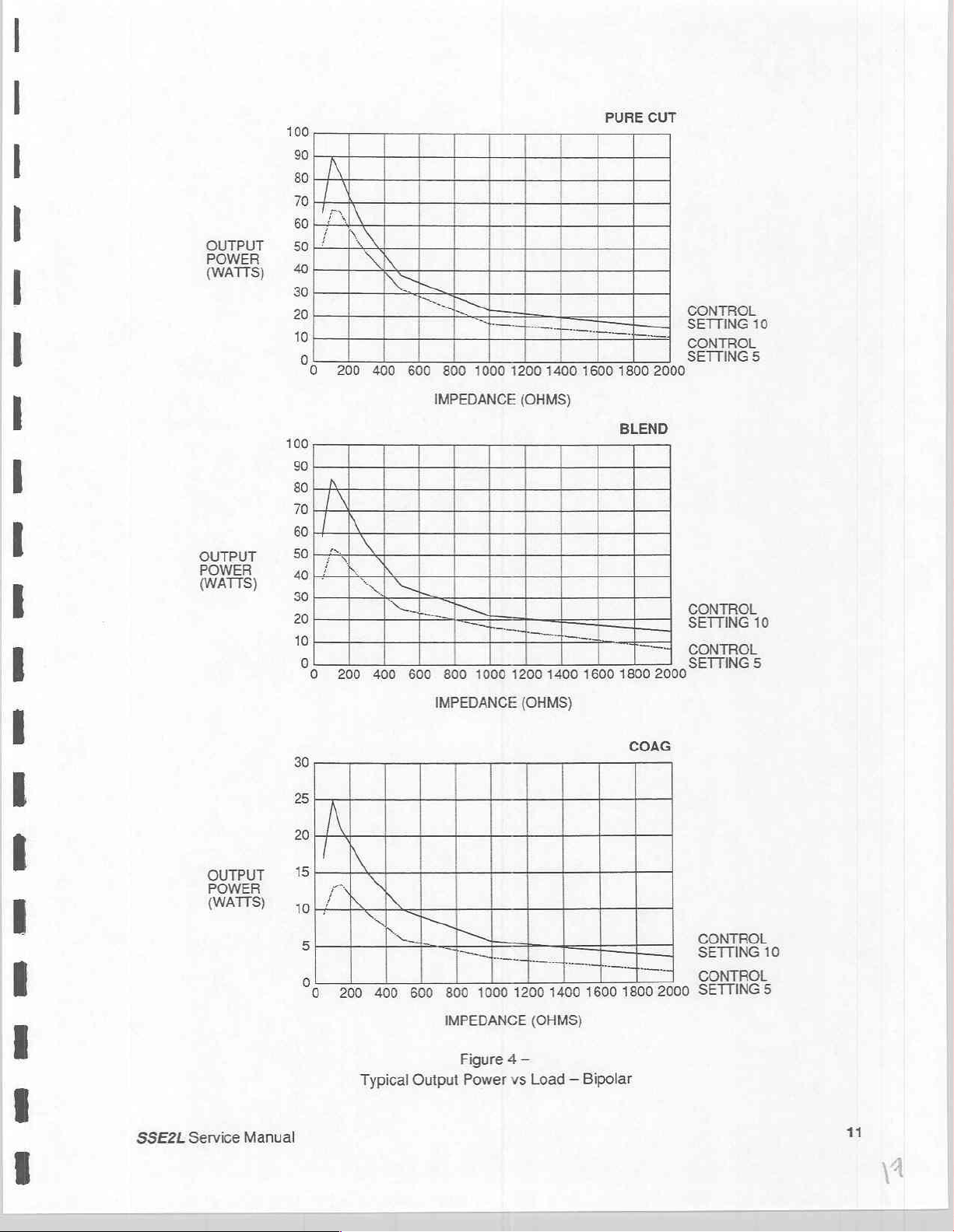
Figure
Power
1200 1400
(OHMS)
4—
vs
Load — Bipolar
1600
==]
1800
2000
CONTROL
SETTING
10
CONTROL
SETTING
5
11
Page 19
SECTION 4 —
CIRCUIT
The
SSE2L
Section,
Additionally
lamp
POWER
This
capable
this
Protected
RF
Transistors
determined
lower
T1.
Cut
450
GATING
The
resistor
waveforms.
PURE/BLEND
be
intermediate
reduced
the
amplitude
a
driver
SUPPLY
section
of
the
+20V
by
OSCILLATOR
frequency
the
enables
This
Blend
and
kHz.
10
+
signal
of
amplified
level
top
of
R21
DESCRIPTIONS
consists
power
there
circuit.
generates
1kW
and
S1,
Q1
by
AND
from
Q4
Inthe
by
voltage
of
pulses
of
amplifier
is
logic
(A2)
and
is
+15V
which
(A3)
and
Q2
C2,
C1,
and
the
the
mode
SHAPING
the
collector
(R21)
is
Pure
switch
the
Driver
through
CW
signal
to
be
periodically
to
the
a
power
and
circuitry
the
lightly
regulated
also
form
and
C3
place
generator
free-running
connected
Cut
and
K1
and
already
supply
three
output
to
decode
necessary
filtered
serves
a
by
outputs
as
type
of
associated
operating
the
develop
to
CIRCUITRY
of
Q2
is
to
the
mode,
the
to
the
pins 9 and
Output
contacts
pass
on
pulled
generated
section,
circuits.
activating
voltages
C4.
The
are
derived
on/off
the
emitter
frequency
coupled
resistors.
frequency
higher
(A3)
inverted
stages.
to
to
+20
top
10
of
Q6
the
of
and
CW
by
volt
R21
K1-S
and
full
an
RF
oscillator,
only
inputs,
for
generator
unregulated
by
switch.
multivibrator
the
In
closer
voltages
peak
+
500
is
Q3
and
supply
is
connected
allows a CW
In
the
Blend
and
10
Q8.
At
+20V
supply
signal
and
one
of
an
operation.
+35V
U11
and
Coag
to
kHz,
10
applied
in
one
signal
mode
and
the
the
same
through
results
gating
which
the
necessary
of
to
and
will
IsoBloc
The
output
U12,
respectively.
whose
mode,
resonant
in
and
to
phase
three
ways
+20V
to
pass
the
top
PURE/BLEND
time,
Q7.
in a Blend
shaping
be
energized
circuit,
C2
Coag
through
of
the
an
audio
unregulated
is
well
filtered
free-running
switched
is
of
peak
coagulating.
for
frequency
the
splitter
This
Q4.
to
furnish
contacts
on
through
R21
is
retumed
switch.
Coag
oscillator
action
waveform.
circuitry,
The
(A4)
adds
a
at
a
time.
alert
and
+220V
by
C3,
power
frequency
circuit
the
into
and
T1
the
In
lowers
The
collector
the
different
of
the
Q6
and
Q8
to
an
This
allows
U1
causes
higher
driver
a
output
and
from
supply
is
(A5)
Pure
to
load
and
is
is
to
In
the
Coag
mode,
supply
when
When
In
the
applied
faster
DRIVER
One
drive
transistor
by
the
either
the
Pure
contact
to
with
output
is
passed
U1
and
generator
mode
Cut
mode,
of
K1-9
the
base
less
power
CIRCUIT
of
the
directly
during
conduction. A second
creates a voltage
SSE2L
Service
Manual
the
contacts
Q7
at
the
is
activated
is
activated,
the
and
10
of
Q9
and
dissipation.
(A4,
shaping
to
(A7)
on
the
emitter
of
K1
Coag
rep—rate
ON
Q5
is
Coag
signal
and
the
is
used
A7)
circuitry
Q1
of
is
to
(A7)
do
not
activate.
(20
due
to
the
disabled
is
also
applied
PURE/BLEND
to
remove
passed
handle
the
input
Q1
which
through
to
Instead,
kHz).
The
action
of
and
allows
to
switch.
the
stored
the
large
amounts
this
stage
is
proportional
the top
RF
oscillator
Q10.
Coag
the
Coag
Q7
but
has
The
inverted
base-charge
level
controls
of
is
through
of
consisting
oscillator
rep-rate
no effect
to
stored
(A4)
to
the
unregulated
R21
is
U1
signal
because
signal
in
A7Q1
the
base
charge
R8
and
pulled
of
runs
to
from
the
and
of
present
(A4)
+35V
up
to
the
+20V
O1
and
O2
runs
continuously.
be
applied
Q7
emitter
allow
(A7)
in
R16. This
to
is
bypassed
of
it
to
switch
O1. A turn-off
this
type
supply,
only
Q7.
Q4
of
path
and
by
is
13
Page 20
thus
to
the
power
fluctuations.
loading
of
The
the
line
driver
output
stage.
voltage.
stage
is a tuned
It
is
in
this
way
that
the
amplifier
which
SSE2L
is
compensated
is
transiormer—coupled
for
and
power
matched
line
voltage
to
the
POWER
This
amplifier
parallel
R4
the
voltages
operation,
OUTPUT
The
mode,
DC
the
end
commutated
activated
The
handswitch
AMPLIFIER
stage
increases
which
(with
and
C1
for
lower
frequency
are
developed
the
SECTION
SSE2L
blocking
active
and
features
Monopolar
capacitors
secondary
are
connected
by
LOGIC
activating
inputs
individual
stability.
stage
logic
FOOTSWITCH
exclusive
energize
relays
assure
gating
Cut
(A5)
that
and
K1
(A5)
(A7)
the
power
is
transformer—coupled
emitter
The
there
for
is
driven
level
resistors
power
is a correspondence
adequate
slightly
(A5)
three
individually
Accessory
to
K1
and
mode,
in
the
secondary,
ground.
to
the
collector
K2
to
one
The
(A2)
accepts
via
selector
array
Coag
and
(A5)
K1
and
the
IsoBloc
on
which
relays
K2.
(A5)
inputs
the
front
allows
(A1)
Delays
K2
"cold
of
the
for
load
for
amplifier
coagulation
off
resonance
activated
and
Bipolar
and
primaries
terminal
of
the
open
from
the
circuit
on
panel
of
only
one
Ki
and
created
switch"
signals
to
the
impedance
even
current
is
driven
at
between
performance.
to
limit
output
mode. A typical
in
the
Monopolar
of
the
three
of
the
output
primary
footswitch
HSCT,
the
logic
(A1)
by
to
leads
directly
HSCG,
generator.
input
K2,
respectively.
R13
C8,
prevent
level
required
matching.
for
Q2
sharing). A feedback
one
of
two
frequencies.
drive
and
resonance,
Conversely,
the
open
circuit
circuits
for
operation:
output
circuit
circuit, a leakage
transformers
transistor
depending
on
BPCT
U1, U2,
to
be
activated
and
FSCT
U3,
are
array.
on
and
BPCG.
and
at
Outputs
R14
C9,
R15
C10,
contact
burning.
surgery.
through
path
(See
and
the
during pure
voltage.
Monopolar
consists
canceling
commoned
The
which
output
FSCG
BPS
U4
form a mutually
atime.
Q3
and
R16
Outputs
C11,
It
is a tuned
Q8
are
connected
is
included
RF
Oscillator.)
highest
open
cutting
Handswitching
of a transformer,
circuit
together
+220V
and
is
set
Q4
energize
and
power
is
selected.
from
the
by
the
Q1
and
R17
in
through
At
circuit
from
at
one
supply
Q2
power
C12
is
ISOBLOC
The
IsoBloc
high
degree
in
the
photoisolators
through
T1.
appropriate
LAMP
When
on
available
ENABLE
is
RF
supplying
output
14
CIRCUIT
circuit
permits
of
RF
isolation.
When
the
lead,
active
CIRCUIT
present
current
power.
(A6)
PI,
anode
the
at
to
the
the
The
activating
Q1
is a 100
PI2,
PIS,
of
the
emits
diode
(A6)
primary
appropriate
lamps
the
and
LED
output
of
will
generator
kHz
oscillator
PI4.
CR1
portion
and
light
transformer
indicator
not
light
with
C5
and
of
one
current
lamp.
at
the
zero
handswitching
which
supplies
CR2
C6
rectify
of
the
photoisolators
the
in
flows
current
T1,
the
way,
this
In
setting.
accessories
current
and
to
the
filter
the
is
connected
corresponding
through
flows
directly
are
lamps
while
maintaining
light
emitting
energy
to
diodes
transferred
the
phototransistor.
causing
C11
SSE2L
Q2
indicative
Service
Manual
to
of
a
turn
Page 21
AUDIO
U9
different
amplifier
CIRCUIT
is a quad 2 input
tones
Q5.
for
(A1)
(A2)
NAND
audible
R3
allows
logic
gate
indication
of
control
which
the
of
the
is
connected
selected
speaker
as
mode.
volume.
an
The
astable
output
oscillator
of
the
oscillator
to
generate
drives
two
the
speaker
LEAKAGE
Active—to—ground
impedance
CANCELING
with
typical
active-to—ground
capacitor
circuit
REM
A
two-wire
to
J103-1
Oscillator
voltage
degree
wave,
from
presented
symmetrically.
output
Two
resistance.
Exclusive
plug
electrodes.
and
acceptable
audio
zero.
C11
This
so
that the
for
the
Coag
CONTACT
patient
and
J103-2.
(U4)
drives a transformer
between
of
normal
and U5
all
voltage
comparators
pin,
the
oscillator
This
is
being
discharge
provides
DC
drive
to
the
Hysterisis
OR
gate
the
low
The
low
resistance
range,
allows
charged
However,
is
current
C12
voltages
patient. A double-ended
approximately 0 to
resistance
dual-area
where
CIRCUITS
capacitance
active
capacitance
low
frequency
mode.
QUALITY
return
electrode
J101-1
and
C13
is
mode
noise
fast
edges
so
only
contained
U3A
Q1
direct
in
is
provided
is
activated
value
REM
value
is
on
and
output
connection
and
when
lights
an
causes
stray
is
undesirable
capacitance
reduced.
sink
MONITOR
is
connected
is
used
network
representative
rejection
for
accurate
that,
in
the
one
of
the
+300
U4
and
on
each
by a switch
is
used
patient
becomes
RF
output
impedance
across
U1
switches
LED
mounted
(A5)
so
The
ground
capability
CIRCUIT
between
to
inhibit
(T2)
of
is
required.
multiplexer
event
of
output
outputs
U2
for
return
the
is
is
mV
with
are
set
comparator
in
an
upper
electrode
lower
is
not
inhibited.
high
when
the
speaker
state, the
in
RF
patient
that
is
limited. R1
leakage
the
net
leakage
connection
and R2
of
(A8)
E1
and
E2,
generator
and a synchronous
the
Flip-flop
transformer
is
presented
used
respect
to
give high
the
limit.
the
operation
resistance
U7
operation.
by the
to
the
to
ensure
face
assembly.
limit.
This
has a
In
either
U5C
inhibited
and
audio
charge
PATIENT
between
is
used
failure
so
that the
comparator
+6V
and
low
stable
mode
pin
on
case,
and
by a logic 1 on U1
driver.
on
C11
receptacle
current.
producing
the
provide
an
in
the
detector
to
C18-C20
no
hazardous
supply
limits
L1
and
effect
inductance
adequate
RF
source
event
E1
to
of a detected
(US)
so
and
E2. A very
provide a symmetrical
isolates
potentials
detector
circuit.
for a 0
on
patient
will
The
to
switching.
lf
the
is
its
when
USD
switch
used
plug
the
along
is
for
conventional
which
resistance
with
pin 2 and
When
U1
pin 5 output
is
discharged
housing.
L2
form a pole
of
the
is
isolated
damping
E3
and a speaker
by
a
in
of
this
error.
that a differential
high
square
the
transformer
will
be
be
loaded
single-ended
135
ohm
range.
return
electrode
not
activated
activates
is
U1
and
low
through
the
switch
within
T1
form
with
is
pin
4,
by
a
its
an
logic
high,
U1.
SSE2L
Service
Manual
15
Page 22

SECTION 5 —
TESTING
AND
OPERATIONAL
The
purpose
the
necessary
measurements
Note:
When
the
ON
lamp
generally
The
REM
the
generator
LED
red
single-pad
electrode
When a single-pad
together,
be
available
of
an
electrosurgical
are
The
SSE2L
generator
may
indicate a heavy
indicates
circuit
must
power
should
flash,
mode
and
and
test
the
offering a resistance
when
the
CALIBRATION
TESTING — GENERATOR
operational
described
is
not
is
turned
faulty
be
ON
and
the
resistance
patient
generator
test
is
to
determine
waveforms.
which
accurately
rated
for
continuous
on,
the
ON
current
power
functioning
without a patient
power
dual-pad
supply
and
output
mode.
drain
components.
should
parameters.
return
electrode
range
of 0 to 5 ohms.
is
activated.
In
lamp
in
the
return
To
is
PROCEDURES
OUTPUT
whether
the
Acceptance
determine
duty
operation.
should
from
the
correct
electrode
be
inhibited.
test
these
connected,
the
the
illuminate
+220
and
mode
connected.
There
modes,
the
The
REM
generator
Testing
condition
to
two
and
with
normal
the
+35
get
RF
are
connect
pins
alert
should
of
power
The
two
of
is
functioning
Calibration
the
generator.
brilliance. A dim
volt
supplies.
output.
REM
alarm
modes
the
appropriate
the
connector
cease
and
and
is
Procedure,
This
condition
To
test
should
of
REM
operation,
patient
are
shorted
power
generating
glow
of
the
REM,
turn
sound,
output
the
the
return
will
When a REM
resistance
other
Radio
RF
leakage
in
the
be
seen
This
The
Because
Ammeter
Excessive
with
touching
or
operating
Excessive
without
measurements
between
resistance
Frequency
to
SSE2L
as a small
spark
can
RF
Leakage
of
the
is
imperative
RF
respect
to
the
room
RF
benefit
Patient
the
will
cause a REM
Leakage
earth
ground
to
less
than
spark
best
be
Test
high
crest
leakage
ground.
patient.
personnel,
leakage
of a patient
should
Return
two
150
pads
is
Electrode
Current
between
evaluated
Procedure
factors
to
prevent
from
the
These
These
shocks
are
from
an “active”
return
be
performed
is
connected,
of
the
patient
alarm
and
detrimental
mA
RMS.
the
by
outlines
in
errors
PATIENT
voltages
disagreeable
electrode
in
When
active
comparison
the
the
waveforms
in
terminal
can
are
tiny
receptacle
periodically
return
output
the
use
the
electrode
with a test
method
this
measurement.
has
cause
operating
pinpoint
and
has
and
is
an
to
proper
electrode
power
to
of
isolated
SSE2L
involved,
should
ensure
is
or
patient
generator
used
to
the
effect
RF burns
be
the
effect
undesirable
patient
operation
be
activated
accurately
the
room
and
avoided.
will
fall
in
the
inhibited.
electrosurgery.
with a footswitch,
return
electrode
known
measure
use
of a thermocouple-type
of
raising
personnel
although
of
allowing
situation.
safety.
be
achieved
range
to
the
to
not
surgery
For
of 5 to
The
patient
135
leakage
cord
and
be
working
this
leakage
to
be
“shocked”
dangerous
to
this
reason,
only
when
ohms.
is
this
the
properly.
RF
an
RF
to
be
performed
RF
the
Any
minimized
leakage
chassis.
current.
potential
when
lightly
the
patient
leakage
can
SSE2L
Service
Manual
17
Page 23

Cross Coupling
The
effects
unwanted
purpose
of
of
RF
this
capacitive
output
test
Test
to
is
to
and
be
present
ensure
inductive
at
that
coupling
the
this
at
the
nonactivated
stray
RF
is
within
high
frequencies
outputs
acceptable
when
involved
the
generator
limits.
will
cause
is
activated.
some
The
Power
for
the
levels
BIPOLAR
Nonactivated
each
of
the
remaining
shorted
loads.
MONOPOLAR
50/60
Hz
Current
There
is
no
simple
the
low
values
activated.
The
measuring
potential
suspected
danger
of
ACCEPTANCE
Equipment
Tektronix
Tektronix
Tektronix
Tektronix
Simpson
Wattmeter,
Wattmeter,
General
REM
Decade
Line
Digital
40pf,
Needed:
Patient
Resistance
Frequency
Multimeter
5000V
must
be
output.
power
Power
output
Leakage
means
of
current
procedure
to
an
this
fault
TEST
type
465
type
P6013A
type
P6007
type
P6010
Model
0-500
0-100
Radio
Co.
Return
Capacitor
measured
is
measured
two
measured
and 3 watts
involved.
using a 500
at
outputs
at
of
taking
is
described
each
of
at
maximum
the
nonactivated
for
the
BIPOLAR
these
measurements.
The
50/60
in
detail
the
electrically-susceptible
should
be
carefully
AND
CALIBRATION
tested
Oscilloscope
HV
Probe
X100
Probe
X10
Probe
1339
RMS
W,
500
W,
100
0-140
Electrode
Box,
Leakage
Ammeter
ohm
ohm
Vac
(or a multi-tum
Network
0-250
load
load
Variac
(Variable
(connector
ohm
load
three
output
Hz
leakage
in
the
patient
and
mA
with
pin)
>150
ohm
for
the
MONOPOLAR
outputs
in
Cut
with
and
receptacles
output.
Sensitive
is
measured
Line
Frequency
in
the
case
inspected.
PROCEDURES
Voltage
Transformer)
potentiometer)
the
appropriate
Coag
modes
must
not
instruments
with
Leakage
of
excess
outputs
and
exceed
the
SSE2L
Current
50/60
and a 100
load
into
20
watts
are
needed
Hz
leakage,
while
both
or
ON,
but
Test.
ohm
load
activating
open
and
the
to
measure
NOT
Due
to
the
generators
In
testing
obtained
capacitance
care
Keep
oscilloscope
fractional
cause
The
assumption
output
RF
data.
can
to
avoid
mind
in
probes
microampere
order-of-magnitude
may
features
that
be
SSE2L
18
type
equipment,
Test
adversely
ground
meter
that
the
used
proper
leads
must
be
affect
loop
errors.
accuracy
large
cause
may
leakage
currents
errors
individually
Monopolar
activating
by
activated
Handswitch
test
procedures
kept
to
the
readings.
many
of
errors
are
in
the
observed
outputs.
generator
the
minimum
The
selection
instruments
RF
measurement
the
in
measured,
values.
These
output
will
with
must
be
length
of
suitable
is
accidental
test
used.
be
footswitch.
the
adhered
usable;
“ground”
of
of
high
5-10%
capacitive
procedures
However,
to
in
order
lead
inductance
scale.
full
voltage
are
the
to
duplicate
points
must
Using
waveforms.
RF
inductance
or
written
Monopolar
under
SSE2L
factory
and
stray
be
made
with
uncompensated
When
coupling
the
Accessory
Service
Manual
may
Page 24

Chassis
Ground
Integrity
Check
ground
for
the
plug.
recommended
impedance
cords
is
not
Initial
Functional
Power
the
120
Vac.
at
90
Vac
lamps
is
The
CUT
controls
generator
Turn
or
indicative
and
must
OUTPUT
Monopolar
Component
may
cause
Adjustment
necessary
corresponding
third
time
to
in
existence
To
avoid
that
of
0.1
of a low
any
four-wire
ohm
is
recommended.
Test
from a variable
the
generator
lower.
POWER
output
variations
the
of
Bipolar
The
presence
of
proper
COAG
be
set
lamps
at
about
LEVELS
power
between
relationship
output
repeat
output
mode
power
the
measurement
power
problems
resistance
for
the
ON
operation
are
(1)
levels
between
levels
levels
to
ensure
impedance
of
standard
voltage
and
activate
of
the
for
enabled
before
are
specified
the
Monopolar
control
must
procedure
track
that
connection
contact
resistance
measuring
factory
installed
transformer
the
Cut
mode
indicator
this
test.
by a circuit
the
light
will
for
the
Accessory
setting
be
done
while
while
within
10%.
Bipolar
output
between
in
measuring
technique
15 foot,
capable
mode.
tone
which
detects
appear.
Monopolar
and
and
output
in
the
Monopolar
in
the
The
measurement
levels
the
generator
be
used.
16/3
of
furnishing
Ensure
and
that
illumination
an
RF
Handswitch
the
Monopolar
power
to
Monopolar
are
within
chassis
this
impedance
The
recommended
AWG
line
cord.
at
least
the
generator
of
the
CUT
output.
Therefore,
output
of
Handswitch
differ
slightly
Accessory
mode.
Handswitch
procedure
must
specification.
and
the
(0.1
ohm),
maximum
Use
of
12.5
amperes
starts
and
the
the
SSE2L.
output
between
It
is
mode
to
be
performed
third-wire
it
is
longer
at
to
function
COAG
level
circuits
the
two.
then
verify that
a
When
measuring
voltage
voltage,
higher
Pure
and
Pure
In
of
a.
b.
c.
d.
e.
transformer
the
output
or
lower
depending
and
Blend, 0 to
varies
less
than + 20
Cut
Levels
this
procedure
the
generator
(400W).
Connect a wattmeter
generator
ground
Set
generator.
Set
Set
Set
Set
1000X
is
activated
to
ensure
the
Cut
level
Power
the
CUT
level
the
CUT
level
the
CUT
level
level
Cut
the
oscilloscope
output
is
not
power
75
the
generator
proper
to
(10)
output
to
to
to
(10).
to
probe.
power
levels
available
will
differ
on
the
watts
in
watts
is
between
by
the
operation
and
should
(7)
and
(5)
and
(2)
and
Remove
This
it
is
important
for
this
purpose
from
that
line
voltage
Coag,
and
in
Cut
and + 12
operated
the
into a 500
PATIENT
footswitch.
of
an
place
the
PURE/BLEND
be
375 + 25
verify
that the
verify
that the
verify
that
the
500
the
should
not
to
maintain a line
and
the
at
120
Vac
input.
available.
input
voltages
watts
Within
in
Coag.
ohm
receptacle
The
PATIENT
oscilloscope.
switch
watts.
power
power
power
load
ohm
exceed
is
245 + 30
is
160 + 30
is
35
and
2800
generator
Output
the
range
from
100
to
wattmeter
and
the
Monopolar
receptacle
in
the
watts.
watts.
+ 20
watts.
the
check
volts
peak-to-peak.
voltage
must
be
powers
of
130 Vac,
capable
may
be
PURE
circuit
open
of
120
Vac.
tested
will
be
proportionately
power
from 0 to
the
output
of
dissipating
Accessory
connected
position
and
output
If a variable
at
the
existing
200
is
regulated
the
receptacle.
to
chassis
activate
voltage
watts
full
power
the
with
in
The
the
SSE2L
Service
Manual
19
Page 25

l
the
generator
to
the
proper
a.
Connect a frequency
C3
which
level
to
b.
Set
the
generator
c.
Check
at
midrange
power
levels
will
give a carrier
(1)
and
Cut
level
in
Pure
power
at
settings
output curves.
adjusted
by
changing
output
as
follows:
counter
activate
to
(10)
Cut
and
Cut
level
may
Check
power
the
does
to
frequency
the
generator
and
connect
select
settings
be
adjusted
at
value
not
meet
the
collector
value
of
(7)
Cut
level
of
(A1)
the
of
500 + 10
in
Coag.
the
500
for
and
by
changing
setting
R7.
preceding
of
(A3)
Note
ohm
(A3)
R30
(5)
to
of
requirements
Q3
on
the
kHz
when
that
the
wattmeter
which
gives
see
that
they
the
value
(2).
Output
it
Multiboard
activated
frequency
as
described
375 + 25
are
within
of
(A3)
R32.
should
will
be
and
in
the
Cut
is
450 + 10
above.
watts
the
See
be
35W + 20.
necessary
select
mode.
the
Set the
to
value
kHz.
Activate
of
RF
output
limits
set
above.
Section 3 for
This
calibrate
for
Coag
the
power.
Power
typical
can
be
(A3)
Blend
a.
Connect
b.
Place
250 + 25
c.
Set
d.
Set
e.
Set
f.
Midrange
g.
With
output
between
Power
Crest
may
be
Coag
a.
Connect
b.
Set
Levels
the
500
the
PURE/BLEND
watts.
the
Cut
level
the
Cut
level
the
Cut
level
power
the
wattmeter
waveform
1.6:1
requirements.
factor
may
measured
Levels
the
500
Coag
level
ohm
to
(7)
to
(5)
to
(2)
levels
still
with
the
and
2.0:1.
The
be
calculated
with
an
ohm
to
(10)
wattmeter
switch
and
and
and
may
as
in
verify
verify
verify
be
adjusted
connected,
oscilloscope
If
the
ratio
ratio
is
from
the
oscilloscope
wattmeter
and
as
activate
before
BLEND
that
the
that
the
that
the
set
is
set
by
formula
and
before.
the
and
set
position
power
power
power
by
changing
the
Cut
level
and
ensure
higher
(A3)
than
R25.
CF = Epk/Erms
the
RMS
generator
Cut
and
is
140 + 20
is
95 + 20
is
25 + 15
the
to
that
2.0:1,
values
in
Coag.
level
to
activate
watts.
watts.
watts.
value
(5)
and
the
ratio
it
may
or
with
Power
(10).
the
generator.
of
(A1)
R2.
activate
of
not
the
peak
be
Ipk/irms.
an
RMS
output
Power
generator.
Coag
to
peak
possible
The
to
peak
voltmeter
should
be
output
Cut
meet
voltages
or
ammeter.
125
should
Observe
voltage
the
specified
or
+ 15
watts.
be
the
is
current
c.
Set
the
Coag
d.
Set
the
Coag
e.
Set
the
Coag
f.
Midrange power
9.
Check
(A3)
stated.
Set
h.
should
that
R14
the
Varying
Coag
be
20
level
level
level
the
Pulse
and
(A3)
these
level
greater
to
(7)
to
(5)
to
(2)
levels
(in
Repetition
R15
parameters
(10).
to
than
3500
and
and
and
Coag
may
Remove
verify
that
verify that
verify
that
mode)
Rate
is
be
changed
will
the
volts
peak-to-peak.
the
the
the
may
20 + 2
in
allow
500
power
power
power
be
adjusted
kHz
value
to
control
load
ohm
is
75 + 10
is
45 + 10
is
10 + 5 watts.
(50 + 5 uS)
vary
over
by
changing
the
maximum
check
and
watts.
watts.
PRR
and
and
the
the
that
the
burst
output
open
value
burst
width
power
circuit
of
(A1)
width
within
in
Coag.
output
SSE2L
R9.
is 7 + 3 us.
the
limits
voltage.
Service
This
Manual
Page 26

MONOPOLAR
a.
Connect a monopolar
b.
Connect a 500
handswitching
output
Accessory
levels
output.
are
HANDSWITCH
handswitching
ohm
wattmeter
accessory.
measured
The
and
TEST
accessory
between
generator
verified
the
PATIENT
operates
to
be
within
to
the
in a
Monopolar
receptacle
manner
10%
of
those
Handswitch
and
the
similar
to
measured
output
electrode
that
outlined
at
the
of
the
generator.
of
the
previously
Monopolar
and
BIPOLAR
For
this
test
between
Place
a.
b.
Place
mode.
b.
Set
the
c.
Set
the
d.
Set
the
e.
Set
the
typically
Reconnect
.
Set
the
©
г
.
Set
the
i.
Set the
j.
Set
the
TEST
the
generator
BIPOLAR
the
PURE/BLEND
the
FOOTSWITCH
Power
Cut
level
Cut
level
Cut
level
Cut
level
625
volts
the
Cut
level
Cut
level
Cut
level
Cut
level
is
again
OUTPUT 1 and
switch
selector
output
to
to
to
to
should
(7)
and
(5)
and
(2)
and
(10),
remove
peak-to-peak.
100
ohm
wattmeter
to
(10)
and
to
(7)
and
to
(5)
and
to
(2)
and
activated
BIPOLAR
in
the
in
the
be
90 W +15, —20.
verify that
verify
that
verify
that
the
100
and
activate
verify
verify
verify
the
that
that
that
with a footswitch
OUTPUT
PURE
position,
BIPOLAR
the
power
the
power
the
power
ohm
place
position
is
85 W +15, —20.
is
75 W +15, -20.
is
25 W +10,
load
and
the
PURE/BLEND
generator.
the
the
the
power
power
power
is
70 W +15, -20.
is
55 W + 15.
is
15 W +10,
2.
and
check
Power
but
with a 100
set
the
and
activate
—15.
the
output
-15.
Cut
open
switch
should
ohm
level
at
the
circuit
in
the
be
wattmeter
connected
(10).
generator
voltage.
BLEND
in
the
This
position.
85 W +15, -20.
Cut
should
be
k.
Set
|.
Set
m.
Set
n.
Set
o.
Set
be
SSE2L
the
Coag
the
Coag
the
Coag
the
Coag
the
Coag
typically
1100
Service
level
to
level
to
level
to
level
to
level
to
volts
Manual
(10)
and
activate
(7)
and
verify
(5)
and
verify
(2)
and
verify that the
(10),
remove
peak-to-peak.
that
that
the
the
generator.
the
power
the
poweris
power
100
ohm
The
is
20 W +5,
15 W +5.
is 5 W + 3.
load
and
output
—10.
check
power
the
open
should
circuit
be
25 W +5,
voltage.
—10.
This
should
21
Page 27

REM
In
the
should
CONTACT
event
REM
be
conducted
QUALITY
did not
as
follows:
MONITOR
function
as
described
in
the
Operational
Testing
section, a REM
alignment
Remove
the
the
power
Oscillator
a.
Connect
b.
With
no
on
DMM.
range
of
L1
adjuster
a
peak
Threshold
a.
Set
the
b.
Rotate
then
c.
Decrease
d.
Repeat
Volume
a.
Adjust
R20
slowly
Adjustment
R16
brass
shield
transformer
with
Alignment
the
DMM
to
connection
NOTE:
adjustment
is
reading
Adjustment
decade
to
C7
on
fully
clockwise,
is
not
resistor
counterclockwise
counterclockwise
the
resistance
the
above
test
for
2.0V
peak-to-peak
box
from
the
insulating
TP1
(+)
and
the
PATIENT
is a .0033
L1.
If
the
install
obtained
to
135
until
until
and
record
setup
utilizing a non
the
REM
bracket
TP2
(-),
receptacle,
uf
polycarbonate
capacitor
C7
(using
with
L1
adjusted
ohms.
the
alert
alert
flashes
the
value
at
the
Module.
underneath.
set
it
to
adjust
is
not
only
fully
flashes
and
at
REM-type
speaker
The
REM
PCB
2.0
VDC
full
scale.
L1
(oscillator
dielectric
in
place
the
capacitor
and
the
Valleylab
counterclockwise,
and
sounds.
alarm
sounds.
which
the
REM
connector.
using
an
oscilloscope.
Assembly
inductor)
which
peak
part)
and
remove
Rotate
This
alarm
again
may
be
for a maximum
may
be
voltage
is
not
readjust
C7
R20
clockwise
adjustment
turns
placed
installed
reached
L1.
Conversely,
and
readjust
to
silence
must
be
on
(5 + 2
on
top
of
reading
to
set
the
when
L1.
alert,
precise.
ohms).
if
Reinstall
meets
RF
RF
receptacle
actual
to
the
the
LEAKAGE
leakage
operating
minimize
REM
specifications.
currents
to
ground.
conditions.
RF
leakage
Note: Short leads
a.
Connect
b.
Set
Handswitch
leakage
c.
Connect
Accessory
modes,
Connect
d.
ground,
exceed
the
the
250mA
Cut
and
receptacles
current
the
250
receptacles
verify
that
250
the
while
and
150
mA
board
and
TEST
from
This
at
are
recommended
RF
Coag
level
does
not
mA
RF
the
RF
RF
mA
activating
RMS.
shield
can.
receptacle
simulates
This
capacitance
the
PATIENT
ammeter
from
controls
and from
exceed
ammeter
ground,
to
leakage
ammeter
generator
the
Replace
to
ground
the
are
stray
capacitance
resonates
receptacle.
for
the
RF
leakage
the
PATIENT
to
(10)
and
the
footswitch
150
mA
RMS.
alternately
and
does
alternately
while
not
in
from
activating
exceed
from
Cut
the
generator
measured
with
test.
receptacle
activate
in
both
the
Monopolar
the
150
the
Coag
and
cover
with
40
of a ten
foot
the
inductance
to
the
generator
Cut
and
Coag
corresponding
mA
RMS.
Bipolar
Output
modes,
and
verify that
pf
connected
active
accessory
of
leakage
ground.
alternately
modes.
Handswitch
output
the
and
1
that
verify
the
from
canceling
from
Verify
and
the
both
in
Bipolar
RF
the
REM
system
the
“hot”
cord
found
the
Monopolar
that
the
Monopolar
and
Cut
Output
leakage
active
in
circuit
RF
Coag
to
2
does
not
22
SSE2L
Service
Manual
Page 28

LINE
a.
Connect
b.
Select
keeping
should
6.
Return
100
REGULATION
the
SSE2L
Pure
or
Blend
the
supply
vary
less
than
the
supply
Vac
to
130
Vac.
TEST
to
a
variable
mode
voltage
+
20
voltage
Output
voltage
and
set
constant.
watts.
to
115
Vac
power
transformer
the
generator
Vary
the
and
set
should
vary
output
supply
Coag
less
and
to
voltage
power
than
set
200
to
+
12
the
supply
watts
from
75
watts.
watts.
into
100
voltage
a
500
Vac
to
Vary
the
to
115
ohm
130
Vac.
supply
Vac.
load,
The
voltage
while
output
from
POWER
a.
Connect
b.
Select
SAG
the
the
wattmeter
power.
c.
Select
and
The
the
initial
COOLING
The
cooling
fan
switches
generator
the
thermal
LINE
Potentially
left
ON,
across
across
multivibrator
current
maximum
fan
with
switch
FREQUENCY
dangerous
but
NOT
from a 1k
the
1k
is
calculated
acceptable
TEST
SSE2L
Blend
mode
and
note
final
power
Coag
mode
power.
FAN
TEST
has
one
off
at
140°F + 10°F.
no
load.
assembly
activated.
ohm
resistor
inside
the
from | =
to
a
variable
and
the
power.
after
at
final
The
speed
The
LEAKAGE
50/60
The
resistor
to
ground
generator.
voltage
set
the
Continue
activating
a
level
power
and
To
fan
should
before
Hz
line
current
to
ground
to
remove
It
E/R
where R =
across
voltage
Cut
level
transformer
activating
for
60
of
(7)
and
activate
seconds
60
after
will
switch
test
the
fan
switch
on
on
proceeding.
CURRENT
leakage
has
the
currents
is
measured
from
each
any
little
effect
1,000
1k
resistor
to
(7).
activate
the
seconds
the
should
when
operation,
within
(50/60
to
indirectly
output
trace
of
high
on
the
ohms
for
0.2 A leakage
and
set
the
supply
the
generator
generator
should
generator
the
cooler
set
240
seconds
Hz)
ground
be
least
at
be
assembly
the
Cut
TEST
are
measured
by
observing
for
at
least
as
(4
receptacle. A 0.10
frequency
actual
and E is
50/60
the
voltage
noise
is
voltage
into
60
seconds
80%
described
the
of
80%
reaches
level
to
(10)
minutes).
in
the
voltage
uf
capacitor
generated
Hz
leakage
across
.0002V
to
120
Vac.
a
500
ohm
and
again
of
the
initial
above,
noting
power.
initial
160°F + 10°F.
and
activate
If
it
does
this
test.
developed
by
the
current.
the
resistor.
(0.2
millivolts).
load
note
power.
the
the
not,
check
The
SSE2L
is
connected
Leakage
The
the
final
The
is
INPUT
NOTE:
kHz
generator
compared
sophisticated
significantly
SSE2L
CIRCUIT:
Because
signal
activated.
to
Service
(when
0.2
measuring
from
of
the
extreme
activated),
When
millivolts
of
techniques.
the
active
Manual
difference
it
is
very
activated,
50/60
Hz.
to
the
inactive
010uf
一
一
in
magnitude
difficult
there
In
can
This
ratio
actual
mode.
to
use,
10.2
ohms
1000
ohms
of
the
make a 50/60
be
as
much
as
(20,000,000:1)
the
50/60
50/60
Hz
leakage
4000
of
Hz
leakage
Hz
leakage
measurement
volts
peak-to-peak
voltages
currents
would
current
and
with
of
500
necessitate
do
not
change
the
the
the
500
kHz,
use
as
of
23
Page 29

Third
Wire
Third
wire
leakage
connecting
0.03V
(30
millivolts).
The
typical
or
extension
OFF,
the
third
The
line
frequency
potential
The
the
with
150
is
voltage
secondary.
the
120
pA.
Leakage
the
1k
resistor
value
of
cords
wire
applied
source
The
volt
source
current
increase
leakage
sink
is
measured
from
Commercially
30
LA
is
valid
the
should
leakage
chassis
available
for
third
wire
be
is
the
between a patient
should
be a 120
current
and
volt
is
calculated
the
PATIENT
by
opening
to
ground.
factory
installed
leakage
less
than
current
lead
and
isolation
from
or
“active”
the
The
leakage
testers
15
and
10
yA.
that
passes
the
chassis.
transformer
the
voltage
receptacles.
green/yellow
maximum
foot
are
not
into
voltage
may
be
16/3
AWG
recommended.
the
patient
with a 120k
measured
This
grounding
for
30 A leakage
used
for
this
line
cords.
leads
ohm
across a 1k
current
wire
at
the
test.
Longer
With
the
SSE2L
when a 120
current
should
ohm
limiting
resistor
be
power
would
power
volt
in
less
than
plug
and
be
cords
turned
50/60
Hz
resistor
in
series
PREVENTIVE
In
order
to
ensure
it
meets
minimum
Depending
interior
high
of
corrosion
Any
lowering
are
inoperable.
normally
It
is
recommended
Calibration
NOTE:
lamp
upon
of
the
voltage
with
Procedures
To
change
is
held
terminals
on
in
MAINTENANCE
safe
and
specifications.
conditions
generator
the
of
the
Because
one
by
using
or
on
contact
generator's
of
or
more
power
that
the
be
performed
ON/OFF
spring
clips.
dependable
in
the
hospital
dry,
pressurized
the
cooling
fingers
full
the
redundant
and
output
transistors
SSE2L
be
lamp,
turn the
Carefully
operation,
environment,
air.
fan.
The
should
be
power
circuitry,
inoperable.
inspected
at
that
time
switch
replace
the
SSE2L
Lint
printed
cleaned
may
indicate
the
at
least
to
ensure
OFF.
the
bulb
should
it
may
be
necessary
and
dirt
should
circuit
boards
as
necessary.
one
generator
may
twice a year
efficacy
Use
pliers
and
replace
be
periodically
not
should
or
more
continue
and
the
and
continued
to
pull
the
rocker
to
occasionally
be
allowed
be
examined
power
transistors
to
function
Acceptance
rocker
by
snapping
checked
to
build
Testing
patient
straight
to
see
clean
up
on
for
any signs
and/or
almost
safety.
out.
into
place.
that
the
the
fuses
and
The
24
SSE2L
Service
Manual
RR
Page 30

SECTION
6
—
TROUBLESHOOTING
TROUBLE/SYMPTOM
Inoperative
PROBABLE
1.
Faulty
power
2.
Excess
3.
Nonfunctional
TROUBLE!
ON/OFF
PROBABLE
1.
Bulb
burned
2.
Ai
R4
burned
TROUBLE/SYMPTOM
ON/OFF;
CAUSE
line
current
circuit
SYMPTOM
lamp does
CAUSE
out
out
wiring
drain
switch
breaker
not
won't
stay
SOLUTION
1.
2.
3.
illuminate.
SOLUTION
1.
2.
on.
Correct
Check
shorted
Replace
Remove
Replace
for
the
wiring
fault.
shorted
to
ground.
nonfunctional
plastic
A1
R4,
A9
rocker
390
CR1.
A9
and
ohm
Check
S1.
replace
3.25
watt
for
+200
bulb.
resistor.
Vdc
Will
not
activate
OK
with
footswitch.
PROBABLE
1.
IsoBloc
TROUBLE/SYMPTOM
One
PROBABLE
IsoBloc
1.
SSE2L
CAUSE
oscillator
handswitch
CAUSE
Board
Service
at
not
Manual
handswitch
running
input
inoperative.
from
SOLUTION
1.
SOLUTION
1.
MONOPOLAR
Check
Check
A6
A6
Q1
P1,
receptacle.
and
A6
T1.
A6
P2,
A6
P3,
and
Activates
P4.
A6
25
Page 31

TROUBLE/SYMPTOM
No
CUT.
COAG
OK.
PROBABLE
1.
Relay
TROUBLE/SYMPTOM
No
COAG.
PROBABLE
1.
Relay
2.
Multiboard
TROUBLE/SYMPTOM
No
BLEND;
PROBABLE
1.
PURE/BLEND
CAUSE
CUT
CAUSE
CAUSE
OK.
CUT
switch
and
COAG
OK.
SOLUTION
1.
Check
SOLUTION
1.
Check
2.
Check
SOLUTION
1.
Check
relays
relays
A3
U1,
A9 S2
A1 K1
A1
K1
A3
Q5
and
A1 K2.
and
A1
and A3
K2.
Q7.
TROUBLE/SYMPTOM
Low
Power
PROBABLE
1.
Cooler
TROUBLE/SYMPTOM
No
output
PROBABLE
1.
Multiboard
2.
Driver
CAUSE
Assembly
in
any
CAUSE
circuit
mode.
.
Relays
SOLUTION
1.
Check
opened.
OK.
SOLUTION
1.
Check
Check
2.
Check
A7
02-08
output
+20V
A7
Q1,
for
at
J2-J.
supply
A4
F1
shorts.
Check
at
J2-P.
and
A4
Fuses
signal
R7.
A7
at
F1-F14
A3
01-03.
26
SSE2L
Service
Manual
Page 32

TROUBLE/SYMPTOM
No
audio
mode
indicator
tone
when
activated.
PROBABLE
1.
Audio
TROUBLE/SYMPTOM
No
MONOPOLAR
PROBABLE
1.
Output
TROUBLE/SYMPTOM
No
BIPOLAR
PROBABLE
1.
Output
CAUSE
oscillator
CAUSE
Board
CAUSE
Board
output;
output;
MONOPOLAR
BIPOLAR
SOLUTION
1.
Check
OK.
SOLUTION
1.
Check
OK.
SOLUTION
1.
Check
A2
A5
A5
U9,
K1
K1
A2
and
and
O5
A5
A5
and
K2.
K2.
A2
LS1.
TROUBLE/SYMPTOM
Excess
PROBABLE
1.
Output
2.
IsoBloc
3.
Wiring
TROUBLE/SYMPTOM
Excess
PROBABLE
1.
Nonfunctional
2.
Wiring
RF
CAUSE
Board
Board
short
50/60
CAUSE
fault
leakage
Hz
leakage.
power
transformer
current.
SOLUTION
1.
Check
for
shorts.
2.
Check
3.
Active
SOLUTION
1.
Replace
2.
Check
reversed.
A5
C1, C2,
A6
T1
or
patient
Ai
for
broken
for
T1.
L1, L2,
short.
wire
shorted
ground
R1
wire
and
R2
to
chassis.
or
hot
and
neutral
wires
SSE2L
Service
Manual
27
Page 33

TROUBLE/SYMPTOM
No
RF
output.
PROBABLE
1.
REM
TROUBLE/SYMPTOM
No
REM
PROBABLE
1.
REM
TROUBLE/SYMPTOM
Generator
across
CAUSE
Board
audio
CAUSE
Board
doesn't
patient
or
visual
inhibit
return
alarm,
on
open
electrode
SOLUTION
1.
Connect
generator
not
at
fault.
then
check
(+12V,
but
power
SOLUTION
1.
Check
U1.
T1
circuit,
when
connector.
inhibit
signal
still
won't
If
generator
Q1,
U3.
+6V).
output
J1
connections
check
R34,
improper
to
ground.
produce
J1
is
inhibited.
C26
and
does
connections,
VR1
U2
for
visual
impedance
(J1—1).
output,
produce
VR1,
(+12V,
alarm.
If
the
an
output,
U2
+6V),
the
REM
U5,
is
is
R16,
PROBABLE
1.
REM
TROUBLE/SYMPTOM
High Z trip
PROBABLE
1.
REM
TROUBLE/SYMPTOM
Low Z trip
PROBABLE
REM
1.
ТР1-ТР2.
CAUSE SOLUTION
Board
level
CAUSE
Board
level
CAUSE
Board
is
incorrect.
is
incorrect
1.
Check
TP1=TP2.
SOLUTION
1.
Check
TP1-TP2.
SOLUTION
Check
4.
U4,
R20,
U2B,
T2,
U4,
R15,
L1
(tuning),
T2,
L1
U4,
U6,
(tuning),
(tuning),
L1
T2,
voltage
U6,
voltage
at
U6,
at
voltage
at
28
SSE2L
Service
Manual
Page 34

TROUBLE/SYMPTOM
Threshold
PROBABLE
1.
REM
TROUBLE/SYMPTOM
Low
Hysterisis.
PROBABLE
1.
REM
TROUBLE/SYMPTOM
REM
patient
shift
CAUSE
Board
CAUSE
Board
conventional
impedance
REM
when
return
electrode
patient
mode.
generator
return
electrode
is
activated.
SOLUTION
1.
Check
frequency
SOLUTION
1.
Check
10
mv.
connector
connector
the
shield
US
oscillation
does
not
can
ground.
rise
time
on
supplies
activate
does
U4,
20
nanoseconds
and
REM
not
activate
pin 1 output
noise
on
TP1
mode,
low
or
PROBABLE
1.
REM
Board
CAUSE SOLUTION
1.
Check
REM
Board.
front
panel
switch
and
wiring,
and
U3
on
SSE2L
Service
Manual
Page 35

+200V
SUPPLY
(A9)
C4
μα
CUT
MODE,
FULL
OUTPUT
MULTIBOARD
200
(A3)
U1,
PIN
1045
3,
ANY
MODE
SUPPLY
+35V
MULTIBOARD
(A9)
C1
(A3)
CUT
U1
MODE,
PIN
2, 6,
FULL
ANY
OUTPUT
MODE
MULTIBOARD
MULTIBOARD
과
わか
Q2
(A3)
wi
(A3)
41111
MODE
COLLECTOR,
BASE,
Q4
ANY
1045
MODE
ANY
30
Figure 5 —
SSE2L
Waveforms
SSE2L
Service
Manual
Page 36

—
MULTIBOARD
(A3)
Q7
COLLECTOR,
—
CUT
MODE
MULTIBOARD
(A3)
P2-F,
CUT
MODE
MULTIBOARD
MULTIBOARD
(A3)
(A3)
Q7
COLLECTOR,
COLLECTOR,
Q7
COAG MODE
MODE
BLEND
MULTIBOARD
adv
as
MULTIBOARD
(A3)
|
(A3)
P2-D,
P2-F,
COAG
MODE
0003
BLEND
MODE
SSE2L
Service
Manual
Page 37

5φον 1045
ΗΝ”
sana
UC
MONOPOLAR
CUT
MODE
0
OUTPUT,
CONTROL
500
SETTING
CLE
CE
OHM
LOAD
5
MONOPOLAR
CUT
MODE
OUTPUT,
CONTROL
500
OHM
SETTING
LOAD
10
590% 1045
MONOPOLAR
COAG
shov
MODE
OUTPUT,
CONTROL
500
OHM
SETTING
LOAD
5
1045
M
sopv
MONOPOLAR
COAG MODE
sdov
OUTPUT,
CONTROL
500
OHM
SETTING
206
bas
LOAD
5
MONOPOLAR
BLEND
MODE
OUTPUT,
500
CONTROL
OHM
LOAD
SETTING
5
MONOPOLAR
BLEND
MODE
OUTPUT,
CONTROL
500
OHM
LOAD
SETTING
SSE2L
5
Service
Manual
Page 38

제
>
andas
|
a
H
Gi
21907
i
HOLIAS1004
0123135
HOLIASIOOI
A002+
ALYA
suya
ain
‘in
N01
||
Win
ain
ὤ
μαι
10-10
(SY
gy
er,
ava
———
==
2V
=
|
TOTO
Lis
ει
|
Е
ii
u
i
a
|
LIL]
|
|
|
CRU
mag
00-20
|_|
sino
10
[| ||
y
ONV
tam
0810-70
ONIAVO
|
|
0010771090
£0-10
A
T
T
|
i
|
|
|
ONU
JOA
110819
TONI
ONI
BOYANAN
MT
TINO
|
|
[
ιο
py
ls
圖
|
VOL
voa
(290
=
ας
αμ...
del
ST041N00
1331
[ou
|
in
|
çi
T
AN
q
6
6
[ev
[Le]
|
3
v
|
|
2018051
Mid-lld
10
i
av
20
|
|
i
の
の
5
È
à
5
È
S
_
=
2
S
8
©
=
<
2
©
a
=
Ñ
の
=
=
5
Page 39

SECTION
7
—
ASSEMBLIES
AND
SCHEMATICS
JE
J7
Os
wig る wa
J3
(|
16
J2
|
一 |
5
N
J11[|
8
wz
di
J14
J101
J103
Figure 7 -
ーー
ーー
ALE
Master
Board
J5/K2
J4/K1
J17
UO
413
(A1)
Re
Re
Rs
H7
イー
de
Bs
J19
SEE
上
J16
014
SSEZL
Service
Manual
Page 40

28-36V
AC
RMS
we
£MOOWU
Ον]
IOC
IEZA
CY-
DDEX>N
£MOOWU
中
soono=oowerv-
TX
IZZACY-D>ZXXN
Figure 8 —
Master
Board
Schematic
(A1)
SSE2L
rvice
Se:
Manual
Page 41

[2]
el
©
EH
EH
US
us
U7
©
rey
<
o
(5)
8
ΠΒ
(is
2
>
U2
Sale
RERE
TT
Lil
33]
|
z
G
=
+
vini
v
nua
mo
mm
AT
ΠΠ
ms
LS1
=
Figure 9 —
Logic
Board
(A2)
SSE2L
Service
Manual
37
Page 42

Res
τν
A
+
LMa17T
AG Λο
pi
420V
+15V 434V
GRO
BPS
å
F
も
VDD
Ly
Figure
10
—
Logic
Tse
ca
Pre
ca
十
ce
dl
033UF
cs
Board
Schematic
(A2)
w
J
uj
ser
0006
1)
Tisca
on
MPS-U07
300
a
a
>
+5V
VS8
40110N,
UVA
40110N)
Abs-uo7
or
8
の
N
©
=
©
5
S
3
=
©
©
=
の
Page 43

ЗОНЕ
„АННЕ
ЕР
BD
<
JEA
T
US
MIR
!
900
2
Ta
3
La
a
Sid
BARU
s
IŞ
LA
T
w
al
=
ES
8
Ej
8
sl
|
-|||
|
L
CA
EH
=
E
s
ae
5
|(8
UV
TT
©
T
C
|
es
О
Ее
еб,
||
i
==
8
|
(==
E
E
oy
ES
a
SSE2L
Service
Manual
è
:
£
r
2
2
3
i
5
3
a
3
호
Page 44

INHIBIT
REM
E
Figure
12
—
Multivibrator
Board
Schematic
one
:
40$
δν
BS
agi
ar
οἱ
e
ix
a
€
470PF
100V
отл]
1
2N007AN
BK
a
9.9K
09
να
1
19
e
BLEND
HATO.
se
8
390
Λη
hs
}
su
any
Res
T
14
560
11
SEK
poly
y
2
R17
Je
Pis
K2
TO
PIG
Ke
TO
TO
PO
Ki
raid
4
TOKI
PIO
pp
Tok?
PIO
(A3)
Goad
rit
R90
ll
1
cur
e
FUI
WR
“
(a
Я
BØR
8
TW
i
26
ge
路
415V
pal
819
DRIVE_LEVEL
RF
M
CUT
CUT
COAG
COAGLPCUTLP
gli
ェ
UNE
di
|
ra
Νο
SSE2L
Service
Manual
Page 45

R14
R13
612
R11
R16
R8
R10
—
广
İ-
FH
3
RED
N
/
/
|/
R4
we
一
=
一
7.
i
=
Ti
=<,
È
2
|
]
mo
>
N
1
i
に
SSE2L
Service
Manual
Re
Ra
TJ
トー
Figure
13 — Limit
5
ms
Resistor
Г
|
Board
(A4)
41
Page 46

Figure
14
—
Limit
Resistor
LIGHT
SUPPLY
CUT
LIGHT
R7
COAG
LIGHT
9
RS
250
2W
10%
10K
Ra
RG
220
08
2
Re
DRIVE
BASE
COLLECTOR
DRIVER
R
DRIVER
BASE
EMITTER
DRIVER
A
434V
N
Ca
8
E
=
==
=
==
Board
Schematic
(A4)
L
SEL
VEN
RI
2
2
2
2
2
2
Rio
An
012
πιο
Ria
RIS
==
=
D
E
H
υ
W
CN
power
iw
SET
B-V
COOLER
us
EMITTERS
=
=
=a
=
=
42
SSE2L
Service
Manual
Page 47

SSE2L
Service
Manual
Figure
15 — Output
Board
P23
(A5)
Page 48

n,
K2
1
2 4
T
2 3
4
cz
o
==
вк
=
cs
m
ev
1
al:
CR2
De
le
+
1
9
ca
1
1 1 1 1
μι
3
da
$,
RI
c
JL
if
a
KV
c
PF
sv
<
2
1.504
cz
cs
-=
зи
x
の
==
o
3
1 1
ES
=
+200V
1
En
PRE
ENABLE
44
s
pose
ENABLE
E10
le
Es
Es
4
1
paso
„36V
P23A
02-8
Figure
pao
ACCESSORY
16 — Output
Board
ES
PAG
do
ACTIVE
Schematic
7
(Α5)
Es
1 1
Pasa
PATIENT
E2
0226
BIPOLAR
SSE2L
Service
ει
3
pac
Manual
Page 49

J24
7
1
J23
6 4
<<,
000000
ct
こつ
ADO
ca
Ree
REL
=
CCD
RO
Ra
CE
cid)
イー
1 一 |
cs
cu
SP
Lt
İz
Hisu
яв
Ret
>
SA
τι
ce
こつ
O
—æ-
エー
1
je
+
Ge
+
*
Ee
(5)
CRI
“GO
CR2
Rio
SSE2L
Service
Manual
1
29090000000
J21
Figure
11
17 — IsoBloc
Board
J240 0 o
(A6)
1
3
Page 50

RELAY
Ka
RELAY
KN
т
65
TO
OUTPUT
Jau
BOARD
E E E
E
I
Pi
ioov
E
Pe
OPI-12648
es
OPF1264B
E2
Figure
18 — IsoBloc
Board
E
Schematic
OPI-12648
Es
(A6)
Es
Es
Es
PATIENT
Es
e
SSE2L
Service
Manual
Page 51

TRANSISTOR
SOCKET
BE
WIRING
ЗТАРЕОК
vel
jes
y
/
ut
WHT/GRN
ーー — O)
WHT/BLU
SSE2L
Service
Manual
Figure
19 — Fuse
Board
(A7)
47
Page 52

TO
Ti,
отл
T2,
19
ГР
Es
1
Figure
20
—
Fuse
Board
Schematic
DAME
BASE
A
COOLER
T
BASES
터
4
î
εἰ
ES
Es
E10
an
1
Г
Fa
1
ИРА
1
En
124
1
Fig
мА
1
Е
iba
1
FS
Ven
F7
1
va
SÅ
Е
E
an
EM
Sh
Fa
SÅ
ЗА
Fe
Fa
SA
品
1
E?
1
E
1
COOLER
En
i
1
En
1
E16
1
COLLECTORS
JR
E16
E10
1
1
(A7)
РА
E17
Flo
Fo
so
FARO
|
SA
FARE
1
1
NE
E19
Y
の
の
Li
q
a
a
E
©
©
2
8
で
Page 53

9101
ED
Go)
Ra
Re
CD
上
|
Tea
Tp2
Figure
VE
21 — REM
de
Seer
Board
ασ
me
\
τρι
GD
Ce)
FP
(A8)
4102
3103
=}.
Ft
Ft
La
+
σι
=}
SSE2L
Service
Manual
49
Page 54

Bun
Figure
22
—
REM
Board
Schematic
м
Ey
№
15%
увы
(A8)
aye
x
10%
вок
Y
e
您
@
v
TRIM
VOL.
с
qe
Reo
+
R27
u
a
SR
P
HN
3
RI7
С
Нав
y
=
に
14
É
ed
kv
211028
107A
A
it,
LY
||
Po
6
+
12V
go
alllu
7
Ты,
5
삐
9
2
У
ISK
SOR
als
å
di
|
19
m
85,
RCMP
ROAM
an
RR
зву
FL
в
ia
E
02
C
Blok
dey
|
59K
D"
Pv
av
Cr
am
dado
INHIBIT"
м
+]
1
ti2V
av
JOA
INHIBIT
SSE2L
Service
Manual
Page 55

SSE2L
Service
Manual
Figure
23 — Cooler
Assembly
(A7)
51
Page 56

7
COAG
РА
LEVEL
Z
LEVEL
cur
DA
CUT
os
PUR
个
BLEND
FOOTSWITCH
MoNo||
[POLAR | POLAR
gi
MONOPOLAR—
PATIENT—
—
BIPOLAR—_
050
0
52
Figure
24 — Front
Panel
Assembly
(A9)
SSE2L
Service
Manual
KA
Page 57

MASTER
PCB
TOTB1-1
TOTB1-2
TO
FUSE
TB1-3
BOARD
OUTPUT
PCB
SSEZL
Service
Manual
Figure
25 — Chassis
Assembly
(A9)
53
Page 58

NULTIVIORATON
MSSY
Figure
26
—
Master
Schematic
(tot
COOLER
tu
ns
ASST
3)
SSE2L
Service
Manual
Page 59

104100
00000
(elo
zl
oleuedoS
JelseN
-
96
00064
SSE2L
Service
Manual
NO
Page 60

Figure
26
—
Master
REM
PATIEN
paren
[Ep
Es
PATEN
İEP
ag
Schematic
(30f3)
AOK
R20
Board
4-7
PRE
di
Я
827
12K
1
AU
mu
您
FX
v
v
dl
ne
TAM
VoL.
내
+12
ha
o
У
sk
EE
R17
7
м
5
№
da
16%
Im
Fio
20%
a
‘di
Ri
M
|
Car
tu]
To
20%
n
til
gl
b
“
:
84
100K
211028
ss.
2
+
al
wi
1%
n
qe
τι
3
15%
Bag
56K
UR
GIOÎ
È
nog
aaa
Е
568
Do
gro
ον
де
Ве
-
m
v
É
ev
1N4148
dev
ai
5
Sor
5
JM
LE
a
Riv
ΑΡΙΝΡΟΤΙ
À
+
η
sal
15K
E
1
Ñ
Box
Boo
15%]
N25
[56
7000
v
sv
TEN
err
a
mao
de
s
Ja
ge
2
1
TOR
MN
2
SN
GE
ro
K
16K
Co
Rae
σι
|
一
12
st
τπτ
~
“
A3
Es
i
dp
©
du
TF
Sök
100.
~
5
7
μέ
INHIBIT"
1
USD
INBIT
MT
|
9080!
3)
cr
(046088
9
4
68K
Rai
nos
us
È
daV
ZA
gle
чу
т
다
B
100
Bek
we
|
le
|
stay
10
Tee
Fa
dg
RES
A
주
의
μον
12
12K
ul
EN
nas
ση
Wok
vrais
no
la
Ve
vat
il
nav
Jona
INHIBIT
の
à
я
а
3
5
8
Ξ
©
5
Page 61

SECTION
8
—
PARTS
REFERENCE
DESIGNATION
MASTER
RESISTORS
R1,R3
R2
R4
R5,6
R7,8
R9
RELAYS
K2
LOGIC
BOARD
LIST
BOARD
(A1)
(A2)
DESCRIPTION
270
0hm
75
ohm + 5%,
390
ohm = 5%, 3 1/4W
11Meg
12
onm=
100-510
AZ-420-70-40LUS
AZ-421-70-10LUS
5%,
1W
1W
ohm + 5%,
5%,
1/2W
ohm + 5%,
1W
1/2W.
VALLEYLAB
PART
NUMBER
201
103
234 022
234
022
234
015
234
022
234
014
234 014
230 005
230 005
201
102
002
049
036
072
160
031
SELECT
007
006
002
H
D
RESISTORS
R1
R2,3
R4-7,18-21
R8-12
R13-17,30,32
R22-25
R26,28
R27
R29
R31
R33
R34
R35
R36
R37,
38
R39
CAPACITORS
C1,2,18,19
C3-7
C8-12,13,16,17
C14,15
1K
ohm = 5%,
330
ohm + 5%,
10K
ohm + 5%,
100K
ohm + 5%,
1Meg
ohm + 5%,
300
ohm + 5%,
243
ohm + 1%,
3.65K
ohm = 1%,
2.67K
ohm = 1%,
220K
ohm = 5%,
82K
ohm + 5%,
18K
ohm + 5%,
20
ohm + 5%,
100
ohm + 10%,
3.3K
ohm + 5%,
10
ohm + 5%,
+33
uf +
„033
uf £ 20%, 50V
.1
pf + 10%,
-01
pf + 20%,
20%,
1/4W
5W
1W
50V
50V
100V
1/4W
1/4W
1/4W
1/4W
1/2W
1/8W
1/8W
1/8W
1/4W
1/4W
1/4W
1W
1/4W
234
024
234 024
234
024
234
024111
234
024
234 014
234
201
201
234
234
201
234 024
234
024
234
024 093
234 027
234 004
234 024
234
022
118
204
204
118
204
200
204
049
063
051
087
135
094
230
343
330
119
109
034
027
075
015
011
004
111
001
SSE2L
Service
Manual
Page 62

REFERENCE
DESIGNATION
DESCRIPTION
VALLEYLAB
PART
NUMBER
LOGIC
INTEGRATED
BOARD
CIRCUITS
U1-4,8
U5,6
U7
ug
U10
U11,12
DIODES
CR1
TRANSISTORS
Qi-4
Q5
MISCELLANEOUS
LS1
MULTIVIBRATOR
RESISTORS
R1,11
R2
R3
R4,7
R5,6
R8
R9,12,20
R10
R13,19
R14
R15
R16
R17
R18
R21
R22
R23
R24
R25
R26
R27
R28
R29
R30
(A2)
BOARD
4001B
4025B
4023CN
4011CN
LM393N
LM317-T
VS247
MPS-U07
D40C1
Speaker 8 ohm
(A3)
330
ohm + 5%,
620
ohm + 5%,
20
ohm + 5%,
1.1K
ohm + 5%,
2.4K
ohm + 5%,
220
ohm + 5%,
470
ohm + 5%,
2.2K
ohm + 5%,
1.2K
ohm + 5%,
18-27K
1.6К-2.2К
1.0K
5.6K
1.8K
200
560
68
82
120-330
22M
560
3.3K
1.5-12
62-150
ohm + 5%,
ohm + 5%,
ohm + 5%,
ohm + 5%,
ohm + 5%,
ohm + 5%,
ohm + 5%,
ohm + 5%,
ohm + 10%,
ohm + 5%,
ohm = 5%,
ohm + 5%,
ohm + 5%,
1/2W
1/2W
1/2W
1/2W
1/2W
1/2W
1/2W
1/2W
1/2W
ohm + 5%,
1/2W
1/2W
1/2W
2W
1/2W
1/2W
1/2W
ohm + 5%,
1W
1W
1/2W
1/2W
1/2W
1/2W
1W
1W
201
102
002
210 210
210 210
210
210
210
210
239 006
239
239 037
241
201
234
234 014
234
234
002
003
300
400
054
003
108
014
014
014
001
025
000
000
011
001
000
000
001
001
006
036
040
074
022
234 014 018
014
234
034
234 014 038
234
014
103
234
014
041
234
014
SELECT
234 014
234 014
234
234
234
234
234 014
014
014
001
014
SELECT
001
014
042
034
039
032
234 014 033
234
022
SELECT
234
004
084
234
022
057
234
014
025
234 014
234
022
SELECT
SELECT
D
B
58
SSE2L
Service
Manual
>
Page 63

REFERENCE
DESIGNATION
DESCRIPTION
VALLEYLAB
PART
NUMBER
MULTIVIBRATOR
RESISTORS
R31
R32
R34
R38
R39
CAPACITORS
C1
C2
C3
C4
C5
co
C7
cs
co
C10,C12
cu
C13
BOARD
(A3)
180
ohm + 10%,
75-330
3.9K
100
15K
1200
240
390-620
3.3
ohm + 5%,
ohm = 10%,
ohm + 5%,
ohm + 5%,
pf + 5%,
pí + 5%,
pf + 5%
uf + 20%,
2400-2700
470
pí + 5%,
180
pf + 5%,
10
nf +
20%,
22
uf ž 10%,
101
uf + 20%,
0.1uf + 20%,
0.1
pf + 10%,
1W
1W
1/2W
1/4W
1/4W
500V
500V
35V
pí + 5%,
500V
100V
500V
35V
10V
100V
100V
50V
201
108
234
004
234
022
234
014011
234
024 039
234 024
204
105
204
105
204
105
204
104
204
105
204
106
105
204
204
104
204
111
204
049
204
121
204 200
006
030
SELECT
091
028
011
SELECT
045
SELECT
027
008
048
003
001
048
111
B
INTEGRATED
U1
U2
DIODES
CR1,CR2
CR3
TRANSISTORS
Q1,2,6,10
Q3,5,7
Q4
08,9
MISCELLANEOUS
CIRCUITS
SCR1
LIMIT
RESISTORS
Ri
R2
R3
RESISTOR
BOARD
NE555N
4001B
1N4451
1N751A
2N3904
2N2907A
2N3724
MJE240
MCR
(A4)
270
390
6.8-10
104
ohm + 5%,
ohm = 5%,
ohm = 5%,
1W
1W
1/2W
210
006 000
210 210
239
239
239
239
239
239
239 059 000
201
234
234 022
234
001
050
000
600
011
015 000
016
000
052 000
039 000
109
002
022 049
053
014
SELECT
B
SSE2L
Service
Manual
Page 64

REFERENCE
DESIGNATION
DESCRIPTION
VALLEYLAB
PART
NUMBER
LIMIT
R4
R5,7
R6
R8,16
R9,10,11,12,13,14,15
CAPACITORS
C1
MISCELLANEOUS
Ti
F1
OUTPUT
RESISTORS
R1,2
CAPACITORS
C1.2
C3.4.5
C6,7
C8
DIODES
CR1.CR2
RESISTOR
BOARD
BOARD
(A5)
(A4)
10K
3
ohm + 5%,
220
ohm + 10%,
250
ohm + 5%,
2
ohm + 5%,
2000
Toroid
Fuse 3 amp
2K
ohm = 10%,
820
pf + 20%, 6 kV
.01
uf + 20%, 3 kV
-0047
4.7
pf+
1N4002
ohm + 5%,
pf + 5%,
Assy
uf + 20%, 6 kV
20%, 6 kV
8W
8W
2W
8W
8W
500V
250V
20W
3AG
201
109
234
000 012
234
000
234 002
234
000
234
000
204
105 033
202
188
215
019
201
101
234
023
025
204
204
113
204
025 050
204
025
239
091
004
002
018
003
000
021
005
029
040
063
002
002
002
B
A
IMISCELLANEOUS
K1.K2
L1,L2
1102
73
IsoBloc
RESISTORS
R1
R2
R3
R4,6,7,9,10
R5.8
BOARD
(A6)
Relay
AZ420-70-4HUS
Inductor
Transformer
Transformer
10
2.2K
510
100
10K
1.5
ohm + 5%,
ohm + 5%,
ohm + 5%,
ohm + 5%,
ohm + 5%,
mH
Assembly
Assembly
1/4W
1/4W
1/4W
1/4W
1/4W
230
251
202
202
201
234 024
234
234
234
234
SSE2L
005
005
029
011
700
052
700
053
100
002
015
024
071
024
056
024
039
024 087
Service
C
Manual
ο»
Page 65

REFERENCE
DESIGNATION
DESCRIPTION
VALLEYLAB
PART
NUMBER
IsoBloc
CAPACITORS
C1,5,6
cz
CS
C4
C7-10
C11
C12-15
DIODES
CR1-4
TRANSISTORS
Qi
Q2
MISCELLANEOUS
PF1.2.3.4
T1
REM
RESISTORS
R1
R2
R3,8.9,14,22,27
R4
R5,13
R6,10,17
R7
R11
R12,18,19,24,25,31,32
R15,16,20
R21
R23
R26,33
R28
R29,30
R34
BOARD
BOARD
(A6)
(A8)
10
uf+
10%,
.015
uf +
20%,
047
uf + 5%,
.01
pf + 20%,
1
pf + 20%, 50V
82
pf + 10%,
.010
pf + 15%,
1N4148
2N3568
MPS-U95
Photoisolator
Toroid
220K
3.6M
12K
100K
2.7K
33K
1K
680K
15K
Trimpot,
68K
1.6Meg
10
390K
5.6K
33
Assy
ohm + 5%,
ohm + 5%,
ohm + 5%,
ohm + 5%,
ohm = 5%,
ohm + 5%,
ohm + 5%,
ohm + 5%,
ohm + 5%,
10K
ohm + 5%,
ohm + 5%,
ohm = 5%,
ohm+5%,
ohm + 5%,
ohm + 5%,
20V
50V
20V
100V
1000V
100V
1264B
1/4W
1/4W
1/4W
1/4W
1/4W
1/4W
1/4W
1/4W
1/4W
1/4W
1/4W
1/4W
1/4W
1/4W
1/4W
201
100
002
204
055
002
204
118
002
204
200
107
204
049
001
204
121
082
204
079
025
204
200
037
239 014 000
239
017
000
078
234
239
202
201
234
234
234
234
234 024
234
234 024 063
234
234 024
236
234
234
234
234
234
234 024
000
750 019
224
000
135
000
024 119
024
147
024
089
024
111
073
024
099
024
131
091
200
079
024
107
024
140
024
015
024
125
024
081
027
C
K
SSE2L
Service
Manual
61
Page 66

REFERENCE
DESIGNATION
REM
BOARD
CAPACITORS
C1,4,5,8,15,17-20
C2,16
08
C6
C7
co
C10,11
C12,13
C14
021,22
023
024,27
C25
C26
TRANSFORMERS
τι
T2
L1
(A8)
DESCRIPTION
068
uf + 15%, 50V
1.0
uf + 20%,
6.8
uf + 10%,
.012
uf + 5%,
.0033
uf + 5%,
1
pf + 20%,
68
uf + 20%,
10
uf + 20%, 25V
.027
uf + 5%,
22
pf + 10%,
50V
35V
50V
50V
15V
50V
250V
.022 + 20%,
1
uf + 20%,
1000
pf + 15%,
.01
uf + 20%,
Transformer,
Transformer,
Coil,
Oscillator
100V
100V
Audio
R.F.
250V
50V
100V
Output
Input
VALLEYLAB
PART
201
204
204
204
204 400 100
204
204
204 600
204
204
204
204
NUMBER
135
000
200 109
121
082
104
011
400
077
121
082
012
102
028
400
101
400
120
121
070
204
121
048
200 025
204
204
049
001
202
900
016
202 900
202 900 020
017
K
SEMI-CONDUCTORS
CR1
Qi
INTEGRATED
U1
U2
us
U4
us
U6
U7
VR1
FUSE
CAPACITORS
C1
MISCELLANEOUS
F1,3,5,7,9,11,13
F2,4,6,8,10,12,14
S1-3
CIRCUITS
BOARD
(A7)
Diode,
Transistor,
LM13080N
LM358AN
4070B
LM393N
4093B
4016B
4013B
LM78M12CP
1N4148
2500
pf + 5%,
Fuse
.5A,
125V
Fuse
3A,
250V
Thermostat
#2222A
+12V REG.
1000V
GFA
3AG
42450-87-191
239 014 000
100
400
027
300
037
300
100
001
011
005
011
094
016
000
055
003
106
027
005
004
239
210
210 300 013
210 210 070
210 300
210 250
210 210
210
210
201
204
215
215 005
240
B
62
SSE2L
Service
Manual
Page 67

REFERENCE
DESIGNATION
DESCRIPTION
VALLEYLAB
PART
NUMBER
CHASSIS
RESISTORS
R4
R5
R6
CAPACITORS
C1
C4
C5
DIODES
CR1
TRANSFORMERS
Ti
MISCELLANEOUS
ASSY
(A9)
Trimpot
250
56
2400
90
22K
MDA3504
Transformer,
Footswitch
Power
Air
Volume
500
ohm + 3%,
ohm + 3%,
uf + 75%,
uf,
400V
pf + 5%,
Connector
Cord
Deflector
Control
Assy
ohm = 10%,
50W
25W
50V
500V
Power
Assy
1W
200
236
234
234
204
204
204
239
251
202
202
222
202
500
033
100
025
003 003
020
002
500
025
119
132
002
001
700
003
200
016
198
000
400
223
499 000
196
000
H
FRONT
RESISTORS
R1,2
SWITCHES
S1
PANEL
S2
S3
MISCELLANEOUS
DS1.2
COOLER
ASSY
ASSEMBLY
(A7)
250
ohm = 10%, 2 1/4W
Power
Switch
Pure/Blend
Footswitch
Lamp,
Cut/Coag
Fan
Assy
Heatsink
Assembly
Switch
Selector
Assy
Assembly
Assembly
Indicator
202
700
236
003
700
202
202
700
202
700 050
215
000
202
205 002
202
700
202 203
885
005
048
049
000
846
002
D
C
SSE2L
Service
Manual
 Loading...