


Service Manual
LigaSure™ Vessel Sealing
Generator

This manual and the equipment it describes are for use only by qualified medical professionals trained in the particular technique and surgical procedure to be performed. It is intended as a guide for servicing the Valleylab LigaSure™ Vessel Sealing Generator only. Additional information about using the generator is available in the LigaSure™ Vessel Sealing Generator User’s Guide.
Caution
Federal (USA) law restricts this device to sale by or on the order of a physician.
Equipment covered in this manual
Valleylab LigaSure™ vessel sealing generator - 120V / 240 V
The LigaSure™ Vessel Sealing Generator Service Manual consists of two parts—the text and a Schematics Supplement.
Valleylab Part Number 1023798 Effective Date August 2009
Trademark acknowledgments
LigaSure™ and Instant Response™ are trademarks of Valleylab, Boulder, CO.
Patents
One or more of the following U.S. patents and corresponding foreign patents cover the LigaSure vessel sealing generator and accessories:
5,776,130 |
6,228,083 |
6,682,528 |
5,599,344 |
6,277,117 |
6,685,701 |
5,720,744 |
6,398,779 |
6,726,686 |
5,827,271 |
6,402,743 |
6,743,229 |
6,033,399 |
6,451,018 |
D-424,694 |
6,039,733 |
6,464,704 |
D-425,201 |
6,050,996 |
6,458,130 |
D-449,886 |
6,068,627 |
6,511,480 |
D-457,958 |
6,179,834 |
6,585,735 |
D-457,959 |
Additional patents pending.
Manufactured by
Valleylab, a division of Tyco Healthcare Group LP
Boulder, Colorado 80301-3299 USA
European Representative
Tyco Healthcare UK Ltd.
Gosport, PO13 0AS, UK
For information call 1-800-255-8522 / 1-303-530-2300
|
Made in USA |
|
Printed in USA |
0086 |
©2009 Valleylab All rights reserved. |
|
ii |
LigaSure Vessel Sealing Generator Service Manual |

Preface
The service manual describes the Valleylab LigaSure vessel sealing generator:
•Descriptions of the system, its functions, specifications, and theory of operation
•Step-by-step instructions on how to set up, calibrate, troubleshoot, and maintain the system
•Step-by-step instructions on how to replace specific components
•Parts lists and schematics.
Conventions Used in this Guide
Warning
Indicates a potentially hazardous situation which, if not avoided, could result in death or serious injury.
Caution
Indicates a hazardous situation which, if not avoided, may result in minor or moderate injury.
Notice
Indicates a hazard which may result in product damage.
Important
Indicates an operating tip or maintenance suggestion.
LigaSure Vessel Sealing Generator Service Manual |
iii |

iv |
LigaSure Vessel Sealing Generator Service Manual |

Preface iii
Conventions Used in this Guide iii
Chapter 1. Service Personnel Safety
Safety Information 1-2 |
|
|
Warnings, Cautions, and Notices 1-2 |
||
General |
1-2 |
|
Active Accessories 1-3 |
|
|
Fire/Explosion Hazards |
1-3 |
|
Electric Shock Hazards |
1-3 |
|
Servicing |
1-4 |
|
Calibration |
1-5 |
|
Cleaning |
1-5 |
|
Chapter 2. |
Introduction |
|
General Description |
2-2 |
|
Vessel Sealing |
2-2 |
|
Bipolar Operation |
2-3 |
|
Instant Response Technology 2-3
Chapter 3. Controls, Indicators, and Receptacles
List of Components |
3-2 |
|
|
|
Front Panel |
3-3 |
|
|
|
Features |
3-4 |
|
|
|
Symbols |
3-4 |
|
|
|
Vessel Sealing Controls and Indicators |
3-5 |
|
||
Vessel Sealing Handset Receptacle (purple) |
3-6 |
|||
Bipolar Controls and Indicators 3-6 |
|
|
||
Bipolar Handset Receptacle (blue) 3-7 |
|
|||
Rear Panel |
3-8 |
|
|
|
Vessel Sealing Footswitch Receptacle (purple) |
3-9 |
|||
Bipolar Footswitch Receptacle (blue) |
3-9 |
|
||
Option Panel |
3-10 |
|
|
|
Chapter 4. |
Technical Specifications |
||
Performance Characteristics |
4-2 |
||
General |
4-2 |
|
|
Dimensions and Weight |
4-2 |
||
Operating Parameters |
4-2 |
||
Transport and Storage |
4-3 |
||
Duty Cycle |
4-3 |
|
|
Internal Memory |
4-3 |
|
|
Audio Volume 4-3 |
|
||
Serial Port |
4-4 |
|
|
RF Activation Port |
4-5 |
|
|
Expansion Port |
4-5 |
|
|
LigaSure Vessel Sealing Generator Service Manual |
v |

Low Frequency (50-60 Hz) Leakage Current (AAMI HF-18-1993) 4-6
High Frequency (RF) Leakage Current (IEC 60601-2-2) |
4-6 |
|||
Input Power 4-7 |
|
|
|
|
Power Cord Specification 4-7 |
|
|
||
Standards and IEC Classifications |
|
4-8 |
|
|
Class I Equipment (IEC 60601-1) |
4-8 |
|
||
Type CF Equipment (IEC 60601-1)/Defibrillator Proof |
4-9 |
|||
Liquid Spillage (IEC 60601-2-2, clause 44.3) 4-9 |
|
|||
Static Electricity Discharge Interference (IEC 60601-1-2 and IEC 61000-4-2) 4-9 |
||||
Electromagnetic Interference |
4-9 |
|
||
Electromagnetic Compatibility (IEC 60601-1-2 and |
|
|||
IEC 60601-2-2) |
4-9 |
|
|
|
Voltage Transients (Emergency Generator Mains Transfer) 4-10 |
||||
Output Characteristics |
4-14 |
|
|
|
Maximum Generator Output |
4-14 |
|
||
Output Waveform |
4-15 |
|
|
|
Output Power vs. Impedance Graphs |
4-17 |
|
||
Chapter 5. Principles of Operation
Block Diagram |
5-2 |
|
|
|
|
|
|
Functional Overview |
5-3 |
|
|
|
|
||
Vessel Sealing |
5-3 |
|
|
|
|
||
Bipolar Operation |
5-3 |
|
|
|
|
||
Instant Response Technology |
5-3 |
|
|||||
Control Board |
5-4 |
|
|
|
|
|
|
Microcontrollers |
5-4 |
|
|
|
|
||
Feedback Microcontroller |
5-5 |
|
|
||||
Feedback Microcontroller Memory 5-5 |
|
||||||
Shared RAM |
5-6 |
|
|
|
|
|
|
I/0 Expansion |
5-6 |
|
|
|
|
|
|
Keyboard Interface and Activation Inputs |
5-6 |
||||||
Power Supply Supervisor Circuit |
5-6 |
|
|||||
A/D and D/A Conversion |
5-7 |
|
|
||||
Waveform Generation (T_ON) |
5-7 |
|
|||||
T_ON Average Check |
5-7 |
|
|
||||
Audio Alarm |
5-8 |
|
|
|
|
|
|
Serial Interface |
5-8 |
|
|
|
|
||
Dosage Error Algorithm |
5-8 |
|
|
||||
Instant Response Algorithm |
5-9 |
|
|||||
Front Panel 5-10 |
|
|
|
|
|
|
|
Membrane Keyboard |
5-10 |
|
|
||||
Power Switch |
5-10 |
|
|
|
|
||
Display Board |
5-10 |
|
|
|
|
|
|
RF Indicator Lamps |
5-10 |
|
|
|
|||
LED and Seven-Segment Display Drivers |
5-11 |
||||||
vi |
LigaSure Vessel Sealing Generator Service Manual |

Regrasp Display |
5-12 |
|
|
|
|
||
Mode Select and Power Control Switches |
5-12 |
||||||
Footswitch Board |
5-13 |
|
|
|
|
||
Footswitch Decode Circuit |
5-13 |
|
|||||
Audio Circuit |
|
5-14 |
|
|
|
|
|
High Voltage (HV) Power Supply Board 5-15 |
|
||||||
Power Entry Circuit |
5-15 |
|
|
|
|||
Auto Mains Switching Circuitry |
5-15 |
|
|||||
AC/DC Converter |
5-15 |
|
|
|
|||
DC/DC Switching Regulator |
|
5-16 |
|
||||
Thermal Sensing (High Temperature Limit) |
5-17 |
||||||
Low Voltage Power Supply |
5-17 |
|
|
||||
RF Board 5-18 |
|
|
|
|
|
|
|
Operative Modes |
5-19 |
|
|
|
|||
RF Driver |
5-20 |
|
|
|
|
|
|
RF Output |
5-20 |
|
|
|
|
|
|
RF Output Relays |
5-21 |
|
|
|
|||
EKG Output Relay |
5-21 |
|
|
|
|||
Primary Sense Circuits |
5-22 |
|
|
||||
Redundant Sense Circuits |
5-23 |
|
|||||
Single Fault Protection Circuit |
5-24 |
|
|||||
Heat Sink |
5-25 |
|
|
|
|
|
|
IsoBloc Circuit |
5-25 |
|
|
|
|
||
Integration Functions |
5-26 |
|
|
|
|||
Smart Connector Boards |
5-28 |
|
|
|
|||
Chapter 6. Setup, Tests, and Adjustments
Setting Up the Generator |
6-2 |
|
|
|
|
|
Connecting Bipolar or Macrobipolar Accessories |
6-3 |
|||||
Setting the Output for the Selected Mode |
6-4 |
|
||||
Activating the Surgical Instrument |
6-4 |
|
|
|||
Periodic Safety Check |
6-5 |
|
|
|
|
|
Recommended Test Equipment 6-5 |
|
|
||||
Inspecting the Generator and Accessories |
6-6 |
|
||||
Equipment |
6-6 |
|
|
|
|
|
Procedure |
6-6 |
|
|
|
|
|
Inspecting Internal Components |
6-8 |
|
|
|
||
Equipment |
6-8 |
|
|
|
|
|
Procedure |
6-8 |
|
|
|
|
|
Using the RS-232 Serial Port 6-9 |
|
|
|
|||
Equipment |
6-9 |
|
|
|
|
|
Disconnect the Computer from the Generator |
6-11 |
|||||
Testing the Generator |
6-11 |
|
|
|
|
|
Confirming Outputs |
6-11 |
|
|
|
|
|
Checking the Vessel Sealing Output |
6-12 |
|
||||
Checking the Bipolar Output |
6-12 |
|
|
|
||
LigaSure Vessel Sealing Generator Service Manual |
vii |

Checking Low Frequency Leakage Current and Ground Resistance |
6-13 |
Checking High Frequency Leakage Current and Ground Resistance |
6-14 |
Calibrating the LigaSure Generator 6-16 |
|
Preparing for Calibration 6-17 |
|
Chapter 7. Troubleshooting |
||
Inspecting the Generator |
7-2 |
|
Inspecting Receptacles |
7-2 |
|
Inspecting Internal Components 7-4 |
||
Correcting Malfunctions |
7-5 |
|
Responding to System Alarms |
7-10 |
|
Chapter 8. |
Replacement Procedures |
|||||||
Safety |
8-2 |
|
|
|
|
|
|
|
Map of Major Components |
8-3 |
|
|
|
||||
Cover |
8-4 |
|
|
|
|
|
|
|
Tools Needed |
8-4 |
|
|
|
|
|
||
Remove the Cover |
8-4 |
|
|
|
|
|||
Re-install the Cover |
8-5 |
|
|
|
||||
High Voltage (HV) Power Supply Board |
8-5 |
|||||||
Tools Needed |
8-5 |
|
|
|
|
|
||
Remove the High Voltage Power Supply Board 8-5 |
||||||||
Install a New HV Power Supply Board |
8-7 |
|||||||
Control Board and Battery |
8-9 |
|
|
|
||||
Tools Needed |
8-9 |
|
|
|
|
|
||
Remove the Control Board |
8-9 |
|
|
|||||
Replacing the Battery |
8-11 |
|
|
|
|
|||
Tools Needed |
8-11 |
|
|
|
|
|||
Procedure |
8-11 |
|
|
|
|
|
||
Install the Control Board |
8-12 |
|
|
|||||
Footswitch Board |
8-13 |
|
|
|
|
|
||
Tools Needed |
8-13 |
|
|
|
|
|||
Remove the Footswitch Board |
8-13 |
|
||||||
Install a New Footswitch Board |
8-13 |
|
||||||
Low Voltage (LV) Power Supply Board 8-15 |
||||||||
Tools Needed |
8-15 |
|
|
|
|
|||
Remove the Low Voltage (LV) Power Supply Board 8-15 |
||||||||
Install a New LV power supply board |
8-16 |
|||||||
Front Panel and Display Board |
8-17 |
|
||||||
Tools Needed |
8-17 |
|
|
|
|
|||
Remove the front panel |
8-17 |
|
|
|||||
Remove the Display Board |
8-19 |
|
||||||
Install the Display Board |
8-20 |
|
|
|||||
Install the Front Panel |
8-20 |
|
|
|
||||
Power Switch |
8-22 |
|
|
|
|
|
||
Tools Needed |
8-22 |
|
|
|
|
|||
viii |
LigaSure Vessel Sealing Generator Service Manual |

Remove the Power Switch 8-22 |
|
|||
Install a New Power Switch |
8-24 |
|||
RF Board and Heat Sink |
8-25 |
|
|
|
Tools Needed |
8-25 |
|
|
|
Remove the RF board |
8-25 |
|
|
|
Remove the Heat Sink |
8-28 |
|
|
|
Install the Heat Sink |
8-28 |
|
|
|
Install the RF Board |
8-29 |
|
|
|
Power Entry Module |
8-30 |
|
|
|
Tools Needed |
8-30 |
|
|
|
Remove the Power Entry Module |
8-30 |
|||
Install the Power Entry Module |
8-31 |
|||
Fuses 8-32 |
|
|
|
|
Tools Needed |
8-32 |
|
|
|
Two Fuses in the Fuse Drawer |
8-32 |
|||
Three Fuses on the RF Board |
8-33 |
|||
One Fuse on the HV Power Supply Board 8-33 |
||||
Chapter 9. Repair Policy |
|
Responsibility of the Manufacturer |
9-2 |
Returning the Generator for Service |
9-2 |
Returning Circuit Boards 9-4 |
|
Service Centers 9-4 |
|
Chapter 10. |
Service Parts |
|
Ordering Replacement Parts |
10-2 |
|
Map of Major Components |
10-2 |
|
List of Parts |
10-3 |
|
Assembly, Box 10-3 |
|
|
Generator Assemblies |
10-4 |
|
Front Panel Assembly |
10-5 |
|
High Voltage Power Supply Board Assembly 10-6 |
||
RF Board Assembly 10-7 |
||
Control Board Assembly |
10-8 |
|
Chapter 11. Warranty
LigaSure Vessel Sealing Generator Service Manual |
ix |

x |
LigaSure Vessel Sealing Generator Service Manual |
CHAPTER 1
Service Personnel Safety
Valleylab stresses safety in the use and servicing of its electrosurgical equipment. This chapter presents the following:
•Safety information
•Warnings, Cautions, and Notices
Refer to the Preface, Conventions Used In This Guide, for further information on Warnings, Cautions, and Notices.
LigaSure Vessel Sealing Generator Service Manual |
1-1 |

Safety Information
Safety Information
The safe and effective servicing of electrosurgical equipment depends to a large degree on factors solely under the control of the service person. There is no substitute for a properly trained and vigilant service staff.
Warnings, Cautions, and Notices
Before servicing the generator, it is important that you read, understand, and follow the instructions supplied with it and with any other equipment used to install, test, adjust, or repair the generator.
General
Warning
Use the generator only if the self-test has been completed as described.
Otherwise, inaccurate power outputs may result.
The instrument receptacles on this generator incorporate a smart interface. They operate with Valleylab LigaSure handsets or smart connector adapters exhibiting smart codes.
Caution
Do not stack equipment on top of the generator or place the generator on top of electrical equipment. These configurations are unstable and/or do not allow for adequate cooling.
Provide as much distance as possible between the electrosurgical generator and other electronic equipment (such as monitors). An activated electrosurgical generator may cause interference with them.
Do not turn the activation tone down to an inaudible level. The activation tone alerts the surgical team when an accessory is active.
Notice
If required by local codes, connect the generator to the hospital equalization connector with an equipotential cable.
Connect the power cord to a wall receptacle having the correct voltage.
Otherwise, product damage may result.
1-2 |
LigaSure Vessel Sealing Generator Service Manual |

Warnings, Cautions, and Notices
Active Accessories
Warning
Electric Shock Hazard Do not connect wet accessories to the generator.
Electric Shock Hazard Ensure that all accessories and adapters are correctly connected and that no metal is exposed.
Caution
Connect accessories to the proper receptacle type. In particular, connect bipolar accessories to the bipolar instrument receptacle only. Connect vessel sealing accessories to the LigaSure seal receptacle only.
Notice
Do not activate the generator until the forceps have made contact with the patient. Product damage may occur.
Fire/Explosion Hazards
Warning
Danger: Explosion Hazard Do not use the generator in the presence of flammable anesthetics, gases, liquids, or objects.
Fire Hazard Do not place active accessories near or in contact with flammable materials (such as gauze or surgical drapes). Electrosurgical accessories that are activated or hot from use can cause a fire. Use a holster to hold electrosurgical accessories safely away from personnel and flammable materials.
Fire Hazard Do not use extension cords.
Fire Hazard For continued protection against fire hazard, replace fuses only with fuses of the same type and rating as the original fuse.
Electric Shock Hazards
Warning
Connect the generator power cord to a properly grounded receptacle. Do not use power plug adapters.
Do not connect a wet power cord to the generator or to the wall receptacle.
Disconnect the power cord before servicing the generator. To allow stored energy to dissipate after power is disconnected, wait at least five minutes before replacing parts.
Always turn off and unplug the generator before cleaning.
Do not touch any exposed wiring or conductive surfaces while the generator is disassembled and energized. Never wear a grounding strap when working on an energized generator.
Safety Personnel Service
LigaSure Vessel Sealing Generator Service Manual |
1-3 |

Warnings, Cautions, and Notices
Warning
When taking measurements or troubleshooting the generator, take appropriate precautions, such as using isolated tools and equipment, using the “one hand rule,’ etc.
Potentially lethal AC and DC voltages are present in the AC line circuitry, high voltage DC circuitry, and associated mounting and heat sink hardware described in this manual. They are not isolated from the AC line. Take appropriate precautions when testing and troubleshooting this area of the generator.
High frequency, high voltage signals that can cause severe burns are present in the RF output stage described in this manual. Take appropriate precautions when testing and troubleshooting this area of the generator.
Servicing
Caution
Read all warnings, cautions, and instructions provided with the Valleylab
LigaSure electrosurgical generator before servicing.
The generator contains electrostatic-sensitive components. When repairing the generator, work at a static-control workstation. Wear a grounding strap when handling electrostatic-sensitive components, except when working on an energized generator. Handle circuit boards by their nonconductive edges. Use an antistatic container for transport of electrostatic-sensitive components and circuit boards.
1-4 |
LigaSure Vessel Sealing Generator Service Manual |

Warnings, Cautions, and Notices
Calibration
Caution
To avoid inadvertent coupling and/or shunting of RF currents around the resistor elements, keep the resistors at least four inches (10.2 cm) away from any metal surface including tabletops and other resistors. This is especially true if several resistors are connected in series or parallel to obtain a specified value. Do not allow the resistor bodies to touch each other.
Notice
After calibration, the generator will be ready to use only after you initiate the internal self-test by turning the generator off, then on.
Calibrate the generator after you install a new battery. Calibration values are lost when the battery is replaced.
Calibrate the generator after you install a new control board.
Calibrate the generator after you service, repair, or install new components, or after you replace any generator board assembly.
Cleaning
Notice
Do not clean the generator with abrasive cleaning or disinfectant compounds, solvents, or other materials that could scratch the panels or damage the generator.
Safety Personnel Service
LigaSure Vessel Sealing Generator Service Manual |
1-5 |

1-6 |
LigaSure Vessel Sealing Generator Service Manual |

CHAPTER 2
Introduction
This chapter introduces the system features:
•General description
•Vessel sealing
•Bipolar operation
•Instant Response technology
LigaSure Vessel Sealing Generator Service Manual |
2-1 |

General Description
General Description
The LigaSure vessel sealing system is an isolated output electrosurgical generator that provides power for vessel sealing and bipolar surgery.
It includes the following features:
•LigaSure vessel sealing technology
•Vessel sealing regrasp indicator alerts you to situations where a full seal cycle has not been achieved
•Bipolar and macrobipolar modes
•Instant Response technology
•Memory button to recall the most recently used intensity and power settings
•Smart interface for connecting a Valleylab LigaSure handset or smart connector adapter
•Adjustable volume for the activation tone
•Handswitch or footswitch activation
•RF activation port, RS-232 serial port, and expansion port
Vessel Sealing
The LigaSure vessel sealing system provides precise energy delivery and electrode pressure to vessels for a controlled time period to achieve a complete and permanent fusion of the vessel lumen. This system works on isolated arteries and veins up to and including 7 mm in diameter and tissue bundles. The system has been optimized to produce minimal sticking, charring, or thermal spread to adjacent tissue.
2-2 |
LigaSure Vessel Sealing Generator Service Manual |

Bipolar Operation
Bipolar Operation
Two modes are available:
•Bipolar – for most applications. The system provides low voltage to prevent sparking. The power remains constant over a specific range of tissue impedance, allowing a consistent tissue effect.
•Macrobipolar – for bipolar cutting or rapid coagulation. The system provides higher voltage and greater power than with the bipolar mode.
Instant Response Technology
The LigaSure generator automatically senses tissue impedance and adjusts the output to maintain a consistent effect across different tissue types. This adjustment is based on the power setting and the level of tissue impedance. The system controls maximum output voltage to reduce tissue damage and to minimize sparking.
Introduction
LigaSure Vessel Sealing Generator Service Manual |
2-3 |

2-4 |
LigaSure Vessel Sealing Generator Service Manual |
CHAPTER 3
Controls, Indicators, and Receptacles
This chapter describes the front and rear panels, including all controls, indicators, and receptacles. It also describes the fuse drawer and all ports.
LigaSure Vessel Sealing Generator Service Manual |
3-1 |

List of Components
List of Components
The LigaSure vessel sealing system, a self-contained unit, consists of a main enclosure (cover and base) and power cord. The generator includes the following components:
•Front panel — power switch; regrasp indicator; controls for setting the output power and intensity; a button for recalling the most recently used power and intensity settings; receptacles for connecting electrosurgical accessories; displays for viewing power and intensity control settings; and smart indicators for correct Valleylab LigaSure handset and bipolar adapter use.
•Rear panel — volume control; two footswitch receptacles; option panel (containing RF activation port, RS-232 serial port, and expansion port); equipotential grounding lug; and power entry module (fuse drawer with two fuses and power cord receptacle).
•Internal —control (microcontroller) board; display board; smart board; footswitch board; a high voltage power supply; radio frequency (RF) board; and a low voltage power supply.
Refer to Chapter 5, Principles of Operation for details about the interaction of the main components and for circuit board descriptions.
3-2 |
LigaSure Vessel Sealing Generator Service Manual |

Front Panel
Front Panel
Figure 3-1.
Domestic and international front panels
Domestic
Vessel Sealing Controls and Indicators (page 3-4) |
Bipolar Controls and Indicators (page 3-6) |
|||||||
|
|
|
|
|
|
|
|
|
|
|
|
|
|
|
|
|
|
A B C D E F D G
International
Vessel Sealing Controls and Indicators (page 3-4) |
Bipolar Controls and Indicators (page 3-6) |
|||||||
|
|
|
|
|
|
|
|
|
|
|
|
|
|
|
|
|
|
Indicators, Controls, Receptacles and
A B C D E F D G
LigaSure Vessel Sealing Generator Service Manual |
3-3 |
Front Panel
Features
These callouts refer to both the domestic and international front panels:
A.Power switch
•To turn on the generator, press (|).
•To turn off the generator, press (O).
B.Vessel sealing receptacle smart indicator
C.Vessel sealing handset receptacle
D.Standard and IEC classifications
E.Bipolar receptacle smart indicator
F.Bipolar handset receptacle
G.Memory button
Pressing this button resets the generator to recall the most recently used intensity and power settings.
For details of the vessel sealing controls and indicators and the bipolar controls and indicators, refer to the following pages in this chapter.
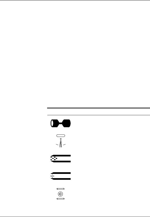
Symbols
Several symbols appear on the international front panel:
Symbol Indicates
Vessel Sealing
Regrasp
Macrobipolar
Bipolar
Memory
3-4 |
LigaSure Vessel Sealing Generator Service Manual |

Front Panel
Figure 3-2.
Vessel sealing intensity control, activation indicator, and regrasp indicator
Seal RF Activation Lamp
Illuminates with handswitch or footswitch activation.
Vessel Sealing Controls and Indicators
Vessel Sealing Intensity Display
A bar graph indicates the relative seal intensity setting.
Vessel Sealing Intensity Buttons
Press to increase the intensity.
Press to decrease the intensity.
Regrasp Indicator
Illuminates if the tissue is not sealed.
This may be due to:
•Tissue not responding to RF energy
•Tissue impedance is out of range
•Seal cycle was interrupted before the cycle was complete
•Maximum seal cycle time has been reached
Indicators, Controls, Receptacles and
LigaSure Vessel Sealing Generator Service Manual |
3-5 |
Front Panel
Figure 3-3.
Vessel sealing handset receptacle (purple)
Vessel Sealing Handset Receptacle (purple)
You can only connect a LigaSure vessel sealing instrument to this receptacle.
Connect a footswitching instrument with a multi-pin connector.
This receptacle is designed to accept a
Valleylab Smart Connector.
When the handset is correctly connected, the vessel sealing receptacle indicator illuminates green.
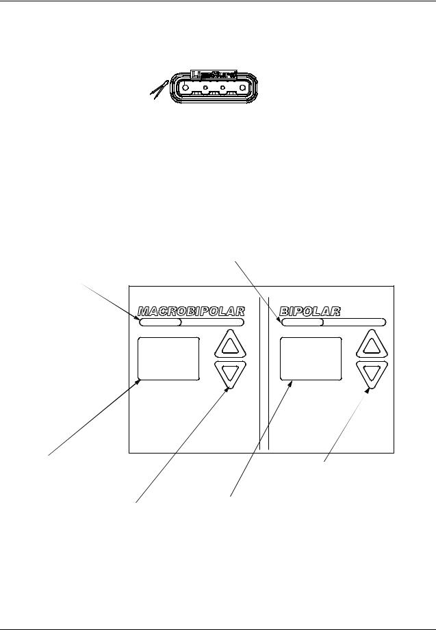
Bipolar Controls and Indicators
Figure 3-4.
Bipolar controls and indicators
Macrobipolar RF Activation Lamp
These lamps illuminate with handswitch or footswitch. activation.
Bipolar RF Activation Lamp
These lamps illuminate with handswitch or footswitch activation.
Macrobipolar Power Display
Shows the power setting in Watts for the Macrobipolar mode.
Macrobipolar Power Buttons
Press to increase the power.
Press to decrease the power.
Bipolar Power Buttons
Press to increase the power. Press to decrease the power.
Bipolar Power Display
Shows the power setting in Watts for the Bipolar mode.
3-6 |
LigaSure Vessel Sealing Generator Service Manual |

Front Panel
Bipolar Handset Receptacle (blue)
Figure 3-5.
Bipolar handset receptacle (blue)
You can connect either a footswitching or handswitching bipolar/macrobipolar instrument to this receptacle.
Connect a footswitching instrument with a two-pin connector.
or
Connect a handswitching instrument with a three-pin connector.
This receptacle is designed to accept a Valleylab Smart Connector or a Valleylab Smart Connector adapter. If the bipolar instrument you select does not have a Smart Connector, you must use the Valleylab Smart Connector adapter (p/n LS0500).
When the bipolar handset or Valleylab Smart Connector is correctly connected, the bipolar receptacle indicator light illuminates green.
Indicators, Controls, Receptacles and
LigaSure Vessel Sealing Generator Service Manual |
3-7 |
Rear Panel
Rear Panel
Figure 3-6.
Rear panel controls and receptacles
Vessel Sealing Footswitch
Receptacle (purple band)
Bipolar Footswitch
Receptacle (blue band)
Speaker |
|
|
|
|
|
|
|
|
|
|
|
|
|
|
|
|
|
|
|
|
|
|
|
|
|
|
|
Handle |
||||||||||||||||||||
|
|
|
|
|
|
|
|
|
|
|
|
|
|
|
|
|
|
|
|
|
|
|
|
|
|
|
|
|
|
|
|
|
|
|
|
|
|
|
|
|
|
|
|
|
|
|
|
|
|
|
|
|
|
|
|
|
|
|
|
|
|
|
|
|
|
|
|
|
|
|
|
|
|
|
|
|
|
|
|
|
|
|
|
|
|
|
|
|
|
|
|
|
|
|
|
|
|
|
|
|
|
|
|
|
|
|
|
|
|
|
|
|
|
|
|
|
|
|
|
|
|
|
|
|
|
|
|
|
|
|
|
|
|
|
|
|
|
|
|
|
|
|
|
|
|
|
|
|
|
|
|
|
|
|
|
|
|
|
|
|
|
|
|
|
|
|
|
|
|
|
|
|
|
|
|
|
|
|
|
|
|
|
|
|
|
|
|
|
|
|
|
|
|
|
|
|
|
|
|
|
|
|
|
|
|
|
|
|
|
|
|
|
|
|
|
|
|
|
|
|
|
|
|
|
|
|
|
|
|
|
|
|
|
|
|
|
|
|
|
|
|
|
|
|
|
|
|
|
|
|
|
|
|
|
|
|
|
|
|
|
|
|
|
|
|
|
|
|
|
|
|
|
|
|
|
|
|
|
|
|
|
|
|
|
|
|
|
|
|
|
|
|
|
|
|
|
|
|
|
|
|
|
|
|
|
|
|
|
|
|
|
|
|
|
|
|
|
|
|
|
|
|
|
|
|
|
|
|
|
|
|
|
|
|
|
|
|
|
|
|
|
|
|
|
|
|
|
|
|
|
|
|
|
|
|
|
|
|
|
|
|
|
|
|
|
|
|
|
|
|
|
|
|
|
|
|
|
|
|
|
|
|
|
|
|
|
|
|
|
|
|
|
|
|
|
|
|
|
|
|
|
|
|
|
|
|
|
|
|
|
|
|
|
|
|
|
|
|
|
|
|
|
|
|
|
|
|
|
|
|
|
|
|
|
|
|
|
|
|
|
|
|
|
|
|
|
|
|
|
|
|
|
|
|
|
|
|
|
|
|
|
|
|
|
|
|
|
|
|
|
|
|
|
|
|
|
|
|
|
|
|
|
|
|
|
|
|
|
|
|
|
|
|
|
|
|
|
|
|
|
|
|
|
|
|
|
|
|
|
|
|
|
|
|
|
|
|
|
|
|
|
|
|
|
|
|
|
|
|
|
|
|
|
|
|
|
|
|
|
|
|
|
|
|
|
|
|
|
|
|
|
|
|
|
|
|
|
|
|
|
|
|
|
|
|
|
|
|
|
|
|
|
|
|
|
|
|
|
|
|
|
|
|
|
|
|
|
|
|
|
|
|
|
|
|
|
|
|
|
|
|
|
|
|
|
|
|
|
|
|
|
|
|
|
|
|
|
|
|
|
|
|
|
|
|
|
|
|
|
|
|
|
|
|
|
|
|
|
|
|
|
|
|
|
|
|
|
|
|
|
|
|
|
|
|
|
|
|
|
|
|
|
|
|
|
|
|
|
|
|
|
|
|
|
|
|
|
|
|
|
|
|
|
|
|
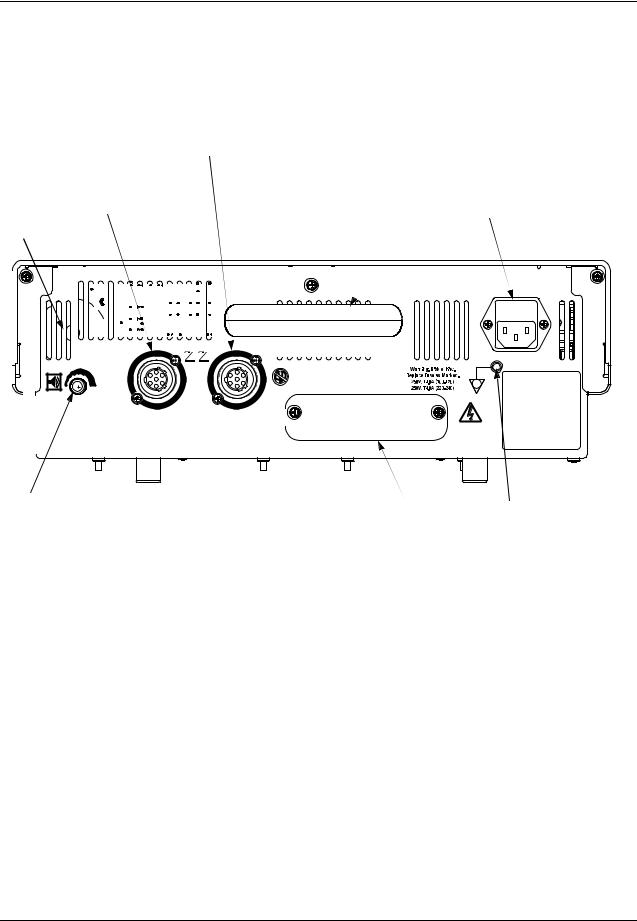
Power Entry Module
Contains a fuse drawer, with two fuses, and a receptacle for connecting the generator power cord.
Volume Knob |
Option Panel |
Grounding Lug |
|
To increase the volume, turn the knob clockwise. |
|||
|
Use this to connect the |
||
To decrease the volume, turn it counterclockwise. |
|
||
|
generator to earth ground. |
||
You cannot deactivate the activation tone or |
|
|
|
adjust the Regrasp indicator tone volume. |
|
|
3-8 |
LigaSure Vessel Sealing Generator Service Manual |
Rear Panel
Vessel Sealing Footswitch Receptacle (purple)
Figure 3-7.
Vessel sealing footswitch receptacle (purple)
Figure 3-8.
Bipolar footswitch receptacle (blue)
Connect either the two-pedal vessel sealing footswitch or the single-pedal vessel sealing footswitch to this receptacle.
Two Pedal Footswitch
The connected footswitch activates either vessel sealing or bipolar output for the LigaSure instrument that is connected to the Vessel Sealing Handset receptacle on the front panel.
Single Pedal Footswitch
The connected footswitch activates only the vessel sealing output for the LigaSure instrument that is connected to the Vessel Sealing Handset receptacle on the front panel
Bipolar Footswitch Receptacle (blue)
Connect the bipolar/macrobipolar footswitch when you connect a bipolar footswitching instrument to the generator.
Connect the two-pedal bipolar footswitch to this receptacle.
The connected footswitch activates bipolar or macrobipolar output for the bipolar instrument that is connected to the Bipolar handset receptacle on the front panel.
Indicators, Controls, Receptacles and
LigaSure Vessel Sealing Generator Service Manual |
3-9 |
Rear Panel
Option Panel
A removable plate on the rear panel covers a serial port, an RF (radio frequency) activation port, and an expansion port. To review the technical specifications for each port, refer to Chapter 4, Technical Specifications.
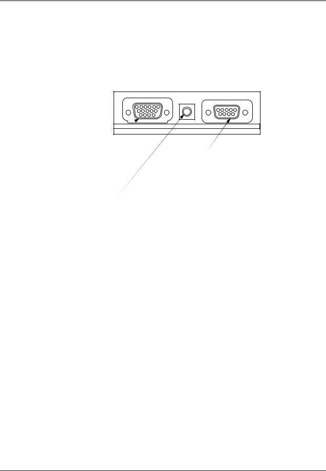
Figure 3-9.
The option panel
Expansion Port
Allows a connected device to receive information about RF output from the generator.
RF Activation Port
Serial Port
Allows connecting a computer to the generator to obtain information using the RS232 communications protocol.
Allows a connected device to receive information during RF activation of the generator, which can then generate a response. in the device.
3-10 |
LigaSure Vessel Sealing Generator Service Manual |
 Loading...