


User’s Guide
RapidVac™
Smoke Evacuator System

Foreword
This manual and the equipment it describes are for use only by qualified medical
professionals trained in the particular technique and surgical procedure to be performed.
It is intended as a guide for using the RapidVAc Smoke Evacuator only. Additional
users information is available in the RapidVac™ Smoke Evacuator Service
Manual.
Caution
Federal (USA) law restricts this device to sale by or on the order of a physician.
Equipment covered in this manual
RapidVac Smoke Evacuator—110 V and 220 V
Part Number: 1008878
Effective Date: May 2008
Trademark acknowledgements
RapidVac™ is a trademark of Valleylab. All trade names referenced are the
trademarks, registered trademarks, or products of their respective manufacturers.
Manufactured for:
Valleylab, a division of Tyco Healthcare Group LP
Boulder, Colorado 80301-3299 USA
European representative
Tyco Healthcare UK Ltd.
Gosport, PO13 0AS, UK
Device is compliant with the European Communities Council Directive 93/42/
EEC, Medical Device Directive.
Printed in USA
©2008 Valleylab. All rights reserved.
For information call
1-303-530-2300
Internet address
http://www.valleylab.com
ii RapidVac™ Smoke Evacuator User’s Guide

RapidVac™ Smoke Evacuator User’s Guide iii

Warranty
Valleylab, a division of Tyco Healthcare Group LP, warrants each product
manufactured by it to be free from defects in material and workmanship under
normal use and service for the period(s) set forth below. Valleylab’s obligation
under this warranty is limited to the repair or replacement, at its sole option, of
any product, or part thereof, which has been returned to it or its Distributor within
the applicable time period shown below after delivery of the product to the
original purchaser, and which examination discloses, to Valleylab’s satisfaction,
that the product is defective. This warranty does not apply to any product, or part
thereof, which has been repaired or altered outside Valleylab’s factory in a way so
as, in Valleylab’s judgment, to affect its stability or reliability, or which has been
subjected to misuse, neglect, or accident.
The warranty periods for Valleylab products are as follows:
Microwave Ablation Generator One year from date of shipment
Microwave Ablation Pump One year from date of shipment
Electrosurgical Generators One year from date of shipment
RFG-3C™ Plus Lesion Generator One year from date of shipment
LigaSure™ Vessel Sealing System One year from date of shipment
LigaSure™ Reusable Instruments One year from date of shipment
Mounting Fixtures (all models) One year from date of shipment
Footswitches (all models) One year from date of shipment
Force Argon™ Units One year from date of shipment
RapidVac Smoke Evacuator One year from date of shipment
LigaSure
Sterile Single Use Items Sterility only as stated on packaging
Patient Return Electrodes Shelf life only as stated on packaging
MWA Antennas Shelf life only as stated on packaging
™ Sterile Single Use Items
Sterility only as stated on packaging
This warranty is in lieu of all other warranties, express or implied, including
without limitation, the warranties of merchantability and fitness for a particular
purpose, and of all other obligations or liabilities on the part of Valleylab.
Valleylab neither assumes nor authorizes any other person to assume for it any
other liability in connection with the sale or use of any of Valleylab’s products.
Notwithstanding any other provision herein or in any other document or
communication, Valleylab’s liability with respect to this agreement and products
sold hereunder shall be limited to the aggregate purchase price for the goods sold
by Valleylab to the customer. There are no warranties which extend beyond the
terms hereof. Valleylab disclaims any liability hereunder or elsewhere in
connection with the sale of this product, for indirect or consequential damages.
iv RapidVac™ Smoke Evacuator User’s Guide

This warranty and the rights and obligations hereunder shall be construed under
and governed by the laws of the State of Colorado, USA. The sole forum for
resolving disputes arising under or relating in any way to this warranty is the
District Court of the County of Boulder, State of Colorado, USA.
Valleylab, its dealers, and representatives reserve the right to make changes in
equipment built and/or sold by them at any time without incurring any obligation
to make the same or similar changes on equipment previously built and/or sold by
them.
RapidVac™ Smoke Evacuator User’s Guide v

Conventions Used in this Guide
Warning
Indicates a potentially hazardous situation which, if not avoided, could result in
death or serious injury.
Caution
Indicates a hazardous situation which, if not avoided, may result in minor or
moderate injury.
Notice
Indicates a hazard that may result in product damage.
Important
Indicates an operating tip or maintenance suggestion.
vi RapidVac™ Smoke Evacuator User’s Guide

Table of Contents
Foreword................................................................................................................................................................... ii
Warranty ..................................................................................................................................................................iv
Conventions Used in this Guide .......................................................................................................................... vi
Chapter 1. Introducing the RapidVac Smoke Evacuator
Parts Shipped with the Smoke Evacuator........................................................................................................ 1-2
About the RapidVac Smoke Evacuator ............................................................................................................ 1-2
Features ....................................................................................................................................................... 1-3
RapidVac+ System.....................................................................................................................................1-3
Operating Modes ........................................................................................................................................1-3
Power............................................................................................................................................................1-4
Operating Parameters................................................................................................................................1-4
Transport and Storage...............................................................................................................................1-4
Patient and Operating Room Safety .................................................................................................................1-4
General.........................................................................................................................................................1-4
Maintenance................................................................................................................................................1-7
Chapter 2. Controls, Indicators, and Receptacles
Front Panel............................................................................................................................................................2-2
Power On/Off Switch..................................................................................................................................2-3
Air Flow Controls ........................................................................................................................................2-3
Turbo Button................................................................................................................................................2-3
Filter Life Indicator ......................................................................................................................................2-4
RapidVac+ Button.......................................................................................................................................2-4
Footswitch Jack ..........................................................................................................................................2-4
Service Required Indicator........................................................................................................................2-4
Rear Panel ............................................................................................................................................................ 2-5
Power Cord Receptacle/Fuse Tray.......................................................................................................... 2-5
Remote Activator Jack...............................................................................................................................2-6
EPROM Jack (Covered) ............................................................................................................................ 2-6
Equipotential Grounding Lug ....................................................................................................................2-6
Chapter 3. Before Surgery
Periodic Inspection...............................................................................................................................................3-2
Initial Installation...................................................................................................................................................3-2
Checking the Smoke Evacuator ........................................................................................................................3-4
Checking the Remaining Filter Life.......................................................................................................... 3-4
Changing the Filter .....................................................................................................................................3-5
Testing the Airflow Controls...................................................................................................................... 3-5
Installing and Testing the Footswitch (optional) ....................................................................................3-6
Installing and Testing the Remote Switch Activator (optional)............................................................ 3-7
Installing and Testing the Generator Interlink Cable (optional)...........................................................3-8
Setting Up the Smoke Evacuator ......................................................................................................................3-9
After the initial installation, set up the smoke evacuator for use......................................................... 3-9
RapidVac Smoke Evacuator User’s Guide vii

Mounting the Smoke Evacuator...............................................................................................................3-9
Open Procedure—Evacuating Dry Smoke............................................................................................. 3-9
Open Procedure—Evacuating Smoke and Incidental Fluids............................................................ 3-10
Chapter 4. During Surgery
Initiating Airflow ....................................................................................................................................................4-2
Minimizing Noise.................................................................................................................................................. 4-2
Variables Affecting Airflow..................................................................................................................................4-3
Changing the Airflow ........................................................................................................................................... 4-3
Periodic Checks ...................................................................................................................................................4-3
Tubing .......................................................................................................................................................... 4-3
Sponge Guard.............................................................................................................................................4-3
Filter Life Indicator...................................................................................................................................... 4-3
Chapter 5. After Surgery
Preparing the RapidVac Smoke Evacuator for Reuse...................................................................................5-2
Removing the Tubing................................................................................................................................. 5-2
Cleaning the Smoke Evacuator......................................................................................................................... 5-2
Chapter 6. Troubleshooting
Inspecting the RapidVac Smoke Evacuator .................................................................................................... 6-2
Correcting Specific Malfunctions .......................................................................................................................6-2
Chapter 7. Maintenance and Repair
Routine Maintenance .......................................................................................................................................... 7-2
Checking the Power Cord ......................................................................................................................... 7-2
Removing the RapidVac Filter ................................................................................................................. 7-2
Responsibility of the Manufacturer....................................................................................................................7-2
Obtaining a Return Authorization Number....................................................................................................... 7-3
Returning the Smoke Evacuator for Service ................................................................................................... 7-3
Service Centers....................................................................................................................................................7-3
viii RapidVac Smoke Evacuator User’s Guide

Chapter
1Introducing the
RapidVac Smoke Evacuator
This section describes the clinical applications and features of the
RapidVac Smoke Evacuator.
1
Caution
Read all warnings, cautions, and instructions provided with this smoke evacuator
before using.
Read the instructions, warnings, and cautions provided with electrosurgical
accessories before using. Specific instructions are not included in this manual.
RapidVac™ Smoke Evacuator User’s Guide 1-1

Parts Shipped with the Smoke Evacuator
Parts Shipped with the Smoke Evacuator
When unpacking the smoke evacuator, verify that the following parts are
included:
• Power cord
• User’s guide and service manual
• Quick reference card
Upon initial receipt, inspect the smoke evacuator for dents, cracks, or damage that
may have occurred during shipment. If damage is present, notify the freight
carrier for assessment.
Additional items are available from Valleylab:
• Replacement RapidVac Filters
• RapidVac Footswitch
• RapidVac Remote Switch Activator
• Generator Interlink Cable
• Laparoscopic Smoke Evacuator Tubing Kit
• Hoses, tubing, adapters, wands and other accessories
About the RapidVac Smoke Evacuator
The RapidVac Smoke Evacuator captures particulates and adsorbs gases from
surgical smoke. The smoke evacuator is specifically designed to improve
visibility and reduce potential health hazards associated with surgical smoke. It
can be used in both open and laparoscopic procedures.
The RapidVac Smoke Evacuator is designed with a high suction, high flow rate
centrifugal action pump. The ultra-quiet motor is used to draw the smoke from the
surgical site through the vacuum tubing and into the system where it is processed
by a series of filters. A single disposable filter is used to simplify the installation
and removal during filter changes. The filter is completely enclosed to protect the
healthcare personnel from potential contamination during filter changes.
One SEA3700 Filter contains four filtration stages to capture the smoke plume:
• Stage 1 - A prefilter that traps and removes gross particulate and
incidental fluid.
• Stage 2 - An ULPA grade (Ultra Low Penetration Air) patented filter
captures particulates and micro-organisms down to 0.1 µm at 99.9995%
efficiency.
• Stage 3 - The highest grade virgin activated carbon, designed specifically
for Valleylab for the removal and adsorption of odors and toxic gases
produced by burning tissue. These harmful gases may constitute a health
hazard to healthcare professionals who are subjected to prolonged
exposure. The activated carbon used in the smoke evacuation system
preferentially removes toxic organic gases (rather than water vapor) and
provides optimal odor removal.
1-2 RapidVac™ Smoke Evacuator User’s Guide

About the RapidVac Smoke Evacuator
• Stage 4 - An expanded foam used to trap activated carbon fines from
migrating out of the filter.
Features
RapidVac Smoke Evacuator features include:
• Filter-life monitoring for its four-stage, 25-five hour filter
• Standby, RapidVac+, footswitch, or continuous operation modes
• Quiet operation
• Adjustable flow
• Compatibility with all Valleylab electrosurgery pencils and generators
RapidVac+ System
The RapidVac Smoke Evacuator incorporates The RapidVac+ mode which
controls the flow of the smoke evacuator when using a Valleylab electrosurgical
pencil. When the electrosurgical pencil is activated, the smoke evacuator operates
in the preselected flow setting. When the pencil is deactivated, the air flow
reduces to a low-flow purge setting.
Introducing the RapidVac
Smoke Evacuator
Two Valleylab accessories link the electrosurgical generator and smoke evacuator
to enable the RapidVac+ mode:
• RapidVac Remote Switch Activator
• Generator Interlink Cable
Operating Modes
Four operating modes are available: standby, footswitch, RapidVac+, and
continuous.
• Standby mode powers up the unit without activating the motor or vacuum
flow.
• Footswitch mode is used to turn the smoke evacuator on or off with the
optional footswitch pedal.
• RapidVac+ mode is used to control the vacuum flow simultaneously with
activation of an electrosurgical pencil. This mode is controlled with the
optional generator interlink or electrosurgery sensor.
• Continuous mode is used to operate the smoke evacuator using continuous
air flow.
RapidVac™ Smoke Evacuator User’s Guide 1-3

Patient and Operating Room Safety
Power
This unit is equipped from the factory with either a 110 VAC hospital grade
NEMA 5-15 power cord or a 220 VAC CEE7/7 power cord. Should the AC
power cord need replacing to match another plug configuration, the replacement
plug/cable/receptacle configuration must meet or exceed the following
specifications.
100-120 VAC
Cable - SJT16/3, IEC color code, maximum length 15 ft. (5m)
Plug - minimum 10A 125 VAC
Unit receptacle - IEC female, minimum 10A 125 VAC
220-240 VAC
Cable - H05VVF3G1.0 VDE, maximum length 15 ft. (5m)
Plug - minimum 6A 250 VAC
Unit receptacle - IEC female, minimum 6A 250 VAC
Operating Parameters
Ambient temperature range 10° C to 40° C (50° F to 104° F)
Relative humidity 30% to 75%, noncondensing
Transport and Storage
Ambient temperature range -34° C to 65° C (-29° F to 149° F)
Relative humidity 25% to 85%, noncondensing
Patient and Operating Room Safety
General
Warning
Only trained personnel are to operate the RapidVac Smoke Evacuator. Operators
should avail themselves of preclinical training, a review of pertinent literature, and
other appropriate education before attempting to use the RapidVac.
During initial set up, inspect the smoke evacuator for any damage that may have
been caused during shipping. If damaged, do not use or attempt to repair. Call
Valleylab for service assistance.
1-4 RapidVac™ Smoke Evacuator User’s Guide

Patient and Operating Room Safety
Warning
Inspect the smoke evacuator before each use. If there is evidence of damage, do
not use the smoke evacuator. Call Valleylab for service assistance.
The RapidVac Smoke Evacuator filter is a disposable component that captures
potentially hazardous particles. Handle used filters as you would any
biohazardous material. Dispose of used filters according to your local codes and
regulations, and follow your institutions procedures for disposal.
The smoke evacuation filter has a life of approximately 25 hours of use and
should not be used beyond the specified time. If the Replace Filter indicator
illuminates during operation, the smoke evacuator will continue to run until it is
turned off. Turning power off to the smoke evacuator will require replacement of
the filter before subsequent use.
Failure to change the filter accordingly may result in decreased efficiency in
smoke evacuation and contamination of the motor, vacuum pump, and sound
absorbing media within the smoke evacuator.
Do not operate this device in potentially explosive environments, such as in the
presence of flammable anesthetics.
Refer routine servicing to qualified biomedical technical personnel.
Use only with the power cord provided and always plug into a grounded outlet.
Introducing the RapidVac
Smoke Evacuator
Do not use two- or three-prong adapters with the smoke evacuator’s power
cords.
The power-cord assembly should be checked periodically for damaged insulation
or connectors. Do not use damaged cords.
Use of extension cords may result in fire hazards.
This device is not intended for the evacuation of fluid. If fluid is expected to be
aspirated to the smoke evacuation filter, a fluid collection device must be installed
with the vacuum hose assembly. Failure to install a fluid collection device could
cause filter blockage and electrical damage. Contact Valleylab Service for
additional information.
Do not connect a wet power cord to the wall receptacle.
If the smoke evacuator becomes wet, either from a leaking tube or from being
sprayed, unplug the smoke evacuator from the Mains outlet. Wipe dry or allow to
air dry before proceeding.
Connect the smoke evacuator power cord to a properly grounded receptacle.
Plug the power cord directly into the power receptacle without any adapter plugs.
Use of power plug adapters may result in electric shock.
Do not remove any covers or panels exposing the internal components of the
smoke evacuator. Refer to a Valleylab representative for service.
The smoke evacuator produces a strong vacuum. Adjust the airflow and the
position of the inlet end of the wand or tubing to prevent patient injury and to
prevent suction of surgical materials and surgical specimens.
RapidVac™ Smoke Evacuator User’s Guide 1-5

Patient and Operating Room Safety
Warning
If the smoke evacuator is activated while the airflow is set to a high speed, it may
produce a sudden, strong suction action. Check the airflow setting before
activating the smoke evacuator to prevent patient injury and to prevent suction of
surgical materials and surgical specimens.
Caution
Do not stack equipment on top of the smoke evacuator or place the smoke
evacuator on top of electrical equipment. These configurations are unstable and/
or do not allow for adequate cooling.
Use only Valleylab SEA3700 Filters in the RapidVac Smoke Evacuator. Filters
from other manufacturers may cause damage to the system, thereby voiding the
warranty.
Provide as much distance as possible between the smoke evacuator and other
electronic equipment (such as monitors). An activated smoke evacuator may
cause interference with them.
Read all warnings, cautions, and instructions provided with the RapidVac Smoke
Evacuator before using.
To maximize patient safety, the tubing or wand should not come in direct contact
with tissue. Otherwise, patient injury may result.
Do not block either the tubing or the filter. If either becomes occluded or
significantly restricted, the motor/blower may overheat and cause the unit to shut
down.
Care must be exercised in the installation of hoses, adapters and suction
canisters. Failure to follow the procedures outlined in this manual may result in
overheating of the motor and may void the unit warranty.
Notice
Using any unapproved filter or accessory with the smoke evacuator may cause
damage and will void the warranty.
The RapidVac Smoke Evacuator functions properly only when the ULPA filter is
correctly installed. If the filter is installed incorrectly, the amber Replace Filter
indicator flashes and the Service Required indicator is illuminated.
Fluids may damage the filters. When evacuating smoke and incidental fluids,
always use the appropriate tubing,
Connect the power cord to a wall receptacle having the correct voltage.
Otherwise, product damage will result.
Power line voltage below 100 VAC (110V SEA3690) and 200 VAC (220V
SEA3695) will significantly reduce airflow.
Connecting multiple lengths of tubing together may cause the smoke evacuator
to overheat.
1-6 RapidVac™ Smoke Evacuator User’s Guide

Patient and Operating Room Safety
Notice
The RapidVac Smoke Evacuator has been specially designed to fit on Valleylab
mounting carts only. Do not install the smoke evacuator on a cart other than a
Valleylab cart. Installing the smoke evacuator inside a cart with improper
ventilation may result in overheating or may adversely affect the stability of the
cart.
Periodically check the cart brackets that hold the smoke evacuator in place to
ensure that the screws are securely fastened.
Stacking the smoke evacuator on top of a generator may cause an unstable
condition and/or cause the smoke evacuator to overheat.
Do not use sterile accessory products if sterile packaging has been
compromised.
Maintenance
Warning
Always turn off and unplug the smoke evacuator before cleaning.
The ULPA filter captures potentially hazardous particles. Handle used filters as
you would any biohazardous material. Dispose of filters with other operative
waste materials according to the procedures for your institution.
Introducing the RapidVac
Smoke Evacuator
Do not reuse or resterilize any product labeled “DISPOSABLE” or “SINGLE
USE.” Doing so may result in cross contamination, injury to the patient or medical
staff, or equipment malfunction.
Caution
Inspect the smoke evacuator before each use. If there is evidence of damage, do
not use the smoke evacuator. Call Valleylab for service assistance.
Notice
Do not rub, touch, or clean the smoke evacuator with alcohol or caustic,
corrosive, or abrasive cleaning or disinfectant compounds, solvents, or other
materials that could scratch the control panel or damage the smoke evacuator.
Do not autoclave, pressure sterilize, or gas sterilize the smoke evacuator.
Keep the smoke evacuator away from liquids. Liquids that enter the smoke
evacuator will damage internal components.
RapidVac™ Smoke Evacuator User’s Guide 1-7

Patient and Operating Room Safety
1-8 RapidVac™ Smoke Evacuator User’s Guide

2Controls, Indicators, and
Receptacles
This chapter describes the front and rear panels on the smoke
evacuator, including all controls, indicators, receptacles, and ports.
Chapter
2
RapidVac™ Smoke Evacuator User’s Guide 2-1

Front Panel
Front Panel
RapidVac
+
-
Smoke Evacuator
1 Power On/Off switch
2 Air-flow indicators (LED)
3 Turbo button
4 Air-flow controls
5 Power on indicator (LED centered in fan symbol)
6 Filter life indicators (LED)
7 RapidVac+ button
8 Service required indicator (LED)
9 Footswitch jack
Air filter with tubing connectors
RapidVac
1/4"
6 mm
3/8"
10 mm
7/8"
22 mm
Smoke Evacuator Filter
2-2 RapidVac™ Smoke Evacuator User’s Guide

Front Panel
Caution
Connect accessories to the proper receptacle type. Otherwise, the smoke
evacuator may not function properly.
Accessory equipment connected to interfaces must be certified according to
IEC 60601-1-1. All configurations shall comply with the system standard
IEC 60601-1-1. The user is responsible for verifying that accessory equipment
connections comply with the system requirements of IEC 60601-1-1. If in doubt,
contact Valleylab.
The electronic system controls on the RapidVac Smoke Evacuator are easy to
understand and simple to use. The control panel contains power and suction
controls, LED indicators, and connectors.
Notice
Please be sure to read all instructions before installing accessories or operating
this equipment. Failure to do so may result in damage to the unit and/or personal
injury.
Controls, Indicators, and
Receptacles
Power On/Off Switch
The power switch that controls power to the RapidVac Smoke Evacuator is
located in the lower-left corner of the front panel. To power up the smoke
evacuator, place the power switch in the ON position ( l ). The smoke evacuator
starts in standby (system power is on with no suction). When the smoke evacuator
is on in standby, the LED in the center of the fan symbol on the front panel will
blink continually until a fan speed is selected.
Turn the system power off by placing the power switch in the OFF position ( O ).
Air Flow Controls
The level of suction is controlled by the air-flow controls. up-arrow ( ) and
down-arrow ( ) buttons. To start the fan from standby mode, press the uparrow button. It starts in the lowest suction setting indicated by a single
illuminated air-flow indicator.
The suction control should be set at the lowest practical setting to completely
remove the surgical smoke from the operative site. Pressing either the up- or
down-arrow buttons changes the current suction level by 20%. The selected level
of suction is displayed by the air-flow indicator LEDs.
Turbo Button
When increased smoke removal is necessary, the Turbo button may be pressed at
anytime to increase suction. Turbo mode effectively increases the airflow to 100%
suction flow to quickly remove the smoke plume from the surgical site.
RapidVac™ Smoke Evacuator User’s Guide 2-3

Front Panel
Filter Life Indicator
The filter life indicator provides a visual indication of the status of the life of the
filter in use. Each illuminated LED represents five hours of remaining time on the
25-hour filter. The RapidVac Smoke Evacuator tracks the time each filter has
been used allowing for an accurate display of remaining use for new or previously
used filters.
Reading the Filter Life Indicator
Install an unused RapidVac filter into the system. When the smoke evacuator is
on, all five of the filter life indicator LEDs illuminate indicating the new filter has
100% filter life. The indicator will regress through subsequent LEDs until the
final LED is illuminated indicating less than 5 hours of filter life remaining. At
one hour remaining, the LED changes to amber. When the time remaining reaches
30 minutes, the amber LED flashes slowly.
RapidVac+ Button
When the smoke evacuator is connected to a generator using the Generator
Interlink Cable, pressing the RapidVac+ button synchronizes the smoke
evacuator with the use of an electrosurgical pencil. When a pencil is activated, the
smoke evacuator activates to a preselected air flow level.
Footswitch Jack
A RapidVac Footswitch (SEA3745) is available for use with the RapidVac
Smoke Evacuator.
A footswitch may be added to any system by simply plugging it into the
footswitch jack on the front panel. The unit may be turned on or off by depressing
the footswitch pedal once for each operation. For footswitching operation, the
smoke evacuator should be on and the suction level to be activated from the
footswitch should be selected on the control panel.
Service Required Indicator
The motor powering the RapidVac Smoke Evacuator has two motor brushes that
require regular maintenance every 500 hours. When the smoke evacuator has
been in use for 500 hours, the Service Required Indicator illuminates. Replace the
motor brushes and reset the Service Required Indicator as directed in the
RapidVac Smoke Evacuator Service Manual.
2-4 RapidVac™ Smoke Evacuator User’s Guide
Rear Panel
250V, T10.0A-(100-120V)
250V, T8.0A-(220-240V)
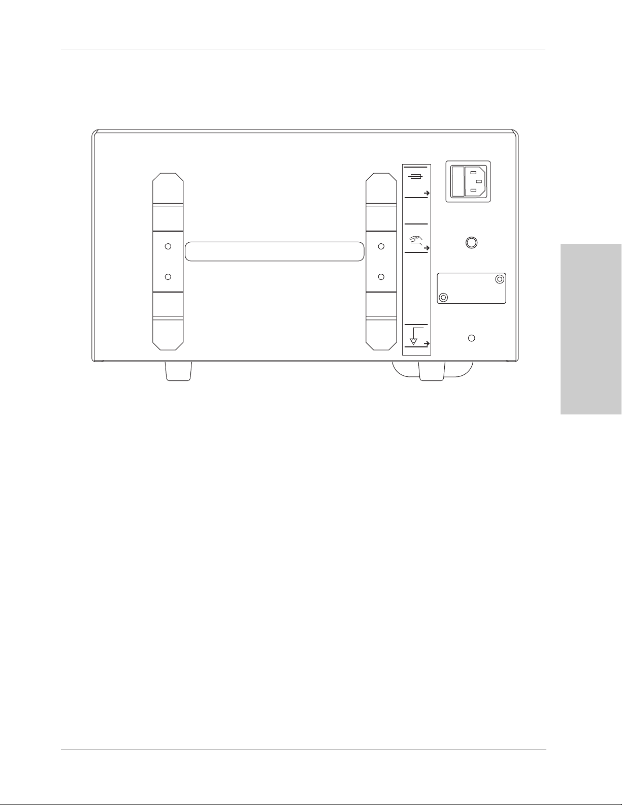
Rear Panel
1 Cord brackets
2 Carrying handle
3 Power-cord receptacle/fuse tray
4 Remote Activator jack
5 EPROM jack
6 Equipotential grounding lug
Remote
Activator
Controls, Indicators, and
Receptacles
Power Cord Receptacle/Fuse Tray
The cord receptacle provides power to the smoke evacuator using a removable
cord appropriate for regional power supplies. Cord can be wound on the cord
brackets to store with the smoke evacuator.
Two 10 AMP fuses in the 110V model (8 AMP for 220V) are located in a
removable tray adjacent to the cord receptacle. Fuses electrically protect the
system from damage and the operator from injury. If the system is overheated or if
there is an electrical surge in the electrical system, fuses will open and the system
will not operate. To re-start the system, unplug the power cord and replace the
fuses.
RapidVac™ Smoke Evacuator User’s Guide 2-5

Rear Panel
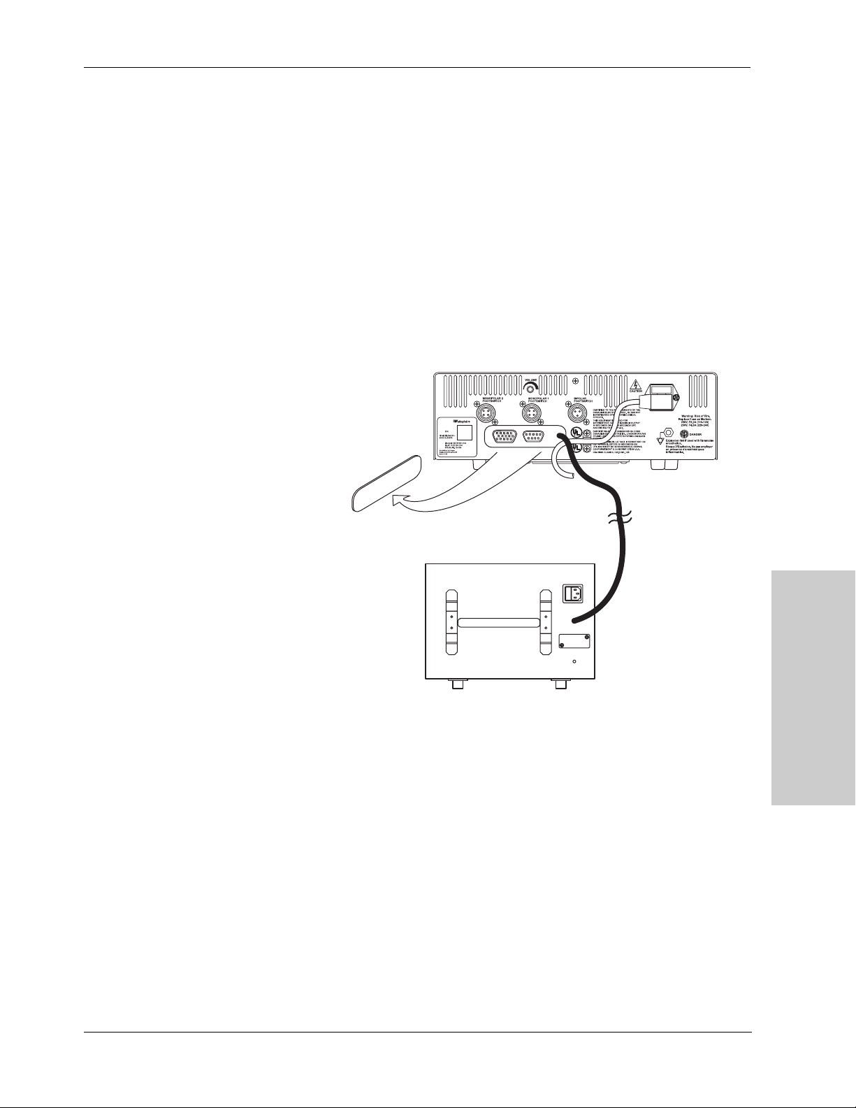
Remote Activator Jack
A Generator Interlink Cable (SEA3730) and Remote Switch Activator
(SEA3740) are available for the automatic remote activation of the RapidVac
Smoke Evacuator.
The Generator Interlink Cable is compatible with the Valleylab Force FX™,
ForceEZ™, and ForceTriad™ generators. It attaches to a generator’s RF
activation port and to the smoke evacuator’s Remote Activator jack. When the
generator is activated, the smoke evacuator automatically initiates the pre-set
suction.
The Remote Switch Activator is a programmable switch that plugs into the smoke
evacuator jack and is attached to an electrosurgical generator. The remote switch
is programmed to recognize the audible tones used by the generator. When the
tone for cut or coag sounds, the remote switch automatically initiates the pre-set
suction.
EPROM Jack (Covered)
The EPROM jack located under the secured cover is to be used only by qualified
Valleylab service technicians to update the smoke evacuator’s software.
Equipotential Grounding Lug
The equipotential grounding lug provides an alternate rout for electrical energy
back to ground when attached to an earth-ground cable.
2-6 RapidVac™ Smoke Evacuator User’s Guide

3Before Surgery
This section contains procedures for:
• Periodic Inspection
Chapter
3
• Initial installation
• Checking and testing the smoke evacuator prior to use
• Preparing for evacuation of dry smoke (open procedure)
• Preparing for evacuation of smoke and incidental fluids
(open procedure)
Caution
Read all warnings, cautions, and instructions provided with this smoke evacuator
before using.
Read the instructions, warnings, and cautions provided with smoke evacuator
accessories before using. Specific instructions are not included in this manual.
RapidVac™ Smoke Evacuator User’s Guide 3-1

Periodic Inspection
Periodic Inspection
Initial Installation
The RapidVac Smoke Evacuator should be visually inspected at least every year.
This inspection should include checks for:
• Damage to the power cord.
• Damage to the power plug.
• Tightness of the power plug.
• Proper mating, cleanliness and absence of damage to the filter inlet.
• Obvious external or internal damage to the system.
To prepare the RapidVac Smoke Evacuator for use, you must verify that the filter
is installed, connect the appropriate tubing, and check the performance of the
smoke evacuator indicators and controls.
Notice
Stacking the smoke evacuator on top of a generator may cause an unstable
condition and/or cause the smoke evacuator to overheat.
1. Inspect the power cord for any signs of visible damage. If it is in good
condition, plug the power cord into a grounded wall receptacle.
Warning
Connect the smoke evacuator power cord to a properly grounded, hospital grade
receptacle of the correct voltage. Plug the power cord directly into the power
receptacle without any extension cords and/or adapter plugs.
2. Insert a RapidVac SEA3700 filter into the square opening on the right side of
the smoke evacuator. Slide the filter into place until it is fully seated and the
locking mechanism clicks into place.
RapidVac
S
mo
k
e
E
v
a
c
ua
t
o
r
+
-
1/4"
6 mm
3/8"
10 mm
7/8"
22 mm
3. Turn on power to the smoke evacuator by pressing the on switch ( l ) located
on the front panel.
3-2 RapidVac™ Smoke Evacuator User’s Guide
Initial Installation
4. The smoke evacuator performs a self test. Verify that all LEDs are illuminated
during the test. When the test is complete, the RapidVac is placed in standby
mode signified by an illuminated power on LED within the fan symbol and no
active suction.
5. (Optional) Connect the RapidVac Remote Switch Activator (SEA3740) to the
Remote Switch jack on the back panel of the smoke evacuator. Use only the
RapidVac Remote Switch Activator. Other remote units are not compatible.
6. (Optional) Connect the Generator Interlink Cable (SEA3730) to the Remote
Switch jack on the back panel of the smoke evacuator. and to the rear panel of
the compatible Valleylab generator. Use only the Valleylab Interlink Cable.
Other cables may not be compatible.
7. (Optional) Connect the RapidVac Footswitch to the front panel of the smoke
evacuator. Use only Valleylab footswitches with the RapidVac Smoke
Evacuator.
Before Surgery
RapidVac™ Smoke Evacuator User’s Guide 3-3

Checking the Smoke Evacuator
Checking the Smoke Evacuator
Before each use, test the following smoke evacuator components to verify
performance:
• RapidVac ULPA filter
•Airflow controls
• Footswitch (as applicable)
• Remote switch activator (as applicable)
• Generator interlink (as applicable)
If the system does not respond as indicated below, refer to Chapter 6,
Troubleshooting.
Checking the Remaining Filter Life
RapidVac Smoke Evacuator filters have a use duration of 25 hours. As a filter is
used, information about the amount of time the individual filter has been used is
stored on the filter’s RFID tag. Whenever a new or previously used filter is
inserted, the smoke evacuator reads the stored information from the tag. The
remaining filter life is visually displayed by the corresponding number of filter
life indicators on the smoke evacuator front panel.
1. Turn on the smoke evacuator and insert a filter.
2. Check the filter life indicators on the front panel to verify the filter has ample
remaining time to complete a procedure.
Illuminated Filter Life
Remaining Use
Indicators
All 25 to 20 hours
4 20 to 15 hours
3 15 to 10 hours
2 10 to 5 hours
1 (green) 5 hours to 1 hour
1 (amber) less than 1 hour
1 (flashing amber) less than 30 minutes
Important
Replace the filter when indicated. Failure to replace the filter may reduce airflow
and compromise the efficiency of the filter.
3-4 RapidVac™ Smoke Evacuator User’s Guide

Checking the Smoke Evacuator
Changing the Filter
Warning
The ULPA filter captures potentially hazardous particles. Handle used filters as
you would any biohazardous material. Dispose of filters with other operative
waste materials according to the procedures for your institution.
1. Remove the filter by depressing the locking tab on the top edge of the filter
while pulling the filter straight out of the opening.
2. Dispose of the filter with other operative waste according to the procedures
for your institution.
3. Install a new filter in the smoke evacuator as described earlier in this section.
Testing the Airflow Controls
Warning
The smoke evacuator produces a strong vacuum. Properly adjust the airflow and
the position of the inlet end of the wand or tubing to prevent patient injury and to
prevent suction of surgical materials and surgical specimens.
You can start, stop, and change the vacuum airflow rate when the smoke
evacuator is on. Illuminated LEDs display the airflow setting. Each pressing of
the up-arrow ( ) or down-arrow ( ) increases or decreases suction by 20%.
There are five suction flow indicator LEDs that light in succession. Turbo Mode
illuminates the sixth LED next to the Turbo button.
Suction Flow Illuminated Suction Flow
Indicators
No suction (Standby Mode) None (LED at the center of the fan
symbol blinks)
20% motor speed 1
40% motor speed 2
60% motor speed 3
80% motor speed 4
100% motor speed 5
Turbo Mode (100%) 6
Before Surgery
1. Verify that the filter is installed properly.
2. Ensure that the power cord is plugged into a hospital grade power receptacle.
RapidVac™ Smoke Evacuator User’s Guide 3-5

Checking the Smoke Evacuator
3. Turn on the smoke evacuator by pressing the power on switch ( | ) on the
lower left of the front panel. The smoke evacuator powers up with the fan
motor off (standby mode). The LED in the center of the fan symbol blinks
indicating power is on.
4. Press the up-arrow ( ) button once to start suction at the lowest air-flow
setting.
5. Press the up-arrow ( ) button and pause briefly to progress to the next level
of suction. Verify that the level of suction noticeably increases with each
progression.
6. When all suction flow LEDs are lit steadily (100% motor speed), press the
down-arrow ( ) button repeatedly to regress through the settings to the
lowest setting.
Installing and Testing the Footswitch (optional)
Only use the Valleylab Footswitch with the smoke evacuator. Other footswitches
are not compatible.
1. Turn on the smoke evacuator.
2. Connect the footswitch cord to the footswitch jack on the front panel.
3. Turn on the airflow to any setting.
4. Press the footswitch once to turn off the airflow.
5. Press the footswitch again to activate the airflow.
3-6 RapidVac™ Smoke Evacuator User’s Guide

Checking the Smoke Evacuator
Installing and Testing the Remote Switch Activator
(optional)
Use the Valleylab Remote Switch Activator with any of Valleylab’s
electrosurgical pencils and generators.
1. Select a location on the generator near the speaker where the Remote Switch
Activator is to be mounted.
2. Clean the surface of the selected area with alcohol. Allow the alcohol to
evaporate.
3. Remove the backing from the gasket on the RSA.
4. Affix the RSA to the generator.
5. Plug the RSA connector into the Remote Activator jack located on the back
panel of the smoke evacuator.
6. Turn on the smoke evacuator and press the up-arrow ( ) button twice to
illuminate the first two air flow indicators (40% motor speed).
7. Set up the surgical pencil and generator as instructed in their user
documentation. If the generator’s audible-tone volume can be adjusted, set it
at 50%.
8. Initiate programming the Remote Switch Activator by pressing the
Program/Reset button continually for 10 seconds.
9. Set the generator to cut mode.
10. Activate the generator in cut mode until the smoke evacuator motor starts.
Depending on the generator, this may take up to 40 seconds.
11. When the smoke evacuator motor starts, deactivate the generator in cut mode.
Important
Do not activate the generator in cut mode again until the Remote Switch Activator
has been programmed in coag mode.
12. Set the generator to coag mode.
13. Activate the generator in coag mode until the smoke evacuator motor starts.
Depending on the generator, this may take up to 40 seconds.
14. When the smoke evacuator motor starts, deactivate the generator in coag
mode.
Important
If the generator has only one tone, program this same tone into the Remote
Switch Activator memory.
If both the cut and coag tones are not activating the smoke evacuator reprogram
the Remote Switch Activator. Disconnect the Remote Switch Activator from the
smoke evacuator, then re-connect. Repeat the programming instructions
beginning with step 8.
Before Surgery
The Remote Switch Activator is now programmed. Powering on and off the
RapidVac Smoke Evacuator is now controlled by the generator and Remote
Switch Activator.
RapidVac™ Smoke Evacuator User’s Guide 3-7

Checking the Smoke Evacuator
Important
If the attached smoke evacuator is to be disconnected from the generator, unplug
the Remote Switch Activator from the smoke evacuator. The Remote Switch
Activator should remain affixed to the generator to which it was programmed. The
RapidVac Smoke Evacuator cannot be operated manually or with a footswitch
while the Remote Switch Activator is plugged into the smoke evacuator.
If the Remote Switch Activator is moved to another generator, it must be
reprogrammed using the steps in this section.
Installing and Testing the Generator Interlink Cable
(optional)
The Generator Interlink Cable attaches to a RapidVac Smoke Evacuator and a
compatible Valleylab generator to synchronize smoke evacuation with the
activation of the generator. The cable is compatible with the Valleylab generator
models Force FX™, ForceEZ™, and ForceTriad™.
1. Turn power off and unplug the smoke evacuator and generator from the power
source.
2. Remove the metal cover plate in the center of the generator back panel to
access optional ports.
3. Plug the interlink cable into the generator RF Activation port.
4. Plug the interlink cable into the Remote Activator jack on the back panel of
the smoke evacuator.
5. Plug the generator and smoke evacuator into outlets of proper voltage.
6. Turn power on to both devices.
7. When the generator and smoke evacuator have completed their self tests, set
the level of suction to be used when the smoke evacuator is activated.
8. Press press the up-arrow ( ) button until reaching the desired pre-setting.
9. Press the RapidVac+ button.
The pre-set suction level is now selected. The smoke evacuator continues to run
and suction reduces to a minimal level. Use of the surgical pencil will
automatically activate the RapidVac to the pre-set suction level. When the pencil
is deactivated, the smoke evacuator will return to minimal suction.
3-8 RapidVac™ Smoke Evacuator User’s Guide

Setting Up the Smoke Evacuator
Warning
Connect the smoke evacuator power cord to a properly grounded receptacle.
Plug the power cord directly into the power receptacle without any adapter plugs.
Use of power plug adapters may result in electric shock.
Use of extension cords may result in fire hazards.
After the initial installation, set up the smoke evacuator for use.
Mounting the Smoke Evacuator
The smoke evacuator may be mounted in the following locations:
• The Valleylab UC8009 Universal Mounting Cart—primary, secondary, or
suspended shelf
• ForceTriad Cart FT900
• Boom systems
Setting Up the Smoke Evacuator
• Stable, flat surfaces
This section describes how to set up for the following procedures:
• Open procedure—evacuating dry smoke
• Open procedure—evacuating smoke and incidental fluids
Open Procedure—Evacuating Dry Smoke
Notice
Connecting multiple lengths of tubing together may cause the smoke evacuator
to overheat.
1. Verify the installed filter has enough available filter life to complete the
procedure.
2. Connect your choice of tubing to the corresponding filter tubing connection.
Notice
Do not connect more than one set of tubing to the smoke evacuator filter at one
time. Suction levels and air flow will be adversely affected.
Before Surgery
RapidVac™ Smoke Evacuator User’s Guide 3-9

Setting Up the Smoke Evacuator
Open Procedure—Evacuating Smoke and Incidental
Fluids
The primary function of the smoke evacuator is to evacuate surgical smoke. A
fluid canister is recommended to prevent the filters from getting wet when
evacuating smoke that may contain incidental fluids.
Notice
Fluids may damage the filters. When evacuating smoke and incidental fluids,
always use the appropriate tubing and fluid canister.
Check the fluid level in the canister frequently during surgery. If the fluid canister
overfills, smoke evacuator damage will result.
Connecting multiple lengths of tubing together may cause the smoke evacuator
to overheat.
1. Verify the installed filter has enough available filter life to complete the
procedure.
2. Insert a fluid canister in-line with the smoke evacuator tubing.
3-10 RapidVac™ Smoke Evacuator User’s Guide

3During Surgery
Chapter
4
This chapter covers the following topics:
• Minimizing airflow noise
• Changing and adjusting airflow
• Checking the tubing
• Checking the prefilter
• Checking the sponge guard
RapidVac™ Smoke Evacuator User’s Guide 4-1

Initiating Airflow
Initiating Airflow
Warning
The smoke evacuator produces a strong vacuum. Adjust the airflow and the
position of the inlet end of the wand or tubing to prevent patient injury and to
prevent suction of surgical materials and surgical specimens.
If the smoke evacuator is activated while the airflow is set to a high speed, it may
produce a sudden, strong suction action. Check the airflow setting before
activating the smoke evacuator to prevent patient injury and to prevent suction of
surgical materials and surgical specimens.
The smoke evacuation filter has a life of approximately 25 hours of use and
should not be used beyond the specified time. If the Replace Filter indicator
illuminates during operation, the smoke evacuator will continue to run until it is
turned off. Turning power off to the smoke evacuator will require replacement of
the filter before subsequent use.
This device is not intended for the evacuation of fluid. If fluid is expected to be
aspirated to the smoke evacuation filter, a fluid collection device must be installed
with the vacuum hose assembly. Failure to install a fluid collection device could
cause filter blockage and electrical damage. Contact Valleylab Service for
additional information.
Minimizing Noise
Caution
To maximize patient safety, the tubing or wand should not come in direct contact
with tissue. Otherwise, patient injury may result.
1. Verify that all tubing is connected.
2. Turn on the smoke evacuator by pressing the power on switch ( | ) on the front
panel. The smoke evacuator powers up with the fan motor off. The smoke
evacuator is in standby mode which is indicated by a blinking LED in the
center of the fan symbol.
3. Press the up-arrow ( ) button once to start suction at the lowest air-flow
setting.
The higher the power setting, the greater the noise. Minimize noise by using a
lower power setting. Effectiveness of a lower power setting can be maximized by
using a larger diameter tubing and/or positioning the tubing closer to the source of
smoke.
4-2 RapidVac™ Smoke Evacuator User’s Guide

Variables Affecting Airflow
The following factors may affect airflow:
• Diameter of the tubing—with larger diameter tubing, airflow improves
• Airflow settings
• Attachments
Changing the Airflow
You can change the airflow while the smoke evacuator is in use.
1. Adjust the air flow by pressing the up-arrow ( ) to increase or the down-
arrow ( ) button to decrease.
2. Verify that the indicator illuminates for the speed setting you selected.
Periodic Checks
Variables Affecting Airflow
During surgery periodically check the accessories described below.
Tubing
Check for clogged, occluded, or kinked tubing during surgery.
Sponge Guard
If a sponge guard is in use, ensure it is fully attached to the sterile tubing to
prevent suction of surgical materials.
Filter Life Indicator
Monitor the remaining life of the filter by viewing the Filter Life Indicator LEDs
on the smoke evacuator front panel.
During Surgery
RapidVac™ Smoke Evacuator User’s Guide 4-3

Periodic Checks
4-4 RapidVac™ Smoke Evacuator User’s Guide

3After Surgery
This chapter covers the following topics:
• Preparing the smoke evacuator for reuse
• Cleaning the smoke evacuator
Chapter
5
RapidVac™ Smoke Evacuator User’s Guide 5-1

Preparing the RapidVac Smoke Evacuator for Reuse
Preparing the RapidVac Smoke Evacuator for Reuse
After surgery, prepare the smoke evacuator for reuse by performing the following
procedures:
• Remove the tubing
• Clean the smoke evacuator
Caution
Do not reuse or resterilize accessories labeled “disposable” or “single use only.”
Removing the Tubing
Warning
The tubing and filter capture potentially hazardous particles. When removed,
handle as you would any biohazardous material. Dispose of these items with
other operative waste materials according to the procedures for your institution.
1. Press the power switch (O) on the front panel to turn off the smoke evacuator.
2. If applicable, disconnect the tubing from any reusable instrument that will not
be discarded with the tubing.
3. Disconnect the tubing from the smoke evacuator.
Cleaning the Smoke Evacuator
Warning
Always turn off and unplug the smoke evacuator before cleaning.
The tubing and filter capture potentially hazardous particles. When removed,
handle as you would any biohazardous material. Dispose of these items with
other operative waste materials according to the procedures for your institution.
Wear appropriate protective gear when cleaning the filter ports and covering flap
to avoid coming in contact with incidental contaminants on these surfaces.
Notice
Do not rub, touch, or clean the smoke evacuator with alcohol or caustic, corrosive
or abrasive cleaning or disinfectant compounds, solvents, or other materials that
could scratch the control panel or damage the smoke evacuator.
Do not autoclave, pressure sterilize, or gas sterilize the smoke evacuator.
Keep the smoke evacuator away from liquids. Liquids that enter the smoke
evacuator will damage internal components. Do not spray liquid cleaner into the
filter ports.
1. Ensure that the power switch on the front panel is off (O).
2. Disconnect the power cord from the wall receptacle.
5-2 RapidVac™ Smoke Evacuator User’s Guide

Cleaning the Smoke Evacuator
3. Disconnect tubing as directed in the previous section.
4. Thoroughly wipe all external surfaces with a mild detergent or disinfectant.
5. Thoroughly clean both sides of the flap covering the filter ports. Do not spray
liquid cleaner into the filter ports.
6. Clean the surface around the filter ports. Do not spray liquid cleaner into the
filter ports. Follow procedures approved by your institution, or use a validated
infection-control procedure.
Warning
Wear protective gloves when cleaning around filter ports. Do not place fingers
into ports or touch the internal surface of the ULPA filter. Contaminants may be
present.
7. Ensure the smoke evacuator is completely dry before use.
8. Reconnect the power cord to the wall receptacle.
After Surgery
RapidVac™ Smoke Evacuator User’s Guide 5-3

Cleaning the Smoke Evacuator
5-4 RapidVac™ Smoke Evacuator User’s Guide

9Troubleshooting
This chapter describes solutions to problems that may occur when
operating the smoke evacuator.
If the smoke evacuator is not functioning properly, use the
information in this section to help identify and correct the
Chapter
6
malfunction.
RapidVac™ Smoke Evacuator User’s Guide 6-1

Inspecting the RapidVac Smoke Evacuator
Inspecting the RapidVac Smoke Evacuator
If there is a problem with the operation of the smoke evacuator, inspect the unit
for obvious conditions that can cause a malfunction:
• Check for visible signs of damage
• Verify the connections of all cables and tubing
• Verify proper filter installation
• Verify that the power switch is on and the power-on indicator LED in the
center of the fan symbol is blinking.
• Check the filter life indicators to ensure the filter has available filter time
remaining.
Correcting Specific Malfunctions
If a solution to the problem is not readily apparent, use the following table to help
identify and correct specific malfunctions. After you correct the malfunction,
verify that the smoke evacuator is in proper working order.
Situation Possible Cause Recommended Action
Smoke evacuator is on but there is
minimal or no vacuum or airflow at
the wand or tubing
Smoke evacuator does not adsorb
odors
Smoke evacuator does not
operate
Improperly installed ULPA filter Ensure the ULPA filter is properly
installed. Reposition if necessary.
Clogged tubing Unclog/replace the tubing.
Clogged ULPA filter Replace the filter.
Obstructed or malfunctioning motor
and/or blower
Charcoal component of the filter has
expired
Disconnected or faulty power cord Check and correct the power cord
No power from wall receptacle (power
cord is connected to wall receptacle,
but Mode Indicator is not illuminated)
Power switch on the front panel is off
(
O)
Contact Valleylab service for
assistance.
Replace the filter.
connections. Check the cord for
damage. Replace cord if needed.
Check the power at the wall
receptacle. Connect power cord to a
functional wall receptacle.
Turn the power switch on (|).
Fuses damaged Check the fuses to see if they have
burned through from being over
loaded or otherwise damaged.
Replace fuses if needed.
6-2 RapidVac™ Smoke Evacuator User’s Guide

Correcting Specific Malfunctions
Situation Possible Cause Recommended Action
Footswitch does not activate
smoke evacuator when Footswitch
mode is selected
Indicator LEDs do not illuminate No electrical power Refer to electrical utility maintenance.
Motor does not run, but Power On
LED illuminates
Improperly connected footswitch Check that the footswitch is securely
connected at the front of the smoke
evacuator.
Malfunctioning footswitch Replace the footswitch.
Incorrect footswitch connected to the
smoke evacuator
Filter incorrectly installed Reinstall the filter. Ensure that the
Malfunction in the smoke evacuator Contact Valleylab service.
Fuses damaged Check the fuses to see if they have
Malfunction in the smoke evacuator Contact Valleylab service.
Filter incorrectly installed Reinstall the filter. Ensure the filter is
Connect the RapidVac Footswitch
(SEA3745) to the smoke evacuator.
filter is fully seated in the smoke
evacuator and the securing tab locks
into place.
burned through from being over
loaded or otherwise damaged.
Replace fuses if needed.
fully seated in the smoke evacuator
and the securing tab locks into place.
Troubleshooting
ESU remote does not activate
when RapidVac mode is selected
Malfunction in smoke evacuator Contact Valleylab service.
Generator interlink cable incorrectly
installed
Remote Switch Activator incorrectly
installed
ULPA filter incorrectly installed Reinstall the filter. Ensure the filter is
Ensure the generator interlink is
properly connected to the rear panel
of the smoke evacuator and the
Valleylab generator.
Ensure the Remote Switch Activator
is connected to the rear of the smoke
evacuator.
or
Check the ESU pencil lead installation
on the electrosurgery sensor bobbin.
fully seated in the smoke evacuator
and the securing tab locks into place.
RapidVac™ Smoke Evacuator User’s Guide 6-3

Correcting Specific Malfunctions
6-4 RapidVac™ Smoke Evacuator User’s Guide

10Maintenance and Repair
Chapter
7
Refer to this chapter for information on:
• Routine maintenance
• The manufacturer’s responsibility
• Returning the smoke evacuator for service
• Service centers
RapidVac™ Smoke Evacuator User’s Guide 7-1

Routine Maintenance
Routine Maintenance
The RapidVac Smoke Evacuator requires very little maintenance. Periodically,
you must check the power cord and replace the filter. Periodic inspections and
performance tests are recommended by a qualified biomedical technician to
ensure safe and efficient operation.
Checking the Power Cord
Inspect the power cord each time you use the smoke evacuator, or at intervals
recommended by your institution. Make sure the power cord is in good working
condition, without exposed wires, cracks, or frayed areas.
Removing the RapidVac Filter
The filter removes odorous gases and submicron particles from surgical smoke.
Important
If the Replace Filter indicator illuminates, remove and replace the filter. Failure to
do so may reduce airflow and compromise the efficiency of the filter.
Warning
The ULPA filter captures potentially hazardous particles. Handle used filters as
you would any biohazardous material. Dispose of filters with other operative
waste materials according to the procedures for your institution.
1. Ensure that the smoke evacuator power switch on the front panel is off (O).
2. Depress the locking tab on the top edge of the filter and pull straight out of the
smoke evacuator.
3. Dispose of the filter with other operative waste materials according to the
procedures for your institution.
Responsibility of the Manufacturer
Valleylab is responsible for the safety, reliability, and performance of the smoke
evacuator only under the following circumstances:
• Installation and setup procedures in this manual are followed.
• Readjustments, modifications, or repairs to the unit are carried out by persons
authorized by Valleylab.
• The electrical installation of the relevant room complies with local codes and
regulatory requirements, such as UL.
• The accessories are used in accordance with the Valleylab instructions for
use.
For warranty information, refer to the Warranty at the beginning of this guide.
7-2 RapidVac™ Smoke Evacuator User’s Guide

Obtaining a Return Authorization Number
Obtaining a Return Authorization Number
Notice
For repairs, return the smoke evacuator to Valleylab.
Before you return the smoke evacuator, call the Valleylab Customer Service
Department (1-800-255-8522) for a Return Authorization Number or call your
Valleylab Representative for assistance.
Have the following information ready when you call:
• Hospital/clinic name/customer number
• Telephone number
• Department/address, city, state, and zip code
• Model number
• Serial number
• Description of the problem
Returning the Smoke Evacuator for Service
Follow this procedure when returning the smoke evacuator for service. Service
center information is provided below.
1. Remove the filter and any attached tubing and fluid container.
Warning
The ULPA filter captures potentially hazardous particles. Handle used filters as
you would any biohazardous material. Dispose of filters with other operative
waste materials according to the procedures for your institution.
2. Clean the smoke evacuator thoroughly. Follow the procedures approved by
your institution or use a validated infection control procedure.
3. Attach a tag to the smoke evacuator that includes the Return Authorization
Number and the information listed above (i.e., hospital, phone number, etc.).
4. Be sure the smoke evacuator is completely dry. Then, package the smoke
evacuator in its original shipping container, if available.
5. When you receive the Return Authorization Number, ship the smoke
evacuator prepaid according to Valleylab's instructions.
Maintenance and Repair
Service Centers
For a complete list of service centers worldwide, please refer to the Valleylab
website:
http://www.valleylab.com/valleylab/international/service-world.html
RapidVac™ Smoke Evacuator User’s Guide 7-3

Service Centers
7-4 RapidVac™ Smoke Evacuator User’s Guide

AAccessories
The accessories listed in this chapter are recommended for use
with the RapidVac Smoke Evacuator. Accessories can be ordered
through your Valleylab Sales Representative.
Product Catalog No
Chapter
8
RapidVac Filter SEA3700
Tubing, 6 mm x 3 m (1/4 in x 10 ft), sterile SEA3705
Tubing, 10 mm x 3 m (3/8 in x 10 ft), sterile SEA3710
Tubing with Sponge Guard, 2 cm x 3 m (7/8 in x 10 ft), sterile SEA3715
Laparoscopic Tubing Kit with Valve SEA3720
Wand, Laser Resistant, 2 cm x 20 cm (7/8 in x 8 in) SEA3725
Generator Interlink Cable SEA3730
AccuVac Attachment with Tubing, 10 mm x 3 m (3/8 in x 10 ft) SEA3735
RapidVac Remote Switch Activator SEA3740
RapidVac Footswitch SEA3745
RapidVac™ Smoke Evacuator User’s Guide 8-1
8-2 RapidVac™ Smoke Evacuator User’s Guide
 Loading...