

Page 1
Title: Electrosurgical Generator Date: 2-6-2012
By: Valley Lab
File = esu-SSE2-3.doc
DISCLAIMER: THIS PROCEDURE PROVIDED "AS IS" AND
WITH POSSIBLE FAULTS. USER MUST VERIFY BEFORE USE.
NEITHER PROVIDER NOR WEBSITE ASSUMES ANY
RESPONSIBILITY FOR ITS USE.
1. General
Applies to Valleylab models SSE2K, SSE3 models.
2. Reference Documents
Valley Lab Maintenance Notes - see Appendix.
Valley Lab SSE3 “Complete Instruction Manual”
3. Tools / Fixtures / Labels
Electrosurgical Analyzer: ex: Dempsey 443.
Insulated wire set terminated with banana plugs.
Hand Control Pencil, footswitch.
Safety Tester
4. Basic PM Procedure
4.1. Inspection
Check unit for any damage, especially the front
connectors, the power cord and the footswitch with
its cable.
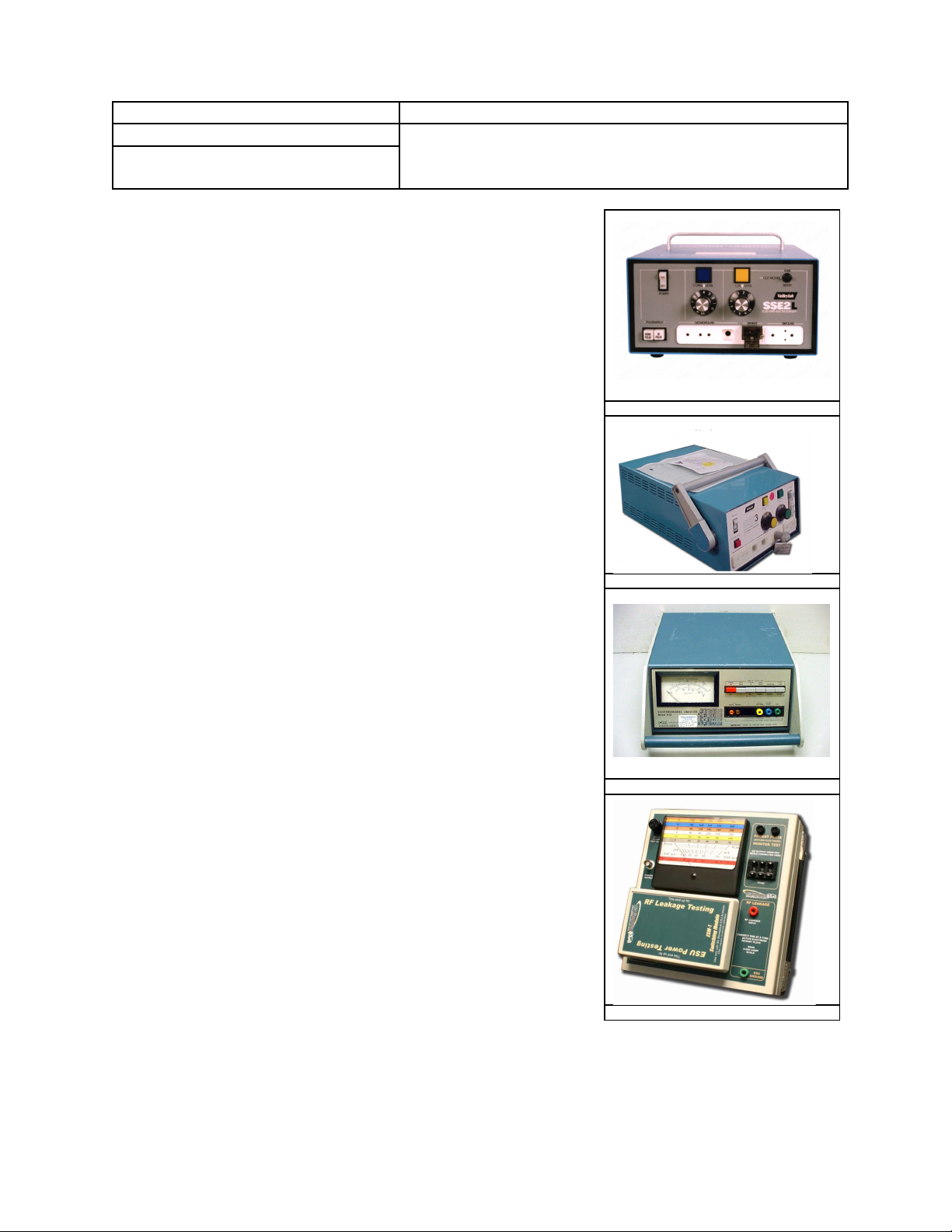
SSE2 ESU
SSE3 ESU
4.2. With no accessories plugged in, turn on unit. For the
SSE2, either the monopolar or bipolar lamp will
illuminate; press in the light switch that is off; it
should come on. For the SSE3, include the extra
mode lamps.
4.3. Setup
Connect analyzer to ESU using a handcontrol pencil;
wire the pencil chuck to the analyzer active (this
simultaneously will check handcontrol sense
circuits.) Connect a banana type lead between the
generator’s patient jack over to the same on the
analyzer. Set analyzer load to 300 ohms if available.
Press in the monopolar switch-lamp. Set the Blend
switch to pure cut.
4.4. Cut Mode
With both dials at zero, key the unit in Cut mode, and
note audible tone. The cut lamp will not illuminate until power is turned up past
approximately Dial = 1. Gradually turn power to max dial and note power into
analyzer. Refer to table for acceptable results. For reference, wattages at other loads
are listed.
DEMPSEY 443 ANALYZER
BC GROUP ESU-2000A ANALYZER
Page 2

4.5. Blend Mode
For each of three blend modes (SSE3 only), repeat the protocol for Cut, and note the
max dial output power in the table below.
4.6. Coag Mode
With both dials at zero, key the unit in Coag mode, and note distinct audible tone. The
coag lamp not illuminate until power is turned past approximately Dial = 1.
Gradually turn power to max dial and note power into analyzer. Refer to table for
acceptable results. For reference, wattages at other loads are listed.
4.7. Bipolar Mode
Press in the bipolar switch/lamp. Put Cut mode selector in Pure Cut. Connect the
analyzer to the two outside socket pins of the generator’s bipolar output connector.
Set analyzer load to 100 or 125 ohms. With both dials at zero, use the footswitch to
key the unit in Cut mode, and note distinct audible tone. Gradually turn power to max
dial and note power into analyzer. Refer to table for acceptable results.
Repeat, but using the coag side of footswitch. Refer to table for acceptable results.
POWER OUTPUTS FOR VARIOUS LOAD @ Max Dial*
MODE/LOAD R=500 R=300 R = 125 R=100
Cut 210 300 +/- 10% 270
Coag 110 115 +/- 10% 100
Blend 1
Blend 2 200
Blend 3 200
Listed blend
wattages are from
the SSE3 manual.
250
Bipolar Cut NA NA 55 60
Bipolar Coag NA NA 22 25
* Note: The wattage levels at 300 ohms are listed in SSE3 manual; powers at other loads
were derived from the published impedance curves of the Force series generators.
4.8. Verify volume adjust on back of unit.
4.9. Using the safety tester, check that line leakage with ground open is less than 50 uA.
4.10. Using the safety tester, check that ground lead resistance is less than .15 ohms.
4.11. REM – these units do not have the REM pad sensing feature.
5. Extended PM Procedure
Page 3

5.1 RF Leakage -- ESU analyzers read RMS current, and when appropriately connected,
can display RF leakage. Limits are below. RF leakage is an infrequent field check but
should not be overlooked for older equipment.
The standard IEC 60601-2-2, particular requirements for the safety of high frequency
surgical equipment, limits this parameter to a maximum of 4.5 W measured on a 200 Ω
non-inductive resistor for monopolar applications (150mA in this case).
APPENDIX
Repair Note: A common problem over time is lamp failure inside the various indicators. To get access to the small 24-28
volt lamps, squeeze the lamp indicator outer housing to remove.
In resource limited installations where analyzers and RF ammeters are unavailable, the technician can resort to connecting
three 100 watt (120 volt version) light bulbs in series to simulate a 100 – 300 ohm load. At low brightness levels, the
filament resistance is much lower than at full brightness; thus this method provides only a minimal qualitative check of
generator output.
The following notes from Valleylab are included because their testing philosophy prefers measuring RF current into a
known load and computing power via P = I2*R.
Usually bi-polar mode is tested at 100 ohms load, cut mode at 300 ohms and coagulation mode at 500 ohms. Measure the
current, not the watts. RF power output circuitry is 1 to 6 N channel MOSFET’s in parallel. With age and thermal damage,
they begin to fail and the output voltage drops. Circuitry compensates by increasing the current thru the MOSFET’s. Current
times voltage equals wattage. Measuring wattage will not detect the drop in voltage, but measuring current will detect the
voltage drop. Valleylab specifically states to test for current under specified load.
Bipolar output test (page 5-18)
1.Set analyzer load resistance to 100 ohms.
2.Set bipolar power to 10.
3.Press footswitch and measure current in all 3 modes. (Current delivered should
be 315 mA +/- 24 mA rms)
Cut mode output test (page 5-19)
1. Set the analyzer load resistance to 300 ohms.
2. Set CUT power to 75 watts.
3. Press CUT footswitch and measure current in the Pure, Low & Blend modes. (Current
delivered should be 499 mA +/- 38 mA.)
4. Repeat this test on the MONOPOLAR 2 using a hand piece.
Coag output test ( page 5-20)
1. Set the analyzer load resistance to 500 ohms.
2. Set CUT power to 75 watts.
3. Press CUT footswitch and measure current in the Pure, Low & Blend modes.
(Current delivered should be 245 mA +/- 19 mA.)
4. Repeat this test on the MONOPOLAR 2 using a hand piece.
RF Leakage Testing
refer to page 5-23 “Checking monopolar High Frequency leakage current”
1. Set load to 200 ohms, set cut to 300 watts & pure mode, set coag to 120
watts and spray mode.
2. Activate footswitch in 4 different settings: Open/Closed and Active/Dispersive
3. Record highest current, should not exceed 150 Ma.
 Loading...