

Page 1

Service Manual
LigaSure™ Vessel Sealing
Generator
Page 2

This manual and the equipment it describes are for use only by qualified medical
professionals trained in the particular technique and surgical procedure to be
performed. It is intended as a guide for servicing the Valleylab LigaSure™ Vessel
Sealing Generator only. Additional information about using the generator is
available in the
Caution
Federal (USA) law restricts this device to sale by or on the order of a physician.
Equipment covered in this manual
LigaSure™ Vessel Sealing Generator User’s Guide.
Valleylab LigaSure™ vessel sealing generator - 120V / 240 V
The LigaSure™ Vessel Sealing Generator Service Manual consists of two
parts—the text and a Schematics Supplement.
Valleylab Part Number 1009892
Effective Date May 2008
Trademark acknowledgments
LigaSure™ and Instant Response™ are trademarks of Valleylab, Boulder, CO.
Patents
One or more of the following U.S. patents and corresponding foreign patents
cover the LigaSure vessel sealing generator and accessories:
5,776,130 6,228,083 6,682,528
5,599,344 6,277,117 6,685,701
5,720,744 6,398,779 6,726,686
5,827,271 6,402,743 6,743,229
6,033,399 6,451,018 D-424,694
6,039,733 6,464,704 D-425,201
6,050,996 6,458,130 D-449,886
6,068,627 6,511,480 D-457,958
6,179,834 6,585,735 D-457,959
Additional patents pending.
Manufactured by
Valleylab, a division of Tyco Healthcare Group LP
Boulder, Colorado 80301-3299 USA
European Representative
Tyco Healthcare UK Ltd.
Gosport, PO13 0AS, UK
For information call 1-800-255-8522 / 1-303-530-2300
Made in USA
Printed in USA
0086
©2008 Valleylab All rights reserved.
ii LigaSure Vessel Sealing Generator Service Manual
Page 3

Preface
The service manual describes the Valleylab LigaSure vessel sealing generator:
• Descriptions of the system, its functions, specifications, and theory of
operation
• Step-by-step instructions on how to set up, calibrate, troubleshoot, and
maintain the system
• Step-by-step instructions on how to replace specific components
• Parts lists and schematics.
Conventions Used in this Guide
Warning
Indicates a potentially hazardous situation which, if not avoided, could result in
death or serious injury.
Caution
Indicates a hazardous situation which, if not avoided, may result in minor or
moderate injury.
Notice
Indicates a hazard which may result in product damage.
Important
Indicates an operating tip or maintenance suggestion.
LigaSure Vessel Sealing Generator Service Manual iii
Page 4

iv LigaSure Vessel Sealing Generator Service Manual
Page 5

Preface iii
Conventions Used in this Guide iii
Chapter 1. Service Personnel Safety
Safety Information 1-2
Warnings, Cautions, and Notices 1-2
General 1-2
Active Accessories 1-3
Fire/Explosion Hazards 1-3
Electric Shock Hazards 1-3
Servicing 1-4
Calibration 1-5
Cleaning 1-5
Chapter 2. Introduction
General Description 2-2
Vessel Sealing 2-2
Bipolar Operation 2-3
Instant Response Technology 2-3
Chapter 3. Controls, Indicators, and Receptacles
List of Components 3-2
Front Panel 3-3
Features 3-4
Symbols 3-4
Vessel Sealing Controls and Indicators 3-5
Vessel Sealing Handset Receptacle (purple) 3-6
Bipolar Controls and Indicators 3-6
Bipolar Handset Receptacle (blue) 3-7
Rear Panel 3-8
Vessel Sealing Footswitch Receptacle (purple) 3-9
Bipolar Footswitch Receptacle (blue) 3-9
Option Panel 3-10
Chapter 4. Technical Specifications
Performance Characteristics 4-2
General 4-2
Dimensions and Weight 4-2
Operating Parameters 4-2
Transport and Storage 4-3
Duty Cycle 4-3
Internal Memory 4-3
Audio Volume 4-3
Serial Port 4-4
RF Activation Port 4-5
Expansion Port 4-5
LigaSure Vessel Sealing Generator Service Manual v
Page 6

Low Frequency (50-60 Hz) Leakage Current (AAMI HF-18-1993) 4-6
High Frequency (RF) Leakage Current (IEC 60601-2-2) 4-6
Input Power 4-7
Power Cord Specification 4-7
Standards and IEC Classifications 4-8
Class I Equipment (IEC 60601-1) 4-8
Type CF Equipment (IEC 60601-1)/Defibrillator Proof 4-9
Liquid Spillage (IEC 60601-2-2, clause 44.3) 4-9
Static Electricity Discharge Interference (IEC 60601-1-2 and IEC 61000-4-2) 4-9
Electromagnetic Interference 4-9
Electromagnetic Compatibility (IEC 60601-1-2 and
IEC 60601-2-2)
Voltage Transients (Emergency Generator Mains Transfer) 4-10
Output Characteristics 4-14
Maximum Generator Output 4-14
Output Waveform 4-15
Output Power vs. Impedance Graphs 4-17
4-9
Chapter 5. Principles of Operation
Block Diagram 5-2
Functional Overview 5-3
Vessel Sealing 5-3
Bipolar Operation 5-3
Instant Response Technology 5-3
Control Board 5-4
Microcontrollers 5-4
Feedback Microcontroller 5-5
Feedback Microcontroller Memory 5-5
Shared RAM 5-6
I/0 Expansion 5-6
Keyboard Interface and Activation Inputs 5-6
Power Supply Supervisor Circuit 5-6
A/D and D/A Conversion 5-7
Waveform Generation (T_ON) 5-7
T_ON Average Check 5-7
Audio Alarm 5-8
Serial Interface 5-8
Dosage Error Algorithm 5-8
Instant Response Algorithm 5-9
Front Panel 5-10
Membrane Keyboard 5-10
Power Switch 5-10
Display Board 5-10
RF Indicator Lamps 5-10
LED and Seven-Segment Display Drivers 5-11
vi LigaSure Vessel Sealing Generator Service Manual
Page 7

Regrasp Display 5-12
Mode Select and Power Control Switches 5-12
Footswitch Board 5-13
Footswitch Decode Circuit 5-13
Audio Circuit 5-14
High Voltage (HV) Power Supply Board 5-15
Power Entry Circuit 5-15
Auto Mains Switching Circuitry 5-15
AC/DC Converter 5-15
DC/DC Switching Regulator 5-16
Thermal Sensing (High Temperature Limit) 5-17
Low Voltage Power Supply 5-17
RF Board 5-18
Operative Modes 5-19
RF Driver 5-20
RF Output 5-20
RF Output Relays 5-21
EKG Output Relay 5-21
Primary Sense Circuits 5-22
Redundant Sense Circuits 5-23
Single Fault Protection Circuit 5-24
Heat Sink 5-25
IsoBloc Circuit 5-25
Integration Functions 5-26
Smart Connector Boards 5-28
Chapter 6. Setup, Tests, and Adjustments
Setting Up the Generator 6-2
Connecting Bipolar or Macrobipolar Accessories 6-3
Setting the Output for the Selected Mode 6-4
Activating the Surgical Instrument 6-4
Periodic Safety Check 6-5
Recommended Test Equipment 6-5
Inspecting the Generator and Accessories 6-6
Equipment 6-6
Procedure 6-6
Inspecting Internal Components 6-8
Equipment 6-8
Procedure 6-8
Using the RS-232 Serial Port 6-9
Equipment 6-9
Disconnect the Computer from the Generator 6-11
Testing the Generator 6-11
Confirming Outputs 6-11
Checking the Vessel Sealing Output 6-12
Checking the Bipolar Output 6-12
LigaSure Vessel Sealing Generator Service Manual vii
Page 8

Checking Low Frequency Leakage Current and Ground Resistance 6-13
Checking High Frequency Leakage Current and Ground Resistance 6-14
Calibrating the LigaSure Generator 6-16
Preparing for Calibration 6-17
Chapter 7. Troubleshooting
Inspecting the Generator 7-2
Inspecting Receptacles 7-2
Inspecting Internal Components 7-4
Correcting Malfunctions 7-5
Responding to System Alarms 7-10
Chapter 8. Replacement Procedures
Safety 8-2
Map of Major Components 8-3
Cover 8-4
Tools Needed 8-4
Remove the Cover 8-4
Re-install the Cover 8-5
High Voltage (HV) Power Supply Board 8-5
Tools Needed 8-5
Remove the High Voltage Power Supply Board 8-5
Install a New HV Power Supply Board 8-7
Control Board and Battery 8-9
Tools Needed 8-9
Remove the Control Board 8-9
Replacing the Battery 8-11
Tools Needed 8-11
Procedure 8-11
Install the Control Board 8-12
Footswitch Board 8-13
Tools Needed 8-13
Remove the Footswitch Board 8-13
Install a New Footswitch Board 8-13
Low Voltage (LV) Power Supply Board 8-15
Tools Needed 8-15
Remove the Low Voltage (LV) Power Supply Board 8-15
Install a New LV power supply board 8-16
Front Panel and Display Board 8-17
Tools Needed 8-17
Remove the front panel 8-17
Remove the Display Board 8-19
Install the Display Board 8-20
Install the Front Panel 8-20
Power Switch 8-22
Tools Needed 8-22
viii LigaSure Vessel Sealing Generator Service Manual
Page 9

Remove the Power Switch 8-22
Install a New Power Switch 8-24
RF Board and Heat Sink 8-25
Tools Needed 8-25
Remove the RF board 8-25
Remove the Heat Sink 8-28
Install the Heat Sink 8-28
Install the RF Board 8-29
Power Entry Module 8-30
Tools Needed 8-30
Remove the Power Entry Module 8-30
Install the Power Entry Module 8-31
Fuses 8-32
Tools Needed 8-32
Two Fuses in the Fuse Drawer 8-32
Three Fuses on the RF Board 8-33
One Fuse on the HV Power Supply Board 8-33
Chapter 9. Repair Policy
Responsibility of the Manufacturer 9-2
Returning the Generator for Service 9-2
Returning Circuit Boards 9-4
Service Centers 9-4
Chapter 10. Service Parts
Ordering Replacement Parts 10-2
Map of Major Components 10-2
List of Parts 10-3
Assembly, Box 10-3
Generator Assemblies 10-4
Front Panel Assembly 10-5
High Voltage Power Supply Board Assembly 10-6
RF Board Assembly 10-7
Control Board Assembly 10-8
Chapter 11. Warranty
LigaSure Vessel Sealing Generator Service Manual ix
Page 10

x LigaSure Vessel Sealing Generator Service Manual
Page 11

1Service Personnel Safety
Valleylab stresses safety in the use and servicing of its
electrosurgical equipment. This chapter presents the following:
CHAPTER
1
• Safety information
• Warnings, Cautions, and Notices
Refer to the Preface, Conventions Used In This Guide, for further
information on Warnings, Cautions, and Notices.
LigaSure Vessel Sealing Generator Service Manual 1-1
Page 12

Safety Information
Safety Information
The safe and effective servicing of electrosurgical equipment depends to a large
degree on factors solely under the control of the service person. There is no
substitute for a properly trained and vigilant service staff.
Warnings, Cautions, and Notices
Before servicing the generator, it is important that you read, understand, and
follow the instructions supplied with it and with any other equipment used to
install, test, adjust, or repair the generator.
General
Warning
Use the generator only if the self-test has been completed as described.
Otherwise, inaccurate power outputs may result.
The instrument receptacles on this generator incorporate a smart interface. They
operate with Valleylab LigaSure handsets or smart connector adapters exhibiting
smart codes.
Caution
Do not stack equipment on top of the generator or place the generator on top of
electrical equipment. These configurations are unstable and/or do not allow for
adequate cooling.
Provide as much distance as possible between the electrosurgical generator and
other electronic equipment (such as monitors). An activated electrosurgical
generator may cause interference with them.
Do not turn the activation tone down to an inaudible level. The activation tone
alerts the surgical team when an accessory is active.
Notice
If required by local codes, connect the generator to the hospital equalization
connector with an equipotential cable.
Connect the power cord to a wall receptacle having the correct voltage.
Otherwise, product damage may result.
1-2 LigaSure Vessel Sealing Generator Service Manual
Page 13

Warnings, Cautions, and Notices
Active Accessories
Warning
Electric Shock Hazard Do not connect wet accessories to the generator.
Electric Shock Hazard Ensure that all accessories and adapters are correctly
connected and that no metal is exposed.
Caution
Connect accessories to the proper receptacle type. In particular, connect bipolar
accessories to the bipolar instrument receptacle only. Connect vessel sealing
accessories to the LigaSure seal receptacle only.
Notice
Do not activate the generator until the forceps have made contact with the
patient. Product damage may occur.
Fire/Explosion Hazards
Warning
Danger: Explosion Hazard Do not use the generator in the presence of
flammable anesthetics, gases, liquids, or objects.
Service Personnel Safety
Fire Hazard Do not place active accessories near or in contact with flammable
materials (such as gauze or surgical drapes). Electrosurgical accessories that
are activated or hot from use can cause a fire. Use a holster to hold
electrosurgical accessories safely away from personnel and flammable materials.
Fire Hazard Do not use extension cords.
Fire Hazard For continued protection against fire hazard, replace fuses only with
fuses of the same type and rating as the original fuse.
Electric Shock Hazards
Warning
Connect the generator power cord to a properly grounded receptacle. Do not use
power plug adapters.
Do not connect a wet power cord to the generator or to the wall receptacle.
Disconnect the power cord before servicing the generator. To allow stored energy
to dissipate after power is disconnected, wait at least five minutes before
replacing parts.
Always turn off and unplug the generator before cleaning.
Do not touch any exposed wiring or conductive surfaces while the generator is
disassembled and energized. Never wear a grounding strap when working on an
energized generator.
LigaSure Vessel Sealing Generator Service Manual 1-3
Page 14

Warnings, Cautions, and Notices
Warning
When taking measurements or troubleshooting the generator, take appropriate
precautions, such as using isolated tools and equipment, using the “one hand
rule,’ etc.
Potentially lethal AC and DC voltages are present in the AC line circuitry, high
voltage DC circuitry, and associated mounting and heat sink hardware described
in this manual. They are not isolated from the AC line. Take appropriate
precautions when testing and troubleshooting this area of the generator.
High frequency, high voltage signals that can cause severe burns are present in
the RF output stage described in this manual. Take appropriate precautions when
testing and troubleshooting this area of the generator.
Servicing
Caution
Read all warnings, cautions, and instructions provided with the Valleylab
LigaSure electrosurgical generator before servicing.
The generator contains electrostatic-sensitive components. When repairing the
generator, work at a static-control workstation. Wear a grounding strap when
handling electrostatic-sensitive components, except when working on an
energized generator. Handle circuit boards by their nonconductive edges. Use an
antistatic container for transport of electrostatic-sensitive components and circuit
boards.
1-4 LigaSure Vessel Sealing Generator Service Manual
Page 15

Warnings, Cautions, and Notices
Calibration
Caution
To avoid inadvertent coupling and/or shunting of RF currents around the resistor
elements, keep the resistors at least four inches (10.2 cm) away from any metal
surface including tabletops and other resistors. This is especially true if several
resistors are connected in series or parallel to obtain a specified value. Do not
allow the resistor bodies to touch each other.
Notice
After calibration, the generator will be ready to use only after you initiate the
internal self-test by turning the generator off, then on.
Calibrate the generator after you install a new battery. Calibration values are lost
when the battery is replaced.
Calibrate the generator after you install a new control board.
Calibrate the generator after you service, repair, or install new components, or
after you replace any generator board assembly.
Cleaning
Notice
Do not clean the generator with abrasive cleaning or disinfectant compounds,
solvents, or other materials that could scratch the panels or damage the
generator.
Service Personnel Safety
LigaSure Vessel Sealing Generator Service Manual 1-5
Page 16

1-6 LigaSure Vessel Sealing Generator Service Manual
Page 17

2Introduction
CHAPTER
2
This chapter introduces the system features:
• General description
• Vessel sealing
• Bipolar operation
• Instant Response technology
LigaSure Vessel Sealing Generator Service Manual 2-1
Page 18

General Description
General Description
The LigaSure vessel sealing system is an isolated output electrosurgical generator
that provides power for vessel sealing and bipolar surgery.
It includes the following features:
• LigaSure vessel sealing technology
• Vessel sealing regrasp indicator alerts you to situations where a full seal cycle
has not been achieved
• Bipolar and macrobipolar modes
• Instant Response technology
• Memory button to recall the most recently used intensity and power settings
• Smart interface for connecting a Valleylab LigaSure handset or smart
connector adapter
• Adjustable volume for the activation tone
• Handswitch or footswitch activation
• RF activation port, RS-232 serial port, and expansion port
Vessel Sealing
The LigaSure vessel sealing system provides precise energy delivery and
electrode pressure to vessels for a controlled time period to achieve a complete
and permanent fusion of the vessel lumen. This system works on isolated arteries
and veins up to and including 7 mm in diameter and tissue bundles. The system
has been optimized to produce minimal sticking, charring, or thermal spread to
adjacent tissue.
2-2 LigaSure Vessel Sealing Generator Service Manual
Page 19

Bipolar Operation
Two modes are available:
• Bipolar – for most applications. The system provides low voltage to prevent
sparking. The power remains constant over a specific range of tissue
impedance, allowing a consistent tissue effect.
• Macrobipolar – for bipolar cutting or rapid coagulation. The system provides
higher voltage and greater power than with the bipolar mode.
Instant Response Technology
The LigaSure generator automatically senses tissue impedance and adjusts the
output to maintain a consistent effect across different tissue types. This
adjustment is based on the power setting and the level of tissue impedance. The
system controls maximum output voltage to reduce tissue damage and to
minimize sparking.
Bipolar Operation
Introduction
LigaSure Vessel Sealing Generator Service Manual 2-3
Page 20

2-4 LigaSure Vessel Sealing Generator Service Manual
Page 21

CHAPTER
1Controls, Indicators, and Receptacles
This chapter describes the front and rear panels, including all
controls, indicators, and receptacles. It also describes the fuse
drawer and all ports.
3
LigaSure Vessel Sealing Generator Service Manual 3-1
Page 22

List of Components
List of Components
The LigaSure vessel sealing system, a self-contained unit, consists of a main
enclosure (cover and base) and power cord. The generator includes the following
components:
• Front panel — power switch; regrasp indicator; controls for setting the output
power and intensity; a button for recalling the most recently used power and
intensity settings; receptacles for connecting electrosurgical accessories;
displays for viewing power and intensity control settings; and smart indicators
for correct Valleylab LigaSure handset and bipolar adapter use.
• Rear panel — volume control; two footswitch receptacles; option panel
(containing RF activation port, RS-232 serial port, and expansion port);
equipotential grounding lug; and power entry module (fuse drawer with two
fuses and power cord receptacle).
• Internal —control (microcontroller) board; display board; smart board;
footswitch board; a high voltage power supply; radio frequency (RF) board;
and a low voltage power supply.
Refer to Chapter 5, Principles of Operation for details about the interaction of the
main components and for circuit board descriptions.
3-2 LigaSure Vessel Sealing Generator Service Manual
Page 23

Front Panel
F ig u re 3 -1 .
Domestic and international front
panels
Domestic
Front Panel
Vessel Sealing Controls and Indicators (page 3-4)
ABC D EF D G
International
Bipolar Controls and Indicators (page 3-6)
Controls, Indicators,
and Receptacles
Vessel Sealing Controls and Indicators (page 3-4)
ABC D EF DG
Bipolar Controls and Indicators (page 3-6)
LigaSure Vessel Sealing Generator Service Manual 3-3
Page 24

Front Panel
Features
These callouts refer to both the domestic and international front panels:
A. Power switch
• To turn on the generator, press (|).
• To turn off the generator, press (O).
B. Vessel sealing receptacle smart indicator
C. Vessel sealing handset receptacle
D. Standard and IEC classifications
E. Bipolar receptacle smart indicator
F. Bipolar handset receptacle
G. Memory button
Pressing this button resets the generator to recall the most recently used
intensity and power settings.
For details of the vessel sealing controls and indicators and the bipolar controls
and indicators, refer to the following pages in this chapter.
Symbols
Several symbols appear on the international front panel:
Symbol Indicates
Vessel Sealing
Regrasp
Macrobipolar
Bipolar
Memory
3-4 LigaSure Vessel Sealing Generator Service Manual
Page 25
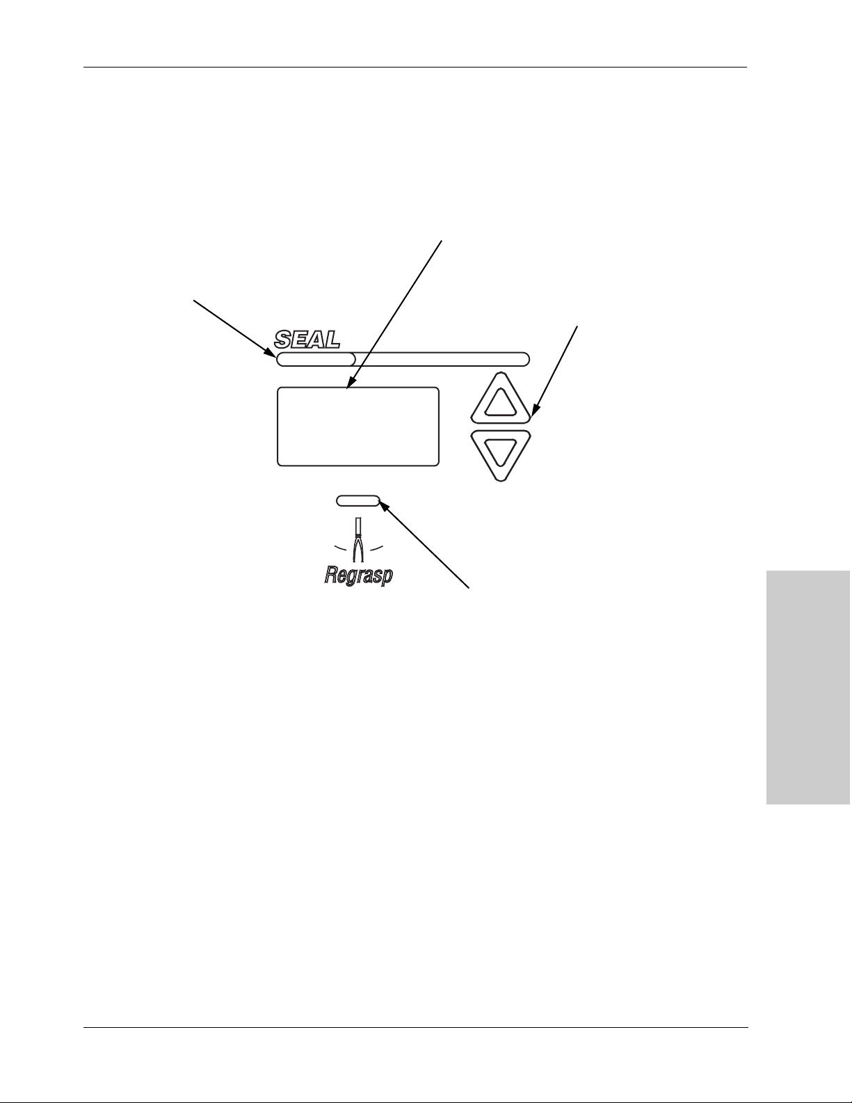
F ig u re 3 -2 .
Vessel sealing intensity control,
activation indicator, and regrasp
indicator
Seal RF Activation Lamp
Illuminates with handswitch or
footswitch activation.
Front Panel
Vessel Sealing Controls and Indicators
Vessel Sealing Intensity Display
A bar graph indicates the relative
seal intensity setting.
Vessel Sealing Intensity Buttons
Press Δ to increase the intensity.
Press ∇ to decrease the intensity.
Regrasp Indicator
Illuminates if the tissue is not sealed.
This may be due to:
• Tissue not responding to RF energy
• Tissue impedance is out of range
• Seal cycle was interrupted before the cycle
was complete
• Maximum seal cycle time has been reached
Controls, Indicators,
and Receptacles
LigaSure Vessel Sealing Generator Service Manual 3-5
Page 26
Front Panel
Vessel Sealing Handset Receptacle (purple)
You can only connect a LigaSure vessel sealing instrument to this receptacle.
F i gu r e 3 -3 .
Vessel sealing handset
receptacle (purple)
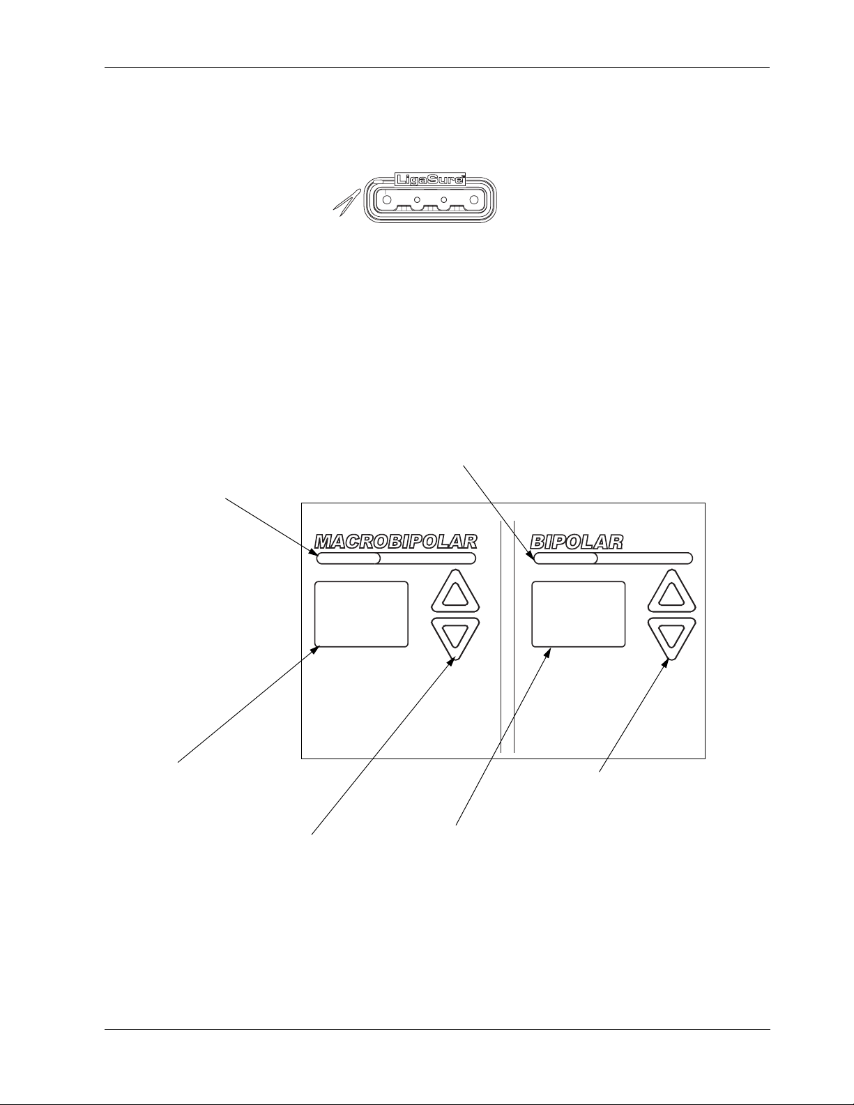
F i gu r e 3 -4 .
Bipolar controls and indicators
Macrobipolar RF Activation Lamp
These lamps illuminate with
handswitch or footswitch. activation.
Connect a footswitching instrument with a
multi-pin connector.
This receptacle is designed to accept a
Valleylab Smart Connector.
When the handset is correctly connected, the vessel sealing receptacle indicator
illuminates green.
Bipolar Controls and Indicators
Bipolar RF Activation Lamp
These lamps illuminate with handswitch
or footswitch activation.
Macrobipolar Power Display
Shows the power setting in Watts
for the Macrobipolar mode.
Macrobipolar Power Buttons
Press Δ to increase the power.
Press ∇ to decrease the power.
Bipolar Power Display
Shows the power setting in
Watts for the Bipolar mode.
Bipolar Power Buttons
Press Δ to increase the power.
Press ∇ to decrease the power.
3-6 LigaSure Vessel Sealing Generator Service Manual
Page 27

Front Panel
Bipolar Handset Receptacle (blue)
You can connect either a footswitching or handswitching bipolar/macrobipolar
instrument to this receptacle.
F ig u re 3 -5 .
Bipolar handset receptacle (blue)
Connect a footswitching instrument with a
two-pin connector.
or
Connect a handswitching instrument with a
three-pin connector.
This receptacle is designed to accept a Valleylab Smart Connector or a Valleylab
Smart Connector adapter. If the bipolar instrument you select does not have a
Smart Connector, you must use the Valleylab Smart Connector adapter (p/n
LS0500).
When the bipolar handset or Valleylab Smart Connector is correctly connected,
the bipolar receptacle indicator light illuminates green.
Controls, Indicators,
and Receptacles
LigaSure Vessel Sealing Generator Service Manual 3-7
Page 28
Rear Panel
Rear Panel
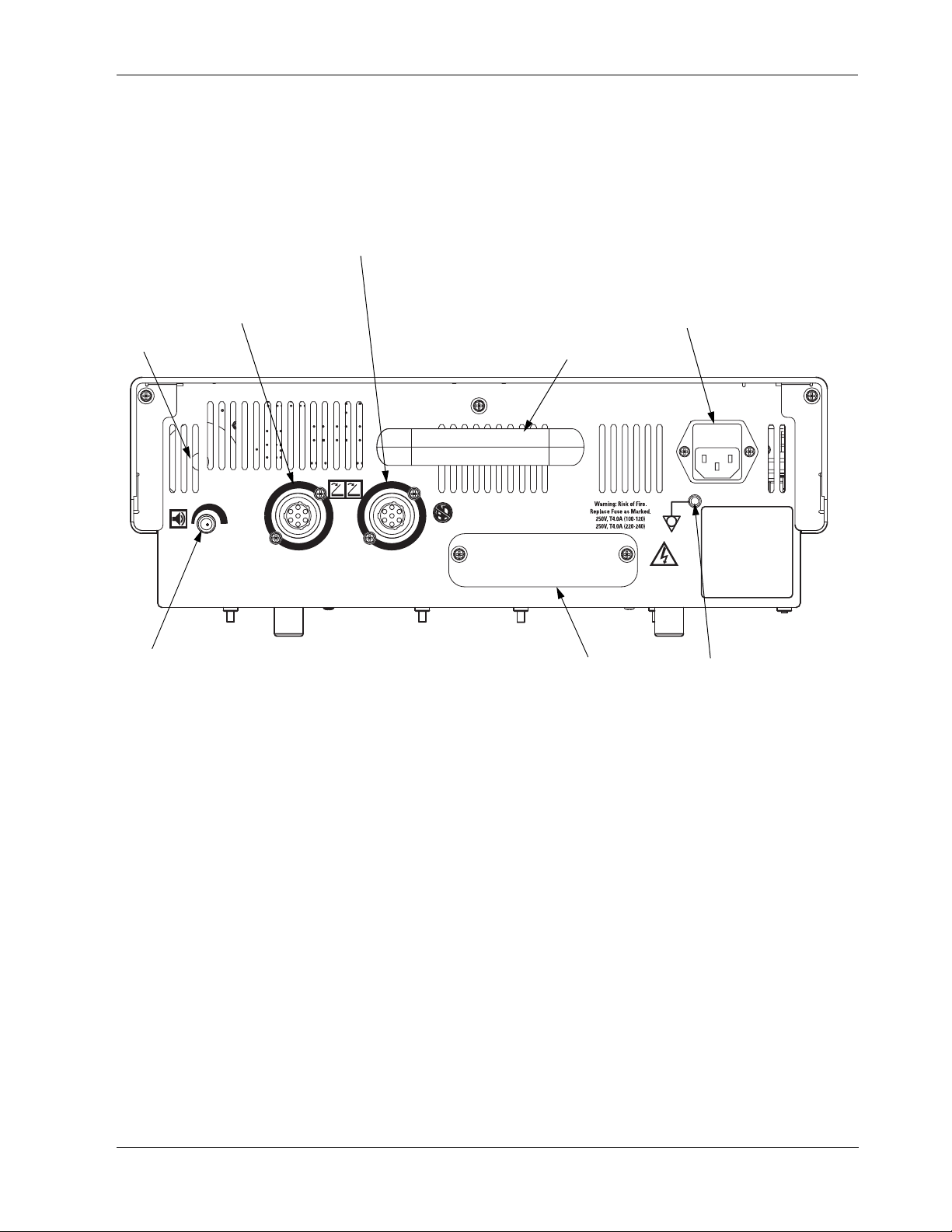
F i gu r e 3 -6 .
Rear panel controls and
receptacles
Bipolar Footswitch
Receptacle (blue band)
Vessel Sealing Footswitch
Receptacle
(purple band)
Power Entry Module
Contains a fuse drawer, with two
fuses, and a receptacle for connecting
the generator power cord.
Speaker
Volume Knob
To increase the volume, turn the knob clockwise.
To decrease the volume, turn it counterclockwise.
You cannot deactivate the activation tone or
adjust the Regrasp indicator tone volume.
Handle
Option Panel
Grounding Lug
Use this to connect the
generator to earth ground.
3-8 LigaSure Vessel Sealing Generator Service Manual
Page 29

Rear Panel
Vessel Sealing Footswitch Receptacle (purple)
Connect either the two-pedal vessel sealing footswitch or the single-pedal vessel
sealing footswitch to this receptacle.
F ig u re 3 -7 .
Vessel sealing footswitch
receptacle (purple)
F ig u re 3 -8 .
Bipolar footswitch receptacle
(blue)
Two Pedal Footswitch
The connected footswitch activates either vessel sealing or
bipolar output for the LigaSure instrument that is connected to
the Vessel Sealing Handset receptacle on the front panel.
Single Pedal Footswitch
The connected footswitch activates only the vessel sealing
output for the LigaSure instrument that is connected to the
Vessel Sealing Handset receptacle on the front panel
Bipolar Footswitch Receptacle (blue)
Connect the bipolar/macrobipolar footswitch when you
connect a bipolar footswitching instrument to the generator.
Connect the two-pedal bipolar footswitch to this receptacle.
The connected footswitch activates bipolar or macrobipolar output for the bipolar
instrument that is connected to the Bipolar handset receptacle on the front panel.
Controls, Indicators,
and Receptacles
LigaSure Vessel Sealing Generator Service Manual 3-9
Page 30
Rear Panel
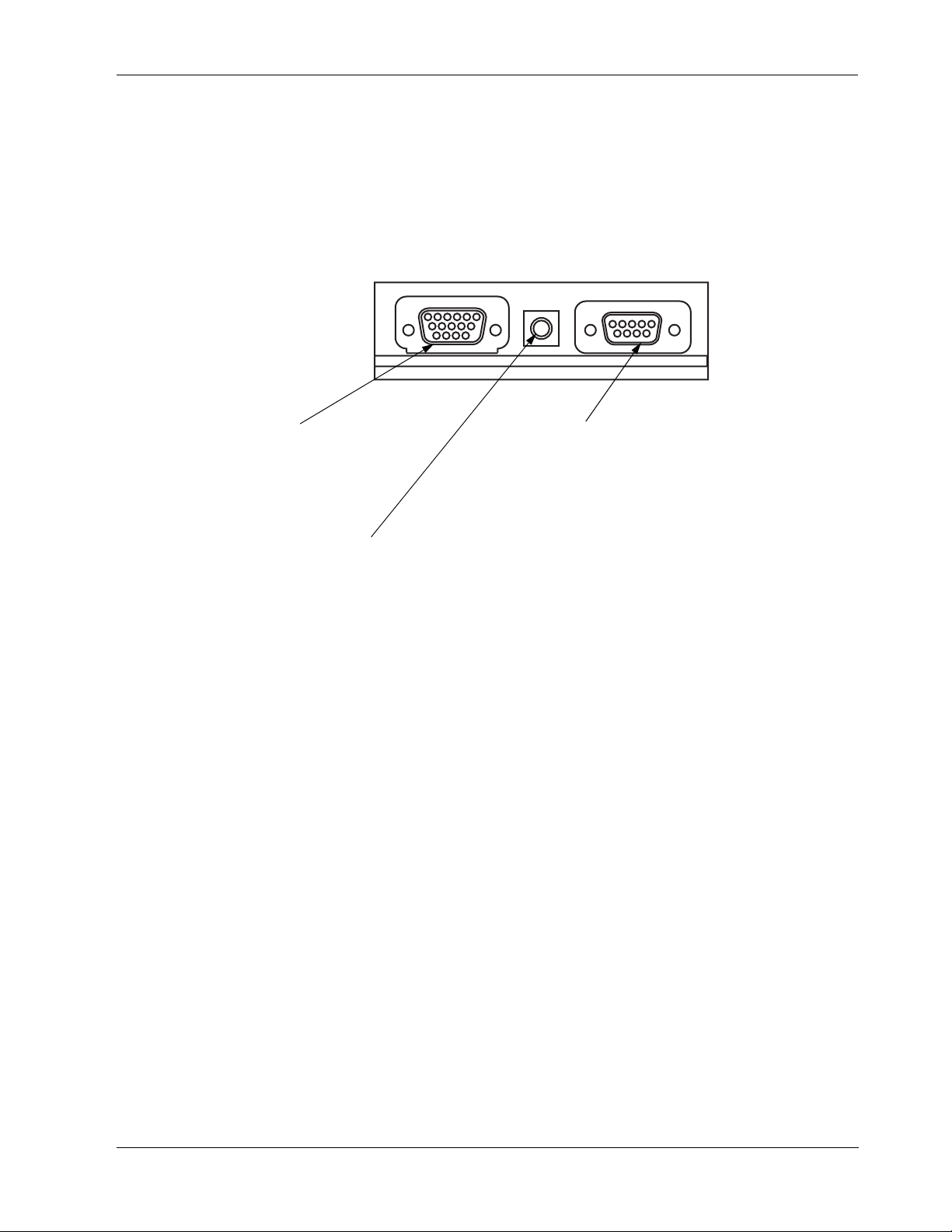
F i gu r e 3 -9 .
The option panel
Option Panel
A removable plate on the rear panel covers a serial port, an RF (radio frequency)
activation port, and an expansion port. To review the technical specifications for
each port, refer to Chapter 4, Technical Specifications.
Expansion Port
Allows a connected device to
receive information about RF
output from the generator.
RF Activation Port
Allows a connected device to receive
information during RF activation of the
generator, which can then generate a response.
in the device.
Serial Port
Allows connecting a computer to the
generator to obtain information using the
RS232 communications protocol.
3-10 LigaSure Vessel Sealing Generator Service Manual
Page 31

4Technical Specifications
All specifications are nominal and subject to change without notice.
A specification referred to as “typical” is within ± 20% of a stated
value at room temperature (25° C / 77° F) and a nominal input
CHAPTER
4
power voltage.
LigaSure Vessel Sealing Generator Service Manual 4-1
Page 32

Performance Characteristics
Performance Characteristics
General
Output configuration Isolated output
Cooling Natural convection
Display Two (2) digital seven-segment displays: 1.9 cm
Mounting A Valleylab cart (UC8009) or a stable flat surface
Dimensions and Weight
(0.75 in.) each
Six (6) bar graph displays: 1.0 cm (0.4 in.) each
Width 38.6 cm (15.2 in.)
Depth 40.6 cm (16.0 in.)
Height 12.7 cm (5.0 in.) not including feet
Weight 5.9 kg (13 lbs)
Operating Parameters
Ambient temperature
range
Relative humidity 15% to 90%, noncondensing
Atmospheric pressure 700 to 1060 millibars
Warm-up time If transported or stored at temperatures outside the
10° to 40° C (50° to 104° F)
operating temperature range, allow one hour for the
generator to reach room temperature before using.
4-2 LigaSure Vessel Sealing Generator Service Manual
Page 33

Transport and Storage
Performance Characteristics
Ambient temperature
range
Relative humidity 0% to 95%, noncondensing
Atmospheric pressure 500 to 1060 millibars
Duration of storage If you stored the generator over one year, check the
– 34° to 70° C (– 29° to 158° F)
battery to measure the Vdc minimum and complete a
full checkout (including calibration) before use.
Contact Valleylab Service for information.
Duty Cycle
Under maximum output settings and rated load conditions (100 ohm load) the
generator is suitable for activation times of 10 seconds on, 30 seconds off, for one
hour.
Internal Memory
Memory type Nonvolatile, battery-backed RAM
Battery type 3 V lithium button cell
Battery life 5 years
Audio Volume
The stated audio levels are at a distance of one meter. Alarm tones meet the
requirements of IEC 60601-2-2.
Technical Specifications
LigaSure Vessel Sealing Generator Service Manual 4-3
Page 34

Performance Characteristics
Activation Tone
Volume (adjustable) 45 dBA minimum
Frequency (nominal) Seal Mode - 440 Hz
Macrobipolar Mode - 520 Hz
Bipolar Mode - 660 Hz
Duration Continuous while the generator is activated.
Seal Complete Tone
Volume (not
adjustable)
Frequency 440 Hz
Duration Two short beeps when vessel sealing cycle is
65 dBA minimum
complete
Regrasp Tone
Volume (not
adjustable)
Frequency 780 Hz
Duration Four pulsed tones
65 dBA minimum
Alarm Tone
Volume (not
adjustable)
65 dBA minimum
Frequency 985 Hz - 780 Hz; 985 Hz nominal
Serial Port
RS-232 compatible; 9600 baud, 8 data bits, 1 stop bit, no parity
A 9-pin connector supporting the following signals:
• pin 2 – isolated transmit (serial data output transmit line)
• pin 3 – isolated receive (serial data input receive line)
• pin 5 – isolated ground (reference for transmit and receive)
4-4 LigaSure Vessel Sealing Generator Service Manual
Page 35

Performance Characteristics
RF Activation Port
The RF activation port is a subminiature phone jack attached to the contacts of a
small relay. The contacts close when you activate the generator, but remain open
at all other times. This port provides a means to tell other equipment that the
generator is producing RF. This may be useful when making EEG or ECG
measurements.
Expansion Port
This 15-pin connector supports the following signals:
• pin 2 – isolated transmit (serial data output transmit line)
• pin 3 – isolated receive (serial data input receive line)
• pin 5 – isolated ground (reference for transmit and receive)
• pin 7 – regrasp indicator (active high)
• pin 8 – RF_ACT indicator (active high when RF is active)
• pin 9 – RF disable: input signal that, when activated by an external device,
disables active RF output
• pin 10 – RF current: output signal proportional to active RF current at 0.8
amp/volt
• pin 11 – RF voltage: output signal proportional to active RF voltage at 205
Vrms/volt
Expansion power (from the low voltage power supply):
+ 5 V (pin 6), – 12 V (pin 14), + 12 V (pin 15), and ground (pins 12 & 13)
Rated fuse current:
1 Amp, Slo Blo, @ +5 Vac
0.25 Amp, Slo Blo, @ ±12 Vac
Technical Specifications
LigaSure Vessel Sealing Generator Service Manual 4-5
Page 36

Performance Characteristics
Low Frequency (50-60 Hz) Leakage Current
(AAMI HF-18-1993)
Enclosure source
current, ground open
Source current, patient leads, all outputs:
Normal polarity, intact
ground
Normal polarity,
ground open
Reverse polarity,
ground open
Sink current at high
line, all inputs
< 300 µA
< 10 µA
< 50 µA
< 50 µA
< 10 µA @ 120 V
< 50 µA @ 264 V
High Frequency (RF) Leakage Current (IEC 60601-2-2)
Bipolar RF leakage
current
≤ 69 mA rms
4-6 LigaSure Vessel Sealing Generator Service Manual
Page 37

Input Power
120 Volt 240 Volt
Performance Characteristics
Maximum power at nominal line
voltage
Idle: 35 VA
Bipolar: 360 VA
Seal: 480 VA
Full regulation range
90 to 135 Vac
Operating range
85 to 140 Vac
Mains current maximum
Idle: 300 mA
Bipolar: 3.0 A
Seal: 4.0 A
Mains line frequency range (nominal)
50 to 60 Hz
Fuses (2) 4 A, 250 V, 3 AG, SLO-BLO Fuses (2) 4 A, 250 V, 3 AG, SLO-BLO
Power plug
3-prong hospital grade connector
rms
rms
rms
Maximum power at nominal line
voltage
Idle: 35 VA
Bipolar: 360 VA
Seal: 480 VA
Full regulation range
186 to 264 Vac
Operating range
170 to 264 Vac
Mains current maximum
Idle: 300 mA
Bipolar: 1.5 A
Seal: 2.0 A
Mains line frequency range (nominal)
50 to 60 Hz
Power plug
3-prong locally approved connector
rms
rms
rms
1
1. The nominal operating power of the LigaSure generator is 480 VA for
a maximum operating current of 2.0 A. However, because the unit is
fused for 4.0 A, the worst-case power would be 880–960 VA (due to input voltages of 220–240 Volts), as indicated by the labeling on the rear
panel of the generator.
Power Cord Specification
This unit was equipped from the factory with either a 110VAC hospital grade
NEMA 5-15 power cord or a 220VAC CEE7/7 power cord. Should the AC power
cord need to be replaced to match another plug configuration, the replacement
plug/cable/receptacle configuration must meet or exceed the following
specifications:
100-120 VAC
Cable - SJT16/3, IEC color code, maximum length 15 ft (5 m)
Plug - minimum 10 A - 125 VAC
Unit receptacle - IEC female, minimum 10 A - 125 VAC
Technical Specifications
LigaSure Vessel Sealing Generator Service Manual 4-7
Page 38

Standards and IEC Classifications
220-240 VAC
Cable - H05VVF3G1.0 VDE, maximum length 15’ (5 meters)
Plug - minimum 6 A - 250VAC
Unit receptacle - IEC female, minimum 6 A - 250VAC
Standards and IEC Classifications
The LigaSure Generator meets all pertinent clauses of IEC 60601-1 second
edition and IEC 60601-2-2 third edition.
F
ATTENTION
Consult accompanying documents.
The generator output is floating (isolated) with respect to
ground.
DANGER
Explosion risk if used with flammable anesthetics.
To reduce the risk of electric shock, do not remove the cover.
Refer servicing to qualified service personnel.
Non-Ionizing Radiation
Classified with respect to electrical shock, fire, and
mechanical hazards only in accordance with UL60601-1 and
CAN/CSA C22.2 No. 601.1.
Class I Equipment (IEC 60601-1)
Accessible conductive parts cannot become live in the event of a basic insulation
failure because of the way in which they connect to the protective earth
conductor.
4-8 LigaSure Vessel Sealing Generator Service Manual
Page 39

Standards and IEC Classifications
Type CF Equipment (IEC 60601-1)/Defibrillator Proof
This generator provides a high degree of protection against electric
shock, particularly regarding allowable leakage currents. It is type CF
isolated (floating) output and poses no fibrillation danger.
This generator complies with the ANSI/AAMI HF18 specifications
for “defibrillator proof” designation and IEC 60601-2-2.
Liquid Spillage (IEC 60601-2-2, clause 44.3)
This generator enclosure is constructed so that liquid spillage in normal use does
not wet electrical insulation or other components which, when wet, are likely to
affect adversely the safety of the generator.
Static Electricity Discharge Interference (IEC 60601-1-2
and IEC 61000-4-2)
This generator enclosure can withstand an 8 kV electrostatic air discharge.
Electromagnetic Interference
When placed on or beneath an activated Valleylab electrosurgical generator, this
generator operates without interference. The generator minimizes electromagnetic
interference to video equipment used in the operating room.
Electromagnetic Compatibility (IEC 60601-1-2 and
IEC 60601-2-2)
This generator complies with the appropriate IEC 60601-1-2 and 60601-2-2
specifications regarding electromagnetic compatibility.
Notice
The LigaSure should not be used adjacent to or stacked with equipment other
than specified in the LigaSure User Guide and Service Manual. If adjacent or
stacked use is necessary, the LigaSure should be observed to verify normal
operation in the configuration in which it will be used.
The LigaSure intentionally applies RF energy for diagnosis or treatment during
activation. Observe other electronic medical equipment in the vicinity during the
LigaSure activation for any possible adverse electromagnetic effects. Ensure
adequate separation of electronic medical equipment based on observed
reactions.
The use of accessories, other than specified in the LigaSure User Guide and
Service Manual, may result in increased emissions or decreased immunity of the
LigaSure.
Technical Specifications
LigaSure Vessel Sealing Generator Service Manual 4-9
Page 40

Standards and IEC Classifications
Voltage Transients (Emergency Generator Mains
Transfer)
This generator operates in a safe manner when you transfer between line AC and
an emergency generator voltage source.
Guidance and manufacturer's declaration - electromagnetic emissions
The LigaSure is intended for use in the electromagnetic environment specified below. The customer or the user of the
LigaSure should ensure that it is used in such an environment.
Emissions test Compliance Electromagnetic environment -
guidance
RF emissions
CISPR 11
RF emissions
CISPR 11
Harmonic emissions
IEC 61000-3-2
Voltage fluctuations/ flicker
emissions IEC61000-3-3
Group 1 The LigaSure uses RF energy only for
its internal function. Therefore, its RF
emissions are very low and are not
likely to cause any interference in
nearby electronic equipment.
Class A The LigaSure is suitable for use in all
establishments other than domestic
and those directly connected to the
Class A
Complies
public low-voltage power supply
network that supplies buildings used
for domestic purposes.
4-10 LigaSure Vessel Sealing Generator Service Manual
Page 41

Standards and IEC Classifications
Guidance and manufacturer's declaration - electromagnetic immunity
The LigaSure is intended for use in the electromagnetic environment specified below. The customer or the user of the
LigaSure should assure that it is used in such an environment.
Immunity test IEC 60601 test
Electrostatic discharge
(ESD)
IEC 61000-4-2
Electrical fast transient/
burst IEC 61000-4-4
Surge
IEC 61000-4-5
Voltage dips, short
interruptions and voltage
variations on power supply
input lines
IEC 61000-4-11
+/-6 kV contact
+/-2 kV for power
supply lines
+/-1 kV for input/
output lines
+/-1 kV differential
+/-2 kV common
(>95% dip in Ut)
for 0,5 cycle
(>60% dip in Ut)
(>30% dip in Ut)
for 25 cycles
(>95% dip in Ut)
level
+/-8 kV air
mode
mode
<5% Ut
40% Ut
for 5 cycles
70% Ut
<5% Ut
for 5 sec
Compliance level Electromagnetic environment -
guidance
+/-6 kV contact
+/-8 kV air
+/-2 kV for power
supply lines
+/-1 kV for input/
output lines
+/-1 kV differential
mode
+/-2 kV common
mode
<5% Ut
(>95% dip in Ut)
for 0,5 cycle
40% Ut
(>60% dip in Ut)
for 5 cycles
70% Ut
(>30% dip in Ut)
for 25 cycles
<5% Ut
(>95% dip in Ut)
for 5 sec
Floors should be wood, concrete or
ceramic tile. If floors are covered with
synthetic material, the relative humidity
should be at least 30%.
Mains power quality should be that of a
typical commercial or hospital environment.
Mains power quality should be that of a
typical commercial or hospital environment.
Mains power quality should be that of a
typical commercial or hospital environment.
If the user of the LigaSure requires
continued operation during power mains
interruptions, it is recommended that the
LigaSure be powered from an
uninterruptible power supply or a battery.
Power frequency (50/60
Hz) magnetic field
IEC 61000-4-8
NOTE: Ut is the a.c. mains voltage prior to the application of the test level.
3 A/m 3 A/m Power frequency magnetic fields should be
at levels characteristic of a typical location
in a typical commercial or hospital
environment.
LigaSure Vessel Sealing Generator Service Manual 4-11
Technical Specifications
Page 42

Standards and IEC Classifications
Guidance and manufacturer's declaration - electromagnetic immunity
The LigaSure is intended for use in the electromagnetic environment specified below. The customer or the user of the
LigaSure should assure that it is used in such an environment.
Immunity test IEC 60601 test level Compliance level Electromagnetic environment -
guidance
Portable and mobile RF communications
equipment should be used no closer to any
part of the LigaSure, including cables, than
the recommended separation distance
calculated from the equation applicable to
the frequency of the transmitter.
Recommended separation distance
0.5√P
Conducted RF IEC
61000-4-6
Radiated RF
IEC 61000-4-3
3 Vrms
150KHz to 80MHz
3 V/m
80MHz to 2.5GHz
7 V
7 V/m
d =
d =
0.5√P 80MHz to 800MHz
√P 800MHz to 2.5GHz
d =
Where P is the maximum output power
rating of the transmitter in watts (W)
according to the transmitter
manufacturer and d is the
recommended separation distance in
meters (m).
Field strengths from fixed RF
transmitters, as determined by an
electromagnetic site survey, should be
less than the compliance level in each
frequency range
Interference may occur in the vicinity of
equipment marked with the following
symbol:
NOTE 1: At a 80MHz and 800MHz, the higher frequency range applies.
NOTE 2: These guidelines may not apply in all situations. Electromagnetic propagation is affected by absorption and
reflection from structures, objects and people.
a. Field strengths from fixed transmitters, such as base stations for radio (cellular/cordless) telephones and land
mobile radios, amateur radio, AM and FM radio broadcast and TV broadcast cannot be predicted theoretically with
accuracy. To assess the electromagnetic environment due to fixed RF transmitters, an electromagnetic site survey
should be considered. If the measured field strength in the location in which the LigaSure is used exceeds the
applicable RF compliance level above, the LigaSure should be observed to verify normal operation. If abnormal
performance is observed, additional measures may be necessary, such as reorienting or relocating the LigaSure.
b. Over the frequency range 150kHz to 80MHz, field strengths should be less than 7V/m.
4-12 LigaSure Vessel Sealing Generator Service Manual
Page 43

Standards and IEC Classifications
Recommended separation distances between portable and mobile RF communication equipment and the
LigaSure
The LigaSure is intended for use in an electromagnetic environment in which radiated RF disturbances are controlled.
The Customer or the user of the LigaSure can help prevent electromagnetic interferences by maintaining a minimum
distance between portable and mobile RF communications equipment (transmitters) and the LigaSure as
recommended below, according to the maximum output power of the communications equipment.
Separation distance according to frequency of transmitter (m)
Rated maximum output
power of transmitter (W)
0.01 0.05 m 0.05 m 0.1 m
0.1 0.16 m 0.16 m 0.32 m
1 0.5 m 0.5 m 1 m
10 1.6 m 1.6 m 3.2 m
150 kHz to 80MHz
0.5√P
d =
80MHz to 800MHz
d = 0.5√P
800MHz to 2.5GHz
d = √P
100 5 m 5 m 10 m
For transmitters rated at a maximum output power not listed above, the recommended separation distance d in
meters (m) can be estimated using the equation applicable to the frequency of the transmitter, where P is the
maximum output power rating of the transmitter in watts (W) according to the transmitter manufacturer.
NOTE 1: At 80MHz and 800MHz, the separation distance for the higher frequency range applies.
NOTE 2: These guidelines may not apply in all situations. Electromagnetic propagation is affected by absorption and
reflection from structures, objects and people.
Technical Specifications
LigaSure Vessel Sealing Generator Service Manual 4-13
Page 44

Output Characteristics
Output Characteristics
Maximum Generator Output
Maximum Open
Circuit Voltage
Mode
Macrobipolar 760 (380) 2.2 95 1.5
Bipolar 335 (168) 2.2 95 1.5
Seal 575 (288) 4.4 150 1.5
Vpp(Vp)
Maximum Short
Circuit Current*
A
rms
Maximum Power
Setting
watts
Crest
Factor**
* Open circuit values obtained with a Pearson 411 current measurement with a 1K
ohm load attached to the handset.
** Crest factor is an indication of a waveform’s ability to coagulate without a
cutting effect.
4-14 LigaSure Vessel Sealing Generator Service Manual
Page 45

F ig u re 4 -1 .
Output voltage at specific intensity
settings in the vessel sealing
mode
Output Characteristics
Output Waveform
Macrobipolar/Bipolar 473 kHz sinusoid. 100% duty cycle.
Seal 473 kHz sinusoid, pulsed.
Table 4-1
Open Circuit Output Volts Peak
(rms)
Mode Generator Intensity Setting — Bars
12345
Seal 51 (36) 82 (58) 115 (81) 139 (98) 151 (107)
LigaSure Vessel Sealing Generator Service Manual 4-15
Technical Specifications
Page 46

Output Characteristics
F i gu r e 4 -2 .
Output voltage at specific
intensity settings in the
macrobipolar and bipolar modes
Table 4-2.
Open Circuit Output Volts Peak
(rms)
Mode Generator Power Setting — Watts
10 25 50 75 90 95
Macro Bipolar 133 (94) 201 (142) 293 (207) 355 (251) 354 (250) 287 (203)
Bipolar 51 (36) 82 (58) 115 (81) 139 (98) 151 (107) 266 (110)
4-16 LigaSure Vessel Sealing Generator Service Manual
Page 47

Output Power vs. Impedance Graphs
The following graphs depict the RF output as applied to tissue impedance for
generator operative modes of macrobipolar and bipolar outputs.
F ig u re 4 -3 .
Power (in watts) versus
impedance (in ohms) in the vessel
sealing mode
Output Power vs. Impedance Graphs
LigaSure Vessel Sealing Generator Service Manual 4-17
Technical Specifications
Page 48

Output Power vs. Impedance Graphs
F ig u re 4 -4 .
Power (in watts) versus
impedance (in ohms) in the
macrobipolar mode
F ig u re 4 -5 .
Power (in watts) versus
impedance (in ohms) in the bipolar
mode
4-18 LigaSure Vessel Sealing Generator Service Manual
Page 49

5Principles of Operation
This chapter provides detailed information about how the LigaSure
vessel sealing generator functions and how the internal
components interact.
CHAPTER
5
The circuitry resides on eight printed circuit boards: the control
board, the display board, the footswitch board, the low voltage
power supply board, the high voltage power supply board, the
Radio Frequency (RF) board, and two smart connector boards.
This chapter includes the following information:
• A block diagram that illustrates how the generator components
interconnect
• A general description of how the generator works
• A detailed description of the circuitry for each printed circuit board
LigaSure Vessel Sealing Generator Service Manual 5-1
Page 50

Block Diagram
Block Diagram
F i gu r e 5 -1 .
A diagram of generator
component interconnections
5-2 LigaSure Vessel Sealing Generator Service Manual
Page 51

Functional Overview
Functional Overview
The LigaSure vessel sealing system is an isolated output electrosurgical generator
that provides power for vessel sealing and bipolar surgery.
• It includes the following features:
• LigaSure vessel sealing technology
• Vessel sealing regrasp indicator alerts you if the instrument jaws have shorted
out, if the system has reached the maximum seal cycle time, or if the tissue
impedance is out of range
• Bipolar and macrobipolar modes
• Instant Response technology
• Memory button to recall the most recently used intensity and power settings
• Smart interface for connecting a Valleylab LigaSure handset or smart
connector adapter
• Adjustable volume for the activation tone
• Handswitch or footswitch activation
• RF activation port, RS-232 serial port, and expansion port
Vessel Sealing
The LigaSure vessel sealing system provides precise energy delivery and
electrode pressure to vessels for a controlled time period to achieve a complete
and permanent fusion of the vessel lumen. This system works on isolated arteries
and veins up to and including 7 mm in diameter and tissue bundles. The system
has been optimized to produce minimal sticking, charring, or thermal spread to
adjacent tissue.
Bipolar Operation
Two modes are available:
• Bipolar – for most applications. The LigaSure bipolar system provides tissue
dessication with low voltage to prevent sparking. The power remains constant
over a specific range of tissue impedance, allowing a consistent tissue effect.
Principles of Operation
• Macrobipolar – for bipolar cutting or rapid coagulation. The system provides
higher voltage and greater power than with the bipolar mode.
Instant Response Technology
The LigaSure generator automatically senses tissue impedance and adjusts the
output voltage to maintain a consistent effect across different tissue types. This
adjustment is based on the power setting and the level of tissue impedance. The
system controls maximum output voltage to reduce tissue damage and to
minimize sparking.
LigaSure Vessel Sealing Generator Service Manual 5-3
Page 52

Control Board
Control Board
Refer to Chapter 10, Service Parts, for components and the Schematics
Supplement for system schematics.
The control board contains the circuitry that controls the generator, including the
indicators and switches on the display board and the Radio Frequency (RF) output
stage on the RF board. Firmware on the control board performs many diagnostic
and initialization routines, and reports errors as alarm numbers on the front panel.
The control board interfaces with the RF board through a 96-pin card edge
connector. It interfaces with the display board through a 64-pin ribbon cable.
Microcontrollers
Two microcontrollers on the control board control the LigaSure system. These
microcontrollers communicate with each other through a shared random access
memory (RAM). The main microcontroller (U5) performs all system functions
except the feedback control of the generator RF output. The feedback
microcontroller (U11), which is a separate, dedicated microcontroller, controls the
real-time-critical feedback control of the generator RF output. All system analog
signals are available to these microcontrollers.
A third microcontroller (U9) functions as an application-specific integrated
circuit, or ASIC. It generates the RF drive waveforms (T_ON\) for the RF output
stage.
Main Microcontroller
The main microcontroller (U5) is an 80C562 that incorporates an 8-input
multiplexed 8-bit A/D converter. The main microcontroller is responsible for
overall system control. It monitors all dosage error functions and safety circuits. It
implements the user interface, including activation control. It is primarily
responsible for these functions:
• Segment display drivers and LED update
• Power control buttons, mode buttons, and the activation interface
• Serial port interface
• Alarm handling
• Audio control
• Memory control and storage (system alarms with time stamps; calibration
values)
• Real-time clock control and interface
• Internal self-tests
• Communicating with the feedback microcontroller
5-4 LigaSure Vessel Sealing Generator Service Manual
Page 53

Control Board
Main Microcontroller Memory
An ST Microelectronics PSD835G2 programmable systems device (U3) provides
program memory (512K x 8 external Flash Memory) and data memory (2K x 8
external battery-backed static RAM) for the main microcontroller. Additional data
memory is available from these sources:
• 256 x 8 microcontroller internal RAM
• 4K x 8 external static RAM (U4) shared with the feedback microcontroller
Battery-Backed RAM
A socket on the control board contains a 3.0 V lithium button cell battery (BT1).
This battery provides backup power for the 2K x 8 external RAM on the
PSD835G2 device (U3) used by the main microcontroller. The battery-backed
RAM stores calibration constants, last setup parameters, and temporary data.
Feedback Microcontroller
The feedback microcontroller (U11), like the main microcontroller, is an 80C562.
It receives commands from the main microcontroller and, when the generator is
activated, establishes the appropriate relay closures and activates RF output. It
continually adjusts the output signal of the generator by controlling the high
voltage DC power supply and the RF clock circuitry. It is primarily responsible
for these functions:
Principles of Operation
• T_ON waveform control
• Constant voltage, current, and power feedback control
• ECON initialization
• Real-time information update (actual voltage, current, power, impedance,
effect mode)
• Memory tests
• Communicating with the main microcontroller
Feedback Microcontroller Memory
An ST Microelectronics PSD835G2 programmable systems device (U3) provides
program memory (512K x 8 external Flash Memory) and data memory (2K x 8
external static RAM) for the feedback microcontroller. Additional data memory is
available from these sources:
• 256K x 8 microcontroller internal RAM
• 4K x 8 external static RAM (U4) shared with the main microcontroller
LigaSure Vessel Sealing Generator Service Manual 5-5
Page 54

Control Board
Shared RAM
An IDT 713425A device (U4) with semaphore flags provides the 4K x 8 external
shared static RAM. The shared RAM allows the main microcontroller (U5) and
the feedback microcontroller (U11) to share common variables. It functions as a
communications interface between the main and feedback microcontrollers. It
also provides additional general-purpose RAM to these microcontrollers.
I/0 Expansion
Three devices provide input/output (I/O) expansion capabilities:
• One ST Microelectronics PSD835G2 programmable systems device (U6)
• One ST Microelectronics PSD835G2 programmable systems device (U3)
• One 82C55 expansion port (U2)
The ST Microelectronics PSD835G2 incorporates 52 individually programmable
I/O pins divided into 6 ports of 8-bits each and 1 port of 4-bits. Of the general I/O
pins, 24 can alternatively be utilized for 24 PLD outputs. The PSD835G2 also
contains 512K x 8 Main Flash Memory, 32K x 8 Boot Flash Memory, 2K x 8 of
SRAM, and a power management unit for battery backup. The power
management unit for battery backup is not used by the Feedback microcontroller.
The I/O expansion capabilities of the Feedback PSD835G2 has a built-in IEEE
1149.1 compliant JTAG serial port to allow full-chip in-System Programmability
(ISP). The Main PSD835G2 is #1 on the JTAG chain and the Feedback
PSD835G2 with the exception that the 512K x 8 Flash Memory for the Main
PSD835G2 is accessed in a bank switching methodology and the I/O expansion
capabilities are configured as outputs for lamp control, keyboard scanning, and
chip selects.
The 82C55 is a generic I/O expander which incorporates 24 I/O pins divided into
3 ports of 8-bits each. The 82C55 is configured as all inputs, and is used to read
the keyboard, keying signals, accessory switches, and system status flags.
Keyboard Interface and Activation Inputs
The keyboard interface is a simple row and column matrix between three bank
select output lines (BANK0–BANK2) on port A of the PSD835G2 (U3). The
main microcontroller and eight keyboard (KBD_D0–KBD_D7) input lines on
port A of the expansion port 82C55 (U2) use this interface.
Port B of the expansion port 82C55 reads activation inputs from the IsoBloc
decoding circuits on the RF board.
Power Supply Supervisor Circuit
The power supply supervisor circuit (U14), a MAX691, generates a Reset signal
and a Reset\ signal for the main microcontroller (U5) if the power supply voltage
to the control board drops below 4.65 V. It also generates a voltage sensitive chip
select for the PSD835G2 (U6) and the PSD835G2 (U3). The low voltage
threshold (4.65 V) places U3 and U6 in sleep mode and disables the 2K x 8
external static RAM.
5-6 LigaSure Vessel Sealing Generator Service Manual
Page 55

Control Board
A/D and D/A Conversion
Each 80C562 microcontroller (U5 and U11) contains an 8-channel multiplexed 8bit analog-to-digital (A/D) converter. Incorporating fixed gain control in the sense
circuits on the RF board and prescaling based on the expected input voltage or
current values enhance the resolution of voltage and current sense inputs.
An MP7226 quad digital-to analog (D/A) converter (U15) provides 4-channel 8bit D/A capabilities for the feedback microcontroller to output 0 to 5 Vdc analog
voltages.
Waveform Generation (T_ON)
A dedicated 89C54 microcontroller (U9) generates the RF drive waveforms
(T_ON\) for the RF output amplifier on the RF board. The microcontroller
functions as an application-specific integrated circuit (ASIC), performing an
endless series of repetitive tasks while enabled.
The feedback microcontroller (U11) holds the T_ON microcontroller (U9) in a
reset state until the feedback microcontroller detects a valid activation request.
After validating the request, the feedback microcontroller releases the T_ON
microcontroller from reset and communicates a 4-bit code - 0 - that represents the
generator mode to be activated.
Principles of Operation
The code generates a unique waveform pattern to be delivered to the RF output
stage of the generator. The T_ON microcontroller reads and evaluates the code
and, if the code value is acceptable, repetitively generates the appropriate
waveform until the activation request ends. After the request ends, the feedback
microcontroller places the T_ON microcontroller back into reset.
If the code received by the T_ON microcontroller is not valid, the internal
program sets an error flag, deactivates all output signals, and remains in an error
state until the user resets the system.
T_ON Average Check
A capacitor filters the T_ON waveform generator output, returning it to the main
microcontroller as a DC voltage value called T_ON average. Each distinct output
mode of the T_ON waveform generator produces a different T_ON average. The
main microcontroller continually checks the T_ON average for compliance with
the calibrated value to ensure that the T_ON waveform generator is operating
properly.
The T_ON average signal rests at 5 V when the generator is not activated and
drops to the calibrated value when activation occurs. The main microcontroller
checks to make sure the T_ON average signal is within ± 15 counts of the
calibrated value.
LigaSure Vessel Sealing Generator Service Manual 5-7
Page 56

Control Board
Audio Alarm
The audio alarm circuit resides on the footswitch board. Both software and
hardware control the audio alarm.
• The feedback microcontroller, in response to activation inputs, alarms, and
power-up, writes to a digital-to-analog converter (DAC) chip, U15, which
generates an analog control signal, V_FREQ. This signal provides software
control for the audio alarm. The V_FREQ signal connects from the control
board to the RF board through the 96-pin connector, and then from the RF
board to the footswitch board through the 20-pin footswitch ribbon connector.
• The RF_TONE\ signal provides hardware control. RF sensing circuitry on the
RF board generates the RF_TONE\ signal in the RF output stage.
Serial Interface
The RS-232 serial port is a software-polled interface to the main microcontroller
(U5). You can use it for diagnostics and calibration. Transmission and receipt of
command strings do not stop real time processing, except as single characters are
read from or written to the serial port. The serial port configuration follows:
• 9600 baud
• 8 data bits
• 1 stop bit
• no parity
This timing is derived from the main microcontroller oscillator frequency of
11.0592 MHz.
The control board serial port signals connect to the RF board through the 96-pin
connector. The signals then connect to the 9-pin serial port connector on the RF
board.
Dosage Error Algorithm
The basis of the dosage error algorithm for the closed loop modes (bipolar and
seal) is a comparison between two microcontroller/sensor sets:
• Main microcontroller, current and voltage sensors
• Feedback microcontroller, current and voltage sensors
While the feedback microcontroller operates the generator, the master
microcontroller continuously monitors generator operation, calculating and
checking several values:
• Voltage and current input to the microcontrollers
• High voltage control signal
• High voltage sense signal
• Desired value (entered at the front panel) at the main microcontroller
• Desired value (entered at the front panel) at the feedback microcontroller
5-8 LigaSure Vessel Sealing Generator Service Manual
Page 57

Control Board
The master microcontroller, using the dosage error algorithm, checks to make sure
the feedback microcontroller is operating the generator within specific
parameters:
• During idle, the main sensors receive less than 50% of full scale.
• The high voltage (HV) power supply board control signal is greater than 90%
and the V/I signals are less than 10% of full scale.
• The HV power supply and the HV sense signals are within one volt of each
other.
• The power readings at the main and feedback microcontrollers do not differ
by 50 watts or more.
• Sensors connected to the main microcontroller are not stuck at 100% of full
scale.
• Desired power at the main and feedback microcontrollers are the same.
• Actual power is below the error threshold as defined by IEC 60601-2-2,
Dosage Error Limits.
If the algorithm detects that the generator exceeds one or more these parameters,
it signals an error condition. The system displays an error message and shuts
down all generator output.
Instant Response Algorithm
This algorithm controls the current, power, and voltage adjustments for all modes.
Controlling the maximum output voltage reduces high frequency leakage, reduces
video interference, and minimizes sparking. At low impedances, keeping the
current constant protects output circuitry. At high impedances, keeping the
voltage constant limits arcing and electro-magnetic interference.
Constant Current
The algorithm holds output current constant according to this equation:
I = (P/R) ˆ(1/2)
where I is the output current, P is the power set by the user, and R is the constant
current to constant power impedance switchpoint.
Principles of Operation
Constant Power
The algorithm maintains the power set by the user.
Constant voltage
The algorithm controls the output voltage according to the following equation:
V = (P*R) ˆ(1/2)
where V is the output voltage, P is the power set by the user, and R is the constant
power to constant voltage impedance switchpoint. In some high impedance
conditions, the algorithm modifies this equation to reduce voltage more rapidly.
LigaSure Vessel Sealing Generator Service Manual 5-9
Page 58

Front Panel
Front Panel
The front panel consists of an injection molded plastic bezel with a membrane
keyboard, power switch, and seal and bipolar smart receptacles. These front panel
components connect to the display board and the RF board.
Membrane Keyboard
A high strength adhesive attaches the membrane keyboard to the bezel. The
keyboard is not removable. The membrane contains 16 metal dome push-button
switches. Six of these switches control the up and down sequencing of the power
seven-segment and bar lamp light-emitting diodes (LEDs). One switch controls
the Memory function, which stores previous settings.
The membrane also contains three illumination window LEDs, one for each RF
activation mode. A 12-pin flat ribbon cable connects the membrane keyboard
switches and LEDs to the display board.
Power Switch
A double pole single throw switch snaps into the front of the bezel. This switch
connects the AC mains to supply power to the generator.
Display Board
Refer to Chapter 10, Service Parts, for components and the Schematics
Supplement for system schematics.
The display board resides in the front panel assembly. It contains RF indicator
lamps, seven-segment LED power setting displays, seal bar lamp setting displays,
and a regrasp indicator lamp. The display board switch circuitry includes the LED
and lamp driver circuitry, power selection switches, mode selection switches, and
the smart switch LED driver circuit.
RF Indicator Lamps
The RF indicator lamps illuminate during RF activation to indicate the presence
of RF power. Two incandescent bulbs illuminate each of the three indicator bars
(seal, bipolar, and macrobipolar) on the front panel.
• LP11 and LP12 illuminate the blue bipolar bar, indicating bipolar activation.
• LP7 and LP8 illuminate the light blue macrobipolar bar, indicating cut
activation.
• LP3 and LP4 illuminate the blue seal bar, indicating seal activation.
The BIP_LMP, MACRO_LMP, and VS_LMP signals control the RF indicator
lamps. These signals originate from port A of the main microcontroller
programmable peripheral (U3) on the control board.
5-10 LigaSure Vessel Sealing Generator Service Manual
Page 59

Display Board
Q1 through Q4 MOSFETS turn the RF indicator lamps on and off. Resistors R4,
R5, R9, R10, R13, and R14 set the amount of current flowing through the lamps
when they are turned on. The value of these resistors varies for each indicator bar,
depending on the color of the bar, to make the different colors of the bars
illuminate with equal intensities.
LED and Seven-Segment Display Drivers
This circuit contains two display drivers: the LEDs and the seven-segment
displays. The bar lamp LEDs indicate the seal intensity. The seven-segment
displays indicate the bipolar and macrobipolar power settings.
Each display driver (U10 and U11) can drive up to eight banks of eight LEDs by
multiplexing the time at which it turns on each bank and controlling how long the
bank remains on. Wiring the banks together increases the time that a group of
LEDs can remain on, effectively increasing the brightness of that group.
U10 drives the discrete bicolor LEDs. These include the red and green indicators
for the smart connectors in the bipolar and seal modes. The anode of each mode
selection LED connects to driver U10. Using pairs of the driver digit lines makes
the effective duty ratio for these LEDs 1/4.
U11 drives the seven-segment displays that indicate power settings. U5 and U6
indicate the bipolar power setting; U2 and U3 indicate the macrobipolar power
setting; and U1, U4, U7, U8, and U9 indicate the seal intensity bar lamp setting.
Seal bar lamp U12 illuminates yellow when you turn the power on and the system
completes its self-diagnostic test successfully. The yellow lamp setting
corresponds to a default seal power setting of zero output. The anodes of these
displays each connect to only one digit line of the driver. The effective duty cycle
is 1/8 for each seven-segment display.
Principles of Operation
Some filtering components are associated with U10 and U11. Bypass capacitors
C3, C4, C5, C6, C8, and C9 connect between + 5V and DGND. C3, C5, C6, and
C8 have a relatively small capacitance value (0.1 µF or less) to filter higher
frequency noise. C4 and C9 have a relatively large capacitance value of 47 µF to
supply the large spikes of current for the LEDs generated by the multiplexing
action of the drivers, which typically occurs at 250 Hz.
Resistor components R16 through R22 and R31 reduce the input impedance of the
display driver inputs as seen by the main microcontroller on the control board.
This rounds off the edges of these digital signals, reducing high frequency
emissions. The lower impedance also reduces the susceptibility of the circuit to
noise from other circuits.
LigaSure Vessel Sealing Generator Service Manual 5-11
Page 60

Display Board
Regrasp Display
Q4 drives the discrete LP1 regrasp lamp on and off with seal mode operation only.
When Q4 is on, resistor R8 controls lamp LP1 current to control lamp brightness.
When received from the control board, a positive TTL level signal activates this
display.
Mode Select and Power Control Switches
The mode select and power control switches operate in an 8-bit control format:
Bits No. of Wires Purpose
6 2, in pairs 1 pair for each of three operative
modes: seal, bipolar, and macrobipolar
1 1 memory recall function
1 1 BANK_0, enables the keyboard
membrane
The main microcontroller selects the BANK_0 enable switch through this path:
Port A (on the control board programmable peripheral, U3)
through
Connector J1
to
BANK_0 enable switch
When turned on, MOSFET Q5 activates the keyboard switches.
Command control signals KBD-01 through KBD-06, originating in the control
board, choose the up and down power select bit lines:
Command Signals Function
KBD-01 and 02 Up/Down seal intensity select
KBD-03 and 04 Up/Down macrobipolar power select
KBD-05 and 06 Up/Down bipolar power select
KBD-00 Memory recall select
To read the switches, the main microcontroller enables BANK_0 and reads the
state of the keyboard switch return lines, KBD-00 through KBD-06 through the
following path:
BANK_0 enable switch
through
Connector J1
to
Port A (on the control board I/O expansion port, U2)
5-12 LigaSure Vessel Sealing Generator Service Manual
Page 61

Footswitch Board
Footswitch Board
Refer to Chapter 10, Service Parts, for components and the Schematics
Supplement for system schematics.
The footswitch board resides inside the rear panel. It contains decode circuitry for
accepting and decoding footswitch inputs and an audio circuit for announcing
generator activation and various alarm tones. The footswitch board interfaces with
the RF board.
Footswitch Decode Circuit
Two bipolar footswitch connectors, mounted on the footswitch board, extend
through the rear panel. These footswitch connectors (J2 and J4) accept bipolar and
seal footswitch plugs and provide footswitching capability to activate and deliver
RF energy to the instrument receptacles on the front panel. The bipolar footswitch
connector (J2), color coded blue, mates with the chassis rear panel receptacle
highlighted by a blue annular ring. This dual pedal footswitch, connected to J2,
allows the delivery of macrobipolar and bipolar RF energy for tissue cut and
coagulation.
The bipolar footswitch connector (J4), color coded purple, mates with the chassis
rear panel receptacle highlighted by a purple annular ring. This dual pedal
footswitch, connected to J4, allows the delivery of seal and bipolar RF energy for
tissue sealing and coagulation.
Principles of Operation
As required by the IEC, the footswitch circuit is isolated from patient connected
and ground referenced circuits and is able to withstand a potential of 500 Vrms
(50/60 Hz). To obtain this isolation, an isolated power supply (U3) powers the
footswitch connected circuitry. The isolated power supply, an HPR-107, operates
from the ground referenced +12 V power supply and supplies an isolated 12 volts.
Resistors R12 and R27 form a voltage divider that yields a reference voltage
signal (Vref2) of approximately 6 volts. This reference voltage goes to the
noninverting inputs of comparators U1A, U1B, U2A, U2B, and U6A.
The common terminal of each footswitch connects to the +12 V isolated power
source. Footswitch activation applies +12 V to a resistor divider network. The
values of the resistors in the input divider combine to provide a switching
threshold of approximately 750 ohms, dividing the +12 V signal. The divided
voltage then goes to the inverting input of one of the five comparators (U1A,
U1B, U2A, U2B, or U6A). When the voltage at the inverting input exceeds the
voltage at the noninverting input, the open collector output of the comparator
turns on, causing current to flow in the LED of the corresponding optoisolator.
This current generates an infrared (IR) beam that causes an associated phototransistor to conduct. The collectors of the transistors connect to input pins of an
I/O port on the microcontroller where they activate the desired mode of operation.
LigaSure Vessel Sealing Generator Service Manual 5-13
Page 62

Footswitch Board
Audio Circuit
The audio system consists of an audio oscillator, tone control signals, a volume
control potentiometer, an audio amplifier, and a speaker.
The audio circuit sounds a tone when RF output is active and a different tone
when alarm conditions occur. A potentiometer (R19) allows you to adjust – but
not turn off entirely – the volume of RF output activation tones. You cannot adjust
the volume of the alarm tone.
When pulled low, the RF_TONE\ signal turns on diode D1 and actively shuts off
MOSFET Q1 to enable the audio oscillator, U4.
The feedback microcontroller supplies an analog level control signal, V_FREQ,
that determines the output frequency at U4, a voltage controlled oscillator.
V_FREQ varies in amplitude to provide the appropriate audio tone.
Normal activation tones are mode dependent and have the following typical
operating frequencies:
Mode Frequency (Hz)
Seal 440
Macrobipolar 520
Bipolar 660
Audio IC U5 amplifies the activation tone signal from U4. Potentiometer R19
allows audio volume control.
The ALARM signal interrupts the activation tone and resets the volume to a fixed
level. U7A and U7B are configured in an exclusive OR arrangement that is
interactive with volume potentiometer R19.
Under normal operating conditions, the ALARM signal is low, the U7A output
floats, and the U7B output transistor remains on. The output of U7B creates a
voltage divider through R5, R19 (the volume control potentiometer), and R6 to
attenuate the audio signal to levels acceptable for input to the audio amplifier. R6
determines the maximum audio volume and R5 determines the minimum audio
volume. R35 determines the audio alert volume level. R7 provides an alternate
audio signal path in the event of an open volume control potentiometer.
When the ALARM signal is high, the U7A output transistor is on and the output
of U7B floats. The U7A output transistor, when on, pulls R35 to ground and
creates a fixed voltage divider with R6 to produce the alarm volume level at the
input to audio amplifier U5. Meanwhile, the output of U7A floats, thus removing
the variable resistor divider from the circuit. In this case, the volume control
potentiometer becomes a small resistance in series with the high impedance input
from the audio amplifier, negating the effect of the volume setting.
Audio amplifier U5 and speaker SP1 constitute the final stage in the audio
system. C13 AC couples the audio signal to the amplifier. When its gain select
pins float, the voltage gain of U5 is about 20. Because the U5 output signal is
internally biased to Vcc/2, it is necessary to AC couple the speaker through C16
to prevent the amplifier from DC biasing the speaker.
5-14 LigaSure Vessel Sealing Generator Service Manual
Page 63

High Voltage (HV) Power Supply Board
Warning
Potentially lethal AC and DC voltages are present in the AC line circuitry and high
voltage DC circuitry described in this manual. Take appropriate precautions when
testing and troubleshooting this area of the generator.
The high voltage power supply contains the power entry circuitry, auto mains
switching circuitry, AC/DC conversion circuitry, and a DC/DC switching
regulator.
Power Entry Circuit
The power entry circuit consists of an integral three wire power cord receptacle,
fuse drawer, EMI filter, and a separate power switch. The power switch resides on
the front panel; the receptacle/filter, on the rear panel of the generator. You can
change AC line fuses, located in the receptacle/filter, from the rear of the
generator.
High Voltage (HV) Power Supply Board
Principles of Operation
Auto Mains Switching Circuitry
The auto mains switching circuit detects the AC line voltage level and controls the
triac (D1). This triac controls the topology of the AC/DC converter. For 120 Vac
operation, the triac is on, which connects the AC neutral to the center of the AC/
DC converter capacitor network (C17 and C25). In this configuration, the circuit
acts as a doubler using the right half of the bridge rectifier (CR3). For 240 Vac
operation, the triac is off and CR3 becomes as a full wave rectifier.
The control IC (U5) functions as follows: The series circuit (CR7, R48, R49, and
C28) provides power for U5. Pin 1 (Vss) is a shunt regulator that provides a –9 V
(nominal) output. The divider (R40 and R41) measures the input line voltage.
Since the voltage at pin 8 varies with the line, it can sense the line voltage zero
crossing as well as the peak voltage. Pins 2 and 3 are inputs to an oscillator used
for triac triggering timing. R42 and C26 set the oscillator frequency. Pin
7connects to Vss, which places the circuit in the fail-safe mode. Thus, once the
circuit enters full bridge mode, it remains in that mode until the user recycles
input power. A power dropout cannot cause the circuit to accidentally act as a
doubler when the generator receives the higher input voltage range.
AC/DC Converter
The AC/DC converter uses CR3 as either a doubler or a full wave rectifier,
depending on the input voltage. In either case, an unregulated nominal 340 Vdc is
provided to the DC/DC switching regulator. Thermistors R28 and R29 provide
inrush current limiting, and fuse F1 provides protection against faults in the DC/
DC switcher.
Capacitors C17 and C25 function as an energy storage reservoir for the DC/DC
switcher. C23 and C24 function as a high frequency bypass filter. Bleeder
resistors R46 and R47 discharge the capacitors when the user disconnects the AC
line or turns off the power switch.
LigaSure Vessel Sealing Generator Service Manual 5-15
Page 64

High Voltage (HV) Power Supply Board
DC/DC Switching Regulator
The DC/DC switching regulator is a buck derived, pulse width modulated (PWM)
system. It is an isolated, fixed frequency, full bridge forward converter. The PWM
IC (U4) functions in the voltage mode. The output of the regulator is adjustable
from approximately 0 to 120 Vdc.
The regulated power supply incorporates a full H bridge and consists of four
power MOSFETs (Q3, Q4, Q5, and Q6) that operate at AC line potential.
Transistors Q3 and Q4 are on while Q5 and Q6 are off, and the reverse. In this
manner, power signals to the power transformer are bidirectional, or push-pull.
This allows full use of the transformer core magnetization capability. Modulating
the time that each MOSFET pair is on achieves regulation. Capacitor C35 in
series with the power transformer T3 primary prevents DC flux imbalance. A
snubber circuit (C22 and R35) absorbs resonant harmonic energy spikes. Another
snubber circuit (C32, R50 and C33, R51) reduces spikes due to reverse recovery
of the output rectifier, CR8. Bidirectional transient suppressor, TS1, limits high
voltage spikes by detuning the snubber circuit and protecting CR8 from reverse
excess PIV transients.
The gate driver circuitry for each MOSFET, transformer-coupled through T2 and
T4, provides AC line isolation. It consists of a dual MOSFET driver (U1) and
various damping resistors. Resistors R16, R26, R44, and R53 minimize turn on/
off delay and damp on/off ringing. Blocking capacitors C6 and C34 prevent DC
flux imbalance in T2 and T4. Resistors R15 and R52 limit the turn-on surge of the
H bridge MOSFET components.
A high voltage diode, CR8, provides full wave center tap rectification for the
output of the power transformer. L1, C30, and C31 filter the rectified power
signal. The regulated HVDC output from this supply is the input power to the RF
stage of the generator.
The SYS_ECON signal from the microcontroller controls the output voltage
level. This 0 to 5 Vdc signal sets the reference for the PWM control loop. An
external op-amp (U2) buffers the SYS_ECON signal and provides error amp
control of the PWM switcher for stable closed loop performance. Closed loop
control results from comparing the feedback voltage from the output divider (R2
and R3) to the ECON input signal.
The output of U4 is a pair of complementary signals that are pulse width
modulated by comparing ECON with the internal oscillator ramp waveform. At
the start of an oscillator cycle, the U4 output turns on. It turns off when the ramp
voltage crosses the ECON level. The two output signals from U4 (pins 11 and 14)
feed the MOSFET drivers (U1A and U1B).
R20 and C12 set the U4 oscillator frequency to approximately 82 kHz. C13
controls the pulse width duty at power on for slow start control. Transformer T1
monitors the power transformer primary current, protecting against faults in the
DC/DC switcher power stage and faults in the output load circuitry. CR1, CR2,
CR5, and CR6 rectify the output of T1; R24 and C21 filter it. This filtered signal
goes to the current limit pin (pin 9 of U4). During an overcurrent condition the U4
current limit function resets the HVDC output to a low voltage level (around
10Vdc) until the current falls. Pin 9 of U4 also allows remote shut down of the
DC/DC switcher through Q1 and CR4. The shut down signal, labeled
HV_ENABLE, comes from the main microcontroller on the control board.
The resistor divider on the high voltage DC output formed by R5 and R37
provides dosage error sensing, identified as HV_SEN, to the control board.
5-16 LigaSure Vessel Sealing Generator Service Manual
Page 65

Low Voltage Power Supply
Thermal Sensing (High Temperature Limit)
A reference voltage determined by R9 and R11 goes to the non-inverting input of
comparator U3B. High temperature limit control occurs when the temperature of
the NTC thermistor R22 reaches approximately 65° C, which causes the inverting
input of comparator U3B to drop below the reference voltage and trip the
TEMP_HI signal. Resistor R10 provides positive feedback causing approximately
10° C of hysteresis between heating and cooling thermal sense activation.
When the main microcontroller reads the TEMP_HI signal, it flashes number 451
alternately with the power settings. This disables the generator and prohibits any
RF output from occurring. When the temperature drops to approximately 55° C,
the circuit reverts to its low temperature state, and normal operation resumes.
Low Voltage Power Supply
The low voltage power supply is a medical grade triple output supply rated for 40
watts. It delivers a regulated +5 Vdc and ±12 Vdc output with current limit and
overvoltage protection. This power supply incorporates universal mains switching
which automatically adjusts for both 120 Vac and 240 Vac input voltage ranges.
The low voltage power supply provides low voltage power to the RF board at
connector J7. The following table shows the J7 connector pinouts:
PIN Voltage Test Point
1+5 VdcTP4
2–12 VdcTP3
3+12 VdcTP2
4 GROUND TP1
The low voltage power supply specifications are as follows:
Output Voltage Output Current Output Power*
+5 Vdc 4000 mA 20.0 W
Principles of Operation
–12 Vdc 400 mA 4.8 W
+12 Vdc 2000 mA 24.0 W
* Total output power cannot exceed 40 W.
LigaSure Vessel Sealing Generator Service Manual 5-17
Page 66

RF Board
RF Board
Warning
High frequency, high voltage signals that can cause severe burns are present in
the RF output of the LigaSure generator. Take appropriate precautions when
testing and troubleshooting the output circuitry of the generator.
The RF board incorporates a variety of processing circuits for the LigaSure
generator, providing the key function of generating the output RF energy for all
operative modes. It also provides the main integration function for all subassemblies interfaced within the LigaSure generator.
The following list identifies all the operative modes, process circuits, and
integration functions provided by the RF board assembly:
• Operative modes
seal
macrobipolar
bipolar
• RF driver circuit
• RF output circuit
• RF output relays
• EKG output relay
• Primary sense circuits
• Redundant sense circuits
• Single fault protection circuit
• Heat sink
• Isobloc circuit
• Integration functions
low voltage power supply interface
controller Interface
high voltage power supply interface
footswitch interface
handswitch interface
expansion port
RS 232 interface
5-18 LigaSure Vessel Sealing Generator Service Manual
Page 67

RF Board
Operative Modes
The LigaSure generator provides three modes of operation, each of which delivers
bipolar RF energy through two front panel output receptacles. The seal,
macrobipolar, and bipolar modes develop RF energy derived from a common RF
source, located on the RF board. All modes provide output at a fixed frequency of
472.8 khz, providing an RF signal with either a continuous or pulsed mode
sinusoid waveshape.
In the seal mode, the developed RF energy originates at capacitor C59.
Multiplexed by relays 1b and 6b, the RF signal developed across capacitor C59
goes to RF board output connector J10. From connector J10, a cable carries the
RF energy to the front panel output receptacle, identified by the LigaSure logo, on
the left side of the generator. The seal mode output RF signal exhibits a pulsed
mode sinusoid waveshape. Closed loop software control initiated by the
embedded microcontroller board determines pulsed mode operation.
In the macrobipolar mode, the developed RF energy originates from the
cumulative output of a capacitor ladder network. Capacitors C58, C62, C59, C65,
and C66 form this ladder network to generate the macrobipolar output,
multiplexed through relays 2b and 3b, to RF output connector J11. From
connector J11, a cable carries the RF energy to the front panel bipolar output
receptacle, located on the right side of the generator below the macrobipolar and
bipolar power display. The macrobipolar mode RF output signal exhibits a
continuous sinusoid waveshape. The developed RF output voltage is greater than
the seal or bipolar mode outputs and has a unique power curve profile to cut
tissue. The microcontroller monitors the macrobipolar output and provides closed
loop control by sensing the tissue impedance and automatically adjusting the
output to achieve the desired clinical effect.
Principles of Operation
The bipolar mode RF operates from the same point of origin as the macrobipolar
mode. Its output, multiplexed through two pairs of relays, goes to both the seal
and bipolar front panel output receptacles. Relays 2b and 3b route the bipolar RF
to connector J11 for output energy distribution through the bipolar output
connector, while relays 4b and 5b route the bipolar RF to connector J10 for energy
distribution through the seal output connector. The microcontroller determines the
correct distribution of the bipolar energy based on footswitch and handswitch
activation requests. The bipolar mode RF output signal also exhibits a continuous
sinusoid waveshape with a unique power curve profile to coagulate tissue. The
microcontroller monitors the bipolar output and provides closed loop control by
sensing the tissue impedance and automatically adjusting the output to achieve the
desired clinical effect.
LigaSure Vessel Sealing Generator Service Manual 5-19
Page 68

RF Board
RF Driver
The RF driver circuit processes a T_ON\ gating signal which enables the RF
generator within the LigaSure unit. The T_ON\ signal, a TTL level pulse train
signal, originates in the microcontroller. T_ON\ has a 60% duty cycle active high
pulse waveshape. When activated, T_ON\ starts RF energy development with
either handswitch or footswitch requests.
On the RF board, integrated circuit chips U2 and U11 process the T_ON\ signal.
U2 is a quad NAND gate chip configured as a tri-state buffer that allows one of
two actions:
• Process the T_ON\ signal to start an RF output.
• Inhibit the T_ON\ signal to disable the RF output if the system detects a single
fault failure in the RF output.
U11 is a power MOSFET driver chip that processes T_ON\ by converting the
TTL level signal to a 12 V pp signal. This 12 volt signal drives Q5, the power
MOSFET RF generating component. TP12 provides a test point inverted T_ON\
signal at the gate of Q5 with a 40% duty activation. U11 receives power from
U10, which has an output permanently set high for all RF activation modes.
RF Output
The RF output circuit develops the energy for all operative modes of the LigaSure
generator. The circuit consists of a resonant tank network: T7, L1, L2, C57, C63,
C58, C62, C59, C65, C66, C60, and power MOSFET Q5. RF energy results when
the T_ON\ signal, with a high voltage DC (HVDC) source present at test point
TP13, switches device Q5 on and off. HVDC, originated by the high voltage
power supply, provides source power for the RF output stage. When switched on/
off to develop RF, Q5 creates a signal that exhibits a half-sine waveshape of
approximately 350 volts peak amplitude. This signal represents the result of
resonant action that occurs between the inductive and capacitive components in
the RF output circuit. The half-sine period timing is typically 800 ns for unloaded
generator output. Under load, when the generator applies RF energy to tissue, the
half-sine period timing increases to a maximum of 1.25 µs. The half-sine
waveshape is periodic, repeating every 2.115 µs with the on/off switching of Q5.
The half-sine signal appears at test point TP11. Resonant action between
inductive and capacitive components converts the half-sine signal to a continuous
sinusoid RF output.
Components TS1, TS2, and TS3 provide hardware overvoltage limiting to the RF
output. These components turn on and off automatically as the output peak
voltage exceeds the maximum output operating voltage of 203 Vrms. TS1, TS2,
and TS3 are bidirectional transient suppressor devices that limit overvoltage to
approximately 245 Vrms. To arrive at the 245 Vrms limit, the system sums TS1,
TS2, and TS3.
5-20 LigaSure Vessel Sealing Generator Service Manual
Page 69

RF Board
RF Output Relays
Based on footswitch or handswitch requests, relays RL1 through RL6 multiplex
the developed RF energy for distribution to the seal and bipolar output
receptacles.
Command signals originating in the microcontroller route to the RF board to relay
driver chip U12. Upon receiving a positive logic +5 V signal request to the input
of U12, the relay driver output goes low to energize the respective relays and
close the relay switch contacts. Relay switch closure, which provides bipolar RF
energy to the output, is equivalent to a double pole single throw switch. This
avoids a potential patient hazard by eliminating RF energy on any output
receptacle pins when footswitch and handswitch requests are not active.
The method of output relay switching is cold switching the relay contacts. Cold
switched relay contacts make and break contact connections when no RF voltage
or current is present. This promotes an increased life cycle and an increased mean
time between failure (MTBF) for the relay by avoiding the excess contact burn
and premature contact failure experienced with hot switched relay activations.
The following table identifies the output relays activated by the microcontroller
command signals. It also identifies the RF output energy delivered to the
respective output receptacles.
Principles of Operation
Output
Command Signal Inputs
to U12
Pin Signal
1 VSRF/
Vout_RLY
2 BPRF/
Vout_RLY
3 BPRF/
Bout_RLY
4 RFACT_RLY K1B None None
Output
Relays
Switched
RL1A, RL6A Seal LigaSure
RL4A, RL5A Bipolar LigaSure
RL2A, RL3A Bipolar Bipolar
RF Energy
Delivered
Receptacle
RF Activation
EKG Output Relay
The previous table also lists a relay that does not actively switch RF energy. A
positive +5 V signal, represented by the RFACT_RLY command input from the
microcontroller to U12, energizes relay K1B. Relay contact K1B provides
isolated SPST switch contact closure when the system generates and delivers any
RF energy in any operative seal or bipolar mode. The K1B switch contact closure
communicates to peripheral equipment in the operating room that RF energy is
present.
LigaSure Vessel Sealing Generator Service Manual 5-21
Page 70

RF Board
Primary Sense Circuits
The primary sense circuits provide generator output voltage and current
monitoring to the feedback microcontroller for all operative seal and bipolar
modes.
Precision absolute value processing circuits, which provide non-contact magnetic
coupling to the RF output, implement RF output sensing. Two factors maintain
high accuracy and precision:
• Op-amp compensation for non-linear diode elements
• Identical voltage and current sense topology.
The primary sense circuits contain the following components:
Unit Description/Function
T1 Current transformer - provides non-contact RF tank
current monitoring to establish a weighted measure of the
RF output voltage
T2 Current transformer - provides non-contact RF output
current monitoring
U5 Op-amp - provides absolute value circuit processing of the
signal recovered from R44, originating from T1
U6 Op-amp - provides absolute value circuit processing of the
signal recovered from R45, originating from T2
The circuits of U5 and U6 provide absolute value processing with a transfer gain
of one. This offers maximum stability and precision, and places the correlation of
developed RF output voltage and current on resistors R44 and R45.
V_SEN and I_SEN signals then go to the microcontroller to provide closed loop
feedback that the actual power delivered matches the requested power as
displayed on the front panel.
5-22 LigaSure Vessel Sealing Generator Service Manual
Page 71

RF Board
Redundant Sense Circuits
Redundant voltage and current sense circuits provide dosage error monitoring of
the delivered RF energy output.
The redundant sense circuits contain the following components:
Unit Description/Function
T5 Current transformer - provides non-contact RF tank
current monitoring to establish a weighted redundant
measure of the RF output voltage
T3 Current transformer - provides non-contact redundant RF
output current monitoring
CR22,
CR23,
CR25,
CR26
R51 Resistor - provides a proportional measure of the rectified
CR12,
CR13,
CR15,
CR16
R46 Resistor - provides a proportional measure of the recitifed
Diodes - provide full wave bridge rectification of the signal
recovered from T5
signal of T5. R52 and C48 then low pass filter the R51
signal to develop the VR_SEN redundant voltage monitor.
Diodes - provide full wave bridge rectification of the signal
recovered from T3
signal of T3. R47 and C46 then low pass filter the R46
signal to develop the IR_SEN redundant current monitor.
Principles of Operation
LigaSure Vessel Sealing Generator Service Manual 5-23
Page 72

RF Board
Single Fault Protection Circuit
This circuit provides protective mitigation to shut down the RF output if a fault
condition occurs in which both the primary V_Sen and the redundant VR_Sen
signals go to zero. This avoids a dosage error condition by not allowing the
delivery of RF energy without the primary, redundant, or both sense signals
providing monitoring control through the microcontroller.
Single fault control shuts down the RF output by deactivating both the RF
generator and the high voltage power supply simultaneously.
• It deactivates RF output by inhibiting the T_ON\ signal from pulsing the RF
generator power FET Q5. The inhibit action occurs in the logic gating
provided by chip U2, configured as a tri-state buffer with inhibit control.
• It shuts down the high voltage power supply using a crowbar action on the
SYS_ECON signal, which generates the high voltage DC power sourced to
the RF generator. The crowbar action occurs when the Q1 FET turns on. IC
chips U4A and U4B monitor the primary V_Sen and redundant VR_Sen
levels, comparing these signals against a fixed reference bias voltage to
determine a simultaneous mutual fault or zero volt condition. The outputs of
U4A, U4B, and the Q3 drain connect together such that the corresponding
inputs simulate a wired NOR logic. This implementation is necessary because
a zero volt sense signal level, without RF activation, does not constitute a
fault.
The single fault protection circuit, therefore, actively evaluates a single fault
condition only when the RF generator produces RF energy. Two other conditions
disable the single fault protection circuit:
• RF startup with footswitch or handswitch requests
• Pulse operation in which seal algorithm control shuts off RF energy
The RF_ACT\ command drives Q3 with active low logic switching, a function of
the RF activation requests from either footswitch or handswitch. The circuit
components U1, CR1 through CR3, and Q2 provide the necessary signal interface
processing of the footswitch and handswitch commands to generate RF_ACT\. In
addition to supporting the NOR function logic with U4, the RF_ACT\ command
also starts the startup single fault disable by providing an input trigger to the
monostable one shot device, U3. With each activation request, U3 actively
disables single fault sensing for approximately 360 ms to allow sufficient time for
the system to develop RF energy and for the primary and redundant voltage sense
circuits to sense the developed energy. During seal mode operation, the control
signal VSEN_MON_RE_TRIG, supplied by the microcontroller, also triggers U3.
5-24 LigaSure Vessel Sealing Generator Service Manual
Page 73

RF Board
Heat Sink
The heat sink dissipates heat generated by the T_ON\ switching of power FET
Q5. In the normal mounting configuration, the heat sink connects electrically and
mechanically to the secondary circuit protective earth-chassis ground.
Caution
The heat sink normally exists at ground potential, posing no safety hazard during
RF generator activation; however, take appropriate precautions when testing and
troubleshooting this area of the generator.
IsoBloc Circuit
The IsoBloc circuit provides a means of detecting a switch closure in an output
accessory while maintaining electrical isolation between the generator output and
ground referenced circuitry. This circuit consists of the following components:
• An isolated DC power supply
• A comparator to detect switch closure
• An optoisolator link from the output connected circuitry to the ground
referenced low voltage circuitry.
Principles of Operation
Each handswitching output of the generator is associated with its own IsoBloc
power source and isolated signal paths.
Isolated Power Supply
The isolated power supply uses a quasi-resonant flyback mode converter to
generate the voltages for operating the IsoBloc circuit. The power supply consists
of an oscillator, a resonant flyback transformer stage, and secondary half-wave
rectifiers.
The IC chip, U13, configuration is as an astable oscillator, ground referenced with
an operating frequency determined by R63, R81, and C91. The U13 output drives
the resonant flyback transformer stage through the ON/OFF switching of FET Q6.
In the flyback operating mode, resonance occurs because of the tuning created by
T8, T9, and C69. A result of the resonance, a half-sine flyback signal, exists on
the drain of Q6. T8 and T9 also transformer couple the half-sine flyback signal to
the RF generator, patient connective floating RF output. Components CR33,
CR36, C94, and C106 then provide the half-sine rectification and filtering to
generate the IsoBloc power supply voltages.
The system includes two isolated power supply voltage sources: +V_ISO_1 and
+V_ISO_2. These DC voltage sources route their supplies individually to each of
the seal and bipolar mode floating handswitch circuits.
LigaSure Vessel Sealing Generator Service Manual 5-25
Page 74

RF Board
Optoisolators
The isolated power supply voltages produced by the IsoBloc circuit connect to the
active output terminals of the generator. Handswitch activation results from
sensing macrobipolar or bipolar switch closure in a handheld accessory.
Comparators U14 and U15 turn on a function of accessory switch closure
determined by the operating bipolar mode:
• U14 seal mode
• U15 bipolar mode.
A switch closure provides a reverse polarity voltage to the comparator inputs.
This action drives the comparator outputs low, which turns on one of the
corresponding optoisolators, OPT 1 through OPT4. The optoisolator connects to
an input on the 82C55 expansion port in the main microcontroller circuit, pulling
the associated input low. The software interprets this action as an RF activation
request, and allows RF energy to be delivered.
Integration Functions
The RF board provides the key integration function for all assembly interconnects
internal to the LigaSure generator system. It also provides an output interface to
peripheral devices that either monitor RF activation or provide an external means
of calibrating the generator through a communication port.
5-26 LigaSure Vessel Sealing Generator Service Manual
Page 75

RF Board
The following table identifies the RF board functional interfaces and connective
jacks:
Pins in
Interface Location
Connector Description
Low Voltage
Power Supply
Controller J8 96 Connects the control board,
High Voltage
Power Supply
Footswitch J4 20 Provides a signal interface to the
Handswitch (RF
output
receptacles)
J7 4 Connects the LVPS power input
to the RF board for distribution to
all other interconnecting
assemblies that require +5 V, ±
12 V DC power
providing all communication
necessary to develop and control
the LigaSure generator RF
energy output
J6 10 Connects all necessary control
signals originating from the
microcontroller to generate
HVDC source power for the RF
generator
footswitch audio board, routing
footswitch RF request and audio
tone control signals between the
footswitch and control boards
J10, J11 5 Couples all handswitching
requests to generate
macrobipolar and bipolar RF. The
optoisolator handswitching
signals interface directly with the
J8 microcontroller connector.
Principles of Operation
Expansion Port J3 15 (DSUB) Interfaces low voltage power and
control signal information to
operate an externally connected
bipolar monitor device. The
control signals interface directly
between the microcontroller and
the bipolar monitor.
RS-232 J1 9 (DSUB) Provides external RS-232
communication link between a
personal computer and the
control board to allow calibrating
the LigaSure generator and to
provide statistical information
about its operating parameters.
LigaSure Vessel Sealing Generator Service Manual 5-27
Page 76

Smart Connector Boards
Smart Connector Boards
The smart connector boards provide the necessary processing electronics to
determine that the correct instruments are attached to the respective LigaSure
vessel sealing and bipolar output receptacles. Each output receptacle uses a smart
connector board. The board optically reads the attached instrument and generates
a 6-bit address code read by the microcontroller to establish a GO_NOGO, green
and red smart lamp illumination. A bicolor LED, OPT7, provides the smart
indicator status:
• Green lamp indicator accepts the mated instrument. The microcontroller
allows RF energy delivery with a footswitch or handswitch request.
• Red lamp indicator shows that the mated instrument is invalid or improperly
seated. The microcontroller disables the RF output, prohibiting RF energy
delivery with a footswitch or handswitch request.
The smart read process involves optical coupling to the mated instrument plug.
Six optical sensors, OPT1 through OPT6, generate the 6-bit smart address code.
Each optical sensor incorporates an infrared (IR) emitter and receptor device. The
IR devices read the mated plug surface for code identification:
• If the emitter sends an infrared beam to a black area on the plug, the surface
reflects minimum light to the receptor. In response, the smart board bit
address output sends a high output (+5 V) signal to the microcontroller.
• If the emitter sends an infrared beam to a blue area on the plug, the surface
reflects maximum light to the receptor. In this case, the bit address output
sends a low, zero volt, level logic signal to the microcontroller.
Comparator devices U2, U5, and U6 provide high discrimination read accuracy of
the sensor signals. Signal FET Q1 turns on all six optical devices simultaneously
when the microcontroller sends a +5 V signal to the Q1 gate with the BANK 1
command.
All communication to the smart board passes through connector J19. This
connector interfaces with the display board, which passes smart connector signals
through without processing. Display connector J1 exports the smart connector
signal to connector J1 on the microcontroller, which processes the signal for a
smart read.
5-28 LigaSure Vessel Sealing Generator Service Manual
Page 77

6Setup, Tests, and Adjustments
After unpacking or after servicing the LigaSure generator, set it up
and verify that it functions correctly.
CHAPTER
6
If the generator does not satisfactorily complete the self-test,
calibrate it to ensure its accuracy.
LigaSure Vessel Sealing Generator Service Manual 6-1
Page 78

Setting Up the Generator
Setting Up the Generator
Warning
Electric Shock Hazard Connect the generator power cord to a properly
grounded receptacle. Do not use power plug adapters.
Fire Hazard Do not use extension cords.
Caution
Do not stack equipment on top of the generator or place the generator on top of
electrical equipment. These configurations are unstable and/or do not allow
adequate cooling.
Provide as much distance as possible between the electrosurgical generator and
other electronic equipment (such as monitors). An activated electrosurgical
generator may cause interference with them.
Notice
If required by local codes, connect the generator to the hospital equalization
connector with an equipotential cable.
Connect the power cord to a wall outlet having the correct voltage. Otherwise
product damage may result.
1. Verify the generator is off by pressing the power switch off (O).
2. Place the generator on a stable flat surface, such as a table, platform, or
Valleylab cart. Carts with conductive wheels are recommended. For details,
refer to the procedures for your institution or to local codes.
Provide at least four to six inches of space from the sides and top of the
generator for cooling. Normally, the top, sides, and rear panel are warm when
you use the generator continuously for extended periods of time.
3. According to the procedures used by your institution, connect an equipotential
grounding cable to the grounding lug on the rear panel of the generator. Then
connect the cable to earth ground.
4. Plug the generator power cord into the rear panel receptacle.
5. Plug the generator power cord into a grounded receptacle.
6. Turn on the generator by pressing the power switch on (|). Verify the
following:
• All visual indicators and displays on the front panel illuminate.
• Activation tones sound to verify that the speaker is working properly.
7. If the self-test is successful, a tone sounds. Verify that each display shows a
power setting of 1 watt, or a yellow bar for seal.
If the self-test is not successful, an alarm tone sounds. A number may
momentarily appear in the bipolar display and, in most cases, the generator
shuts down. Note the number and refer to Chapter 7, Responding to System
Alarms.
6-2 LigaSure Vessel Sealing Generator Service Manual
Page 79

Setting Up the Generator
Connecting Bipolar or Macrobipolar Accessories
If you plan to use a footswitching bipolar instrument, you must connect a bipolar
footswitch. You may also use a footswitch to activate a handswitching instrument.
Warning
Electric Shock Hazard
• Do not connect wet accessories to the generator.
• Ensure that all accessories and adapters are correctly connected and that no
metal is exposed.
Caution
Connect accessories to the proper receptacle type.
Connecting the Footswitch
Connect the appropriate footswitch to the corresponding receptacle on the rear
panel.
Setup, Tests, and Adjustments
Figure 6-1.
Vessel sealing footswitch receptacle
on the rear panel (purple band)
Figur e 6 -2.
Bipolar/macrobipolar
footswitch receptacle on the rear panel
(blue band)
Connecting the Handset
Connect the handset to the proper receptacle on the front panel, using a smart
connector adapter as necessary. Verify that the receptacle indicator illuminates
green to confirm a proper connection.
Figure 6-3.
Vessel sealing handset receptacle
(purple)
Figure 6-4.
Bipolar handset receptacle (blue)
LigaSure Vessel Sealing Generator Service Manual 6-3
Page 80

Setting Up the Generator
Setting the Output for the Selected Mode
Caution
Set power levels to the lowest setting before testing an accessory.
1. (Optional) To display the previous settings, press the memory button.
2. To set the bipolar mode, connect the handset to the proper receptacle on the
front panel, using a smart connector adapter as necessary.
Verify that the receptacle indicator illuminates green to confirm a proper
connection.
3. Set the bipolar or macrobipolar output power or the vessel sealing intensity:
• To increase the power or intensity, press the Up (Δ) button.
• To decrease the power or intensity, press the Down (∇) button.
In the bipolar or macrobipolar modes, the power level changes numerically, in
one watt increments from 1 to 40, and in five watt increments from 40 to 95.
In the vessel sealing mode, the sealing intensity level changes in one light bar
increments, with a range of one to five bars. Increasing the intensity increases the
total energy delivered to the tissue for the duration of the seal cycle.
Activating the Surgical Instrument
Notice
Do not activate the generator until the forceps have made contact with the
patient. Product damage may occur.
To activate a handswitching instrument, use the controls on the instrument or on
the appropriate footswitch. To activate a footswitching instrument, you must use a
footswitch.
To reduce the possibility of alternate site burns that may be caused by RF leakage
currents, avoid unnecessary and prolonged activation of the generator.
Handswitching Footswitching Activation Indicator
Seal N/A Press pedal Activation tone
sounds,
Seal indicator
illuminates
Bipolar Close forceps
tines firmly
Press pedal Activation tone
sounds,
Bipolar indicator
illuminates
6-4 LigaSure Vessel Sealing Generator Service Manual
Page 81

Periodic Safety Check
Periodic Safety Check
Perform the following safety checks every six months to verify that the generator
is functioning properly. Record the test results for reference in future tests. If the
generator fails to meet any of the checks, refer to Chapter 7, Troubleshooting.
Warning
Electric Shock Hazard When taking measurements or troubleshooting the
generator, take appropriate precautions, such as using isolated tools and
equipment, using the “one hand rule,” etc.
Electric Shock Hazard Do not touch any exposed wiring or conductive surfaces
while the generator is disassembled and energized. Never wear a grounding
strap when working on an energized generator.
Setup, Tests, and Adjustments
Caution
The generator contains electrostatic-sensitive components. When repairing the
generator, work at a static-control workstation. Wear a grounding strap when
handling electrostatic-sensitive components, except when working on an
energized generator. Handle circuit boards by their nonconducting edges. Use an
antistatic container for transport of electrostatic-sensitive components and circuit
boards.
Here is a summary of safety checks:
• Inspect the generator and accessories
• Inspect the internal components
• Test the generator
• Confirm outputs
• Check leakage current and ground resistance
Recommended Test Equipment
• Digital voltmeter—Fluke 77 or 87, or equivalent
• True RMS voltmeter—Fluke 8920, or equivalent
• Oscilloscope—Tektronix 2445, or equivalent
• Leakage current tester—Use UL load device or commercially available
leakage tester
• Leakage table—per IEC 60601-2-2, Figure 104
• 5, 10, 100, 200, 400, and 1K ohm, all 250 watt, 1% tolerance, noninductive
power resistors (Dale NH-250 or equivalent)
LigaSure Vessel Sealing Generator Service Manual 6-5
Page 82

Inspecting the Generator and Accessories
Inspecting the Generator and Accessories
Important
When testing RF equipment, follow these test procedures to duplicate
manufacturer test data. Lead inductance and stray capacitance can adversely
affect readings. Carefully select suitable ground points to avoid ground loop error
in measurements.
The accuracy of most RF instruments is approximately 1-5% of full scale. Using
uncompensated scope probes causes large errors when measuring high voltage
RF waveforms.
Equipment
• Bipolar footswitch and vessel sealing footswitch
• Bipolar adapter
• Bipolar instrument cords
• Vessel sealing instrument cords
Procedure
1. Turn off the generator, and disconnect the power cord from the wall
receptacle.
Rear Panel
2. Check the rear panel footswitch receptacles for obstructions or damage.
Check for a secure fit by inserting the bipolar footswitch or vessel sealing
footswitch connector into the appropriate receptacle.
3. Remove the fuse and verify correct voltage and current rating. Refer to
Chapter 4, Performance Characteristics.
If either connection is loose, re-apply the plug to secure the plug/ receptacle
mating. If the connection is still loose, try another footswitch for the
receptacle. If the connection is still loose, replace the footswitch board
assembly. Refer to Chapter 8, Footswitch Board for further instructions.
Front Panel
4. Check the bipolar handset receptacle on the front panel for obstructions or
damage. You can connect either a footswitching or handswitching bipolar/
macrobipolar instrument to this receptacle. Insert the handset into this
receptacle to verify a secure fit.
If the connection is loose, re-apply the handset to secure the handset/
receptacle mating. If the connection is still loose, try another handset. If the
connection is still loose, replace the front panel. Refer to Chapter 8, Front
Panel and Display Board for further instructions.
6-6 LigaSure Vessel Sealing Generator Service Manual
Page 83

Inspecting the Generator and Accessories
5. Check the vessel sealing handset receptacle on the front panel for obstructions
or damage. Connect a footswitching vessel sealing instrument to this
receptacle, inserting the handset plug firmly into the receptacle to verify a
secure fit.
If the connection is loose, re-apply the handset to secure the handset/
receptacle mating. If the connection is loose, try another handset. If the
connection is still loose, replace the front panel. Refer to Chapter 8, Front
Panel and Display Board for further instructions.
6. With the bipolar and vessel sealing handsets properly mated, check that the
smart indicator lamp illuminates green. If the smart indicator lamp illuminates
red, use the following procedure:
a. Verify that you have connected the correct LigaSure handset to the seal
receptacle.
b. Verify that the LigaSure handset fits securely in the seal receptacle.
c. Verify that you have connected a smart bipolar adapter to the bipolar
receptacle.
Power Cord
Setup, Tests, and Adjustments
7. Unplug the power cord from the wall receptacle, then remove the cord from
the unit.
8. Inspect the power cord for damage.
9. Reconnect the power cord to the generator and wall receptacle.
LigaSure Vessel Sealing Generator Service Manual 6-7
Page 84

Inspecting Internal Components
Inspecting Internal Components
Equipment
• Phillips screwdriver
Caution
The generator contains electrostatic-sensitive components. When repairing the
generator, work at a static-control workstation. Wear a grounding strap when
handling electrostatic-sensitive components, except when working on an
energized generator. Handle circuit boards by their nonconductive edges. Use an
antistatic container for transport of electrostatic-sensitive components and circuit
boards.
Procedure
To perform the inspection, follow this procedure:
1. Remove the three screws that secure the cover to the chassis. Lift the cover off
the chassis. Save the cover and screws for reinstallation.
2. Verify that all connectors are firmly seated.
3. Inspect each board for damaged components, loose or damaged wires, cracks,
or corrosion.
If you find evidence of damage on the control board, display board, high
voltage power supply board, smart board, low voltage power supply, or
footswitch board, replace the board. Refer to Chapter 8, Replacement
Procedures for the corresponding replacement instructions.
If you find evidence of damage on the RF board, replace the board only if the
damage is severe. Refer to Chapter 8, RF Board and Heat Sink for further
instructions.
4. To reinstall the cover, slide the cover onto the chassis from the rear of the unit.
Re-install the three screws that secure the cover to the chassis. Refer to
Chapter 8, Cover for further instructions.
6-8 LigaSure Vessel Sealing Generator Service Manual
Page 85

Using the RS-232 Serial Port
The RS-232 serial port allows communication between an attached computer or
terminal and the main microcontroller of the generator. This communication link
lets you obtain information regarding calibration values, power and mode
settings, and the alarm number history of the generator. You can also use the link
when testing or calibrating the generator.
Equipment
• Phillips screwdriver
Step 1 – Establish the Communications Link
A. Turn off the generator.
B. On the rear panel of the generator, remove the screws that secure the metal
plate that covers the serial port. Set the screws and plate aside for reinstallation.
C. Connect a standard DB 9 serial cable to your computer and to the generator
serial port.
Using the RS-232 Serial Port
Setup, Tests, and Adjustments
• Pin 2 is the serial output data line
• Pin 3 is the serial data input line
• Pin 5 is the reference line
D. On your computer, enter your communication program. Configure your
computer for 9600 baud, 8 data bits, 1 stop bit, and no parity.
E. Turn on the generator. Your computer displays the following information:
LigaSure Generator
Copyright Valleylab 1998
Master
Master Software Revision: #.##
Feedback Software Revision: #.##
Serial Number: SSSSSSS
Startup Date/Time: MM/DD/YY HR:MN:SC
NOTE: # represents the software version number for the listed
microcontrollers. S represents the serial number.
VS_SC = XX
BP_SC = XX
“XX” represents smart connector codes.
LigaSure Vessel Sealing Generator Service Manual 6-9
Page 86

Using the RS-232 Serial Port
Step 2 – Enter Commands
You can enter commands to display data about the generator. Begin each
command with a colon (:) and end with a hard return. The # symbol represents a
numeric value that you enter with specific commands as noted.
The following table lists the commands you can use:
Command Action
:PT Prints Real Time Clock date and time as MM/DD/YY
HH:MM
:PSA Prints the total generator activation time in each mode
(Seal, Macrobipolar, and Bipolar) in hours, minutes,
and seconds
:PSB Prints the total number of generator activations in each
mode (Seal, Macrobipolar, and Bipolar)
:PSC Prints the date and time of the latest calibration
:PSE# Prints the number of times the system has recorded a
specific error code # in non-volatile memory
:PSF Prints the 10 most recent system errors recorded in
non-volatile memory
Format: Error # MM/DD/YY HH:MM
:PSL Prints the 10 next most recent system errors (11-20)
recorded in non-volatile memory
Format: Error # MM/DD/YY HH:MM
:PSK Prints the total number of generator activations in any
mode
:PSO Prints the total time the generator power has been on,
in hours and minutes
:PSP Prints the average power setting for each mode: Seal,
Macrobipolar, and Bipolar
:PSS Prints the number of activations per side (Seal,
Bipolar), by mode, and total
:PSR Prints the number of regrasps detected
:PM Prints the generator model name, Master and
Feedback software version numbers, and the device
serial number
#CAL Causes the generator to enter the calibration mode
6-10 LigaSure Vessel Sealing Generator Service Manual
Page 87

Testing the Generator
Testing the Generator
Disconnect the Computer from the Generator
A. Turn off the generator.
B. Disconnect the DB 9 cable from the generator.
C. Position the panel over the serial port and install the screws that secure it to
the rear panel of the generator.
Turning on the generator initiates an internal self-test to verify the calibration and
the operation of the speaker, all indicators, the displays, and some internal
components.
Warning
Use the generator only if the self-test has been completed as described.
Otherwise, inaccurate power outputs may result.
To test the generator, follow this procedure:
Setup, Tests, and Adjustments
1. Turn on the generator by pressing the front panel On (|) switch. Verify the
following:
• All visual indicators and displays on the front panel illuminate.
• Activation tones sound to verify that the speaker is working properly.
2. If the self-test is successful, a tone sounds. Verify the following:
• The macrobipolar and bipolar displays each show a power setting of one
watt.
• The seal display shows one amber bar illuminated.
If the self-test is not successful, an alarm tone sounds. A number may
momentarily appear in the bipolar display and, in most cases, the generator
shuts down. Note the number and refer to Chapter 7, Responding to System
Alarms.
If you removed and/or replaced the battery, alarm number 105 may appear in
the bipolar display when you turn on the generator. If this happens, calibrate
the generator.
Confirming Outputs
Use this procedure to ensure the accuracy of the generator. Always confirm the
output
• After calibrating the generator
or
• Every six months
LigaSure Vessel Sealing Generator Service Manual 6-11
Page 88

Testing the Generator
Equipment
• Valleylab smart connector adapter (P/N LS 0500) required to confirm RF
output
• Valleylab bipolar forceps cord (E0509)
• Current transformer, Pearson 411
• True RMS voltmeter (such as the Fluke 8920 or equivalent)
• 10, 100, 200, 500, and 1000 ohm 1% noninductive power resistors
• Bipolar footswitch
Checking the Vessel Sealing Output
The LigaSure vessel sealing mode uses a proprietary algorithm that varies the
output based on the progress of the sealing action. This algorithm makes a
conventional measurement of the output impossible. The seal mode uses the same
output circuit and sense circuits as the bipolar mode; therefore, a positive check
on the bipolar output also confirms the seal output.
Checking the Bipolar Output
1. Verify that the generator successfully completes the self-test as described in
Testing the Generator.
2. Establish the communications link as described in Using the RS-232 Serial
Port in this chapter.
3. Connect the test equipment for bipolar output.
a. Connect the smart connector adapter to the bipolar instrument receptacle.
With the adapter connected, the RS-232 port reads an E4 code.
b. Connect the bipolar forceps cord to the adapter.
c. Pass one lead of the cord through the current transformer and connect the
current transformer to the voltmeter.
d. Connect the 100 ohm power resistor across the end of the cord.
e. Connect the bipolar footswitch to the bipolar footswitch receptacle on the
rear panel.
4. Press the bipolar up button (Δ) and set the power to 50 watts.
5. Test the output current for the selected bipolar mode.
a. Press the footswitch pedal and, while activating the generator, note the
output on the voltmeter.
b. Release the footswitch pedal.
c. Based on the voltmeter setting and the current transformer you are using,
calculate and record the output current.
6-12 LigaSure Vessel Sealing Generator Service Manual
Page 89

Testing the Generator
6. Verify that the generator output is 705 ± 53 mA rms (50 W ± 7.5 W).
If the output is outside the specified range, calibrate the generator as
described in calibration steps 4, 5, 6, and 7. Then repeat this procedure. If the
output remains outside the specified range, call the Valleylab Service Center.
Checking Low Frequency Leakage Current and Ground
Resistance
Check the low frequency leakage current and ground resistance before returning
the LigaSure generator to clinical use.
F ig u re 6 -1 .
The leakage current test circuit per
IEC 60601-1
Equipment
• DVM
• Leakage current test circuit
Output Receptacles Source Current
1. Set the DVM to AC volts (200 millivolts [mV]) and connect the leakage
current test circuit.
2. Turn on (|) the generator.
3. Measure between all the output receptacles and earth ground. Record the
largest reading.
Setup, Tests, and Adjustments
4. Determine the leakage current using the conventional one microamp per one
mV.
5. Verify under normal conditions (ground closed, normal polarity) the leakage
current is less than 10 microamps (µA). If the leakage current is greater than
10 µA, call the Valleylab Service Center.
6. Verify single fault conditions (ground open) the leakage current is less than or
equal to 50 µA. If the leakage current is greater than 50 µA, call the Valleylab
Service Center.
LigaSure Vessel Sealing Generator Service Manual 6-13
Page 90

Testing the Generator
Chassis or Earth Leakage
1. Set the DVM to AC volts (200 mV) and connect the leakage current test
circuit.
2. Turn on the generator.
3. Measure between the chassis and earth ground.
4. Determine the leakage current using the conventional one microamp (µA) per
one mV.
5. Verify under normal conditions (ground closed, normal polarity) the leakage
current is less than 100 µA. If the leakage current is greater than 100 µA, call
the Valleylab Service Center.
6. Verify single fault conditions (ground open) the leakage current is less than or
equal to 500 µA. If the leakage current is greater than 500 µA, call the
Valleylab Service Center.
Output Receptacles Sink Current
1. Set the DVM to AC volts (200 millivolts [mV]) and connect the leakage
current test circuit.
2. Turn on the generator (110 or 220 Vac) and connect the end of the leakage
current test circuit to mains voltage through a 120 kΩ resistor.
3. Connect the other side of the IEC leakage load to all output receptacles.
4. Determine the leakage current using the conventional 1 microamp (µA) per
1mV.
5. Verify the leakage current is less than or equal to 50 µA. If the leakage current
is greater than 50 µA, call the Valleylab Service Center.
Checking High Frequency Leakage Current and Ground
Resistance
Check the high frequency leakage current and ground resistance before returning
the LigaSure generator to clinical use. Check the leakage current
• After calibrating the generator
• Every six months
Equipment
• 200 ohm, 250 watt, noninductive resistor
• Current transformer
• True RMS voltmeter (Fluke 8920 or equivalent)
• Vessel sealing and bipolar footswitches and bipolar handswitching accessories
• Leakage setup per IEC 60601-2-2, clause 19.101 or 19.102
6-14 LigaSure Vessel Sealing Generator Service Manual
Page 91

Testing the Generator
Checking Seal High Frequency Leakage Current
The LigaSure vessel sealing mode uses a proprietary algorithm that varies the
output based on the progress of the sealing action. This algorithm makes a
conventional measurement of the RF leakage impossible. The vessel sealing
mode uses the same output circuit and sense circuits as the bipolar mode;
therefore, a positive check on the bipolar RF leakage also confirms the vessel
sealing RF leakage.
Checking Macrobipolar and Bipolar High Frequency Leakage Current
1. Remove the vessel sealing accessories.
2. Connect the 200 ohm load from one side of the bipolar output through the
current transformer to the equipotential ground lug on the rear of the
generator.
3. Connect the current transformer to the true RMS voltmeter.
4. Connect a bipolar footswitch to the bipolar footswitch receptacle on the rear
panel.
5. Activate the footswitch in each mode (macrobipolar and bipolar) at the
maximum control setting. Record the leakage current. It should not exceed
69 mA for any mode.
Setup, Tests, and Adjustments
6. If the high frequency leakage exceeds 69 mA, call the Valleylab Service
Center for further instructions.
LigaSure Vessel Sealing Generator Service Manual 6-15
Page 92

Calibrating the LigaSure Generator
Calibrating the LigaSure Generator
Calibration comprises seven steps. During calibration you verify information
specific to the LigaSure generator, adjust the date, and adjust the clock. You also
adjust several values, or factors, that ensure the proper operation of the generator.
The following table summarizes the calibration steps and the values you can
adjust. Certain values you cannot adjust, but you must verify them.
Notice
After completing any calibration step, follow the instructions displayed on the
terminal.
Step Description Adjustable?
1 LigaSure Generator Data
Generator Model Number
Master microcontroller software version
Feedback microcontroller software version
2 Calendar
Month
Day of the month
Ye ar
3 Clock
Hour
Minute
4 Current sense gain factor Yes
5 Voltage sense gain factor Ye s
6 ECON factor Yes
7 Save calibration values Yes
No (verify value)
No (verify value)
No (verify value)
Yes
Yes
Yes
Yes
Yes
6-16 LigaSure Vessel Sealing Generator Service Manual
Page 93

Calibrating the LigaSure Generator
Preparing for Calibration
Equipment
• Bipolar footswitch
• Bipolar adapter and bipolar cable (E0509)
• True RMS voltmeter (Fluke 8920A or equivalent)
• Current transformer (Pearson 411 or equivalent)
• Noninductive power resistors (such as Dale NH-250 with these values: 10,
500, and 1000 ohms)
• Personal computer (PC) with RS-232 cable or terminal capable of RS-232
communication at 9600 baud, 8 data bits, 1 stop bit, and no parity
Before Calibration
1. Before turning on the power, check the CPU battery voltage from TPI
(ground) to the body of the battery, and record it.
2. Attach the computer to the generator: Connect a standard DB 9 serial cable to
your computer and to the generator serial port.
Setup, Tests, and Adjustments
3. On your computer, enter your communication program. Configure your
computer for 9600 baud, 8 data bits, 1 stop bit, and no parity – with no
handset connected.
4. Turn the LigaSure generator power on and confirm that a proper serial
interface exists by checking the response message from the LigaSure
generator.
5. If the battery has been replaced, expect to see error code 105.
6. Keep the serial cable on throughout calibration.
NOTE: If the unit falls out of specification or exhibits alarms during power
output tests, complete the calibration procedure.
LigaSure Vessel Sealing Generator Service Manual 6-17
Page 94

Calibrating the LigaSure Generator
Step 1 – Verify LigaSure Generator Data
A. From the serial port on the LigaSure generator, establish RS-232
communications as described on page 6-9, then verify LigaSure generator
data.
B. Plug a footswitch into the bipolar footswitch connector on the rear panel.
C. Enter the command #cal. This should start calibration mode.
D. Press Enter on the terminal to increment the calibration steps. You can pass
over any step, but you must perform steps 4 (Isns), 5 (Vsns), and 6 (ECON) in
order.
E. Whenever a calibration step calls for keying the generator, press the
MACROBIPOLAR (left) pedal on the footswitch.
F. Follow the step instructions shown on the computer monitor.
G. To exit calibration mode, turn off generator power, then turn it back on.
Step 2 – Adjust the Calendar
A. Refer to the following table for the commands to adjust the date.
Month Day Year
y: month + 1 u: day + 1 i: year + 1
Y: month + 10 U: day + 10 I: year + 10
b: month - 1 n: day –1 m: year - 1
B: month – 10 N: day - 10 M year - 10
B. When the current date is correct, press Enter to proceed to the next step.
6-18 LigaSure Vessel Sealing Generator Service Manual
Page 95

Calibrating the LigaSure Generator
Step 3 – Adjust the Clock
A. Refer to the following table for the commands to adjust the time.
Hour Minute Second
y: Hour + 1 u: Minute + 1 i: Second + 1
Y: Hour + 10 U: Minute + 10 I: Second + 10
b: Hour - 1 n: Minute –1 m: Second - 1
B: Hour - 10 N: Minute – 10 M Second - 10
B. When the current time is correct, press Enter to proceed to the next step.
Step 4 – Check and Adjust the Current Sense Gain
A. Follow the instructions on the terminal.
B. Connect a 10 ohm load to the bipolar output jacks, with one side passing
through a Pearson 411 current transformer connected to a Fluke 8920A RMS
voltmeter.
Setup, Tests, and Adjustments
C. Activate the generator in macrobipolar mode using the rear footswitch
receptacle.
D. Referring to the following table for the correct commands, adjust the gain
until the meter reads 2.08 A.
I gain
i: gain + 1
I: gain + 10
m: gain - 1
M: gain - 10
LigaSure Vessel Sealing Generator Service Manual 6-19
Page 96

Calibrating the LigaSure Generator
Step 5 – Check and Adjust the Voltage Sense Gain
A. Follow the instructions on the terminal.
B. Replace the 10 ohm resistor with a 1000 ohm resistor.
C. Activate the generator in macrobipolar mode using the rear footswitch
receptacle.
D. Referring to the following table for the correct commands, adjust the gain
until the meter reads 250 mA.
V gain
i: gain + 1
I: gain + 10
m: gain - 1
M: gain - 10
Step 6 – Check and Adjust the ECON Factor
A. Econ Cal Lo, Calibrates High Voltage Control (Lo):
• Activate macrobipolar into a 500 ohm load until value displayed on
terminal screen stabilizes within one count.
• This step requires no gain adjustment.
B. Econ Cal Hi, Calibrates High Voltage Control (HI):
• Activate macrobipolar into a 500 ohm load until value displayed on
terminal screen stabilizes within one count.
• This step requires no gain adjustment.
Step 7 – Save Calibration Values
A. Enter S to save the calibration gain values to non-volatile RAM.
B. This step does not affect the date and time. The system saves these values as
soon as you complete the steps in which you adjust them.
6-20 LigaSure Vessel Sealing Generator Service Manual
Page 97

1Troubleshooting
If the generator is not functioning properly, use the information in
this chapter to troubleshoot the system:
CHAPTER
7
• Inspect the generator, connectors and cords, and internal
components.
• Identify and correct a malfunction.
• If the system displays an alarm number, take the appropriate
action to correct the alarm condition.
LigaSure Vessel Sealing Generator Service Manual 7-1
Page 98

Inspecting the Generator
Inspecting the Generator
If the generator malfunctions, perform a visual inspection, checking for obvious
conditions that may have caused the problem:
• Check the generator for visible signs of physical damage.
• Verify that all accessory cords connect properly.
• Check the power cord. If you find exposed wires, cracks, frayed insulation, or
a damaged connector, replace the cord.
• Open the fuse drawer and inspect the fuse housing and fuses for damage and
corrosion. Verify that the fuses are firmly seated.
An internal component malfunction in the generator can damage the fuses. You
may need to replace the fuses if the generator fails the self-test or stops
functioning. Refer to Chapter 8, Fuses for further instructions.
Inspecting Receptacles
Equipment
• Bipolar footswitch
• Vessel sealing footswitch
• Bipolar instrument cords (handswitching and footswitching)
• Vessel sealing instrument cords (footswitching)
Procedure
To perform the inspection, follow this procedure:
1. Turn off the generator by pressing the power switch on the front panel to the
off position (O).
2. Disconnect the power cord from the wall receptacle.
3. Check the two footswitch receptacles on the rear panel for obstructions or
damage. Check for a secure fit by inserting each footswitch connector into the
appropriate receptacle.
If any connection is loose, try another footswitch for the receptacle. If the
connection is still loose, replace the footswitch board assembly. Refer to
Chapter 8, Footswitch Board for further instructions.
7-2 LigaSure Vessel Sealing Generator Service Manual
Page 99

Inspecting the Generator
4. Check the bipolar handset receptacle on the front panel for obstructions or
damage. You can connect either a footswitching or handswitching bipolar/
macrobipolar handset to this receptacle. Insert the handset plug firmly into
this receptacle to verify a secure fit.
If the connection is loose, try another handset. If the connection is still loose,
replace the front panel. Refer to Chapter 8, Front Panel and Display Board for
further instructions.
5. Check the vessel sealing handset receptacle on the front panel for obstructions
or damage. Connect a footswitching vessel sealing handset to this receptacle,
inserting the plug firmly into the receptacle to verify a secure fit.
If the connection is loose, try another handset. If the connection is still loose,
replace the front panel. Refer to Chapter 8, Front Panel and Display Board for
further instructions.
6. With the bipolar and vessel sealing handsets properly mated, check that the
smart indicator lamp illuminates green. If the smart indicator lamp illuminates
red, use the following procedure:
a. Verify that you have connected the correct LigaSure handset to the seal
receptacle.
b. Verify that the LigaSure handset fits securely in the seal receptacle.
c. Verify that you have connected a smart bipolar adapter to the bipolar
receptacle.
d. Verify that the smart bipolar adapter fits securely in the bipolar receptacle.
7. If the smart indicator lamp remains red, replace the front panel. Refer to
Chapter 8, Front Panel and Display Board for further instructions.
Troubleshooting
LigaSure Vessel Sealing Generator Service Manual 7-3
Page 100

Inspecting the Generator
Inspecting Internal Components
Equipment
• Phillips screwdriver
Caution
The generator contains electrostatic-sensitive components. When repairing the
generator, work at a static-control workstation. Wear a grounding strap when
handling electrostatic-sensitive components, except when working on an
energized generator. Handle circuit boards by their nonconductive edges. Use an
antistatic container for transport of electrostatic-sensitive components and circuit
boards.
Procedure
To perform the inspection, follow this procedure:
1. Remove the three screws that secure the cover to the chassis. Lift the cover off
the chassis. Save the cover and screws for reinstallation.
2. Verify that all connectors are firmly seated.
3. Inspect each board for damaged components, loose or damaged wires, cracks,
or corrosion.
If you find evidence of damage on the control board, display board, high
voltage power supply board, smart board, low voltage power supply, or
footswitch board, replace the board. Refer to Chapter 8, Replacement
Procedures for the corresponding replacement instructions.
If you find evidence of damage on the RF board, replace the board only if the
damage is severe. Refer to Chapter 8, RF Board and Heat Sink for further
instructions.
4. To reinstall the cover, slide the cover onto the chassis from the rear of the unit.
Reinstall the three screws that secure the cover to the chassis. Refer to
Chapter 8, Cover for further instructions.
7-4 LigaSure Vessel Sealing Generator Service Manual
 Loading...