

Page 1

Service Manual
ForceTriad
Energy Platform
™
Page 2
This manual and the equipment it describes are for use only by qualified medical
professionals trained in the particular technique and surgical procedure to be
performed. It is intended as a guide for servicing the Valleylab ForceTriad™
energy platform only. Additional users information is available in the
ForceTriad™ Energy Platform User’s Guide.
Caution
Federal (USA) law restricts this device to sale by or on the order of a physician.
Equipment covered in this manual
ForceTriad™ energy platform
The ForceTriad Ener gy Platform Service Manual consists of two parts - the text
(part 1 of 2) and a schematics supplement (part 2 of 2), which contains the
schematics.
Valleylab Part Number 1006381
Effective Date May 2009
Trademark acknowledgements
Valleylab™, ForceTriad™, Force FX™, Force EZ™, Force Argon™,
LigaSure™, LigaSmart™, Smart™, Cool-tip™, TissuFect™, REM™,
RFG-3C™, SurgiStat™, EDGE™, AccuVac™, PolyHesive™, and Instant
Response™ are trademarks of Valleylab.
Klenzyme™ is a trademark of the STERIS Corporation. Enzol™ is a trademark
of Johnson and Johnson Medical Inc.
Patents pending.
Manufactured by
Valleylab
a division of Tyco Healthcare Group LP
Boulder, Colorado 80301-3299 USA
For information call
1-303-530-2300
European representative
Tyco Healthcare UK Ltd.
Gosport, PO13 0AS, UK
Made in USA
Printed in USA
©2009 Valleylab All rights reserved.
ii ForceTriad Service Manual
Page 3

Conventions Used in this Guide
Warning
Indicates a potentially hazardous situation which, if not avoided, could result in
death or serious injury.
Caution
Indicates a hazardous situation which, if not avoided, may result in minor or
moderate injury.
Notice
Indicates a hazard which may result in product damage.
Important
Indicates an operating tip or maintenance suggestion.
ForceTriad Service Manual iii
Page 4

Warranty
Valleylab, a division of Tyco Healthcare Group LP, warrants each product
manufactured by it to be free from defects in material and workmanship under
normal use and service for the period(s) set forth below. Valleylab’s obligation
under this warranty is limited to the repair or replacement, at its sole option, of
any product, or part thereof, which has been returned to it or its Distributor within
the applicable time period shown below after delivery of the product to the
original purchaser, and which examination discloses, to Valleylab’s satisfaction,
that the product is defective. This warranty does not apply to any product, or part
thereof, which has been repaired or altered outside Valleylab’s factory in a way so
as, in Valleylab’s judgment, to affect its stability or reliability, or which has been
subjected to misuse, neglect, or accident.
The warranty periods for Valleylab products are as follows:
ForceTriad™ Energy Platform One year from date of shipment
Electrosurgical Generators One year from date of shipment
RFG-3C
LigaSure™ Vessel Sealing System One year from date of shipment
LigaSure™ Reusable Instruments One year from date of shipment
Mounting Fixtures (all models) One year from date of shipment
Footswitches (all models) One year from date of shipment
Force Argon
RapidVac™ Smoke Evacuator One year from date of shipment
LigaSure
Sterile Single Use Items Sterility only as stated on packaging
Patient Return Electrodes Shelf life only as stated on packaging
™ Plus Lesion Generator One year from date of shipment
™ Units One year from date of shipment
™ Sterile Single Use Items Sterility only as stated on packaging
This warranty is in lieu of all other warranties, express or implied, including
without limitation, the warranties of merchantability and fitness for a particular
purpose, and of all other obligations or liabilities on the part of Valleylab.
Valleylab neither assumes nor authorizes any other person to assume for it any
other liability in connection with the sale or use of any of Valleylab’s products.
Notwithstanding any other provision herein or in any other document or
communication, Valleylab’s liability with respect to this agreement and products
sold hereunder shall be limited to the aggregate purchase price for the goods sold
by Valleylab to the customer. There are no warranties which extend beyond the
terms hereof. Valleylab disclaims any liability hereunder or elsewhere in
connection with the sale of this product, for indirect or consequential damages.
iv ForceTriad Service Manual
Page 5

This warranty and the rights and obligations hereunder shall be construed under
and governed by the laws of the State of Colorado, USA. The sole forum for
resolving disputes arising under or relating in any way to this warranty is the
District Court of the County of Boulder, State of Colorado, USA.
Valleylab, its dealers, and representatives reserve the right to make changes in
equipment built and/or sold by them at any time without incurring any obligation
to make the same or similar changes on equipment previously built and/or sold by
them.
ForceTriad Service Manual v
Page 6

Conventions Used in this Guide.......................................................................................................................... iii
Warranty.................................................................................................................................................................. iv
Chapter 1. ForceTriad Energy Platform Overview and General Features
ForceTriad Energy Platform Front Panel.........................................................................................................1-2
Introduction...........................................................................................................................................................1-2
List of Components..............................................................................................................................................1-2
System Conventions............................................................................................................................................1-3
Touchscreens .............................................................................................................................................1-3
Common Symbols...................................................................................................................................... 1-3
Power Modes........................................................................................................................................................1-5
Monopolar Modes.......................................................................................................................................1-5
Bipolar Modes.............................................................................................................................................1-5
LigaSure Mode ...........................................................................................................................................1-6
Chapter 2. Patient and Operating Room Safety
General..................................................................................................................................................................2-2
Setting Up the System...............................................................................................................................2-2
Fire/Explosion Hazard...............................................................................................................................2-4
Energy Platform..........................................................................................................................................2-5
Active instruments...................................................................................................................................... 2-6
Pacemakers and ICDs...............................................................................................................................2-6
After Surgery...............................................................................................................................................2-7
Monopolar.............................................................................................................................................................2-7
Patient Return Electrodes.........................................................................................................................2-8
Inadvertent Radio Frequency (RF) Burns.............................................................................................. 2-8
Bipolar....................................................................................................................................................................2-9
LigaSure................................................................................................................................................................2-9
LigaSure in Laparoscopic Procedures..................................................................................................2-10
Servicing..............................................................................................................................................................2-11
Shunt Cords........................................................................................................................................................ 2-11
Procedures Where Conductive Fluid is Introduced into the Surgical Site................................................ 2-11
Laparoscopic Procedures.................................................................................................................................2-12
Chapter 3. System Setup
Setup......................................................................................................................................................................3-2
Before Startup.............................................................................................................................................3-2
Powering Up the ForceTriad Energy Platform.......................................................................................3-2
System Functions ................................................................................................................................................3-2
Adjusting Display Brightness....................................................................................................................3-2
vi ForceTriad Service Manual
Page 7

Activation Log..............................................................................................................................................3-2
Service Display ...........................................................................................................................................3-3
Restore.........................................................................................................................................................3-3
Setup ............................................................................................................................................................3-3
Demo Mode.................................................................................................................................................3-5
Chapter 4. Technical Specifications
Performance Characteristics..............................................................................................................................4-2
General.........................................................................................................................................................4-2
Dimensions and Weight.............................................................................................................................4-2
Operating Parameters................................................................................................................................4-3
Transport and Storage...............................................................................................................................4-3
Internal Memory..........................................................................................................................................4-3
Activation Tone...........................................................................................................................................4-4
Alarm Tone..................................................................................................................................................4-4
REM Contact Quality Monitor...................................................................................................................4-5
Autobipolar...................................................................................................................................................4-5
Duty Cycle....................................................................................................................................................4-7
Low Frequency (50/60 Hz) Leakage Current.........................................................................................4-7
High Frequency (RF) Leakage Current................................................................................................... 4-7
Input Power..................................................................................................................................................4-8
Power Cord Specification..........................................................................................................................4-9
Input Frequency..........................................................................................................................................4-9
Input Current................................................................................................................................................4-9
Backup Power.............................................................................................................................................4-9
Equipotential Ground Connection............................................................................................................4-9
ECG Blanking..............................................................................................................................................4-9
Standards and IEC Classifications..................................................................................................................4-10
Symbols...............................................................................................................................................................4-11
Class I Equipment (IEC 60601-1)..........................................................................................................4-12
Type CF Equipment (IEC 60601-1)/Defibrillator Proof.......................................................................4-12
Liquid Spillage (IEC 60601-2-2 Clause 44.3).......................................................................................4-12
Voltage Transients (Emergency Energy Platform Mains Transfer)..................................................4-12
Electromagnetic Compatibility (IEC 60601-1-2 and IEC 60601-2-2) ...............................................4-13
Output Characteristics.......................................................................................................................................4-18
Maximum Output for Bipolar, Monopolar, and LigaSure Modes.......................................................4-18
Available Power Settings in Watts.........................................................................................................4-19
Output Waveforms....................................................................................................................................4-21
Output Power vs. Resistance Graphs.............................................................................................................4-22
ForceTriad Service Manual vii
Page 8

Monopolar Graphs ...................................................................................................................................4-22
Bipolar Graphs..........................................................................................................................................4-27
Chapter 5. Principles of Operation
Block Diagram......................................................................................................................................................5-2
Functional Overview............................................................................................................................................5-3
TissueFect Tissue Sensing Technology................................................................................................. 5-3
REM Contact Quality Monitoring System...............................................................................................5-3
High Voltage DC (HVDC) Power Supply Principles of Operation................................................................5-4
RF Principles of Operation.................................................................................................................................5-5
REM..............................................................................................................................................................5-5
Autobipolar ..................................................................................................................................................5-5
Leakage Current Monitor..........................................................................................................................5-5
Sensor Circuit ............................................................................................................................................. 5-6
Steering Relay PCBA Principles of Operation ................................................................................................5-7
Circuit Descriptions for the Force Triad Display PCBA..................................................................................5-7
Hotlink Transceiver U1..............................................................................................................................5-7
Liquid Crystal Display (LCD) Driver Inside the FPGA U28..................................................................5-7
Touchscreen Driver....................................................................................................................................5-8
LCD Brightness DAC Control...................................................................................................................5-8
Barcode Driver............................................................................................................................................5-8
Power Supply.............................................................................................................................................. 5-8
Footswitch/Audio PCBA Circuitry Description.................................................................................................5-9
Overview......................................................................................................................................................5-9
Power Supplies...........................................................................................................................................5-9
Communications.........................................................................................................................................5-9
Audio Data...................................................................................................................................................5-9
Footswitch Data........................................................................................................................................5-10
Expansion Port DAC Data ......................................................................................................................5-10
DAC Amplifier ...........................................................................................................................................5-10
Isolated Footswitch and Expansion Port Circuitry............................................................................... 5-10
Host Processor.........................................................................................................................................5-10
Digital Signal Processor (DSP) Controlled Data Converters.............................................................5-11
Interface Control Logic PLD ...................................................................................................................5-11
Data Converters .......................................................................................................................................5-11
External Peripherals................................................................................................................................. 5-11
viii ForceTriad Service Manual
Page 9

Chapter 6. Setup, Tests, and Adjustments
Setting Up the Generator....................................................................................................................................6-2
Periodic Safety Check.........................................................................................................................................6-3
Recommended Test Equipment...............................................................................................................6-4
Inspecting the Generator and Accessories ............................................................................................6-4
Inspecting the Internal Components........................................................................................................6-6
Testing the Generator................................................................................................................................6-7
Verifying REM Function.............................................................................................................................6-7
Confirming Outputs ....................................................................................................................................6-8
Checking Low Frequency Leakage Current.........................................................................................6-13
Checking High Frequency Leakage Current........................................................................................6-15
Calibrating the ForceTriad Energy Platform..................................................................................................6-16
Chapter 7. Troubleshooting
Inspecting the ForceTriad Energy Platform .....................................................................................................7-1
Responding to System Errors............................................................................................................................7-2
System Error Descriptions ........................................................................................................................7-2
Non-Recoverable Error Descriptions.......................................................................................................7-2
Chapter 8. Replacement Procedures
Fuse Replacement...............................................................................................................................................8-2
Battery Replacement...........................................................................................................................................8-2
Low Voltage Power Supply (LVPS) Replacement..........................................................................................8-3
Footswitch/Audio PCBA Replacement.............................................................................................................8-4
Controller PCBA Replacement ..........................................................................................................................8-5
High Voltage DC (HVDC) PCBA Replacement...............................................................................................8-6
Front Panel Replacement...................................................................................................................................8-7
RF PCBA Replacement ......................................................................................................................................8-8
Steering Relay PCBA Replacement..................................................................................................................8-9
Display PCBA Replacement.............................................................................................................................8-11
Barcode Scanner Replacement.......................................................................................................................8-12
Output Receptacle Replacement.....................................................................................................................8-13
Chapter 9. Maintenance and Repair
Responsibility of the Manufacturer....................................................................................................................9-2
Routine Maintenance...........................................................................................................................................9-2
Cleaning.................................................................................................................................................................9-3
Product Service....................................................................................................................................................9-3
Returning the Energy Platform for Service .............................................................................................9-3
Adjustment to Factory Specification (Calibration)...........................................................................................9-4
ForceTriad Service Manual ix
Page 10

Software Upgrades..............................................................................................................................................9-4
Service Centers....................................................................................................................................................9-4
Chapter 10. Service Parts
Ordering Replacement Parts............................................................................................................................10-1
Chassis Assembly.............................................................................................................................................. 10-2
Shield PCBAs.....................................................................................................................................................10-6
Front Panel..........................................................................................................................................................10-8
Display LCD PCBA..........................................................................................................................................10-10
Steering Relay PCBA......................................................................................................................................10-11
Receptacles...................................................................................................................................................... 10-12
RF PCBA...........................................................................................................................................................10-15
Footswitch/Audio PCBA..................................................................................................................................10-18
HVDC PCBA.....................................................................................................................................................10-22
Controller PCBA...............................................................................................................................................10-25
Cable Assemblies............................................................................................................................................ 10-26
x ForceTriad Service Manual
Page 11

Chapter
ForceTriad Energy Platform Overview
and General Features
This chapter provides an overview of the features and functions of
the ForceTriad energy platform.
1
Caution
Read all warnings, cautions, and instructions provided with this system before
use.
Read the instructions, warnings, and cautions provided with electrosurgical
instruments before use. Specific instructions for electrosurgical instruments are
not included in this manual.
ForceTriad Service Manual 1-1
Page 12
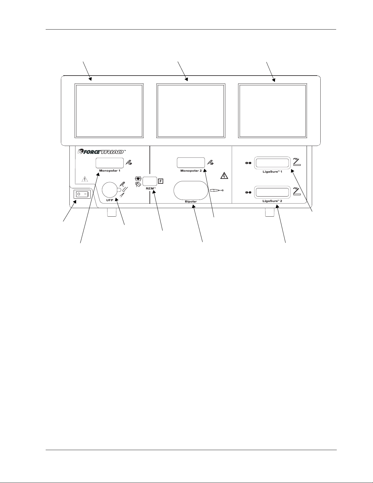
ForceTriad Energy Platform Front Panel
ForceTriad Energy Platform Front Panel
Monopolar 1 and Accessory Touchscreen
Monopolar 2 and Bipolar Touchscreen
LigaSure and System Tray Touchscreen
Power
Switch
Monopolar 1 Instrument Receptacle
Universal Footswitching
Accessory Receptacle
Introduction
List of Components
LigaSure 1
Monopolar 2 Instrument
REM Patient Return
Electrode Receptacle
The ForceTriad energy platform is designed to provide RF energy for monopolar
and bipolar surgical applications and tissue-fusion applications. It features three
touchscreen user interfaces, and has the ability to automatically detect handsets
and configure the generator accordingly. Safety and diagnostic functionality
include automatic fail-safe functions.
The ForceTriad energy platform is a self-contained unit, consisting of a main
enclosure (cover and base) and power cord. The main components are:
• Front panel components
Receptacle
Bipolar Instrument Receptacle
LigaSure 2 Receptacle
Receptacle
• Rear panel components
• Internal components
Details about the interaction of the main components and PCBA descriptions are
provided in Chapter 5, Principles of Operation.
1-2 ForceTriad Service Manual
Page 13
System Conventions
System Conventions
Touchscreens
The ForceTriad energy platform features a user-friendly interface with three
touchscreens that allow the user to control system functions. The active
touchscreen or touchscreens will illuminate, and the unavailable touchscreens will
dim.
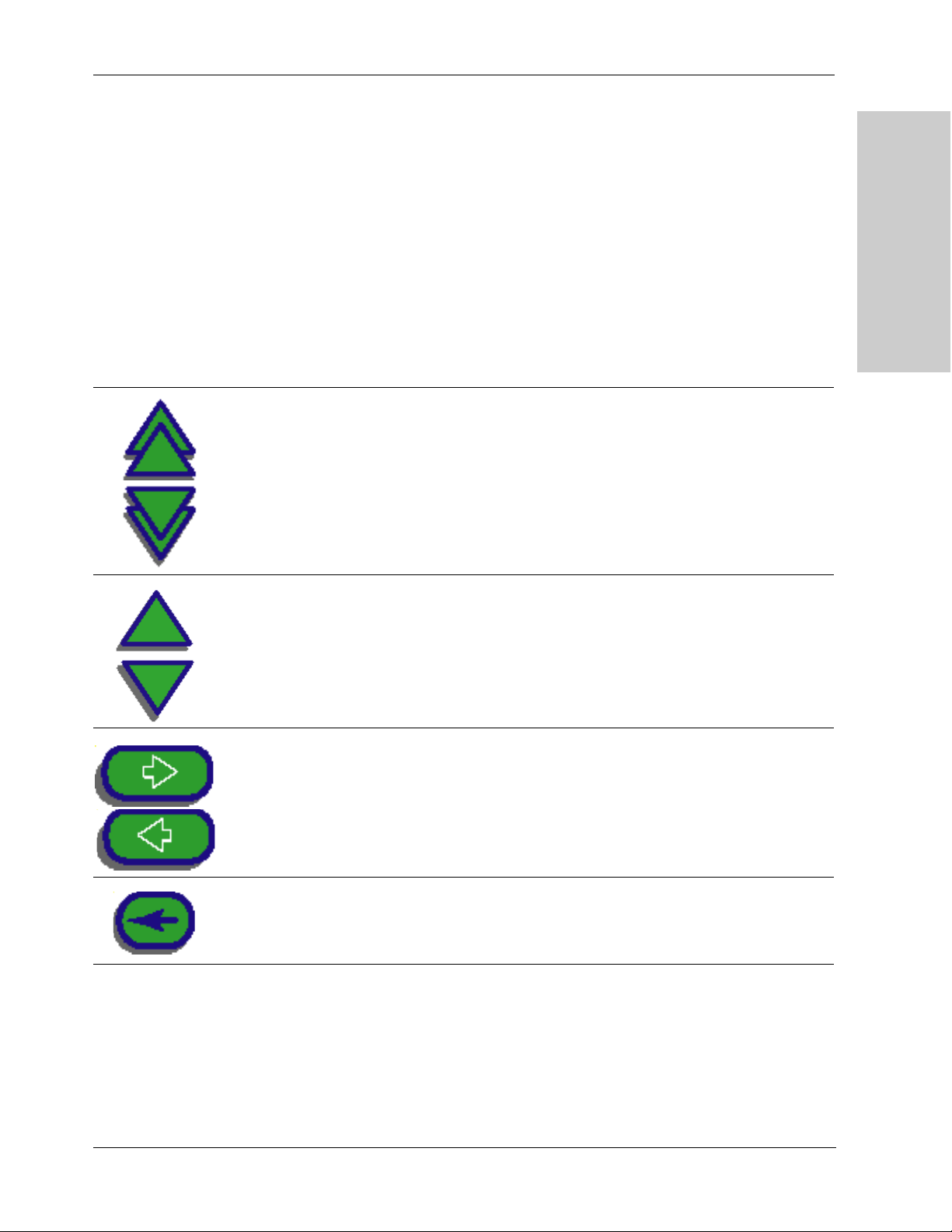
Common Symbols
Symbol Name Description
Page Up/Page Down
Scroll through blocks of options that cannot be displayed on a single
screen.
ForceTriad Energy Platform
Overview and General
Up/Down
Next/Back
Back Space
Pressing once increases/decreases the associated value or moves
highlighted selection up/down one line. Pressing and holding scrolls
up/down.
Progresses/regresses to the next screen.
Regresses one character.
ForceTriad Service Manual 1-3
Page 14
System Conventions
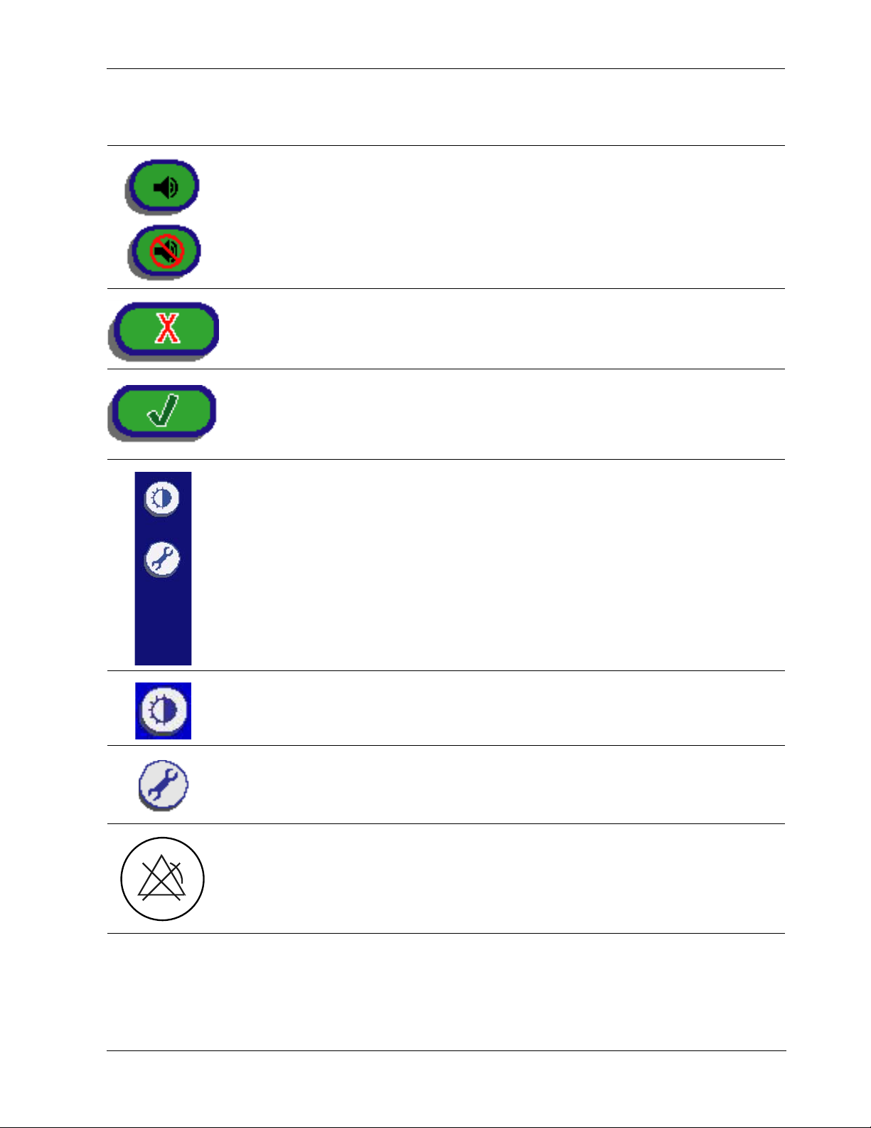
Symbol Name Description
Bipolar Mute On/Off
Cancel
Enter
System Tray
Turn on/off the audio tones produced by the system that indicate the
increase or decrease of current during a bipolar procedure.
Cancels current screen and returns to the previous screen.
Accepts and initiates current selections.
The system tray contains controls that allow you to access and adjust
system settings including screen brightness and main menu options.
Brightness
Each selection of this button adjusts the screen brightness to the next
of the two available brightness settings. When maximum brightness is
reached, next selection resets to the least bright setting.
Wrench
Select access to the main menu, which provides user-selected options
for language, appearance, and operation.
Errors
Disabled
This icon on a yellow background overlays the screen when error
warnings have been disabled using the service menu. The generator
will not alarm or give error conditions when this symbol is activated.
Touching the screen removes the icon for five seconds.
Note: Additional information on symbols may be found in the Technical
Specifications chapter in this manual.
1-4 ForceTriad Service Manual
Page 15

Power Modes
Power Modes
As a safety feature to prevent unexpected power delivery spikes, simultaneous
activation of multiple instruments is not possible on the ForceTriad energy
platform.
Monopolar Modes
The ForceTriad energy platform produces five different modes of power output.
Cut Modes
Pure cut provides a clean, precise cut in any tissue with little or no hemostasis.
Blend cut is a conventional blended waveform that provides slower cutting and
additional hemostasis.
Valleylab Mode
Valleylab mode is a unique combination of hemostasis and dissection and allows
the user to slow down for more hemostasis and speed up for faster dissection.
Thermal spread is equal or superior to Cut or Blend modes.
Coag Modes
Fulgurate coagulates tissue by sparking from the active electrode, through air, to
the patient tissue. Since sparks may spray unpredictably from the electrode during
fulguration, using fulguration for delicate tissue or in confined areas can
complicate surgery. Accidental sparking to adjacent areas can occur as tissue at
the surgical site dries and becomes more resistant to current flow.
Spray delivers wider fulguration; penetration is shallower and the affected tissue
area is larger than with the Fulgurate mode.
ForceTriad Energy Platform
Overview and General
Bipolar Modes
Three bipolar modes are available: Low, Standard, and Macrobipolar.
Low delivers precision and fine control over the amount of desiccation.
Standard is a conventional bipolar output at low voltage.
Macro (Macrobipolar) may be used for bipolar cutting or rapid coagulation.
Power remains constant over a wide range of tissue types.
Autobipolar
The autobipolar feature senses tissue impedance between the two bipolar
electrodes, then uses the impedance information to automatically start or stop
bipolar RF energy delivery. Optionally, the user may choose between footswitch
start and auto start, or program a delay between auto start and RF activation.
Note: When using Autobipolar, the tissue in the grasp of the bipolar device must
have an impedance within 20 Ω and 1,000 Ω. The activation impedance
safety feature will not deliver RF power to the tissue if it is not within the
specified range. This is a factory-set value that cannot be reset by the user.
ForceTriad Service Manual 1-5
Page 16

Power Modes
LigaSure Mode
The LigaSure tissue fusion mode can be used on arteries, veins, pulmonary
vasculature, and lymphatics up to and including 7 mm in diameter and tissue
bundles. This system provides precise energy delivery and electrode pressure to
vessels for a controlled time period to achieve a complete and permanent fusion
of the vessel lumen. The system has been designed to produce minimal sticking,
charring, or thermal spread to adjacent tissue.
Warning
Do not attempt to fuse lung tissue with LigaSure mode or instruments.
LigaSure Instruments
The LigaSure instruments that complete the ForceTriad tissue fusion system
include multiple reusable and single use instruments for open and laparoscopic
procedures. Each reusable instrument requires a corresponding single use
electrode. The LigaSure function is only available when using Valleylab LigaSure
instruments.
1-6 ForceTriad Service Manual
Page 17

Chapter
Patient and Operating Room Safety
The safe and effective use of electrosurgery depends to a large
degree upon factors solely under the control of the operator. There
is no substitute for a properly trained and vigilant surgical team. It is
important that the operating instructions supplied with this or any
electrosurgical equipment be read, understood, and followed.
2
Electrosurgery has been used safely in millions of procedures.
Before starting any surgical procedure, the surgeon should be
trained in the particular technique and surgical procedure to be
performed, should be familiar with the medical literature related to
the procedure and potential complications, and should be familiar
with the risks versus the benefits of utilizing electrosurgery in the
procedure.
ForceTriad Service Manual 2-1
Page 18

General
General
Setting Up the System
Warning
Electric Shock Hazard Connect the system power cord to a properly grounded
power receptacle. Do not use power plug adapters.
Fire Hazard Do not use extension cords.
Patient Safety Use the energy platform only if the power-up self-test has been
completed as described in this manual, otherwise inaccurate power outputs may
result.
Caution
When using a smoke evacuator in conjunction with the ForceTriad energy
platform, set the system volume control at a level that ensures that the activation
tones can be heard.
Connect only Valleylab-approved footswitches. Using footswitches from other
manufacturers may cause equipment malfunction.
Warning
Hazardous Electrical Output This equipment is for use only by trained,
licensed physicians.
Do not use electrosurgical equipment unless properly trained to use it in the
specific procedure being undertaken. Use of this equipment without such training
can result in serious, unintended patient injury, including bowel perforation and
unintended, irreversible tissue necrosis.
Always use the lowest power setting that achieves the desired surgical effect.
The active electrode should be utilized only for the minimum time necessary in
order to lessen the possibility of unintended burn injury. Accidental and
unintended burn injury has occurred during procedures in small surgical fields
and on small appendages. Pediatric applications and/or procedures performed
on small anatomic structures may require reduced power settings. The higher the
current flow and the longer the current is applied, the greater the possibility of
unintended thermal damage to tissue, especially during use on small structures.
Do not wrap the instrument cords or patient return electrode cords around metal
objects. This may induce currents that could lead to shocks, fires, or injury to the
patient or surgical team.
Electric Shock Hazard Do not connect wet instruments to the energy platform.
Ensure that all instruments and adapters are correctly connected and that no
metal is exposed at any connection points.
Confirm proper power settings before proceeding with surgery. If the proper
power settings are not known, set the power to a low setting and cautiously
increase the power until the desired effect is achieved. If increased power
settings are requested, check the patient return electrode and all instrument
connections before major power setting adjustments.
2-2 ForceTriad Service Manual
Page 19

General
Warning
Contact between the active electrode and any metal will greatly increase current
flow and can result in unintended surgical effect.
While using electrosurgery, the patient should not be allowed to come into direct
contact with grounded metal objects (e.g., surgical table frame, instrument table,
etc.). If this is not possible during certain procedures (e.g., those in which
noninsulated head frames are used), use extreme caution to maximize patient
safety:
• Use the lowest power setting that achieves the desired effect.
• Place the patient return electrode as close to the surgical site as possible.
• Place dry gauze between the patient and the grounded object if possible.
• Continually monitor the contact point(s).
• Do not use metal needle monitoring electrodes.
Patient and Operating Room
Caution
Read all warnings, cautions, and instructions provided with this energy platform
before using.
Read the instructions, warnings, and cautions provided with electrosurgical
instruments before using. Specific instructions for electrosurgical instruments are
not included in this manual.
For surgical procedures where the current could flow through delicate parts of the
body, the use of bipolar techniques may be desirable in order to avoid unwanted
coagulation.
Examine all instruments and connections to the system before using. Ensure that
the instruments function as intended. Improper connection may result in arcs,
sparks, instrument malfunction, or unintended surgical effects.
Do not turn the activation tone down to an inaudible level. The activation tone
alerts the surgical team when the energy platform is delivering RF energy.
A non-functioning ForceTriad energy platform may cause interruption of surgery.
A backup system should be available for use.
Studies have shown that smoke generated during electrosurgical procedures can
be potentially harmful to patients and the surgical team. These studies
recommend adequately ventilating the smoke by using a surgical smoke
evacuator or other means.
a
Safety
Inadvertent activation may occur while installing, removing, or bending
electrodes. Ensure that the instrument cord is not connected to the ForceTriad
energy platform or that the system is OFF.
a. U.S. Department of Health and Human Services. National Institute for
Occupational Safety and Health (NIOSH). Control of Smoke from Laser/Electric Surgical Procedures. HAZARD CONTROLS, Publication
No. 96-128, September, 1996.
ForceTriad Service Manual 2-3
Page 20

General
Notice
Connect the power cord to a properly grounded power receptacle having the
correct voltage. Otherwise, product damage may result.
Important
If required by local codes, connect the energy platform to the hospital
equalization connector with an equipotential cable.
Fire/Explosion Hazard
Warning
Danger: Explosion Hazard Do not use electrosurgery in the presence of
flammable anesthetics.
Fire Hazard Do not place active instruments near or in contact with flammable
materials (such as gauze or surgical drapes). Electrosurgical instruments that are
activated or hot from use can cause a fire. When not in use, place electrosurgical
instruments in a safety holster or safely away from patients, the surgical team,
and flammable materials.
2-4 ForceTriad Service Manual
Page 21

General
Warning
Fire Hazard Sparking and heating associated with electrosurgery can be an
ignition source. Keep gauze and sponges wet. Keep electrosurgical electrodes
away from flammable materials and oxygen (O
Use of electrosurgery in O
Therefore, take measures to reduce the O
Avoid enriched O
Both O2 and N2O support combustion and may result in fires and burns to
patients or surgical personnel.
If possible, stop supplemental oxygen at least one minute before and during use
of electrosurgery.
Do not activate the energy platform until flammable vapors from skin prep
solutions and tinctures have dissipated.
Avoid the accumulation of naturally occurring flammable gases that may
accumulate in body cavities such as the bowel.
Prevent pooling of flammable fluids and the accumulation of flammable or
oxidizing gases or vapors under surgical drapes or near the surgical site.
Tissue buildup (eschar) on the tip of an active electrode may create embers that
pose a fire hazard, especially in oxygen enriched environments. Keep the
electrode clean and free of all debris.
Facial and other body hair is flammable. Water soluble surgical lubricating jelly
may be used to cover hair close to the surgical site to decrease flammability.
Verify that all anesthesia circuit connections are leak free before and during use
of electrosurgery.
and nitrous oxide (N2O) atmospheres near the surgical site.
2
rich environments increases the risk of fire.
2
) enriched environments.
2
concentration at the surgical site.
2
Patient and Operating Room
Safety
Fire Hazard During Oropharyngeal Surgery
Verify endotracheal tubes are leak free and that the cuff seals properly to prevent
oxygen leaks.
If an uncuffed tube is in use, pack the throat with wet sponges around the
uncuffed tube, and be sure to keep sponges wet throughout the procedure.
Question the need for 100% O2 during oropharyngeal or head and neck surgery.
If necessary, scavenge excess O2 with separate suction.
Energy Platform
Warning
Each instrument receptacle on this energy platform is designed to accept only
one instrument at a time. Do not attempt to connect more than one instrument at
a time into a receptacle. Doing so will cause simultaneous activation of the
instruments. Follow the instructions provided with electrosurgical instruments for
proper connection and use.
Caution
Do not stack equipment on top of the energy platform or place the energy
platform on top of electrical equipment. This is an unstable configuration and
does not allow for adequate cooling.
ForceTriad Service Manual 2-5
Page 22

General
Caution
Provide as much distance as possible between the energy platform and other
electronic equipment (such as monitors). Do not cross or bundle electronic device
cords. This energy platform may cause interference with other electronic
equipment.
Active instruments
Caution
Read the instructions, warnings, and cautions provided with electrosurgical
instruments before using. Specific instructions for electrosurgical instruments are
not included in this manual.
Inspect instruments and cords for breaks, cracks, nicks, and other damage
before every use. If damaged, do not use. Damaged instruments or cords may
result in injury or electrical shock to the patient or surgical team.
Use only instruments that can withstand the maximum output (peak) voltage for
each output mode as listed in the Technical Specifications chapter in this manual.
Using an instrument with a voltage rating that is lower than the maximum output
voltage may result in injury to the patient or the operator, or damage to the
instrument.
All Valleylab instruments have voltage ratings that are greater than the maximum
output voltages in the ForceTriad energy platform and are thus fully compatible.
Information on voltage ratings for non-Valleylab instruments should be obtained
from the instrument’s manufacturer.
Pacemakers and ICDs
Warning
Use electrosurgery and tissue fusion with caution in the presence of internal or
external pacemakers. Interference produced by the use of electrosurgical
devices can cause a pacemaker to enter an asynchronous mode or can block the
pacemaker effect entirely. Consult the pacemaker manufacturer or hospital
cardiology department for further information when use of electrosurgery or
tissue fusion appliances is planned in patients with cardiac pacemakers.
If the patient has an implantable cardioverter defibrillator (ICD), contact the ICD
manufacturer for instructions before performing an electrosurgical or tissue fusion
procedure. Electrosurgery or tissue fusion may cause multiple activations of
ICDs.
2-6 ForceTriad Service Manual
Page 23

Monopolar
After Surgery
Warning
Electric Shock Hazard Always turn off and unplug the energy platform before
cleaning.
Caution
Do not reprocess, reuse or resterilize instruments labeled “disposable” or “single
use only.”
Notice
Do not clean the energy platform with abrasive cleaning or disinfectant
compounds, solvents, or other materials that could scratch the panels or damage
the energy platform.
Patient and Operating Room
Monopolar
Safety
Warning
Simultaneously activating suction/irrigation and electrosurgical current may result
in increased arcing at the electrode tip, burns to unintended tissues, or shocks
and burns to the surgical team.
Some surgeons may elect to “buzz the hemostat” during surgical procedures. It is
not recommended, and the hazards of such a practice probably cannot be
eliminated. Burns to the surgeon’s hands are possible. To minimize the risk take
these precautions:
• Do not “buzz the hemostat” with a needle electrode.
• Do not lean on the patient, the table, or the retractors while buzzing the
hemostat.
• Activate cut rather than coag. Cut has a lower voltage than coag.
• Firmly grasp as much of the hemostat as possible before activating the energy
platform. This disperses the current over a larger area and minimizes the
current concentration at the finger tips.
• “Buzz the hemostat” below hand level (as close as possible to the patient) to
reduce the opportunity for current to follow alternate paths through the
surgeon’s hands.
• Use the lowest power setting possible for the minimum time necessary to
achieve hemostasis.
• Activate the energy platform after the instrument makes contact with the
hemostat. Do not arc to the hemostat.
• When using a coated or nonstick blade electrode, place the edge of the
electrode against the hemostat or other metal instrument.
ForceTriad Service Manual 2-7
Page 24

Monopolar
Patient Return Electrodes
Warning
Do not attempt to use patient return electrodes that disable the REM system. The
ForceTriad energy platform’s REM system will function correctly only with contact
quality monitoring (CQM) split-style patient return electrodes. Any other patient
return electrode products may cause patient injury or product damage.
The safe use of monopolar electrosurgery requires proper placement of the
patient return electrode. To avoid electrosurgical burns beneath the patient return
electrode, follow all directions provided with the product.
Do not cut a patient return electrode to reduce its size. Patient burns due to high
current density may result.
A patient return electrode is not necessary in bipolar or LigaSure procedures.
To avoid patient burns, ensure that the patient return electrode firmly and
completely contacts the skin. Always check the patient return electrode
periodically and after the patient is repositioned and during procedures involving
long periods of activation.
Use of duty cycles greater than 25% (10 seconds active followed by 30 seconds
inactive) will increase the risk that heat build-up under a return electrode may be
high enough to injure the patient. Do not continuously activate for longer than one
minute.
Notice
Capacitive pads and other non-CQM patient return electrodes may not work with
the ForceTriad energy platform.
Important
A statement of compatibility from the CQM patient return electrode manufacturer
should be obtained prior to the use of a non-Valleylab CQM patient return
electrode.
Inadvertent Radio Frequency (RF) Burns
Warning
Electrodes and probes used with monitoring, stimulation, and imaging devices (or
similar equipment) can provide a path for high frequency current even if the
electrodes or probes are isolated at 50-60 Hz, insulated, and/or battery operated.
Do not use needles as monitoring electrodes during electrosurgical procedures.
Inadvertent electrosurgical burns may result.
To reduce the risk of an inadvertent electrosurgical burn at the electrode or probe
site, place the electrode and/or probe as far away as possible from the
electrosurgical site and/or patient return electrode. Protective impedances
(resistors or RF inductors) installed in the monitoring leads may reduce the risk of
such burns. Consult the hospital biomedical engineer for further information.
2-8 ForceTriad Service Manual
Page 25

Bipolar
Warning
In some circumstances, the potential exists for alternate site burns at points of
skin contact (e.g., between the arm and the side of the body). This occurs when
electrosurgical current seeks a path to the patient return electrode that includes
the skin-to-skin contact point. Current passing through small skin-to-skin contact
points is concentrated and may cause a burn. This is true for ground referenced
and isolated output electrosurgical energy systems.
To reduce the potential for alternate site burns, do one or more of the following:
• Avoid skin-to-skin contact points, such as fingers touching leg or knee touching
knee when positioning the patient.
• Place insulation, such as dry gauze or towel, between contact points to ensure
that contact does not occur.
• Position the patient return electrode to provide a direct current route between
the surgical site and the return electrode which avoids skin-to-skin contact
areas.
• In addition, place patient return electrodes according to the manufacturer’s
instructions.
Patient and Operating Room
Safety
Bipolar
LigaSure
Caution
Bipolar instruments must be connected to the bipolar instrument receptacle only.
Improper connection may result in inadvertent system activation.
Warning
LigaSure instruments are intended for use ONLY with the Valleylab ForceTriad
energy platform and the Valleylab LigaSure vessel sealing system. Use of these
instruments with other Valleylab generators or with generators produced by other
manufacturers may not result in electrical output for which these instruments
were designed and thus may not result in the desired clinical effect.
If the seal cycle complete tone has not sounded, an optimal seal may not have
been achieved. Reactivate the RF energy until a seal complete tone is heard.
The LigaSure tissue fusion function has not been shown to be effective for tubal
sterilization or tubal coagulation for sterilization procedures. Do not use this
function for these procedures.
Use caution during surgical cases in which patients exhibit certain types of
vascular pathology (atherosclerosis, aneurysmal vessels, etc.). For best results,
apply the seal to unaffected vasculature.
Do not activate the energy platform in the LigaSure mode until the tissue fusion
instrument has been applied with the proper pressure. Activating the energy
platform before this is done will result in an improper seal and may increase
thermal spread to tissue outside the surgical site.
ForceTriad Service Manual 2-9
Page 26

LigaSure
Warning
Tissue fusion requires the application of RF energy and pressure from the
instrument. Tissue to be sealed must be firmly grasped between the instrument
jaw electrodes. Tissue in the jaw hinge or outside the instrument jaw will not be
sealed even if thermal blanching occurs.
Do not use LigaSure instruments on vessels in excess of 7 mm in diameter.
LigaSure instruments that require single use electrodes must be used with the
correct electrode type. Use of these instruments with any other electrodes could
result in injury to the patient or surgical team, or cause damage to the instrument.
Conductive fluids (e.g, blood or saline) in direct contact with LigaSure instruments
or in close proximity may carry electrical current or heat, which may cause
unintended surgical effects or burns.
Caution
Energy based devices, such as electrosurgical pencils or ultrasonic scalpels, that
are associated with thermal spread should not be used to transect seals.
Avoid placing fingers in the handle ratchet mechanism. Injury to the user may
result.
LigaSure in Laparoscopic Procedures
Warning
For laparoscopic procedures, be alert to these potential hazards:
• The external surfaces of the LigaSure instrument jaws may remain hot enough
to cause burns after the RF current is deactivated.
• Inadvertent activation or movement of the activated LigaSure instrument
outside of the field of vision may result in injury to the patient.
• Do not activate the instrument while the instrument jaws are in contact with, or
in close proximity to, other instruments including metal cannulas, as localized
burns to the patient or physician may occur.
• Do not activate the LigaSure function in an open circuit condition. Activate the
energy platform only when the instrument is near or in direct contact with the
target tissue to reduce the possibility of unintended burns.
• Carefully insert and withdraw LigaSure instruments from cannulas to avoid
possible damage to the devices and/or injury to the patient.
2-10 ForceTriad Service Manual
Page 27

Servicing
Servicing
Warning
Electric Shock Hazard Do not remove the energy platform cover. Contact
authorized personnel for service.
Notice
Refer to this system’s service manual for maintenance recommendations and
function and output power verification procedures.
Shunt Cords
Warning
Some surgical instruments (e.g., colonoscopes) may allow substantial leakage
current that could burn the surgeon. If the instrument manufacturer recommends
the use of a shunt cord (s-cord) to direct the current back to the energy platform,
you must also use a Valleylab E0507-B adapter. To avoid a REM alarm, you must
use a REM patient return electrode with the E0507-B adapter.
Procedures Where Conductive Fluid is Introduced into the Surgical Site
Warning
When this energy platform is used in procedures where conductive fluid (saline or
lactated Ringers) is introduced into the surgical site for distention or to conduct
RF current, higher than normal currents (greater than one amp) may be
produced. In this situation, use one or more adult-size return electrodes. Do not
use return electrodes labeled for children, infants, babies, neonatal use, or
pediatric use.
Use of duty cycles greater than 25% (10 seconds active followed by 30 seconds
inactive) will increase the risk that heat build-up under a return electrode may be
high enough to injure the patient. Do not continuously activate for longer than one
minute.
Patient and Operating Room
Safety
ForceTriad Service Manual 2-11
Page 28

Laparoscopic Procedures
Laparoscopic Procedures
Warning
For laparoscopic procedures, be alert to these potential hazards:
• Laparoscopic surgery may result in gas embolism due to insufflation of gas in
the abdomen.
• The electrode tip may remain hot enough to cause burns after the
electrosurgical current is deactivated.
• Inadvertent activation or movement of the activated electrode outside of the
field of vision may result in injury to the patient.
• Localized burns to the patient or physician may result from electrical currents
carried through conductive objects (such as cannulas or scopes). Electrical
current may be generated in conductive objects through direct contact with the
active electrode, or by the active instrument (electrode or cable) being in close
proximity to the conductive object.
• Do not use hybrid trocars that have a non-conductive locking anchor placed
over a conductive sleeve. For the operative channel, use all metal or all plastic
systems. At no time should electrical energy pass through hybrid systems.
Capacitive coupling of RF current may cause unintended burns.
• When using laparoscopic instrumentation with metal cannulas, the potential
exists for abdominal wall burns to occur due to direct electrode contact or
capacitive coupling of RF current. This is most likely to occur in instances
where the energy platform is activated for extended periods at high power
levels inducing high current levels in the cannula.
• Ensure that the insulation of single use and reusable laparoscopic
instrumentation is intact and uncompromised. Compromised insulation may
lead to inadvertent metal-to-metal sparking and neuromuscular stimulation
and/or inadvertent sparking to adjacent tissue.
• Do not activate electrodes while in contact with other instruments as
unintended tissue injury may occur.
Do not activate the energy platform in an open circuit condition. To reduce the
chances of unintended burns, activate the energy platform only when the active
electrode is near or touching the target tissue.
• Use the lowest power setting that achieves the desired surgical effect and use
a low voltage waveform (Pure Cut, Blend, or Valleylab mode) to lessen the
potential for the creation of capacitive currents.
• Carefully insert and withdraw active electrodes from cannulas to avoid possible
injury to the patient or damage to the devices.
Valleylab recommends against the use of laparoscopic surgery on pregnant
patients.
2-12 ForceTriad Service Manual
Page 29

System Setup
This chapter describes the how to set up the energy platform, turn it
on, and configure system settings.
Read all warnings, cautions, and instructions provided with this system before
use.
Chapter
3
Caution
Read the instructions, warnings, and cautions provided with electrosurgical
instruments before use. Specific instructions for electrosurgical instruments are
not included in this manual.
ForceTriad Service Manual 3-1
Page 30

Setup
Setup
Before Startup
1. Verify the system is off by pressing the power switch off (O).
2. Place the energy platform on a flat, stable surface such as a table, platform,
boom system, or Valleylab cart. Carts with conductive wheels are
recommended. Refer to the procedures for your local institution or your local
codes.
3. Plug the system power cord into the rear panel receptacle.
4. Plug the system power cord into a grounded power receptacle.
Note: Do not plug into a power strip or extension cord.
Powering Up the ForceTriad Energy Platform
1. Turn on the system by pressing the power switch on ( | ). Observe the
following during the power-up self test:
• The ForceTriad logo will appear on all three screens.
System Functions
• A status bar indicates activity.
• An hourglass icon indicates activity after the status bar disappears.
• A tone will sound upon completion of self-test.
2. If the system does not pass the power-up self test, refer to Chapter 7,
Troubleshooting.
Adjusting Display Brightness
The ForceTriad energy platform screens have two levels of brightness. Touch the
brightness icon on the right side of the right touchscreen to adjust the display
brightness.
The high and low brightness settings can be changed in Brightness Calibration as
explained on page 6-19.
Activation Log
The Activation Log allows the user to view the last 1000 activations and REM
alerts.
1. Touch the wrench icon on the right side of the right touchscreen. The main
menu display will appear in the left touchscreen.
2. T ouch Activation Log in the main menu. The activation log will appear on the
center touchscreen.
3. Touch the single up or down arrows to the right of the activation log to scroll
through the log one line at a time.
3-2 ForceTriad Service Manual
Page 31

System Functions
4. Touch the green arrow button on the bott om right corner of the m a in menu
screen to return the ForceTriad energy platform to the previous setup
configuration. The last settings will be displayed.
Service Display
Refer to “Maintenance and Repair” on page 9-1 for complete service instructions.
Restore
Select the Restore button in the main menu to restore the ForceTriad energy
platform to the previous setup configuration. The touchscreens will display the
last settings entered prior to shutting the system off.
Setup
The setup menu allows the user to change the language that the system
touchscreens display, set the time and date, and enable or disable the Autobipolar
mode.
Language Setup
1. Touch the wrench icon on the right side of the right touchscreen. The main
menu display will appear in the left touchscreen.
2. Touch Setup in the main menu. The setup display will appear in the left
touchscreen.
3. Touch Language in the setup menu. A list of languages wil l appear in the left
touchscreen.
4. T ouch the single up or down arrows to the right of the list to scroll through the
list one line at a time.
or
Touch the double up or down arrows to scroll through the list one page at a
time.
5. Touch the desired language. A confirmation box will appear and request the
user to confirm that a language change is desired.
6. T o proceed with the language change, touch the green check mark button. The
language will be activated and the confirmation box will close.
or
To reject the language change, touch the red ‘X’ butto n. The language setti ng
will return to the previously selected language.
7. Touch the green arrow button to return to the setup menu.
System Setup
8. Touch the green arrow button below the setup menu to return to the main
menu.
ForceTriad Service Manual 3-3
Page 32

System Functions
Time and Date Setup
1. Touch the wrench icon on the right side of the right touchscreen. The main
menu display will appear in the left touchscreen.
2. Touch Setup in the main menu. The setup display will appear in the left
touchscreen.
3. T ouch the Time and Date button in the setup menu. The time and date display
will appear in the left touchscreen.
4. Touch the desired numeric field (minutes, seconds, month, day, or year) to
select that field.
5. Touch the up or down arrows next to the time or date row to adjust the
selected numeric field.
T ouch and hold the arrows to increase the number once per second. After four
seconds, the numbers will increase once per 100 milliseconds.
6. T ouch the green check mark button to store the date and time information and
return to the setup menu.
or
Touch the red ‘X’ button to return the time and date to the previous settings
and return to the setup menu.
7. Touch the green arrow button below the setup menu to return to the main
menu.
Enable/Disable Autobipolar
1. Touch the wrench icon on the right side of the right touchscreen. The main
menu display will appear in the left touchscreen.
2. Touch Setup in the main menu. The setup menu will appear in the left
touchscreen.
3. If the Autobipolar mode is not enabled, the Autobipolar button will display
‘Enable Autobipolar’. Touch the Enable Autobipolar button to enable the
Autobipolar mode.
If the Autobipolar mode is enabled, the Autobipolar button will display
‘Disable Autobipolar’. Touch the Disable Autobipolar button to disable the
Autobipolar mode.
4. Touch the green arrow button below the setup menu to return to the main
menu.
3-4 ForceTriad Service Manual
Page 33

System Functions
Demo Mode
Warning
Demo mode is intended for demonstration purposes only. Demo mode is not
intended for clinical use.
Touch the wrench icon on the right side of the right touchscreen. The main menu
display will appear in the left touchscreen.
Enable Demo Mode
1. In the main menu, the Demo mode button will display ‘Enter Demo’ if the
system is not in Demo mode. Touch the Enter Demo mode button to begin
Demo mode. The system operating displays will appear in all the touchscreens
with the words ‘DEMO MODE: Not for Clinical Use’ on all three screens.
Note: Touching the Demo mode screen will remove it briefly from all
touchscreens.
Proceed with any practice or demonstration scenarios. While in Demo mode,
2.
the REM alarm and the dual instrument error alarm are deactivated but RF
power will still be delivered.
Note: In Demo mode the generator will not sense instrument type, so the
appropriate tab must be selected manually for the connected instrument.
To exit Demo mode, either turn the system off and restart it, or follow the
3.
steps in the Exit Demo Mode section as follows.
Exit Demo Mode
1. Touch the wrench icon on the right side of the right touchscreen. The main
menu display will appear in the left touchscreen.
2. In the main menu, the Demo mode button will display ‘Exit Demo’ if the
system is in Demo mode. Touch the Exit Demo button in the main menu to
exit the Demo mode. The system touchscreens will display the last settings
entered during the Demo mode.
System Setup
ForceTriad Service Manual 3-5
Page 34

3-6 ForceTriad Service Manual
Page 35

Technical Specifications
All specifications are nominal and subject to change without notice.
A specification referred to as “Typical” is within ± 20% of a stated
value at room temperature (25° C / 77° F) and a nominal line input
voltage.
Chapter
4
Caution
Read all warnings, cautions, and instructions provided with this system before
use.
Read the instructions, warnings, and cautions provided with electrosurgical
instruments before use. Specific instructions for electrosurgical instruments are
not included in this manual.
ForceTriad Service Manual 4-1
Page 36

Performance Characteristics
Performance Characteristics
General
Output configuration Isolated output
Cooling Natural convection and fan
Display Three LCD touchscreens
Connector ports LED illuminated Smart connector readers
Mounting • ForceTriad energy platform cart (FT900),
Universal Mounting cart (UC8009), and/or the
UC8010 Overshelf
• Operating room boom systems
• Any stable, flat surface such as a table or cart top
Dimensions and Weight
Width 45.8 cm (18 in.)
Depth 50.8 cm (20 in.)
Height 25.5 cm (10 in.)
Weight 13.6 kg (30 lbs)
4-2 ForceTriad Service Manual
Page 37

Operating Parameters
Performance Characteristics
Ambient temperature
range
Relative humidity 30% to 75% non-condensing
Atmospheric pressure 700 millibars to 1060 millibars
Warm-up time If transported or stored at temperatures outside the
+10° C to +40° C
operating temperature range, allow one hour for the
energy platform to reach room temperature before
use.
Transport and Storage
Ambient temperature
range
Relative humidity 25% to 85% (non-condensing)
-30° C to +65° C
Atmospheric pressure 500 millibars to 1060 millibars
Duration of storage The ForceTriad energy platform may be stored
indefinitely. If the energy platform is stored for over
one year, the memory battery must be replaced.
Internal Memory
Nonvolatile, batterybacked RAM
Storage capacity 256 KB
Battery type: Lithium
Battery life: 120 mAh
Technical Specifications
ForceTriad Service Manual 4-3
Page 38

Performance Characteristics
Activation Tone
The audio levels stated below are for activation tones (cut, Valleylab, coag,
bipolar, and LigaSure modes) and alarm tones (REM and system alarms) at a
distance of one meter.
Volume (adjustable) 45 to 65 dBA
Frequency Cut: 660 Hz
Valleylab: 800 Hz
Coag: 940 Hz
Bipolar: 940 Hz
LigaSure: 440 Hz
Duration Continuous while the system is activated
Alarm Tone
Vo lume (not adju st able) >65 dBA
Frequency REM: 660 Hz
Reactivate/Regrasp, Check Instrument: Two tones:
High = 985 Hz, Low = 780 Hz
Seal Complete: 985 Hz
Error/System Alert: Beep tone = 1421 Hz
Duration REM: Two 1/ 2 second tones separated by 1/2
second for each REM event
Reactivate/Regrasp: Four 175 ms tones — high, low,
high, low
Check Instrument: Six 175 ms tones — high, low,
high, low, high, low
Seal Complete: Two 175 ms tones separated by 175
ms for each Seal Complete event
Error/System Alert: Three 250 ms tones separated by
250 ms for each Error/System Alert event
4-4 ForceTriad Service Manual
Page 39

Performance Characteristics
REM Contact Quality Monitor
Interrogation frequency 80 kHz ± 10 kHz
Interrogation current < 100 µA
Interrogation voltage < 12V RMS
Acceptable Resistance Range
REM resistance measurements are ± 10% during RF activation and ± 5% when
RF output is not activated.
REM patient return electrode: 5 to 135 ohms or up to a 40% increase in the initial
measured contact resistance (whichever is less).
If the measured resistance is outside the acceptable range(s) noted above, a REM
fault condition occurs.
REM Alarm Activation
REM patient return electrode: When the measured resistance exceeds the
standard range of safe resistance (below 5 ohms or above 135 ohms) or when the
initial measured contact resistance increases by 40% (whichever is less), the REM
alarm indicator enlarges and flashes red and yellow, a tone sounds twice, and RF
output is disabled. The indicator remains illuminated red and yellow until you
correct the condition causing the alarm. Then, the indicator illuminates green and
RF output is enabled.
Autobipolar
The ForceTriad energy platform is equipped with an autobipolar feature that
allows for automatic activation of bipolar energy.
Note: The autobipolar electrode function requires the use of the Valleylab
Reusable Footswitching Bipolar Cord E0020V, E0021S, or E0022W.
The autobipolar specifications are:
Interrogation frequency 80 kHz ± 10 kHz
Interrogation current < 100 µA
Interrogation voltage < 12V RMS
Technical Specifications
ForceTriad Service Manual 4-5
Page 40

Performance Characteristics
Activation impedance 20 Ω to 1000 Ω
Deactivation impedance User selectable: 1,500 Ω, 1,800 Ω, 2,000 Ω or
2,200 Ω
Keying delay User selectable in 500 ms increments from
0 sec to 2.5 sec
Measurement accuracy
Inactive
± 5% of Full Scale activation impedance while keying inactive
Active
Mode: BP Low
Load/Power < 30 W
1—500 ohms ± 20% or ±25 ohms
(Whichever is greater)
501—1000 ohms ± 40% ± 20%
1001—2500 ohms +100%/-50% ± 20%
> 2500 ohms Reads > 2200 ohms Reads > 2200 ohms
≥ 30 W
± 20% or ±25 ohms
(Whichever is greater)
Mode: BP Standard
Load/Power < 50 W
1—500 ohms ± 20% or ±25 ohms
(Whichever is greater)
501—1000 ohms ± 40% ± 20%
1001—2500 ohms +100%/-50% ± 20%
> 2500 ohms Reads > 2200 ohms Reads > 2200 ohms
Mode: BP Macro
Load/Power All power levels
1—2500 ohms ± 20% or ±25 ohms
(Whichever is greater)
> 2500 ohms Reads > 2200 ohms
≥ 50 W
± 20% or ±25 ohms
(Whichever is greater)
4-6 ForceTriad Service Manual
Page 41

Performance Characteristics
Duty Cycle
Under maximum power settings and rate d load conditions, the ForceTriad energy
platform is capable of operating a duty cycle of 25%, defined as 10 seconds active
and 30 seconds inactive, in any mode for a period of 4 hours.
Caution
Use of duty cycles greater than 25% (10 seconds active followed by 30 seconds
inactive) will increase the risk that heat build-up under a return electrode may be
high enough to injure the patient. Do not continuously activate for longer than one
minute.
Low Frequency (50/60 Hz) Leakage Current
Enclosure source
current, ground open
Source current, patient
leads, all outputs
Sink current at high
line, all inputs
< 300 µA
Normal polarity, intact ground: < 10 µA
Normal polarity, ground open: < 50 µA
Reverse polarity, ground open: <50 µA
Mains voltage on applied part: < 50 µA
< 50 µA
High Frequency (RF) Leakage Current
Measured with leads
recommended by Valleylab
Bipolar
RF leakage
current
< 59.2 mA
rms
Measured directly at the
energy platform terminals
< 59.2 mA
rms
Monopolar
RF leakage
current
LigaSure
leakage
< 150 mA
<132 mA
rms
rms
< 100 mA
< 100 mA
rms
rms
ForceTriad Service Manual 4-7
Technical Specifications
Page 42

Performance Characteristics
Input Power
100–120 Volt 220–240 Volt
Maximum VA at nominal line voltage:
Idle: 52 VA
Bipolar: 450 VA
Cut: 924 VA
Coag: 530 VA
Input mains voltage, full regulation
range: 90–132 Vac
Input mains voltage, operating range:
85–132 Vac
Mains current (maximum):
Idle: 0.4 A
Bipolar: 2.0 A
Cut: 7.0 A
Coag: 4.0 A
LigaSure: 5.0 A
Mains line frequency range (nominal):
50 Hz to 60 Hz
Maximum VA at nominal line voltage:
Idle: 52 VA
Bipolar: 450 VA
Cut: 924 VA
Coag: 530 VA
Input mains voltage, full regulation
range: 208–264 Vac
Input mains voltage, operating range:
170–264 Vac
Mains current (maximum):
Idle: 0.2 A
Bipolar: 1.0 A
Cut: 3.5 A
Coag: 2.0 A
LigaSure: 2.5 A
Mains line frequency range (nominal):
50 Hz to 60 Hz
Fuses (2): 5 mm x 20 mm 8A, 250 V
fast blow
Power cord: 3-prong hospital grade
connector
Fuses (2): 5 mm x 20 mm 8A, 250 V
fast blow
Power cord: 3-prong locally approved
connector
4-8 ForceTriad Service Manual
Page 43

Performance Characteristics
Power Cord Specification
This unit was equipped from the factory with a 110 VAC hospital grade NEMA
5-15 power cord. Should the AC power cord need to be replaced to match another
plug configuration, the replacement plug/cable/receptacle configuration must
meet or exceed the following specifications:
100-120 VAC
Cable - SJT16/3, IEC color code, maximum length 15 ft (5 m)
Plug - minimum 10 A - 125 VAC
Unit receptacle - IEC female, minimum 10 A - 125 VAC
220-240 VAC
Cable - H05VVF3G1.0 VDE, maximum length 15 ft (5 m)
Plug - minimum 6 A - 250 VAC
Unit receptacle - IEC female, minimum 6 A - 250 VAC
Input Frequency
The ForceTriad energy platform operates within specification at all line inpu t
frequencies between 48 Hz and 62 Hz. The User does not need to reconfigure the
ForceTriad energy platform for different line frequencies.
Input Current
The ForceTriad energy platform draws no more than 10A at any line input
voltage.
Backup Power
The ForceTriad energy platform retains all user programmed features, calibration,
and statistical data when switched off and unplugged. The ForceTriad energy
platform operates within specification when switched over to a supplied line
power by hospital backup systems.
Equipotential Ground Connection
An equipotential ground connection is provided to allow connection of the
ForceTriad energy platform to ground.
ECG Blanking
An ECG blanking port is provided to signal other devices that the ForceTriad
energy platform is active. The receptacle is a 2.5 mm mono jack. It is electrically
isolated from the internal ground referenced electronics with the shell electrically
connected to the chassis for ESD protection.
Technical Specifications
ForceTriad Service Manual 4-9
Page 44

Standards and IEC Classifications
Standards and IEC Classifications
The ForceTriad energy platform meets all pertinent clauses of the IEC 60601-1
second edition and IEC 60601-2-2 third edition.
F
ATTENTION
Consult accompanying documents
The generator output is floating (isolated) with respect to
ground.
DANGER
Explosion risk if used with flammable anesthetics
To reduce the risk of electric shock, do not remove the
cover. Refer servicing to qualified service personnel.
Unit produces non-ionizing radiation
Classified with respect to electrical shock, fire, and
mechanical hazards only in accordance with UL60601-1 and
CAN/CSA C22.2 No. 601.1
4-10 ForceTriad Service Manual
Page 45

Symbols
Symbols
Monopolar instrument receptacle
Monopolar footswitching receptacle
Bipolar instrument receptacle
LigaSure related receptacle or footswitch
Color-coded LigaSure footswitch symbol for matching rear
panel connector to front panel receptacle
REM patient return electrode receptacle
Volume adj ustm e nt for activation tones
Equipotential grounding point
Equipment should not disposed in trash
Technical Specifications
ForceTriad Service Manual 4-11
Page 46

Symbols
Class I Equipment (IEC 60601-1)
Accessible conductive parts cannot become live in the event of a basic insulation
failure because of the way in which they are connected to the protective earth
conductor.
Type CF Equipment (IEC 60601-1)/Defibrillator Proof
This generator provides a high degree of protection against electric
shock, particularly regarding allowable leakage currents. It is type CF
isolated (floating) output and may be used for procedures involving the
heart.
This generator complies with the ANSI/AAMI HF18 specifications for
“defibrillator proof” designation and IEC 60601-2-2.
Liquid Spillage (IEC 60601-2-2 Clause 44.3)
The ForceTriad energy platform is constructed so that liquid spillage in normal
use does not wet electrical insulation or other components which when wetted are
likely to adversely affect the safety of the equipment.
Voltage Transients (Emergency Energy Platform Mains Transfer)
The ForceTriad energy platform continues to operate normally with no errors or
system failures when transfer is made between line AC and an emergency energy
platform voltage source. (IEC 60601-2-2 sub-clause 51.101 and AAMI HF18
sub-clause 4.2.2)
4-12 ForceTriad Service Manual
Page 47

Symbols
Electromagnetic Compatibility (IEC 60601-1-2 and IEC 60601-2-2)
The ForceTriad energy platform complies with the appropriate IEC 60601-1-2
and 60601-2-2 specifications regarding electromagnetic compatibility.
Notice
The ForceTriad energy platform should not be used adjacent to or stacked with
equipment other than specified in the ForceTriad energy platform user guide and
service manual. If adjacent or stacked use is necessary, the ForceTriad energy
platform should be observed to verify normal operation in the configuration in
which it will be used.
The ForceTriad energy platform intentionally applies RF energy for diagnosis or
treatment during activation. Observe other electronic medical equipment in the
vicinity during the ForceTriad energy platform activation for any possible adverse
electromagnetic effects. Ensure adequate separation of electronic medical
equipment based on observed reactions.
The use of accessories, other than specified in the ForceTriad energy platform
user guide and service manual, may result in increased emissions or decreased
immunity of the ForceTriad energy platform.
The ForceTriad energy platform meets the following requirements:
ESD Immunity (IEC 60601-1-2 Sub-Clause 36.202 and IEC 61000-4-2)
Radiated Immunity (IEC 60601-1-2 sub-clause 36.202.2 and IEC 61000-4-3)
Electrical Fast Transient/Burst (IEC 60601-1-2 sub-clause 36.202.3.1 and
IEC 61000-4-4)
Surge Immunity (IEC 60601-1-2 sub-clause 36.202.3.2 and IEC 61000-4-5)
Emissions (IEC 60601-1-2 sub-clause 36.201.1, IEC 60601-2-2 sub-clause 36 and
CISPR 11 Class A)
Harmonic distortion (IEC 60601-1-2 sub-clause 36.201.3.1 and IEC 61000-3-2)
Conducted disturbances (IEC 60601-1-2 sub-clause 36.202.6 and IEC 61000-4-6)
Power frequency magnetic fields (IEC 60601-1-2 sub-clause 36.202.8.1 and
IEC 61000-4-8)
Voltage dips, short interruptions and variations (IEC 60601-1-2 sub-clause
36.202.7 and IEC 61000-4-11)
Technical Specifications
ForceTriad Service Manual 4-13
Page 48

Symbols
Guidance and manufacturer's declaration - electromagnetic emissions
The ForceTriad energy platform is intended for use in the electromagnetic environment specified below. The customer
or the user of the ForceTriad energy platform should assure that it is used in such an environment.
Emissions test Compliance Electromagnetic environment -
guidance
RF emissions
CISPR 11
RF emissions
CISPR 11
Harmonic emissions
IEC 61000-3-2
Voltage fluctuations/ flicker
emissions IEC61000-3-3
Group 2 The ForceTriad energy platform must
emit electromagnetic energy in order
to perform its intended function.
Nearby electronic equipment may be
affected.
Class A The ForceTriad energy platform is
suitable for use in all establishments
other than domestic and those directly
Class A
Complies
connected to the public low-voltage
power supply network that supplies
buildings used for domestic purposes.
4-14 ForceTriad Service Manual
Page 49

Symbols
Guidance and manufacturer's declaration - electromagnetic immunity
The ForceTriad energy platform is intended for use in the electromagnetic environment specified below. The customer
or the user of the ForceTriad energy platform should assure that it is used in such an environment.
Immunity test IEC 60601 test
Electrostatic discharge
(ESD)
IEC 61000-4-2
Electrical fast transient/
burst IEC 61000-4-4
Surge
IEC 61000-4-5
Voltage dips, short
interruptions and voltage
variations on power supply
input lines
IEC 61000-4-11
+/-6 kV contact
+/-2 kV for power
supply lines
+/-1 kV for input/
output lines
+/-1 kV differential
+/-2 kV common
(>95% dip in Ut)
for 0,5 cycle
(>60% dip in Ut)
(>30% dip in Ut)
for 25 cycles
(>95% dip in Ut)
level
+/-8 kV air
mode
mode
< 5 % U t
40 % U t
for 5 cycles
70 % U t
<5 % U t
for 5 sec
Compliance level Electromagnetic environment -
guidance
+/-6 kV contact
+/-8 kV air
+/-2 kV for power
supply lines
+/-1 kV for input/
output lines
+/-1 kV differential
mode
+/-2 kV common
mode
<5% Ut
(>95% dip in Ut)
for 0,5 cycle
40% Ut
(>60% dip in Ut)
for 5 cycles
70% Ut
(>30% dip in Ut)
for 25 cycles
<5% Ut
(>95% dip in Ut)
for 5 sec
Floors should be wood, concrete or
ceramic tile. If floors are covered with
synthetic material, the relative humidity
should be at least 30%.
Mains power quality should be that of a
typical commercial or hospital environment.
Mains power quality should be that of a
typical commercial or hospital environment.
Mains power quality should be that of a
typical commercial or hospital environment.
If the user of the ForceTriad energy
platform requires continued operation
during power mains interruptions, it is
recommended that the ForceTriad energy
platform be powered from an
uninterruptible power supply or a battery.
Power frequency
(50/60 Hz) magnetic field
IEC 61000-4-8
NOTE: Ut is the a.c. mains voltage prior to the application of the test level.
3 A/m 3 A/m Power frequency magnetic fields should be
at levels characteristic of a typical location
in a typical commercial or hospital
environment.
ForceTriad Service Manual 4-15
Technical Specifications
Page 50

Symbols
Guidance and manufacturer's declaration - electromagnetic immunity
The ForceTriad energy platform is intended for use in the electromagnetic environment specified below. The
customer or the user of the ForceTriad energy platform should assure that it is used in such an environment.
Immunity test IEC 60601 test level Compliance level Electromagnetic environment -
guidance
Portable and mobile RF
communications equipment should be
used no closer to any part of the
ForceTriad energy platform, including
cables, than the recommended
separation distance calculated from the
equation applicable to the frequency of
the transmitter.
Conducted RF
IEC 61000-4-6
Radiated RF
IEC 61000-4-3
3 Vrms
150 kHz to 80 MHz
3 V/m
80 MHz to 2.5 GHz
3 V
7 V/m
Recommended separation distance
d=0.5√ P
d=0.5√P 80 MHz to 800 MHz
d=√P 800 MHz to 2.5 GHz
Where P is the maximum output power
rating of the transmitter in watts (W)
according to the transmitter
manufacturer and d is the
recommended separation distance in
meters (m).
Field strengths from fixed RF
transmitters, as determined by an
electromagnetic site survey, should be
less than the compliance level in each
frequency range.
Interference may occur in the vicinity of
equipment marked with the following
symbol:
NOTE 1 At a 80 MHz and 800 MHz, the higher frequency range applies.
NOTE 2 These guidelines may not apply in all situations. Electromagnetic propagation is affected by absorption and
reflection from structures, objects and people.
a. Field strengths from fixed transmitters, such as base stations for radio (cellular/cordless) telephones and land
mobile radios, amateur radio, AM and FM radio broadcast and TV broadcast cannot be predicted theoretically with
accuracy. To assess the electromagnetic environment due to fixed RF transmitters, an electromagnetic site survey
should be considered. If the measured field strength in the location in which the ForceTriad energy platform is used
exceeds the applicable RF compliance level above, the ForceTriad energy platform should be observed to verify
normal operation. If abnormal performance is observed, additional measures may be necessary, such as reorienting
or relocating the ForceTriad energy platform.
b. Over the frequency range 150 kHz to 80 MHz, field strengths should be less than 7 V/m.
4-16 ForceTriad Service Manual
Page 51

Symbols
Recommended separation distances between portable and mobile RF communication equipment and the
ForceTriad energy platform
The ForceTriad energy platform is intended for use in an electromagnetic environment in which radiated RF
disturbances are controlled. The Customer or the user of the ForceTriad energy platform can help prevent
electromagnetic interferences by maintaining a minimum distance between portable and mobile RF communications
equipment (transmitters) and the ForceTriad energy platform as recommended below, according to the maximum
output power of the communications equipment.
Separation distance according to frequency of transmitter (m)
Rated maximum output
power of transmitter (W)
0.01 0.05 m 0.05 m 0.1 m
0.1 0.16 m 0.16 m 0.32 m
1 0.5 m 0.5 m 1 m
10 1.6 m 1.6 m 3.2 m
150 kHz to 80 MHz
d=0.5√P
80 MHz to 800 MHz
d=0.5√P
800 MHz to 2.5 GHz
d=√P
100 5 m 5 m 10 m
For transmitters rated at a maximum output power not listed above, the recommended separation distance d in
meters (m) can be estimated using the equation applicable to the frequency of the transmitter, where P is the
maximum output power rating of the transmitter in watts (W) according to the transmitter manufacturer.
NOTE 1 At 80 MHz and 800 MHz, the separation distance for the higher frequency range applies.
NOTE 2 These guidelines may not apply in all situations. Electromagnetic propagation is affected by absorption and
reflection from structures, objects and people.
Technical Specifications
ForceTriad Service Manual 4-17
Page 52

Output Characteristics
Output Characteristics
Maximum Output for Bipolar, Monopolar, and LigaSure Modes
Power readouts agree with actual power into rated load to within 15% or 5 watts,
whichever is greater.
Mode Open Circuit Peak
Voltage (max)
Bipolar
Low
Standard
Macro
Monopolar Cut
Cut
Blend
Valleylab (HWD) 2365 V 4730 V 300 Ω 200 W 4.3 25%
Monopolar Coag
Fulgurate
Spray
LigaSure 287.5 V 575 V 20 Ω 350 W 1.42 N/A
250 V
175 V
250 V
1050V
1485 V
3050 V
3625 V
Open Circuit P–P
Voltage (max)
500 V
350 V
500 V
2100V
2970 V
6100 V
7250 V
* An indication of a waveform’s ability to coagulate bleeders without a cutting effect.
Rated Load
(max)
100 Ω
100 Ω
100 Ω
300 Ω
300 Ω
500 Ω
500 Ω
Power
(max)
95 W
95 W
95 W
300 W
200 W
120 W
120 W
Crest
Factor*
1.42
1.42
1.42
1.42
2.7
5.55
6.6
Duty
Cycle
N/A
N/A
N/A
N/A
50%
6.5%
4.6%
4-18 ForceTriad Service Manual
Page 53

Output Characteristics
Available Power Settings in Watts
Autobipolar (All Modes)
5678910
11 12 13 14 15 16 17 18 19 20
21 22 23 24 25 26 27 28 29 30
31 32 33 34 35 36 37 38 39 40
45 50 55 60 65 70 75 80 85 90
95
Bipolar (All Modes)
12345678910
11 12 13 14 15 16 17 18 19 20
21 22 23 24 25 26 27 28 29 30
31 32 33 34 35 36 37 38 39 40
45 50 55 60 65 70 75 80 85 90
95
Monopolar Cut
12345678910
11 12 13 14 15 16 17 18 19 20
21 22 23 24 25 26 27 28 29 30
31 32 33 34 35 36 37 38 39 40
45 50 55 60 65 70 75 80 85 90
95 100 110 120 130 140 150 160 170 180
190 200 210 220 230 240 250 260 270 280
290 300
Technical Specifications
ForceTriad Service Manual 4-19
Page 54

Output Characteristics
Monopolar Blend
12345678910
11 12 13 14 15 16 17 18 19 20
21 22 23 24 25 26 27 28 29 30
31 32 33 34 35 36 37 38 39 40
45 50 55 60 65 70 75 80 85 90
95 100 110 120 130 140 150 160 170 180
190 200
Valleylab
12345678910
11 12 13 14 15 16 17 18 19 20
21 22 23 24 25 26 27 28 29 30
31 32 33 34 35 36 37 38 39 40
45 50 55 60 65 70 75 80 85 90
95 100 110 120 130 140 150 160 170 180
190 200
Monopolar Coag
12345678910
11 12 13 14 15 16 17 18 19 20
21 22 23 24 25 26 27 28 29 30
31 32 33 34 35 36 37 38 39 40
45 50 55 60 65 70 75 80 85 90
95 100 110 120
4-20 ForceTriad Service Manual
Page 55

Output Characteristics
Output Waveforms
Tissue Sensing Technology, an automatic adjustment, controls all modes. As
tissue resistance increases from zero, the energy platform outputs constant current
followed by constant power followed by constant voltage. The maximum output
voltage is controlled to reduce capacitive coupling and video interference and to
minimize sparking.
Bipolar
Low 472 kHz sinusoid continuous
Standard 472 kHz sinusoid continuous
Macro 472 kHz sinusoid continuous
Monopolar Cut
Cut 472 kHz sinusoid continuous
Blend 472 kHz bursts of sinusoid, recurring at 26.21 kHz
intervals. 50% duty cycle.
Valleylab
Valleylab 472 kHz bursts of sinusoid, recurring at 28.3 kHz
intervals. 25% duty cycle.
Monopolar Coag
Fulgurate 472 kHz damped sinusoidal bursts with a repetition
frequency of 30.66 kHz. 6.5% duty cycle.
Spray 472 kHz damped sinusoidal bursts with a randomized
repetition centered at 21.7 kHz. 4.6% duty cycle.
Technical Specifications
ForceTriad Service Manual 4-21
Page 56

Output Power vs. Resistance Graphs
Output Power vs. Resistance Graphs
Monopolar Graphs
Pure Cut
Output power versus impedance
for Pure cut power
350
300
250
200
150
100
50
Output power (watts)
0
0 1000 2000 3000 4000 5000
50%
100%
Load Impedance (ohms)
Output power versus power
setting for Pure cut power
Peak voltage versus power
setting for Pure cut power
300
250
200
150
100
Output power (watts)
50
0
0 100 200 300
1200
1000
800
600
400
Peak Voltage
200
0
0 100 200 300
Cut, Output Power
vs . S e t t i n g @
300ohm
Power Setting
Open Circuit Cut
Peak Voltage vs.
Power setting
Power Setting
4-22 ForceTriad Service Manual
Page 57

Output power versus impedance
for Blend power
Output Power vs. Resistance Graphs
Blend
250
200
Output power versus power setting
for Blend power
150
100
Output power (watts)
50
0
0 1000 2000 3000 4000 5000
200
180
160
140
120
100
80
60
Output power (watts)
40
20
0
0 50 100 150 200
50%
100%
Load Impedance (ohms)
Blend Out put P ower
vs . S e t t i ng @
300ohm
Power Setting
Peak voltage versus power setting
Peak Voltage
1600
1400
1200
1000
800
600
400
200
0
0 50 100 150 200
Open Circuit Blend
Peak Volt age vs.
Power Setting
for Blend power
Power Setting
ForceTriad Service Manual 4-23
Technical Specifications
Page 58

Output Power vs. Resistance Graphs
Fulgurate
Output power versus impedance
for Fulgurate power
140
120
100
Output power versus power
setting for Fulgurate power
80
60
40
Output power (watts)
20
0
0 1000 2000 3000 4000 5000
Load Impedance (ohms)
120
100
80
60
40
Output power (watts)
20
0
0 20 40 60 80 100 120
50%
100%
Fulgurate Output
Power vs. Setting
@500ohm
Power Setting
Peak voltage versus power
setting for Fulgurate power
3500
3000
2500
Open Circuit
Fulgurate Peak
Volt age vs. Power
Setting
Peak Voltage
2000
1500
1000
500
0
0 20 40 60 80 100 120
Power Setting
4-24 ForceTriad Service Manual
Page 59

Output power versus impedance
for Spray power
Output Power vs. Resistance Graphs
Spray
140
120
100
Output power versus power setting
for Spray power
80
60
40
Output power (watts)
20
0
0 1000 2000 3000 4000 5000
Load Impedance (ohms)
140
120
100
80
60
40
20
Output power (watts)
0
0 20 40 60 80 100 120
50%
100%
Spray Output Power
vs . S et t i n g @
500ohm
Power Setting
Peak voltage versus power setting
for Spray power
4000
3500
3000
Peak Voltage
2500
2000
1500
1000
500
0
0 20 40 60 80 100 120
Open Circuit Spray
Peak Voltage vs.
Power Setting
Power Setting
ForceTriad Service Manual 4-25
Technical Specifications
Page 60

Output Power vs. Resistance Graphs
Valleylab
Output power versus impedance
for Valleylab power
Output power versus power
setting for Valleylab power
250
200
150
100
Output power (watts)
50
0
0 500 1000 1500 2000 2500 3000 3500 4000 4500
Load Impedance (ohms)
200
180
160
140
120
100
80
60
40
Output power (watts)
20
0
0 50 100 150 200
50%
100%
Hemos tasis w/
Division Output
power vs. Power
Setting @ 300ohm
Power Setting
Peak voltage versus power
setting for Valleylab power
2500
2000
1500
1000
Open Circuit
Valleylab Mode
Peak Voltage vs.
Power Setting
Peak Voltage
500
0
0 50 100 150 200
Power Setting
4-26 ForceTriad Service Manual
Page 61

Output power versus impedance
for Bipolar Low power
Bipolar Graphs
Bipolar Low
100
90
80
70
60
50
40
30
Output power (watts)
20
10
0
0 500 1000 1500 2000 2500
Output Power vs. Resistance Graphs
50%
100%
Load Impedance (ohms)
Output power versus power setting
for Bipolar Low power
Peak voltage versus power setting
for Bipolar Low power
Output power (watts)
Peak Voltage
90
80
70
60
50
40
30
20
10
0
0 20406080
Power Setting
250
200
150
100
50
Bip Low Output
Power vs. Setting @
100ohm
Open Circuit Bipolar
Low Peak Voltage
vs. Power Setting
Technical Specifications
0
0 20406080
Power Setting
ForceTriad Service Manual 4-27
Page 62

Output Power vs. Resistance Graphs
Bipolar Standard
Output power versus impedance
for Bipolar Standard power
Output power versus power
setting for Bipolar Standard power
Peak voltage versus power
setting for Bipolar Standard
power
100
90
80
70
60
50
40
30
Output power (watts)
20
10
0
0 500 1000 1500 2000 2500
90
80
70
60
50
40
30
Output power (watts)
20
10
0
0 20406080
350
300
50%
100%
Load Impedance (ohms)
Bip Std Out put
Power vs. Setting @
100ohm
Power Setting
250
200
150
Peak Voltage
100
50
0
0 20406080
500ohm Bipolar
Standard Peak
Volt age vs. Power
Setting
Power Setting
Note: Maximum peak voltage in the Bipolar Standard mode occurs at 500 Ω, not
open circuit.
4-28 ForceTriad Service Manual
Page 63

Output power versus impedance
for Bipolar Macro power
Output power versus power setting
for Bipolar Macro power
Bipolar Macro
Output power (watts)
90
80
70
60
50
40
30
20
Output power (watts)
10
Output Power vs. Resistance Graphs
100
90
80
70
60
50
40
30
20
10
0
0 500 1000 1500 2000 2500
Load Impedance (ohms)
0
0 2040 6080
Power Setting
50%
100%
Bip Macro Output
Power vs. Setting @
100ohm
Peak voltage versus power setting
for Bipolar Macro power
250
200
150
100
Open Circuit Bipolar
Macro Peak V oltage
vs. Power Setting
Peak Voltage
50
0
0 20406080
Power Setting
ForceTriad Service Manual 4-29
Technical Specifications
Page 64

Output power versus impedance
0
for LigaSure power
Peak voltage versus impedance
for LigaSure power
LigaSure
200
180
160
140
120
100
80
60
40
Output power (watts)
20
0
0 100 200 300 400 500
250
200
150
Load Impedance (ohms)
100
Peak Voltage
50
0
0 100 200 300 400 500 60
Load Impedance (ohms)
4-30 ForceTriad Service Manual
Page 65

Output Power vs. Resistance Graphs
ForceTriad Service Manual 4-31
Technical Specifications
Page 66

Output Power vs. Resistance Graphs
4-32 ForceTriad Service Manual
Page 67

Principles of Operation
This chapter provides detailed information about how the
ForceTriad energy platform functions and how the internal
components interact.
Chapter
5
This chapter includes the following information:
• A block diagram that illustrates how the energy platform functions
• A general description of how the generator works
• Detailed descriptions of the circuitry for the printed PCBAs
ForceTriad Service Manual 5-1
Page 68

Block Diagram
Block Diagram
REM
Power
Switch
RF Out
Monopolar 1
Fan
Scanner
Monopolar 2
Front Panel
Fan
RF Out
Scanner
Fan
(UFP)
Footswitch Output
Fan
Control
VS 1
RF Out
Iso-block
Monopolar output1/
VS 2
Scanner
Iso-block
Monopolar output 2/
RF Out
Scanner
UFP Output
Output
Bipolar
Board
Steering Relay
LCD
Display Board
Iso-block
VS output 1/
Display w/
touchscreen
+5v
UART
VS output1/
LCD
GND
Iso-block
Bipolar output/
Display w/
touchscreen
+3.3
Iso-block
LCD
Display w/
touchscreen
+1.8
FPGA
AC Line
Switched
Ground
Chassis
In
HVPS
GND
5,+12,-12
HV F.B
Control
line switching)
(HV Generation, Auto
AC LVPS
Switched
Line
Power Entry AC
AC Line
LVPS
REM
DAC
GND
+5, +12, -12
Sense
PS Control
HVPS
LVPS
Control
REM
5
Signals
GND
5, +12,-12
GND
RS 232
RS 232
stage
RF output
RF Board
HV
Control
Sensor Circuit
Controller
DAC
RF Control
Control
Footswitch
Scanner
+3.3
ADC
USB
Ethernet
Footswitch/
handswitch contol
W/
Touch
screen
Display
Audio
+1.8
Lines routed thru RF Board
Footswitch/ Audio
USB
Ethernet
Footswitches
5-2 ForceTriad Service Manual
Page 69

Functional Overview
Functional Overview
Principles of Operation
The ForceTriad energy platform is a combination of a full-featured general
surgery electrosurgical unit and a LigaSure vessel sealing system. The monopolar
and bipolar sections of the ForceTriad are isolated electrosurgical outputs that
provide the appropriate power for cutting, desiccating, and fulgurating tissue
during monopolar and bipolar surgery. The LigaSure section of the ForceTriad
provides power for vessel sealing.
During monopolar electrosurgery, radio frequency (RF) current flows from the
generator to an active electrode, which delivers the current to the patient. The
resistance to the current, provided by the patient’s tissue and/or the air between
the active electrode and the tissue, produces the heat that is necessary for the
surgical effect. The RF current flows from the active electrode, through the
patient’s body tissue to the return electrode, which recovers the current and
returns it to the generator.
The LigaSure vessel sealing system provides precise energy delivery and
electrode pressure to vessels for a controlled time period to achieve a complete
and permanent fusion of the vessel lumen.
TissueFect Tissue Sensing Technology
The ForceTriad energy platform automatically senses resistance and adjusts the
output voltage to maintain a consistent tissue effect across different tissue
impedance. This adjustment is based on the selected mode, the power setting, and
the level of tissue resistance.
REM Contact Quality Monitoring System
The ForceTriad energy platform uses the Valleylab REM Contact Quality
Monitoring system to monitor the quality of electrical contact between the patient
return electrode and the patient. The REM system is designed to minimize the risk
of burns at the return electrode site during monopolar electrosurgery.
When you connect a REM patient return electrode to the Patient Return Electrode
receptacle, you activate the REM system. When you activate monopolar output,
the generator connects the patient return electrode path. If you activate bipolar
output while a return electrode is connected to the patient, the return electrode
circuit is deactivated automatically to eliminate the possibility of current
dispersal.
The REM system continuously measures resistance at the return electrode site and
compares it to a standard range of safe resistance (between 5 and 135 ohms), thus
minimizing intermittent false alarms that could result from small changes in
resistance. The REM system also adapts to individual patients by measuring the
initial contact resistance (baseline resistance) between the patient and the patient
return electrode. If the tissue impedance at the return electrode decreases during
electrosurgery, the REM system resets the baseline resistance.
ForceTriad Service Manual 5-3
Page 70

High Voltage DC (HVDC) Power Supply Principles of Operation
REM Alarm Activation
The REM Alarm indicator flashes red, a tone sounds, and the generator stops
producing output power when either of the following occurs:
• The measured resistance is below 5 ohms or above 135 ohms, the limits of the
standard range of safe resistance.
• An increase in contact resistance is greater than 40% from the initial
measurement (baseline resistance).
The REM Alarm indicator remains illuminated red until you correct the condition
causing the alarm. Then, the indicator illuminates green and RF output is enabled.
Electrodes Without the REM Safety Feature
Return electrodes without the REM safety feature cannot be used on the
ForceTriad energy platform.
High Voltage DC (HVDC) Power Supply Principles of Operation
The HVDC power supply will regulate an output DC voltage to a desired level
that is proportional to a 0 to 5V analog logic signal called Voltage Control
(ECON). The AC input range is 85VAC to 264VAC with line frequencies from
47Hz to 63Hz. The HVDC can be simplified into two sections, the AC section
and DC section.
The AC section rectifies the AC input into the rectified +Bus and –Bus voltages.
For line voltages of 150VAC or less, the rectified AC voltage is doubled. The
rectified voltage is monitored and will be flagged if the voltage starts to drop too
low or if the rectified voltage exceeds 400VDC. As a safety feature, the HVDC
will be shut down when it exceeds 400VDC. The AC section also incorporates a
soft start circuit that will reduce the inrush AC current at power up.
The DC section is a phase-shifted full-bridge typology and uses a Pulse Width
Modulator (PWM) from Texas Instruments, part number UCC3895. For
information on this particular typology, the data sheet (available at ti.com) for
this part contains a full dialogue of the theory of operation. The DC section
consists of limits that help protect the HVDC from fault conditions. These limits
include over voltage, over current, over power, and short circuit. Each limit sends
a flag to the controller card if it is triggered and will shut down the HVDC.
Another feature of the HVDC is an active discharge circuit; this circuit will place
a load across the output. This allows the output of the HVDC to discharge quickly
no matter what the load attached to the HVDC.
5-4 ForceTriad Service Manual
Page 71

RF Principles of Operation
The primary purpose of the ForceTriad RF PCBA is to convert the DC voltage
coming from the HVDC PCBA into a 470 kHz RF signal that is sent to the
Steering Relay PCBA to be distributed to the appropriate output. A push-pull
typology is used to accomplish this voltage conversion. Two gate drive signals
that are 180° out of phase are used to drive the high voltage Field Effect
Transistors (FETs), called T ON and T ON 180. The gate drive signals turn on
each of the FETs at opposite times to deliver a waveform at the specified power
requested from the user. The RF PCBA is capable of several different outputs
ranging from 5.5Arms in LigaSure tissue fusion modes to over 7KVpp in coag
modes. Relays throughout the RF PCBA switch in the appropriate tuning
elements required to achieve these various outputs.
Primary and redundant sense circuits detect the RF output voltage and current. An
accurate scaled down AC voltage representative of each of these is sent to the
Controller PCBA, which in turn will keep the output at levels appropriate for the
mode in use. Four sense relays per circuit correspond to specific modes and
switch in voltage dividers tuned to divide the output signals to levels that are
manageable for the Controller card. Three relays per voltage sense circuit divide
down the output voltages from 425Vpk - 5000Vpk to around 1Vpk, depending on
the mode selected by the user. The current sensors use 1 relay per circuit; this
relay kicks in for currents higher than 1Arms. The sensor signals are passed
through a multiplier which uses a gain control signal from the controller card.
After this multiplier stage, the signal is filtered and routed to the controller card.
RF voltage and current foldback circuits use the ranges selected on the sensors to
determine if a limit has been hit. These circuits will fold back the ECON signal
going to the HVDC, reducing the DC output to the RF PCBA. This in turn reduces
the RF output amplitude.
RF Principles of Operation
Principles of Operation
REM
The Return Electrode Monitor (REM) circuit monitors the resistance between the
two return areas on a REM electrode using a 80 kHz signal generated by the
controller card.
Autobipolar
The Autobipolar (ABP) circuit consists of an 80 kHz signal, also generated by the
controller card. It is used to monitor the bipolar output impedance.
Leakage Current Monitor
The RF PCBA also features a leakage current monitor circuit, which measures the
active and return of the generator and puts out a DC voltage that represents the
difference between the two. If this voltage exceeds a limit, the RF will be folded
back to prevent excess leakage current.
ForceTriad Service Manual 5-5
Page 72

RF Principles of Operation
Sensor Circuit
The sensor circuit provides RF output voltage and current monitoring to software
in order to deliver the correct energy dosage during a surgical procedure. Two
identical sensory circuit paths, composed of a primary and backup, are
implemented to provide fail-safe mitigation in the event of circuit failure. Since
each primary and backup sensor circuit mirrors the other, the sensed output
voltages, which are monitored by software, are equal when the sensory system
maintains proper operation. In the event of primary or backup sense circuit
failure, dissimilar outputs are present and software detection stops delivery of RF
and notifies the user with an error message displayed on the front panel of the
ForceTriad energy platform.
Each primary and backup sensory circuit consists of four processing elements to
ensure that the correct RF is delivered. In the description that follows, the primary
sensory path is identified for the voltage sense circuitry, with reference
designation only provided to the backup circuit. Backup circuit operation is
identical to the primary circuit that is described here. RF current sense circuit
process is symmetrical to the voltage sense description in that it also uses four
processing elements. The only notable difference between voltage and current
sensing is the different transfer gains required to adequately address the dynamic
range of individual generator operating modes.
First: Transformer T6, along with resistors R110 and R119, provide RF output
voltage monitoring by generating a proportionatel y scal ed, secondary sense
voltage, which is correlated to the delivered RF output voltage. Backup
referenced components are T1, R95, and R111.
Second: Coupled to the secondary of transformer T6, a software controlled
switched pad network is implemented to provide proper impedance scaling to
address the dynamic sensory range required for all operating modes of the
ForceTriad energy platform. This pad impedance switched network is used to
develop the proportionately scaled secondary sense voltage of T6. Resistors R103
and R107 provide the initial impedance termination, paralleled by resistor paired
components R104 and R105, R94 and R106, and R85 and R100, which are
switched independent on the selected generator Cut, Blend, and Coag operating
modes respectively. Paired resistor switching is accomplished by electronic
switch components RL12, RL11, and RL10 respectively. Backup referenced
terminating components are R89 and R93; paired components are R90 and R91,
R88 and R92, and R81 and R84; and switch components are RL9, RL8, and RL7,
which are used respectively.
Third: The Pad network output of T6 is then differentially fed to a gain control
module, U18, which provides continuous gain control to normalize the sensed
voltage output, independent of generator operating modes and delivered RF
power levels. Amplifier, U19, buffers the signal received from software which is
used to precisely control the gain of U18, while amplifier U17 provides a scaled
differential output voltage, a result of U18 gain processing. Backup referenced
components are gain control module U40, buffer amp U31, and difference amp
U30 respectively.
Fourth: The output of amplifier U17 is now delivered to the last stage for sensory
signal processing. An anti-alias filter device, U16, receives the difference signal
from U17. The last stage of sensor processing provides a benefit to the RF
monitored output; it increases the accuracy of the delivered RF by minimizing
noise to the sensed signals. Backup components U29, R190, and R216 are used.
5-6 ForceTriad Service Manual
Page 73

Steering Relay PCBA Principles of Operation
To accommodate the need for high isolation between the patient and ground
referenced voltages during use, the ForceTriad Steering Relay PCBA design
incorporates several different types of relays designed for very high voltage
standoff. In addition, cut-outs on the PCBA increase distances at strategic
locations to help reduce creepage issues.
Multiple functions are performed by the Steering Relay PCBA. The main function
is to route the 470 kHz from the RF PCBA to one of the six outputs. The outputs
are as follows: Ligasure 1, Ligasure 2, Bipolar, Mono 1, Mono 2, and Footswitch
Controlled outputs. Because only one output can be active at any given time, the
Steering Relay PCBA plays an important role in maintaining the isolation
between all the outputs and their respective circuits. During mono and footswitch
modes, a return path, called Mono return, is required. Mono return is monitored
with a Return Electrode Monitor (REM) circuit. This circuit monitors the
resistance between the two return areas on a REM electrode. The actual REM
circuit is on the RF PCBA, but this 80 kHz signal is routed through the Steering
Relay PCBA to the Mono return. Another signal that is routed from the RF PCBA
to the Steering Relay PCBA is the Autobipolar (ABP) signal. This 80 kHz signal
monitors the bipolar output impedance.
Another important function of the Steering Relay PCBA is hand-switching
detection. The circuits used to detect hand-switching requests are powered from
individual, highly isolated power supplies. These power supplies use transformers
that convert ground referenced +12V to an isolated +8V or +5V, each referenced
to its corresponding output. Five handswitching power supplies are available:
Ligasure 1, Ligasure 2, Bipolar, Mono 1, and Mono 2. When an active hand
switch signal is detected, the detection signal is transferred across an optocoupler
and is sent to the microprocessor.
The final function of this PCBA is footswitch and bipolar sense. These circuits
determine if an instrument is connected to any of the receptacles.
Steering Relay PCBA Principles of Operation
Principles of Operation
Circuit Descriptions for the Force Triad Display PCBA
Hotlink Transceiver U1
The Cypress Hotlink II transceiver U1 handles all communications between the
Display PCBAs Field Programmable Gate Array (FPGA) U28 and the Controller
PCBA. A single IC handles bi-directional communication.
Liquid Crystal Display (LCD) Driver Inside the FPGA U28
The LCD driver receives video data from the Controller PCBA and outputs it to
the displays. Data is written into a 16-pixel deep First In/First Out (FIFO) when
received from the serial link. Data is read out of the FIFO and presented to the
displays at the pixel rate. For the ForceTriad energy platform, this yields a display
refresh rate of ~46 Hz. In either case, the pixel rate must be derived from the
receive clock to keep the display output in sync with the display data generation
on the Controller PCBA and prevent overflowing or under flowing of the pixel
FIFO.
ForceTriad Service Manual 5-7
Page 74

Circuit Descriptions for the Force Triad Display PCBA
Touchscreen Driver
Reading user input from the touchscreens is performed by the touchscreen driver.
Three touchscreens are attached to the Display PCBA, each through its own
5-wire interface. The touchscreen driver polls each screen in turn to determine
whether the user is pressing on it. If so, then the X and Y position of the touch are
detected. On the Force Triad Display PCBA, load switching FETs are used to
drive voltages onto the four electrical drive connections, and the voltage on the
sense connection is read by an Analog Digital Converter (ADC) U4. The drive
circuitry normally drives +3.3V to all four drive connections, while the sense
connection is pulled weakly to ground. The FPGA repeatedly reads the analog
voltage on the sense line. As long as it is closer to ground than to +3.3V, it
registers a “no touch” read. If, however, the sense line is closer to +3.3V than to
ground, it initiates a read cycle. In the read cycle, the FPGA first applies +3.3V to
the X and (right side) drive connections and ground to the Y and L (left side)
drive connections. The voltage on the sense line is sampled to obtain the X
position. Then, the Y and (top side) drive connection are driven to +3.3V while
the X and L (bottom side) drive connections are grounded. The sense line voltage
is recorded as the Y position. This process is repeated for each of the three
touchscreens.
LCD Brightness DAC Control
The brightness for each Quarter Video Graphics Array (QVGA) display can be
controlled individually by feeding an analog value between 0 and 5V to its
inverter. This is accomplished by use of a Digital/Analog Converter (DAC) U24.
The LCD brightness DAC control block takes DAC values from the serial link
and writes them to the DAC.
Barcode Driver
The Display PCBA supports communication with four barcode readers through a
quad-Universal Asynchronous Receiver/Transmitter (UART) U14. One channel
of the serial interface side of the UART is connected to each barcode reader , while
the control side is connected to the display FPGA. The barcode driver reads data
bytes out of the UART as they are received from the barcode readers and sends
them to the Controller PCBA. It also writes data and control bytes to the UART as
specified by the Controller PCBA.
Power Supply
The power supply is dual DC to DC converter U16. The power supply has an
input of 5 Volts and converts it down to 3.3 and 1.8 Volts outputs.
5-8 ForceTriad Service Manual
Page 75

Footswitch/Audio PCBA Circuitry Description
Overview
The primary function of the audio circuitry is to receive commands from the
Interface Control Logic (ICL) FPGA on the Controller PCBA via a serial,
two-wire SMBus data link. The FPGA on this PCBA processes that data to
determine three parameters; wave file, volume, and duration. Based on these
parameters, the FPGA accesses corresponding parallel data from flash memory,
serializes it and passes it out to the DAC. Control data is also passed to the DAC
that sets the volume level of the output amplifier stage. Footswitch data is
collected and sent to the Controller PCBA as well. Finally, the expansion port has
an RS-232 and EKG/blanking relay interface that connects directly to the
Controller PCBA and DAC controlled by this FPGA. The following diagram
illustrates signal interconnect.
Power Supplies
This PCBA requires 2 power supplies: 5V and 12V. From those input voltages it
also generates 2.5V, 3.3V, and isolated supplies of +12V, -12V and +5V. 5V and
12V are delivered to this PCBA via the RF PCBA connector. The 2.5V and 3.3V
supplies are regulated down from the 5V supply on this PCBA. The 5V rail
should draw approximately 100mA. The 12V rail should draw approximately
500mA at full volume with no expansion port peripherals connected. The 12V
supply is used by the audio amplifier, TPA1517, and also generates all of the
isolated power supplies. The isolated power supply can source approximately
250mA on each, +12V ISO and -12V ISO, and 500mA on +5V ISO.
Footswitch/Audio PCBA Circuitry Description
Principles of Operation
Communications
All communications between the Controller PCBA and the Footswi tch/ Audio
PCBA are conducted over a two-wire System Management Bus (SMBus). The
master of this bus is the Controller PCBA.
Audio Data
Three commands can be received from the Controller PCBA; reset, parameter
write and parameter read. The reset command resets all internal state machines
inside the FPGA. It will also immediately stop a running audio stream. The
parameter commands allow the controller to write and read three internal
parameters that control sending out audio data.
These parameters are wave file, duration, and volume. The wave file parameter
selects a particular wave file in the flash memory by selecting a base memory
address from a look up table. The duration parameter selects how many times to
repeat the wave file. Since each wave file is a fixed length, that file can be
repeated up to 30 times, or it can be told to be sent out continuously until another
command is received. Finally , the volume parameter simply selects a volume level
between 0 (mute) and 1024 (highest volume, approx. 60dBA).
When a command is received, the FPGA processes that command only once. For
example, if a particular wave file is selected to be played twice, the FPGA will
play that wave file twice and then stop until a new command is received. If a wave
file is to be played continuously, it can be set via the duration field.
ForceTriad Service Manual 5-9
Page 76

Footswitch/Audio PCBA Circuitry Description
Footswitch Data
Footswitch data is polled in this FPGA and, when a footswitch register read is
received from the ICL FPGA, the footswitch register data is sent to the ICL
FPGA and then cleared. After being cleared, the FPGA immediately polls the
footswitches for new footswitch activations. If an activation is detected, the
FPGA holds a corresponding bit in the footswitch register until it is read by the
ICL FPGA, even if the footswitch is depressed before that event occurs.
Expansion Port DAC Data
The ICL FPGA sends DAC data to this FPGA, which is then serialized and sent out to
the expansion port DACs. Four DAC registers can be written to in this FPGA; each
corresponds to a RF statistic: power, current, voltage, and load impedance.
DAC Amplifier
The DAC is an Analog Device AD1854. It is controlled by two serial interfaces.
One interface streams left and right channel audio data. The other interface sends
control data to the DAC, including amplification settings. The volume parameter
is passed directly to the DAC via this interface. The amplifier is an Analog
Device TPA1517. It is a 6-watt amplifier and runs off 12 volts. For both the DAC
and the amplifier, only one of the two channels is used since the Footswitch/
Audio PCBA only has one speaker.
Isolated Footswitch and Expansion Port Circuitry
The footswitch circuit provides an isolated footswitch detection circuit that passes
footswitch data directly to this PCBA’s FPGA. The FPGA, as noted above, polls
the footswitches for activations. The expansion port has an EKG/blanking relay
that is directly controlled by the Controller PCBA. The expansion port also has an
RS-232 interface that links directly to the controller. And finally, it has a DAC
that outputs analog data that corresponds to RF parameters.
Host Processor
The host has FLASH, SDRAM, and SRAM memory blocks. All memory devices
are directly connected to the address and data bus. The SRAM is a battery-backed
device that also supports the system’s real-time clock function. The host
processor is also capable of external communication through two RS232 ports, an
Ethernet port, and a USB port.
5-10 ForceTriad Service Manual
Page 77

Footswitch/Audio PCBA Circuitry Description
Digital Signal Processor (DSP) Controlled Data Converters
DSP1
The first Analog Devices ADSP-21161N DSP is the main control system
processor. Its primary responsibility is control of the High Voltage Power Supply
(HVPS) setting (via an on-board DAC), as well as the keying signal for the FR
FETs (T_ON, T_ON_180). It also reads a set of voltage and current sensors that
complete the feedback loop of the control system. DSP1 has FLASH and
SDRAM memories directly connected to its address and data bus.
DSP2
The second 21161 in the system is the dosage-error processor. It reads a redundant
set of the same sensors that DSP1 reads. Through a direct-connect serial channel
(or through the ICL), the two DSPs are able to compare sensor results. DSP2 has
FLASH and SDRAM memories directly connected to its address and data bus.
Interface Control Logic PLD
The purpose of the ICL is to act as Hardware Abstraction Layer (HAL) for the
processors. Those peripherals not directly connected to the processors are
connected to the ICL. The ICL also provides a communication channel for the
three processors via a tri-port RAM. The peripherals connected to the ICL are:
Principles of Operation
• Footswitch/Audio PCBA
• PCBA ID bus
• Display PCBA (LCDs, barcode readers, and touchscreens)
• Low Voltage Power Supply (LVPS) power fail circuit
• REM and HVPS sensor circuits
•RF relays
Data Converters
There are four high-speed Analog-to-Digital Converters (ADCs) on the PCBA for
voltage and current sensor data. There is also one slow-speed ADC for reading
REM voltage as well as the HVPS output. There are three Digital-to-Analog
Converters (DACs) on the PCBA as well. One DAC is not used. The other two
DACs are used by the DSPs to drive the gain of their respective voltage and
current sensors. DSP1’s DAC also drives the voltage level of the HVPS. The
following figures show how the on-board and off-board data converters are
connected.
External Peripherals
The Controller PCBA has ports for talking to external peripherals through the
following protocols: RS232, USB 1.1, and Ethernet.
ForceTriad Service Manual 5-11
Page 78

5-12 ForceTriad Service Manual
Page 79

Chapter
Setup, Tests, and Adjustments
After unpacking or after servicing the ForceTriad energy platform,
set it up and verify that it functions correctly.
If the generator does not satisfactorily complete the self-test,
calibrate it to ensure its accuracy.
6
ForceTriad Service Manual 6-1
Page 80

Setting Up the Generator
Setting Up the Generator
Warning
Electric Shock Hazard Connect the generator power cord to a properly
grounded receptacle. Do not use power plug adapters.
Fire Hazard Do not use extension cords.
Caution
Do not stack equipment on top of the generator or place the generator on top of
electrical equipment. These configurations are unstable and/or do not allow for
adequate cooling.
Provide as much distance as possible between the electrosurgical generator and
other electronic equipment (such as monitors). An activated electrosurgical
generator may cause interference with them.
Notice
If required by local codes, connect the generator to the hospital equalization
connector with an equipotential cable.
Connect the power cord to a wall outlet having the correct voltage. Otherwise
product damage may result.
1. Verify the generator is off by pressing the power switch off (O).
2. Place the generator on a stable flat surface, such as a table, platform, or
Valleylab cart. Carts with conductive wheels are recommended. For details,
refer to the procedures for your institution or to local codes.
Provide at least four to six inches of space from the sides and top of the
generator for cooling. Normally, the top, sides, and rear panel are warm when
the generator is used continuously for extended periods of time.
Ensure that the generator rests securely on the cart or platform. The underside
of the generator contains four rubber feet and additional holes that allow you
to reposition the feet to ensure stability. Use a Phillips screwdriver to remove
the rubber feet from the generator. Then, reinstall the feet in the preferred
location.
3. According to the procedures used by your institution, connect an equipotential
grounding cable to the grounding lug on the rear panel of the generator. Then,
connect the cable to earth ground.
4. Plug the generator power cord into the rear panel receptacle.
5. Plug the generator power cord into a grounded receptacle.
6. Turn on the generator by pressing the power switch on (|). Verify the
following:
• All visual indicators and displays on the front panel illuminate
• Activation tones sound to verify that the speaker is working properly
6-2 ForceTriad Service Manual
Page 81

Periodic Safety Check
7. If the self-test is successful, a tone sounds. Verify the following:
• The three LCD touch screens illuminate and show the appropriate
operating screen.
• Each display shows a power setting of one watt.
• The REM alarm indicator illuminates red.
8. If the self-test is not successful, an alarm tone sounds. An error screen appears
on each of the LCD touchscreens. Note the information on this display and
refer to Chapter 7, Troubleshooting.
Periodic Safety Check
Setup, Tests, and Adjustments
Perform the following safety check every six months to verify that the generator is
functioning properly. Record the test results for reference in future tests. If the
generator fails to meet any of the checks, refer to Chapter 7, Troubleshooting.
Warning
Electric Shock Hazard When taking measurements or troubleshooting the
generator, take appropriate precautions, such as using isolated tools and
equipment, using the “one hand rule, etc.
Electric Shock Hazard Do not touch any exposed wiring or conductive surfaces
while the generator is disassembled and energized. Never wear a grounding
strap when working on an energized generator.
Caution
The generator contains electrostatic-sensitive components. When repairing the
generator, work at a static-control workstation. Wear a grounding strap when
handling electrostatic-sensitive components, except when working on an
energized generator. Handle PCBAs by their non-conductive edges. Use an
antistatic container for transport of electrostatic-sensitive components and
PCBAs.
Important
When testing RF equipment, follow these test procedures to duplicate
manufacturer test data. Keep test leads to the minimum length usable; lead
inductance and stray capacitance can adversely affect readings. Carefully select
suitable ground points to avoid ground loop error in measurements.
The accuracy of most RF instruments is approximately 1–5% of full scale. Using
uncompensated scope probes causes large errors when measuring high voltage
RF waveforms.
ForceTriad Service Manual 6-3
Page 82

Periodic Safety Check
The summary of safety checks:
• Inspect the generator and accessories
• Inspect the internal components
• Test the generator
• Verify REM function
• Confirm outputs
• Check leakage current and ground resistance
Recommended Test Equipment
• Stylus pencil (for calibrating touch screen)
• 5, 10, 20, 30, 50, 100, 200, 300, 500, 1000, 2000, 5000 ohm, all 250 watt,
1% tolerance, noinductive (Dale NH-250, or equivalent)
• Current transformer - Pearson model 411, or equivalent
• True RMS voltmeter - Fluke 8920A, or equivalent
• Decade resistance box (for REM testing)
•REM plug
• Oscilloscope - Tektronix 2445, or equivalent
• X10 and X100 oscilloscope probes
• X1000 high voltage probe
• Digital voltmeter (3.5 digit minimum)
• Handswitching electrosurgical pencils
• Force Triverse electrosurgical device (barcode)
• LigaSure instrument (dot code)
• Valleylab footswitch pedals (bipolar, monopolar, LigaSure)
• Potentiometer adjustment tool
• Low frequency test circuit
Inspecting the Generator and Accessories
Equipment required:
• Bipolar footswitch or monopolar footswitch
• Bipolar instrument cords (handswitching and footswitching)
• Monopolar instrument cords (handswitching and footswitchin g)
• LigaSure instrument cords (handswitching and footswitching)
Turn off the generator, and disconnect the power cord from the wall receptacle.
6-4 ForceTriad Service Manual
Page 83

Periodic Safety Check
Rear Panel
1. Check the rear panel footswitch receptacles for obstructions or damage. Check
for a secure fit by inserting the bipolar footswitch or monopolar footswitch
connector into the appropriate receptacle.
2. Remove the fuse and verify correct voltage and current rating. Refer to
Performance Characteristics in Chapter 4.
3. If either connection is loose, replace the Footswitch/Audio PCBA. Refer to
Footswitch/Audio PCBA Replacement in Chapter 8.
Front Panel
1. Check the Universal Footswitching Port (UFP) for obstructions or damage.
Check for a secure fit by inserting the monopolar footswitch connector into
the receptacle. Verify the UFP properly detects in strument insertion.
If the connection is loose, replace the receptacle. Refer to Output Receptacle
Replacement in Chapter 8.
2. Check the Bipolar instrument receptacle for obstructions or damage. Insert the
bipolar instrument connector (footswitching and handswitching) into the
appropriate receptacle to verify a secure fit. Verify the Bipolar instrument
receptacle properly detects instrument insertion.
Setup, Tests, and Adjustments
If the connection is loose, replace the receptacle assembly. Refer to Output
Receptacle Replacement in Chapter 8.
3. Check the Monopolar instrument receptacles for obstructions or damage.
Insert the Monopolar instrument connector into the appropriate receptacle to
verify a secure fit. Ensure the barcode readers detect and read the
handswitching electrosurgical pencil and Force Triverse electrosurgical
device.
If any of the connections are loose, replace the receptacle assembly. Refer to
Output Receptacle Replacement in Chapter 8.
4. Check the Patient Return Electrode receptacle for a broken pin or an
obstruction.
If the receptacle is damaged or obstructed, replace the receptacle assembly.
Refer to Output Receptacle Replacement in Chapter 8.
5. Check the LigaSure instrument receptacles for obstructions or damage. Insert
the LigaSure instrument connector into the appropriate receptacle to ensure a
secure fit. Verify the barcode readers detect and read the LigaSure instrument.
If any of the connections are loose, replace the receptacle assembly. Refer to
Output Receptacle Replacement in Chapter 8.
Footswitches
1. Remove the footswitch from the generator.
2. Inspect the connector for damage or corrosion.
3. Inspect the footswitch for damage.
4. Reconnect the footswitch to the generator.
ForceTriad Service Manual 6-5
Page 84

Periodic Safety Check
Power Cord
1. Remove the power cord from the unit and ensure that it is unplugged from the
wall receptacle.
2. Inspect the power cord for damage.
3. Reconnect the power cord to the generator and wall receptacle.
Inspecting the Internal Components
Equipment required:
• Phillips screwdriver
Caution
The generator contains electrostatic-sensitive components. When repairing the
generator, work at a static-control workstation. Wear a grounding strap when
handling electrostatic-sensitive components, except when working on an
energized generator. Handle PCBAs by their non-conductive edges. Use an
antistatic container for transport of electrostatic-sensitive components and
PCBAs.
1. Turn off the generator.
2. Remove the four screws that secure the cover to the chassis. Lift the cover off
the chassis. Set the cover aside for reinstallation.
3. Verify that all connectors are firmly seated.
4. Inspect each PCBA for damaged components, wires, cracks, and corrosion.
• If you find evidence of damage on the Controller PCBA, Steering Relay
PCBA, Display PCBA, or Footswitch/Audio PCBA, replace the PCBA.
Refer to Controller PCBA Replacement, Steering Relay PCBA
Replacement, Display PCBA Replacement, or Footswitch/Audio PCBA
Replacement in Chapter 8.
• If you find evidence of damage on the HVDC Power Supply PCBA or the
RF PCBA, replace the PCBA only if the damage is severe. Refer to High
Voltage DC (HVDC) PCBA Replacement and RF PCBA Replacement in
Chapter 8.
5. Reinstall the cover on the generator. Position the cover above the chassis and
slide it down. Install the four screws that secure the cover to the chassis.
6-6 ForceTriad Service Manual
Page 85

Periodic Safety Check
Testing the Generator
Turning on the generator initiates an internal self-test to verify the calibration. The
self-test also checks the operation of the speaker, all indicators, and the displays.
Warning
Use the generator only if the self-test has been completed as described.
Otherwise, inaccurate power outputs may result.
1. Turn on the generator by pressing the front panel On (|) switch. Verify the
following:
• All visual indicators and displays on the front panel illuminate.
• Activation tones sound to verify that the speaker is working properly.
2. If the self-test is successful, a tone sounds. Verify the following:
• The three LCD touch screens illuminate and show the appropriate
operating screen.
• Each display shows a power setting of one watt.
• The REM alarm indicator illuminates red.
3. If the self-test is not successful, an alarm tone sounds. An error screen appears
on each of the LCD touchscreens. Note the information on this display and
refer to Chapter 7, Troubleshooting.
Verifying REM Function
Equipment required:
• REM plug and resistance substitution box
1. Set the resistance substitution box to 120 ohms. Connect the resistance box to
the generator and confirm that the REM indicator illuminates green.
2. Slowly increase the resistance and verify that the REM alarm sounds at
135 ± 5 ohms.
3. Decrease the resistance to 60 ohms and verify that the REM indicator
illuminates green.
Setup, Tests, and Adjustments
4. Increase the resistance to 100 ohms and verify that the REM alarm sounds.
5. Decrease the resistance to 30 ohms and verify that the REM indicator
illuminates green.
6. Decrease the resistance to 10 ohms and verify that the REM indicator
illuminates green.
7. Decrease the resistance to 3 ohms and verify that the REM alarm sounds.
ForceTriad Service Manual 6-7
Page 86

Periodic Safety Check
Confirming Outputs
Important
The output of any receptacle equipped with a barcode scanner may only be
verified using an appropriate barcode or dot code accessory.
The generator must be in the Demo mode to confirm outputs.
The ForceTriad is designed to function only as Return Electrode Contact Quality
Monitor (RECQM) equipped unit. To disable the RECQM circuit, see the following
instructions for enabling the Demo mode.
Enable Demo Mode
1. To enter demo mode, touch the wrench icon on the right side of the right
touchscreen. The Main Menu display will appear in the left touchscreen.
2. In the Main Menu, the Demo mode button will display ‘Enter Demo’ if the
system is not in Demo mode. Touch the Enter Demo mode button to begin
Demo mode. The system operating displays will appear in all the
touchscreens with the words ‘DEMO MODE: Not for Clinical Use’ on all
three screens.
Note: While in Demo mode, the REM alarm and the dual instrument error alarm
are deactivated, but RF power will still be delivered. The generator will not
sense the instrument type, so the appropriate tab must be selected
manually for the connected instrument.
To exit Demo mode, either turn the system off and restart it, or follow the
3.
steps in the Exit Demo Mode section as follows.
Exit Demo Mode
1. Touch the wrench icon on the right side of the right touchscreen. The Main
Menu display will appear in the left touchscreen.
2. In the Main Menu, the Demo mode button will display ‘Exit Demo’ if the
system is in Demo mode. Touch the Exit Demo button in the Main Menu to
exit the Demo mode. The system touchscreens will display the last settings
entered during the Demo mode.
6-8 ForceTriad Service Manual
Page 87

Periodic Safety Check
Checking the Bipolar Output
1. Verify that the generator successfully completes the self-test as described in
Testing the Generator in this chapter.
2. Connect the test equipment for bipolar output.
a. Connect the two test cables to the Bipolar Instrument receptacle. Ensure the
test cables depress both the sensing switches of the receptacle.
b. Pass one test cable through the current transformer and connect the current
transformer to the voltmeter.
c. Connect the 100 ohm power resistor across the output jacks at the end of the
test cables.
d. Connect the bipolar footswitch to the Bipolar Footswitch receptacle on the
rear panel.
3. Press the Low button and set the bipolar power to 10 watts.
4. Test the output current for the selected Bipolar mode.
a. Press the footswitch pedal and, while activating the generator, note the
output on the voltmeter.
b. Release the footswitch pedal.
Setup, Tests, and Adjustments
c. Based on the voltmeter setting and the current transformer you are using,
calculate and record the output current.
5. Press the Med (Standard) button and repeat step 4.
6. Press the Macro (Macrobipolar) button and repeat step 4.
7. Verify that the generator output for each mode is 315 ± 24 mA rms.
If the output is outside the specified range, calibrate the bipolar output as
described in calibration steps 1, 5, 6, and 9 then repeat this procedure. If the
output for one or more modes remains outside the specified range, call the
Valleylab Service Center.
ForceTriad Service Manual 6-9
Page 88

Periodic Safety Check
Checking the Monopolar Output for the Cut Modes
1. Verify that the generator successfully completes the self-test as described in
Testing the Generator in this chapter.
2. Connect the test equipment for monopolar output.
a. Connect a handswitching instrument in the Monopolar 1 Instrument
receptacle. Pass the test cable through the current transformer and connect
the current transformer to the voltmeter.
b. Use a test cable to short the two pins on the Patient Return Electrode
receptacle.
c. Connect the second test cable from the voltmeter to both pins of the Patient
Return Electrode receptacle.
d. Connect the 300 ohm resistor across the output jacks at the end of the test
cables.
3. Press the Pure button on the far left screen.
4. Press the Cut up ( Δ ) or down ( ∇ ) arrow buttons to set the cut power to
75 watts.
5. Test the monopolar cut output .
a. Press the handswitch cut button and, while activating the generator, note the
output on the voltmeter.
b. Release the handswitch button.
c. Based on the voltmeter setting and the current transformer you are using,
calculate and record the output current.
6. Press the Blend button and repeat step 5.
7. Verify that the generator output for each mode is 499 ± 38 mA rms.
If the output is outside the specified range, calibrate the monopolar output as
described in calibration steps 1, 5, 6, and 9 then repeat this proced ure. If the
output for one or more cut modes remains outside the specified range, call the
Valleylab Service Center.
6-10 ForceTriad Service Manual
Page 89

Periodic Safety Check
Check the Output for the Coag Modes
1. Verify that the generator successfully completes the self-test as described in
Testing the Generator in this chapter.
2. Connect the test equipment for monopolar output.
a. Connect a handswitching instrument in the Monopolar 1 Instrument
receptacle. Pass the test cable through the current transformer and connect
the current transformer to the voltmeter.
b. Use a test cable to short the two pins on the Patient Return Electrode
receptacle.
c. Connect the second test cable from the voltmeter to both pins of the Patient
Return Electrode receptacle.
d. Connect the 500 ohm resistor across the output jacks at the end of the test
cables.
3. Press the Fulgurate button.
4. Press the Coag up ( Δ ) or down ( ∇ ) arrow buttons to set the coag power to
30 watts.
5. Test the monopolar coag output.
a. Press the handswitch coag button and, while activating the generator, note
the output on the voltmeter.
b. Release the handswitch button.
c. Based on the voltmeter setting and the current transformer you are using,
calculate and record the output current.
6. Press the Spray button and repeat step 5.
7. Verify that the system output for each mode is 245 ± 19 mA rms.
If the output is outside the specified range, calibrate the monopolar output as
described in calibration steps 1, 5, 6, and 9 then repeat this procedure. If the
output for one or more coag modes remains outside the specified range, call
the Valleylab Service Center.
Setup, Tests, and Adjustments
ForceTriad Service Manual 6-11
Page 90

Periodic Safety Check
Checking the LigaSure Output
1. Verify the generator successfully completes the self-test as described in
Testing the Generator in this chapter.
2. Connect the test equipment for LigaSure output.
a. Connect the two test cables to the LigaSure instrument receptacle.
b. Pass one test cable through the current transformer and connect the current
transformer to the voltmeter.
c. Connect the 30 ohm power resistor across the output jacks at the end of the
test cables.
3. Setup the generator for testing LigaSure output.
a. Select the ‘Wrench’ button on the right side of the right screen.
b. Select the ‘Service’ button.
c. Enter password ‘423213’ and select the ‘Enter’ button.
d. Select the ‘Diagnostics’ button.
e. Select the ‘Debug Mode’ button.
f. Select the ‘LigaSure T est’ button from the drop down list (Mode Selection).
g. Select ‘LigaSure 1 Port’ button from the drop down list (Port Selection).
h. Select the ‘Closed Loop’ button.
i. Set level to 5.5 Amps using the ‘Up’ button.
4. Test the LigaSure output current.
a. Select the ‘Start RF’ button.
b. Note the output on the voltmeter.
c. Depress the “Stop RF” button.
d. Based on the voltmeter setting and the current transformer you are using,
calculate and record the output current.
5. Verify that the system output is 2130 mA - 2880mA rms.
If the output is outside the specified range, calibrate the LigaSure output as
described in calibration steps 1, 5, 6, and 9 then repeat this procedure. If the
output for one or more modes remains outside the specified range, call the
Valleylab Service Center.
6-12 ForceTriad Service Manual
Page 91

Periodic Safety Check
Checking Low Frequency Leakage Current
Check the low frequency leakage current before returning the ForceTriad to
clinical use.
Equipment required:
• DVM
• Leakage current tester
Setup, Tests, and Adjustments
Leakage current test circuit per IEC 60601-1
ForceTriad Service Manual 6-13
Page 92

Periodic Safety Check
Output Receptacles and REM Source Current
1. Set the DVM to AC volts (200 mV) and connect the leakage current test
circuit.
2. Turn on the generator.
3. Measure between all the output receptacles (including the Patient Return
Electrode receptacle) and earth ground. Record the largest reading.
4. Determine the leakage current using the conventional 1 microamp per 1
millivolt.
5. Verify under normal conditions (ground closed, normal polarity) the leakage
current is less than 10 microamps. If the leakage current is greater than
10 microamps, call the Valleylab Service Center.
6. Verify single fault conditions (ground open) the leakage current is less than or
equal to 50 microamps. If the leakage current is greater then 50 microamps,
call the Valleylab Service Center.
Chassis or Earth Leakage
1. Set the DVM to AC volts (200 mV) and connect the leakage current test
circuit.
2. Turn on the generator.
3. Measure between the chassis and earth ground.
4. Determine the leakage current using the conventional 1 microamp per 1
millivolt.
5. Verify under normal conditions (ground closed, normal polarity) the leakage
current is less than 100 microamps. If the leakage current is greater than 100
microamps, call the Valleylab Service Center.
6. Verify single fault conditions (ground open) the leakage current is less than or
equal to 300 microamps. If the leakage current is greater than 300 microamps,
call the Valleylab Service Center.
Output Receptacles and REM Sink Current
1. Set the DVM to AC volts (200 mV) and connect the leakage current test
circuit.
2. Turn on the generator and connect the end of the leakage current test circuit to
mains voltage through a 120 k¾ resistor.
3. Connect the other side of the IEC leakage load to all of the output receptacles
(including the Patient Return Electrode receptacle)
4. Determine the leakage current using the conventional 1 microamp per 1
millivolt.
5. Verify the leakage current is less than or equal to 20 microamps. If the leakage
current is greater than 20 microamps, call the Valleylab Service Center.
6-14 ForceTriad Service Manual
Page 93

Periodic Safety Check
Checking High Frequency Leakage Current
Check the high frequency leakage current and ground resistance before returning
the ForceTriad to clinical use. Check the leakage current:
• After calibrating the generator
• Every six months
Equipment required:
• 200 ohm, 250 watt, noninductive resistor
• Current transformer
• True RMS voltmeter (Fluke 8920 or equivalent)
• Bipolar and monopolar footswitches
• Leakage table - per IEC 601-2-2, Figure 104
Checking Monopolar High Frequency Leakage Current
1. Connect the 200 ohm load from the UFP through the current transformer to
the equipotential ground lug on the rear of the generator.
2. Connect the current transformer to a true RMS voltmeter.
Setup, Tests, and Adjustments
3. Connect a monopolar footswitch to the UFP Footswitch receptacle on the rear
panel.
4. Activate the footswitch in each Monopolar mode at the maximum control
setting. Record the leakage current. If using the leakage table, leakage current
should not exceed 150 mA for any mode.
5. If the high frequency leakage exceeds 150 mA, call the Valleylab Service
Center for further instructions.
Checking Bipolar High Frequency Leakage Current
1. Remove the monopolar accessories and connect the 200 ohm load from one
side of the bipolar output through the current transformer to the equipotential
ground lug on the rear of the generator.
2. Connect the current transformer to the true RMS voltmeter.
3. Connect a bipolar footswitch to the Bipolar Footswitch receptacle on the rear
panel.
4. Activate the footswitch in each mode at maximum control setting. Record the
leakage current. It should not exceed 60 mA for any mode using either the
leakage table or short lead configuration.
5. If the high frequency leakage exceeds 60 mA, call the Valleylab Service
Center for further instructions.
ForceTriad Service Manual 6-15
Page 94

Calibrating the ForceTriad Energy Platform
Calibrating the ForceTriad Energy Platform
There are 10 calibration steps. During calibration you verify information specific
to the ForceTriad energy platform, adjust the date, and adjust the clock. You also
adjust the REM circuit and several values, or factors, that ensure the proper
operation of the generator.
Notice
After completing any calibration step, proceed to the next step to save the values
from the completed calibration step.
Common Calibration Symbols
Wrench
Enter
Up/Down
Page Up/Page Down
Next/Back
Cancel
6-16 ForceTriad Service Manual
Page 95

Calibrating the ForceTriad Energy Platform
Step 1 - LC Filter Tuning
1. Turn off the generator.
2. Remove the four screws that secure the cover to the chassis. Lift the cover off
the chassis. Set the cover aside for reinstallation.
3. Connect a cable through a Pearson current monitor from the REM port to the
ground lug in the back of the generator.
4. Turn the generator on.
a. Select the ‘Wrench’ button on the right side of the right screen.
b. Select the ‘Service’ button.
c. Enter password ‘423213’ and select the ‘Enter’ button.
d. Select the ‘Diagnostics’ button.
e. Select the ‘Debug Mode’ button.
f. Select the ‘Mono Blend’ button from the drop down list (Mode Selection).
g. Select the ‘Mono 1’ button from the drop down list (Port Selection).
h. Select the ‘Open Loop’ button.
Setup, Tests, and Adjustments
i. Set level to 20% using the ‘Up’ button.
j. Select the ‘Start RF’ button.
5. Adjust the inductor potentiometer (L2) located on the HVDC PCBA to get the
lowest possible reading on the external True RMS meter.
6. Select the ‘Stop RF’ button when the optimal current value has been reached.
7. Turn the generator off.
8. Apply loctite, or equivalent, to the inductor potentiometer.
9. Reinstall the cover on the generator. Position the cover above the chassis and
slide it down. Install the four screws that secure the cover to the chassis.
Step 2 - Set Date and Time
1. Turn the generator on.
2. Select the ‘Wrench’ button on the right side of the right screen.
3. Select the ‘Setup’ button.
4. Select the ‘Time and Date’ button.
5. Adjust time and date using up and down arrow keys and select the ‘Enter’
button.
6. Select the ‘Back’ button to return to the Main Menu.
ForceTriad Service Manual 6-17
Page 96

Calibrating the ForceTriad Energy Platform
Step 3 - Touch Screen Calibration
1. Select the ‘Service’ button.
2. Enter password ‘423213’ and select the ‘Enter’ button.
3. Select the ‘Maintenance’ button.
4. Select the ‘Calibrate’ button.
5. Use the up and down arrows to scroll through the calibration menu list and
select the ‘Touch Screen’ button.
6. Follow the on-screen instructions and press the ‘Next’ button to continue with
calibration.
7. When the on-screen calibration instructions have been completed and saved,
select the ‘Cancel’ button to exit.
Step 4 - Scanner Calibration
1. Use the up and down arrows to scroll through the calibration menu list and
select the ‘Scanner’ button. Allow the generator to perform an initial scan on
all ports.
2. Follow the on-screen instructions and select the ‘Next’ button to continue
with calibration.
3. When the on-screen calibration instructions have been completed and saved,
select the ‘Cancel’ button to exit.
Step 5 - Voltage Calibration
1. Use the up and down arrows to scroll through the calibration menu list and
select the ‘Voltage Cal’ button.
2. Follow the on-screen instructions and select the ‘Next’ button to continue
with calibration.
3. When the on-screen calibration instructions have been completed and saved,
select the ‘Cancel’ button to exit.
Step 6 - Current Calibration
1. Use the up and down arrows to scroll through the calibration menu list and
select the ‘Current Cal’ button.
2. Follow the on-screen instructions and select the ‘Right Arrow’ button to
continue with calibration.
3. When the on-screen calibration instructions have been completed and saved,
select the ‘Cancel’ button to exit.
6-18 ForceTriad Service Manual
Page 97

Calibrating the ForceTriad Energy Platform
Step 7 - REM Calibration
1. Use the up and down arrows to scroll through the calibration menu list and
select the ‘REM’ button.
2. Follow the on-screen instructions and select the ‘Next’ button to continue with
calibration.
3. When the on-screen calibration instructions have been completed and saved,
select the ‘Cancel’ button to exit.
Step 8 - Autobipolar Calibration
1. Use the up and down arrows to scroll through the calibration menu list and
select the ‘AutoBip’ button.
2. Follow the on-screen instructions and select the ‘Next’ button to continue with
calibration.
3. When the on-screen calibration instructions have been completed and saved,
select the ‘Cancel’ button to exit.
Step 9 - RF Leakage Calibration
1. Use the up and down arrows to scroll through the calibration menu list and
select the ‘Leakage’ button.
Setup, Tests, and Adjustments
2. Follow the on-screen instructions and select the ‘Next’ button to continue with
calibration.
3. When the on-screen calibration instructions have been completed and saved,
select the ‘Cancel’ button to exit.
4. Turn the generator off, then back on to reboot the system.
Step 10 - Brightness Calibration
1. Use the up and down arrows to scroll through the calibration menu list and
select the ‘Brightness’ button.
2. Follow the on-screen instructions and select the ‘Next’ button to continue with
brightness calibration.
3. When the on-screen calibration instructions for each of the three touchscreens
have been completed and saved, select the ‘Next’ button to view the
Brightness Calibration Parameters.
ForceTriad Service Manual 6-19
Page 98

6-20 ForceTriad Service Manual
Page 99

Troubleshooting
If the system is not functioning properly, use the information in this
chapter to perform the following tasks:
• Identify and correct the malfunction
Chapter
7
• If a system error was displayed, take the appropriate action to
correct the condition.
Inspecting the ForceTriad Energy Platform
If the ForceTriad energy platform malfunctions, check for obvious conditions that
may have caused the problem:
• Check the system for visible signs of physical damage.
• Verify that all accessory cords are properly connected.
• Check the power cord. Replace the power cord if you find exposed wires,
cracks, frayed insulation, or a damaged connector.
• Open the fuse drawer and inspect the fuse housing and fuses for damage and
corrosion. Verify that the fuses are firmly seated.
An internal component malfunction in the system can damage the fuses. You
may need to replace the fuses if the generator fails the self-test or stops
functioning.
ForceTriad Service Manual 7-1
Page 100

Responding to System Errors
Responding to System Errors
Example
• E277 is the error identification number.
• SELF_TESTS identifies the file name within the code where the error
occurred.
• H identifies the processor in which the error occurred.
(H = Host, 1 = Main Digital Signal Processor, 2 = Backup Digital Signal
Processor)
• 0.0014 identifies the version of code.
• L1603 identifies the line of code at which the error occurred.
Important
When contacting Valleylab Service, include all screen information.
System Error Descriptions
When system errors occur, the system is no longer functional. The only way to
recover is to recycle power.
Non-Recoverable Error Descriptions
When non-recoverable errors occur, the system will have limited functionality,
but will not allow RF output. The system will allow qualified service personnel to
access the diagnostic service menu to aid in troubleshooting the unit. Software
downloads can be performed and some limited capability is permitted within the
main menus.
When the Diagnostic menu is selected, the user can choose to disable errors.
When errors are disabled, the user has access to the full capability of the system
and further non-recoverable errors will not limit this capability . However , because
errors have occurred, the system may not function per specifications. The user can
only enable errors by recycling power.
Some system and non-recoverable errors are corrected automatically, however
most require some action by the user to correct the condition. When an error
occurs, record all screen information then cycle (turn off, then turn on) the
generator. After correcting an error condition, verify the generator completes the
self test. If the error persists, call the Valleylab service center.
7-2 ForceTriad Service Manual
 Loading...